Introduction to Soft Copy Photogrammetry Working in a totally digital environment.
11
Introduction to Soft Introduction to Soft Copy Photogrammetry Copy Photogrammetry Working in a totally digital environment
-
Upload
bernadette-bryant -
Category
Documents
-
view
225 -
download
12
Transcript of Introduction to Soft Copy Photogrammetry Working in a totally digital environment.

Introduction to Soft Copy Introduction to Soft Copy PhotogrammetryPhotogrammetry
Working in a totally digital environment

Advances in photogrammetryAdvances in photogrammetry
Plane table photogrammetry (~1850)Plane table photogrammetry (~1850) Used techniques common to surveyorsUsed techniques common to surveyors
Analog photogrammetry (~1900)Analog photogrammetry (~1900) Uses large optical instruments for making mapsUses large optical instruments for making maps
Analytical photogrammetry (~1960)Analytical photogrammetry (~1960) Integrated digital processing with analog equipmentIntegrated digital processing with analog equipment
Digital or soft copy photogrammetry Digital or soft copy photogrammetry Processing of aerial photos that are in a digital Processing of aerial photos that are in a digital
formatformat

Wild BC-2 Analytical Plotter
Wild A-10 Analog Stereoplotter
Analog and analytical plottersAnalog and analytical plotters

Getting photos in a digital Getting photos in a digital formatformat
Acquire them with a digital cameraAcquire them with a digital camera Large format metric cameras are very Large format metric cameras are very
expensiveexpensive Technology is advancing relatively fastTechnology is advancing relatively fast
Scan the photographsScan the photographs Important to include fiducial marks in the Important to include fiducial marks in the
scanned imagescanned image Need large scanner to handle 23cm photosNeed large scanner to handle 23cm photos Geometric distortions can be problematic with Geometric distortions can be problematic with
office-grade scannersoffice-grade scanners Select appropriate resolutionSelect appropriate resolution Best to scan film products rather than paper Best to scan film products rather than paper

Why use a photogrammetric Why use a photogrammetric approach?approach?
Conventional geometric correction methods Conventional geometric correction methods work by warping the image based on control work by warping the image based on control points and work best in level terrainpoints and work best in level terrain
Photogrammetric methods work by modeling Photogrammetric methods work by modeling the image acquisition process and can re-the image acquisition process and can re-project each pixel to the “proper” location so project each pixel to the “proper” location so accurate measurement can be madeaccurate measurement can be made
With photogrammetric methods it is possible With photogrammetric methods it is possible to:to: Derive elevation/height values Derive elevation/height values Process large blocks of photos at a timeProcess large blocks of photos at a time

Working with single or multiple Working with single or multiple imagesimages
Working with photos one-at-a-time is very time Working with photos one-at-a-time is very time consuming if many photos will be processedconsuming if many photos will be processed Each photo needs at least 3 ground control points Each photo needs at least 3 ground control points
(GCPs)(GCPs) Using a process called block (or areal) Using a process called block (or areal)
triangulation it is possible to more easily process triangulation it is possible to more easily process large blocks of photoslarge blocks of photos Determines the position and orientation of each photo Determines the position and orientation of each photo
when it was acquiredwhen it was acquired Only a few (minimum of 3 but generally more) accurate Only a few (minimum of 3 but generally more) accurate
GCPs are needed for a large blockGCPs are needed for a large block Tie points (GCPs derived from the photos) are Tie points (GCPs derived from the photos) are
generated automatically using feature correlation generated automatically using feature correlation techniquestechniques
Facilitates creation of mosaicsFacilitates creation of mosaics


Coordinate systemsCoordinate systems
Pixel coordinate systemPixel coordinate system Origin in upper-leftOrigin in upper-left
Image (imaging plane) coordinate system Image (imaging plane) coordinate system Origin (principal point) in the center based on Origin (principal point) in the center based on
fiducial mark intersection [units usually mm]fiducial mark intersection [units usually mm] Image space coordinate systemImage space coordinate system
Same as “Image coordinate” with addition of a “Z” Same as “Image coordinate” with addition of a “Z” optical axis with the “Z” origin being the lens which optical axis with the “Z” origin being the lens which is a distance equal to the focal length from the is a distance equal to the focal length from the imaging planeimaging plane
Ground coordinate systemGround coordinate system X and Y are same as projected map coordinates and X and Y are same as projected map coordinates and
Z is elevationZ is elevation

Determining the relationship Determining the relationship between the image plane and between the image plane and
the photothe photo Interior orientationInterior orientation
Associates the image pixels to the image Associates the image pixels to the image space coordinate systemspace coordinate system
In other words, it transforms the pixel In other words, it transforms the pixel coordinates into the image space coordinatescoordinates into the image space coordinates
Uses a camera model that defines:Uses a camera model that defines: Fiducial mark locations in image space Fiducial mark locations in image space
coordinatescoordinates Principal point location in image space coordinatesPrincipal point location in image space coordinates Focal lengthFocal length Lens distortion parametersLens distortion parameters
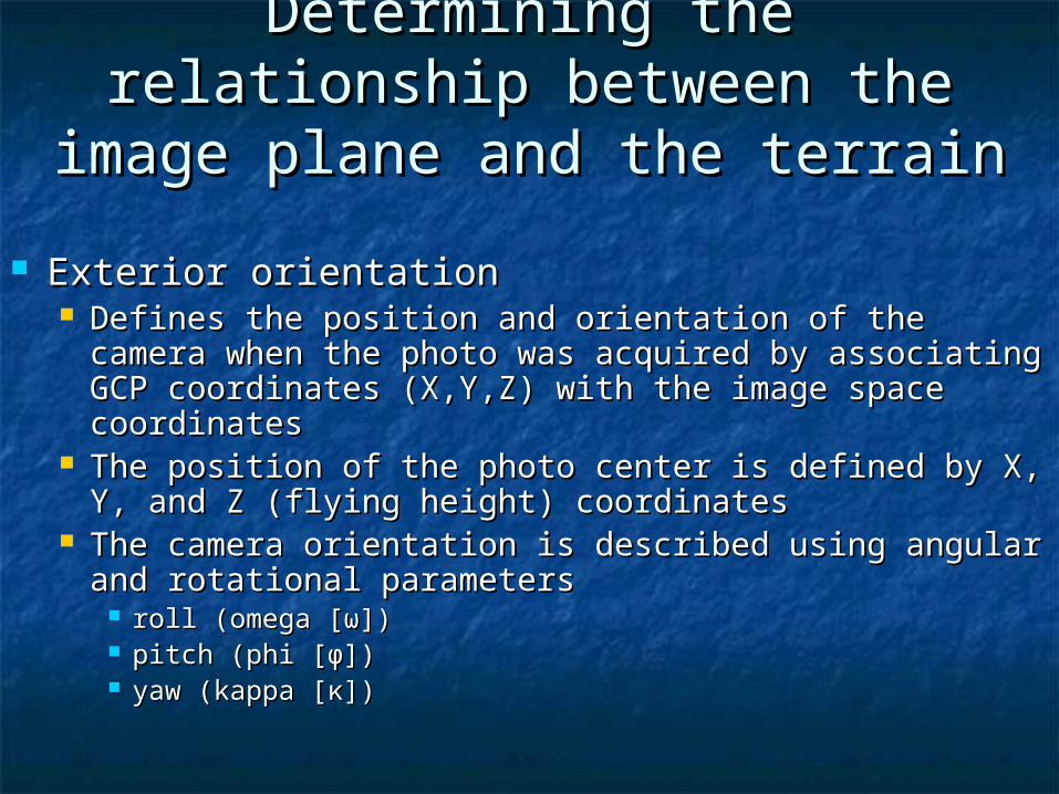
Determining the relationship Determining the relationship between the image plane and between the image plane and
the terrainthe terrain
Exterior orientationExterior orientation Defines the position and orientation of the camera Defines the position and orientation of the camera
when the photo was acquired by associating GCP when the photo was acquired by associating GCP coordinates (X,Y,Z) with the image space coordinatescoordinates (X,Y,Z) with the image space coordinates
The position of the photo center is defined by X, Y, The position of the photo center is defined by X, Y, and Z (flying height) coordinatesand Z (flying height) coordinates
The camera orientation is described using angular The camera orientation is described using angular and rotational parameters and rotational parameters
roll (omega [ω])roll (omega [ω]) pitch (phi [ϕ])pitch (phi [ϕ]) yaw (kappa [κ])yaw (kappa [κ])

What can you get out of all What can you get out of all this?this?
Create orthorectified image mosaicsCreate orthorectified image mosaics Removal of camera and relief displacement to Removal of camera and relief displacement to
create an image map (convert from central create an image map (convert from central perspective to orthogonal perspective)perspective to orthogonal perspective)
Create oriented images that can be used Create oriented images that can be used in stereo analystin stereo analyst
Derive spot elevations, contours, or digital Derive spot elevations, contours, or digital elevation modelselevation models
Measure heights of featuresMeasure heights of features Draw planimetric features to create or Draw planimetric features to create or
update mapsupdate maps