Introduction to Relational Databaseweb.pdx.edu/~gerbing/325/Resources/IntroDB.pdf · Introduction...
23
Introduction to Relational Database David Gerbing School of Business Administration Portland State University
Transcript of Introduction to Relational Databaseweb.pdx.edu/~gerbing/325/Resources/IntroDB.pdf · Introduction...
Introduction to Relational Database
David Gerbing
School of Business Administration
Portland State University
Table of Contents
SECTION I BASIC RELATIONAL DATABASE CONCEPTS ..... 1 Introduction ............................................................................................................................................................ 2
Database Management Systems ......................................................................................................................... 2 History ................................................................................................................................................................ 3
Database Structure ................................................................................................................................................ 4 Tables ................................................................................................................................................................. 4 Limitations of Representing Disparate Data Types with a Single Table ........................................................... 5 One-to-Many Relationships across Multiple Tables .......................................................................................... 7
Forms .................................................................................................................................................................... 12 Database Analysis ................................................................................................................................................ 13
Queries ............................................................................................................................................................. 14 Reports ............................................................................................................................................................. 14
Example: The Invoicing Database ..................................................................................................................... 16 Invoicing Structure ........................................................................................................................................... 16 OrderLine subform ........................................................................................................................................... 18
Database Design and Use .................................................................................................................................... 19 References ............................................................................................................................................................. 21
Further Reading ............................................................................................................................................... 21 Endnotes ........................................................................................................................................................... 21
© David W. Gerbing, 2013

Section I Basic Relational Database Concepts
This section introduces the basic vocabulary and central concepts of a relational database, including the tables that store the data and the one-to-many relationships that link the data across tables. This section also introduces the data analysis techniques of queries and reports. These concepts are applied to the description of an invoicing database.
Relational Database
2 Gerbing © 2013
Introduction
Databases store and organize data. The names, addresses, and phone numbers in a phone book constitute a database, as does a collection of recipes stored on a set of index cards.
A database is a stored, structured, integrated and retrievable set of data.
Today most organizations and businesses store their databases on computer systems. Computerized databases include accounting applications such as invoicing, accounts receivable, and accounts payable. Other business examples include sales management applications organized around lists of customers and potential customers, inventory control, and the pictures and descriptions of a company’s products available for sale over the Internet.
Database Management Systems
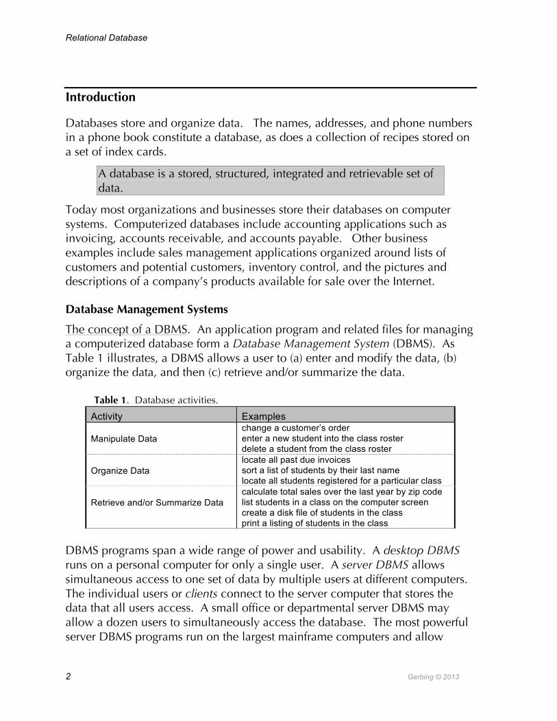
The concept of a DBMS. An application program and related files for managing a computerized database form a Database Management System (DBMS). As Table 1 illustrates, a DBMS allows a user to (a) enter and modify the data, (b) organize the data, and then (c) retrieve and/or summarize the data.
Table 1. Database activities.
DBMS programs span a wide range of power and usability. A desktop DBMS runs on a personal computer for only a single user. A server DBMS allows simultaneous access to one set of data by multiple users at different computers. The individual users or clients connect to the server computer that stores the data that all users access. A small office or departmental server DBMS may allow a dozen users to simultaneously access the database. The most powerful server DBMS programs run on the largest mainframe computers and allow
Activity Examples
Manipulate Data change a customer’s order enter a new student into the class roster delete a student from the class roster
Organize Data locate all past due invoices sort a list of students by their last name locate all students registered for a particular class
Retrieve and/or Summarize Data calculate total sales over the last year by zip code list students in a class on the computer screen create a disk file of students in the class print a listing of students in the class

I. Database Concepts
Gerbing © 2013 3
hundreds, thousands, or even tens of thousands of users, all simultaneously modifying, processing, and retrieving data.
Some specific DBMS programs. The most widely installed DBMS at the personal computer level is Microsoft Accessi, restricted to the Windows family of operating systems. The most widely used DBMS that runs on both Windows and Macintosh personal computers is Filemaker Pro. PC Magazineii (2012) named FileMaker Pro 12 as Editor’s Choice for Best Personal Database. One reason for this high rating is that Filemaker Pro is simpler to use than MS Access but still delivers much of the power of the more sophisticated and correspondingly more difficult to use DBMS. Filemaker also more easily generalizes from one to hundreds of users, whereas Access is limited to only several users at a time.
Large companies and organizations run their database systems on mainframe computers. Examples include airline reservation systems, bank records, and student records for large universities. The most widely installed large-scale DBMS is Oracleiii. The large-scale DBMS with the second highest number of installations is IBM’s DB2iv. Microsoft’s entry into the large-scale database field is SQL Serverv, which is often integrated with a graphical user-interface provided by MS Access (or similar product such as 4D). Versions of these large-scale systems also run on smaller computers.
The Unix world offers several powerful commercial and open-source (free) DBMS’s. Perhaps the most powerful and full-featured open-source database that runs on Windows and Unix (and therefore Macintosh) is PostgreSQLvi. MySQL is another popular open-source product, particularly for working with data on web sites such as customer lists and products offered for salevii. MySQL is more of a file manager than a true relational database, a kind of database-light. SQLite is a very small free, open source database that is widely used in many applications. For example, SQLite is at the core of many iPhone applications, providing the structure for storing and organizing data.
History
An IBM researcher, Ted Codd, proposed the concept of a relational database in 1970. Based on Codd’s work, IBM developed the first versions of the standard relational database programming language called SQL. IBM, however, already sold a type of commercially successful database that preceded the relational database, so the company did not innovate for fear of undermining their existing product. Larry Ellison seized the opportunity in the early 1980s and founded Oracle Corporation, which offered the first commercial relational database
Relational Database
4 Gerbing © 2013
based on the SQL language. Oracle’s database market preeminence continues todayviii,ix.
Appearing in 1985 on the Macintosh, 4D was one of the first database programs for a personal computer. 4D was also the very first database application to offer a graphical user interface – when all other mainframe and PC databases were limited to text interfaces.
Database Structure
Different DBMS’s organize data differently. The most common type of database structure is the relational database.
A relational database stores all data in a series of related tables.
Some forms of databases (hierarchical and network) predate the relational database, and a newer form of database structure, the object-oriented database, is emerging. However, the vast majority of contemporary databases, including those previously discussed such as Microsoft Access and 4D, follow the relational model.
Tables
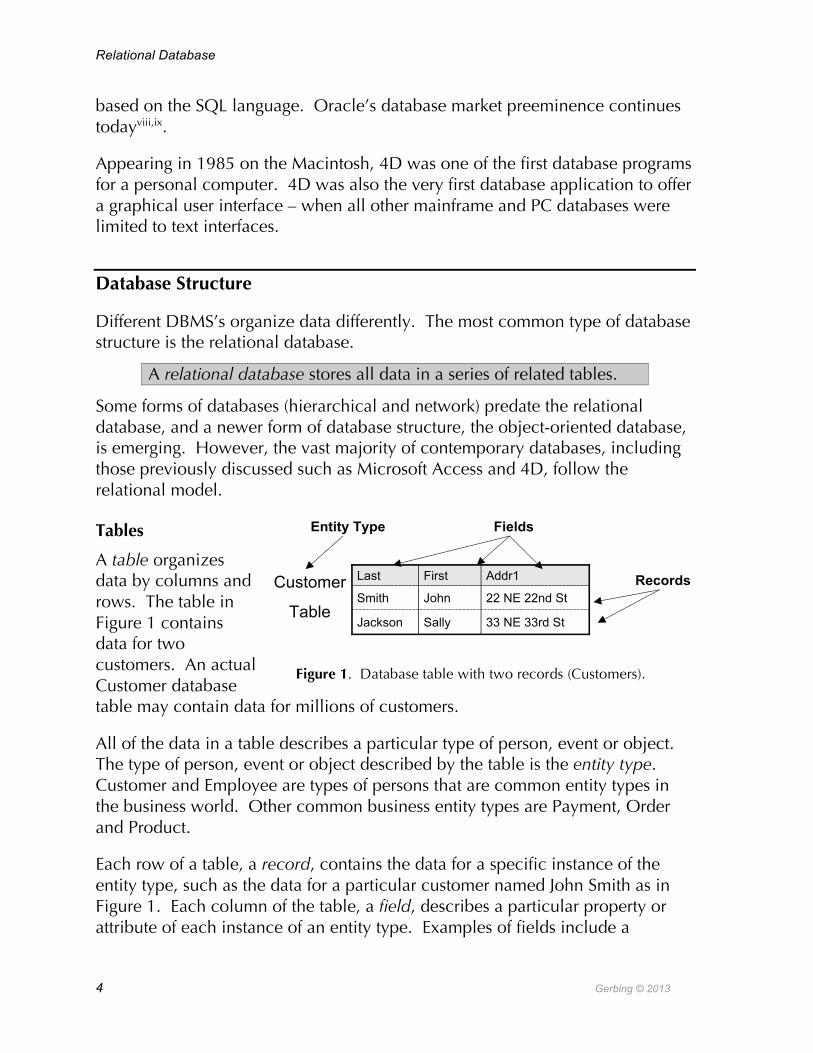
A table organizes data by columns and rows. The table in Figure 1 contains data for two customers. An actual Customer database table may contain data for millions of customers.
All of the data in a table describes a particular type of person, event or object. The type of person, event or object described by the table is the entity type. Customer and Employee are types of persons that are common entity types in the business world. Other common business entity types are Payment, Order and Product.
Each row of a table, a record, contains the data for a specific instance of the entity type, such as the data for a particular customer named John Smith as in Figure 1. Each column of the table, a field, describes a particular property or attribute of each instance of an entity type. Examples of fields include a
Figure 1. Database table with two records (Customers).
33 NE 33rd StSallyJackson
22 NE 22nd StJohnSmith
Addr1FirstLastCustomer
Table
Fields
Records
Entity Type

I. Database Concepts
Gerbing © 2013 5
customer’s last name, called Last in Figure 1. Many fields in a database store alphanumeric characters, such as a person’s last name. Other fields represent numbers such as invoice subtotal, dates such as the date of issuing an invoice, or a simple yes or no.
Ideally all data in a table describes characteristics of a single thing or event. Further, each field in the table should describe a single, specific characteristic of that thing or event.
A guiding principle of database design is that each field should describe as small amount of information as possible.
For a Customer table, instead of a single field called Name, include two fields, LastName and FirstName. If the situation requires more information about a person’s name, then include four fields: Salutation, LastName, FirstName, and MidName. Always store each distinct, small piece of information in a separate field.
Multiple pieces of information jammed together into a single field complicate the processing of the distinct pieces of information. If a name field stores name information as "John Smith", then sorting people by their last names would be difficult because each last name is embedded within a larger field. Instead of just directly locating the field for the last name and sorting, the computer would have to find the generic name field, search within the field for a space, then identify the last name as the information after the space to the end of the field, store that extracted information somewhere, and then sort on that extracted information.
A relational database could consist of only a single table, called a flat-file database, but a single table is typically far from optimal. The next section explores some of the problems that develop when a single table stores information for multiple objects or events.
Limitations of Representing Disparate Data Types with a Single Table
To illustrate the need for multiple tables, consider a veterinarian’s database that records information regarding customers and pets. In addition to storing all the usual information about a customer – name, address, and phone number, etc. – the veterinarian also records information about each of the customer’s pets. How many pets can a customer have? The answer is many; the specific number varies from customer to customer. One customer may have only a single cat, another customer may have one dog and one cat, and another customer may have four birds.

Relational Database
6 Gerbing © 2013
How can the varied information regarding the number and types of pets be recorded in a flat-file database? How can customer information and pet information all be jammed together into a single table? There are two alternatives, both undesirable.
Attempted Solution #1: Repeating groups. One attempted solution for storing customer and pet information within a single table places the pet information at the end of each customer record. Figure 2 illustrates this situation. Each pet’s name, species, and birth date for a single customer are recorded at the end of that customer’s record.
Multiple displays of the same information (Pet Type and Birthdate) for different objects (Pets) on the same record (Customer) are a repeating group. One problem with repeating groups is that different people require differing numbers of fields to describe their situation. A related problem is that the number of repeating groups limits the number of pets for a customer. Providing a large number of pets to accommodate the customer with the most pets does not preclude the possibility that a new customer may still have even more pets. At the same time, a large number of pet fields leaves most pet fields in the database empty as the majority of customers have only a single pet or two. Another problem of using repeating groups is that adding an additional set of fields to describe each pet is unwieldy and difficult to update and maintain. For example, to add the date of the last vaccination for each pet would require adding a field for each repeating group on each Customer record.
Attempted solution #2: Redundant data. A second potential solution for
9/15/99
BrthDt2
Cat
Type2
Muffy
Nm2
9/15/99
4/18/97
BrthDt1
Cat
Dog
Type1
Fluffy
Spot
Nm1
33 NE 33rd StSallyJackson
22 NE 22nd StJohnSmith
Addr1FirstLast
Repeating Group 1 Repeating Group 2
Figure 2. Problem: Forcing information from two entities, customers and pets, into a single table with repeating groups.
Figure 3. Problem: Forcing information from two entities, customers and pets, into a single table with multiple rows with redundant information.
9/15/99CatMuffy33 NE 33rd StSallyJackson
9/15/99
4/18/97
BrthDt1
Cat
Dog
Type1
Fluffy
Spot
Nm1
33 NE 33rd StSallyJackson
22 NE 22nd StJohnSmith
Addr1FirstLast
Multiple Rowsof RedundantData

I. Database Concepts
Gerbing © 2013 7
storing information for multiple pets in the Customer table creates a new record for each pet. Figure 3 illustrates the situation in which Sally Jackson owns two cats, so two Sally Jackson records appear in the Customer table. The customer information for Sally Jackson repeats for each of the two records, an example of redundant data.
One problem with redundant data is wasted space. This example shows just three fields for a customer, but there may be tens of such fields in an actual database. All of this information must be copied for every multiple record. Of greater concern is the difficulty of updating repeatedly copied information. If a customer’s address changes, all records with that address must also change. If only some of these records are modified, the same customer will have multiple addresses in the database.
One-to-Many Relationships across Multiple Tables
Normalization. The solution to the related problems of repeating groups and redundant data is data normalization. The formal definition of normalization involves several rulesx. The following idea captures much (not all) of the meaning of these rules.
Normalization avoids redundant data by placing data that describes a specific entity type only in the table for that entity type.
The design goal of normalization for constructing a relational database usually results with data placed in multiple tables. Simply put, customer data goes into the customer table and pet data goes into the pet table. In place of one table vainly attempting to blend disparate types of information, reduce the different types of information down into their basic types – customers and pets in this example – so that each type of information resides in its own table.
Key fields. A relational database typically stores many distinct types of information. Only one kind of information is stored in a table, so a database typically contains many tables.
Most relational databases consist of several or even tens of related tables.
What is needed is a way to relate entries in one table to the corresponding entries in a related table. Referring to Figures 2 and 3, Sally Jackson has two cats, so if pets are placed into their own table, then somehow the data organization need indicate which two cats Sally Jackson owns.
Relational Database
8 Gerbing © 2013
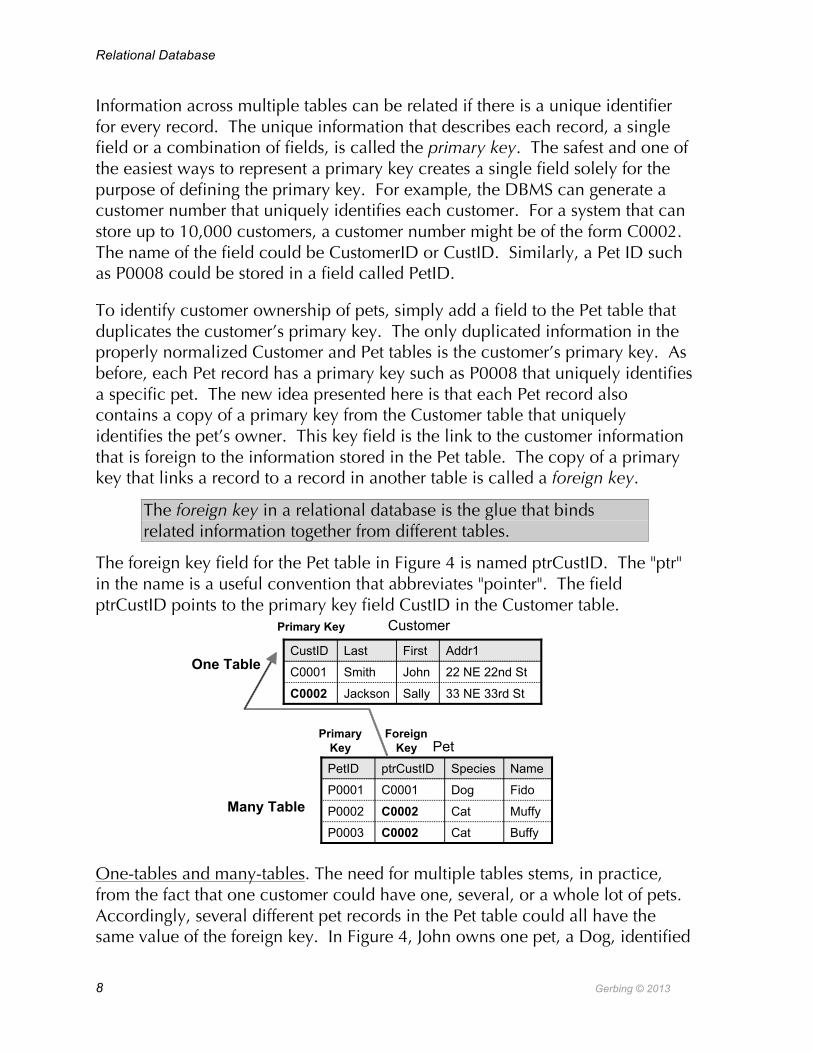
Information across multiple tables can be related if there is a unique identifier for every record. The unique information that describes each record, a single field or a combination of fields, is called the primary key. The safest and one of the easiest ways to represent a primary key creates a single field solely for the purpose of defining the primary key. For example, the DBMS can generate a customer number that uniquely identifies each customer. For a system that can store up to 10,000 customers, a customer number might be of the form C0002. The name of the field could be CustomerID or CustID. Similarly, a Pet ID such as P0008 could be stored in a field called PetID.
To identify customer ownership of pets, simply add a field to the Pet table that duplicates the customer’s primary key. The only duplicated information in the properly normalized Customer and Pet tables is the customer’s primary key. As before, each Pet record has a primary key such as P0008 that uniquely identifies a specific pet. The new idea presented here is that each Pet record also contains a copy of a primary key from the Customer table that uniquely identifies the pet’s owner. This key field is the link to the customer information that is foreign to the information stored in the Pet table. The copy of a primary key that links a record to a record in another table is called a foreign key.
The foreign key in a relational database is the glue that binds related information together from different tables.
The foreign key field for the Pet table in Figure 4 is named ptrCustID. The "ptr" in the name is a useful convention that abbreviates "pointer". The field ptrCustID points to the primary key field CustID in the Customer table.
One-tables and many-tables. The need for multiple tables stems, in practice, from the fact that one customer could have one, several, or a whole lot of pets. Accordingly, several different pet records in the Pet table could all have the same value of the foreign key. In Figure 4, John owns one pet, a Dog, identified
Customer
Pet
One Table
Many Table
Primary Key
PrimaryKey
ForeignKey
C0002
C0001
CustID
33 NE 33rd StSallyJackson
22 NE 22nd StJohnSmith
Addr1FirstLast
BuffyCatC0002P0003
P0002
P0001
PetID
MuffyCatC0002
FidoDogC0001
NameSpeciesptrCustID

I. Database Concepts
Gerbing © 2013 9
by primary key value P0001. Sally owns two cats, identified, respectively, by primary keys P0002 and P0003. Both of Sally’s cats have the same foreign key field, C0002, so both pets belong to the same customer, Sally. Although each customer can own many pets, each pet is owned by only one customer.
In this example the Customer table is called the one-table and the Pet table is called the many-table. The one-table contains the primary key field and the related many-table contains the corresponding foreign key field. One record in the one-table could potentially relate to many records in the many-table, but each record in the many-table points to exactly one record in the one-table.
To relate a one-table to a many-table, match each set of one or more identical values of the foreign key in the many-table with the corresponding single value of the primary key in the one-table.
For example, in Figure 4, the value of the foreign key C0002, occurs twice. The two corresponding Pet records relate to the single record in the Customer table with the same primary key value, Sally’s record. A one-table and the related many-table together define a one-to-many relationship.
This relationship of the type between customers and pets strikes at the heart of the relational database. The tables and defining fields, plus the one-to-many relations among the tables, define the database structure.
The ability to translate aspects of real life into the language of one-to-many relationships is a primary skill in the construction of a relational database.
The concept of a one-to-many relationship is pervasive and fundamental. Table 2 lists more examples.

Relational Database
10 Gerbing © 2013
Table 2. Examples of One-to-Many Relationships
One ___ can have Many ___ Each instance of Many points to only One
One customer owns many animals Each animal has only one owner One animal gets many vaccinations Each vaccination is given to only one animal One invoice includes many invoice lines Each invoice line appears on only one invoice One Product appears on many invoice lines
Each invoice line has only one Product
One musician produces many albums Each album is produced by only a single musician One company hires many employees Each employee works only for a single company One zip code contains many customers Each customer has only a single zip code One customer makes many orders Each order goes only to a single customer One employee invests in many IRAs Each IRA is owned by only a single employee
Entity relationship diagram. A one-to-many relationship can be illustrated with a diagram.
An entity relationship diagram (ERD) represents each table with a rectangle, each relationship with a line connecting two rectangles, and the end of line adorned with a | for 1 and a < or > for many.
For example, represent the relation One Customer can have many Pets and each Pet belongs to a single
Customer with the ERD:
Some ERD’s are drawn with the convention that the vertical bar is replaced with a 1 and the < or > is replaced with an M for many. The ERD provides convenient shorthand for sketching the entire database structure.
The one-to-many relationship pertains to the two tables only with respect to each other. In one relationship a single table may be a one-table and in another relationship the same table may be a many-table. For example, one customer may own many pets and each pet is owned by one customer, but one pet may have many vaccinations and each vaccination is given to only one pet. In this example the Pet table is a many-table with respect to customers and a one-table with respect to vaccinations.
Customers Pets
I. Database Concepts
Gerbing © 2013 11
Automatic lookup. A relational DBMS organizes the data according to the specified one-to-many relationships. A one-to-many relationship establishes an automatic lookup, which automatically links the information in the related tables throughout the operation of the database.
The user can automatically locate, select, and display values in one related table while working in the other related table.
To the person who enters and modifies data in the database, the user, information stored in multiple related tables appears on-screen as a single unit. Information in the related tables is automatically made available to the database user.
For example, the receptionist in the veterinarian’s office has a screen display for entering a customer’s name. Enter the customer’s name and a properly designed DBMS automatically displays not only all the customer’s information, but also all the relevant records from the related many-table, a list of the customer’s pets. Moving to the list of pets on the screen display, the receptionist can click a button that indicates the desire to enter the information for a new pet. Behind the scenes, the DBMS first creates a new record in the related many-table, the Pet table, and then automatically creates a value for the Pet primary key and copies the Customer primary key field into the Pet foreign key field. Spared any needed knowledge of these technical details, the receptionist sees a new, blank line on the screen with spaces for entering the needed information such as the pet’s name, species, and birthdate.
Referential integrity. The DBMS also maintains a set of rules, some integrity constraints called referential integrity, to foster the validity of the primary and foreign keys. The three basic rules of referential integrity follow.
1. For a many-table, each value of the foreign key must match a primary key value in the corresponding one-table. Ex. The Customer ID for Fido in the pet table matches John’s Customer ID in the customer table.
2. If a primary key field is changed, then all foreign key fields in all related many-tables should change accordingly. Ex. If John’s Customer ID changes, then the corresponding values of this ID for all of John’s pets in the pet table must also change.
3. If related many records exist then the corresponding record in the one-table cannot be deleted first. Ex. If John has some pets, John’s customer information cannot be deleted first.
Usually these rules can be invoked so that the DBMS automatically applies these rules in the background. For example, when a Customer’s ID is changed,
Relational Database
12 Gerbing © 2013
the usually automatic application of referential integrity changes all related values of the corresponding foreign keys.
Given a database structure, data can be entered. Next we examine the means to enter and display the data on-screen in a database.
Forms
Tables store the data. Forms provide the format for displaying the data from one or more tables. A form may format the display of data on-screen for display only or also for entering and modifying data. A form may also format the display of data on the printed page.
Each form is attached to a specific table. A single table, however, may have a dozen or more forms. Each form provides a specific view of all or some of the data for a single record or a list records in the table. A form can also display data for related tables as well.
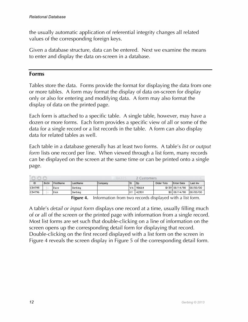
Each table in a database generally has at least two forms. A table’s list or output form lists one record per line. When viewed through a list form, many records can be displayed on the screen at the same time or can be printed onto a single page.
Figure 4. Information from two records displayed with a list form.
A table’s detail or input form displays one record at a time, usually filling much of or all of the screen or the printed page with information from a single record. Most list forms are set such that double-clicking on a line of information on the screen opens up the corresponding detail form for displaying that record. Double-clicking on the first record displayed with a list form on the screen in Figure 4 reveals the screen display in Figure 5 of the corresponding detail form.
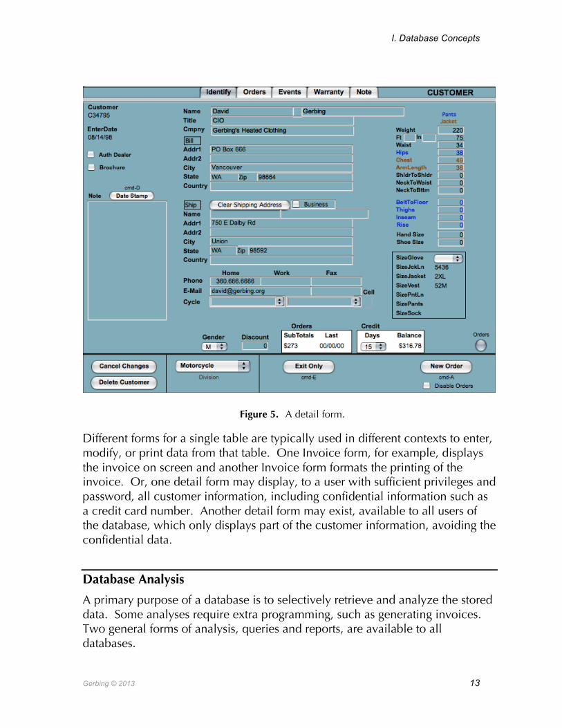
I. Database Concepts
Gerbing © 2013 13
Figure 5. A detail form.
Different forms for a single table are typically used in different contexts to enter, modify, or print data from that table. One Invoice form, for example, displays the invoice on screen and another Invoice form formats the printing of the invoice. Or, one detail form may display, to a user with sufficient privileges and password, all customer information, including confidential information such as a credit card number. Another detail form may exist, available to all users of the database, which only displays part of the customer information, avoiding the confidential data.
Database Analysis
A primary purpose of a database is to selectively retrieve and analyze the stored data. Some analyses require extra programming, such as generating invoices. Two general forms of analysis, queries and reports, are available to all databases.

Relational Database
14 Gerbing © 2013
Queries Searching and sorting information is a fundamental purpose of a database. Which customers live in the 97201 zip code? Which orders were entered on 2/21, listed by size of the order? How many widgets were sold during the last month? Which accounts are overdue, listed by the amount overdue? A database query answers these kinds of questions.
A database query retrieves records from the database according to specified criteria.
For example, the records displayed by the list form in Figure 4 (p. 12) display the results of a query for customers with the last name of Gerbing. Indeed, obtaining the type of information provided by a database query is one of the primary purposes for maintaining a database.
An index specifies the exact location of where the information is located on the hard disk. Indexing a field greatly speeds up searching for information in a specific field, such as a LastName of Rumbinsky. For example, if LastName is an indexed field, an ordinary PC can search through tens of thousands of Customer records and retrieve all customers with a last name of Rumbinsky in less than second. If the field is not indexed, this query could take much longer.
Without the index the DBMS would provide a more inefficient sequential search. A sequential search begins with the first customer record, then looks at the next customer record, and so on, until a record with the LastName of Rumbinsky is located. If the LastName filed is indexed, then, just like a person looking up the page number of a concept in an index of a book, the DBMS can directly identify the physical location of the disk that contains the Rumbinsky customer information.
Indexing greatly speeds up a query, such as querying on a value of LastName, so why not index all database fields? The answer is that indexing is not without cost. The index must be created and perpetually updated as the database is modified. In addition, the index requires space for storing the location of all the indexed records. In practice, only those fields searched on a regular basis are indexed. Indexed fields include all primary and foreign key fields, and other relevant fields such as LastName and Zip. Fields such as FirstName, or street Address are rarely indexed.
Reports A primary reason for storing data in a database is for subsequent processing and analysis. Sometimes this information can be directly obtained, such as running

I. Database Concepts
Gerbing © 2013 15
a query that identifies and lists all Customers named Smith. The report capability of a database takes this display one step further, offering further analysis beyond that provided by a query.
The database report is a readable, formatted display of data and analysis optimized for printing.
The report editor of a DBMS allows for the page numbering, headers and footers, sorting, calculations, and other features that facilitate the printed display of information.
The query selects the database records of interest. The report specifies the analysis to perform on the selected data as well as the format for printing the results. From a selection of all employees, a report could list all the company’s departments, and then list each employee and his or her salary within each department. At the bottom of the listing for each department, the report could list the average salary and the total salary of each department. The end of the report could display the average and total salaries for the entire company.
The accompanying report analyzes invoices. This report lists all invoices by zip code for three zip codes: 18911, 18913, and 18914. The zip codes are sorted in ascending order. Customers are sorted by last name within each zip code.
The report “breaks” at the listing of each new zip code. A break area on a report separates levels of different groups, and displays calculations such as totals and averages. The report displays the sum of all the subtotals for all of the invoices within each zip code. One break area corresponds to the first sorted field, a second break area corresponds to the second sorted field, and so on.
The number of break areas specifies the number of levels. The Grand total is at the top level, the break area at the end of the report. The Grand total displays calculations based on all of the data in the report. The remaining break areas are set according to the specified sort order. The next break area, one level down after the Grand total break area, corresponds to the Zip field.
Further, the report calculates the sum of all the invoice subtotals for each zip code as well as the grand subtotal, the total sum of all subtotals for all invoices processed in the report. The total subtotal for zip code 18911 is $211, for zip code 18913 the total subtotal
Relational Database
16 Gerbing © 2013
is $258, and the largest subtotal of $1465 is for zip code 18914. The sum of all the subtotals calculated for all of the invoices in the report is $1934. All numeric values were rounded to the nearest dollar for this report.
Example: The Invoicing Database
A business sells its products – things, information, or services – to its customers. The order is taken with an on-screen order form and then the customer is billed with a printed invoice. Both the on-screen order form and the corresponding invoice consist of customer information, an invoice number and date, an order line for each product ordered, including quantity and price, and the total amount owed, including taxes and shipping. A DBMS generates and prints invoices.
Invoicing Structure
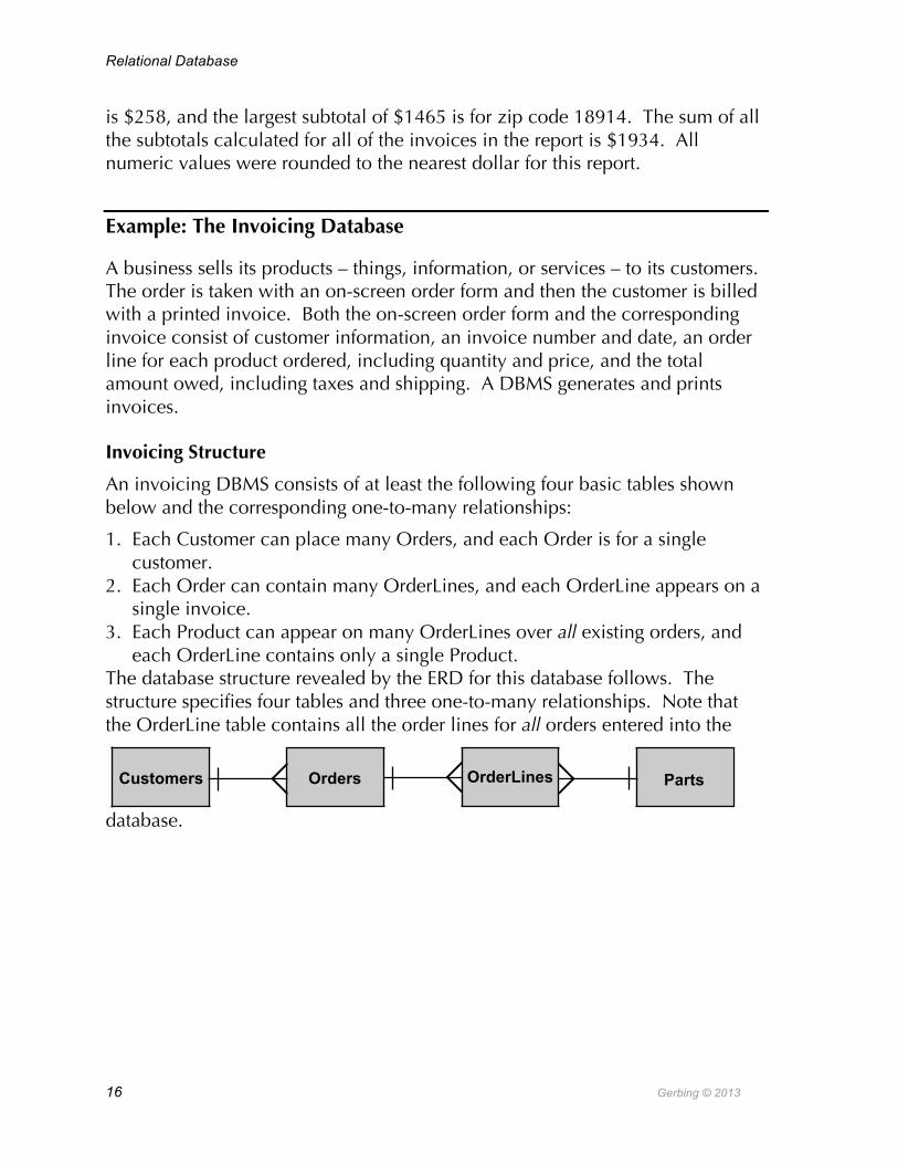
An invoicing DBMS consists of at least the following four basic tables shown below and the corresponding one-to-many relationships:
1. Each Customer can place many Orders, and each Order is for a single customer.
2. Each Order can contain many OrderLines, and each OrderLine appears on a single invoice.
3. Each Product can appear on many OrderLines over all existing orders, and each OrderLine contains only a single Product.
The database structure revealed by the ERD for this database follows. The structure specifies four tables and three one-to-many relationships. Note that the OrderLine table contains all the order lines for all orders entered into the
database.
Customers Orders OrderLines Parts

I. Database Concepts
Gerbing © 2013 17
Data from related one and many-tables can simultaneously appear on the same form, on-screen or printed. For example, information about an Invoice (one-table) and the related lines of information for each product ordered (related many-table) could be viewed on the same form. The information from a one-table on the form defines a detail form called the main form. The corresponding information from the related many-table defines a list form called the subform.
A relational database system represents an invoice as a main form that contains an OrderLine subform.
An invoice is not stored in the database, but is instead a form constructed from the data stored in at least four different database tables.
There is no entity called an invoice that is stored as an invoice in the database. The DBMS constructs each invoice from the information in these different tables. The invoice per se exists only as a screen display or a print out.
The main form of the invoice is based on the Order table. This form consists of information from the Order table, the date and invoice number (OrderID), as well as information from the corresponding Customer table, such as name and

Relational Database
18 Gerbing © 2013
address. The lines of information, one line for each product ordered, define the subform on the invoice. Each line of the subform is an OrderLine, which includes information from the Products table.
The retrieval of information in related tables is a key operating feature of a relational database. Given a record in a many-table, the DBMS can search for and retrieve the related information in the corresponding one-table.
When using an on-screen form, entering information into a foreign key field in the many-table results in the automatic lookup of the related data in the corresponding one-table.
For example, entering a Customer ID into the ptrCustID foreign key field on the Order form automatically retrieves and then displays the related customer information. Entering C34795 in the ptrCustID field on the on-screen form leads to the display of the related customer’s name and address, as shown in the accompanying figure.
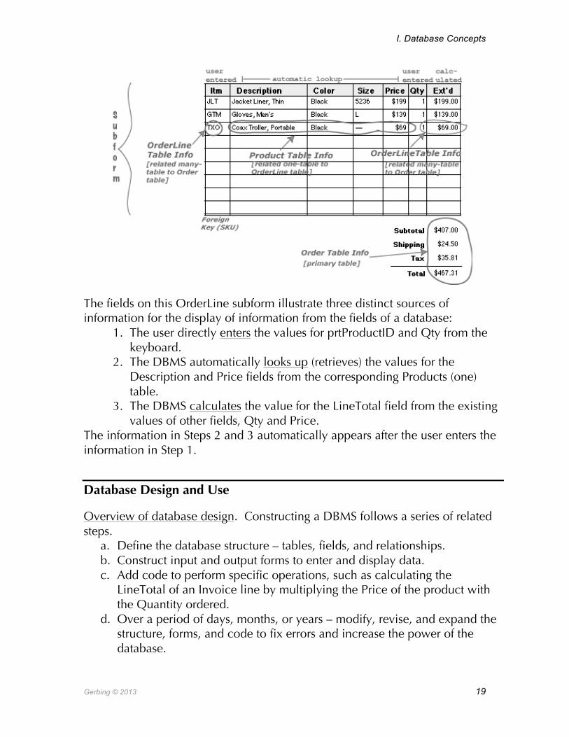
OrderLine subform
A second example of automatic lookup in an invoicing database occurs when entering information into the OrderLine table. The OrderLine displayed on the Invoice contains the ProductID, the Description, Price, Quantity, and Total for that line. However, not all of the information displayed on an order line is from the OrderLine table. The Product table stores Description and Price, as illustrated in the following figure. After Product ID is entered into the ptrProductID field on an OrderLine, the DBMS automatically finds and displays the Product’s Description and Price.
I. Database Concepts
Gerbing © 2013 19
The fields on this OrderLine subform illustrate three distinct sources of information for the display of information from the fields of a database:
1. The user directly enters the values for prtProductID and Qty from the keyboard.
2. The DBMS automatically looks up (retrieves) the values for the Description and Price fields from the corresponding Products (one) table.
3. The DBMS calculates the value for the LineTotal field from the existing values of other fields, Qty and Price.
The information in Steps 2 and 3 automatically appears after the user enters the information in Step 1.
Database Design and Use
Overview of database design. Constructing a DBMS follows a series of related steps.
a. Define the database structure – tables, fields, and relationships. b. Construct input and output forms to enter and display data. c. Add code to perform specific operations, such as calculating the
LineTotal of an Invoice line by multiplying the Price of the product with the Quantity ordered.
d. Over a period of days, months, or years – modify, revise, and expand the structure, forms, and code to fix errors and increase the power of the database.
Relational Database
20 Gerbing © 2013
Follow these steps to develop virtually any database.
Designers vs. users. After the initial implementation in Steps a-c above, the revisions in Step d require switching back and forth between designing and using the database.
The designers design the database structure and the users process the data entered and stored according to that structure.
Every DBMS provides both a means for designing the database structure – the tables, forms, and code – and a means for actually using the database in terms of entering, processing and retrieving data.
Database objects. The primary database objects and activities include Tables, Forms, Queries and Reports. Tables and forms provide the means for the database user to enter and modify data. Queries and reports are essential database user activities for gathering and analyzing information. Object Context Action on Object Example
Tables Data Data Definition: Structure and store data. Store data in a Customer table. Forms Data Data Entry and Display: The window for
entering data into the database and for displaying data.
Enter new customer data into the database or change existing data for existing customers.
Queries Analysis Locate specific records that meet a criterion.
Find all customers with a specific zip code.
Reports Analysis Generate written reports that summarize relevant information.
Print a report that lists the names and addresses of all customers grouped by zip code.
A general note about working within any programming environment.
Close windows instead of minimizing. When developing an application such a database, many different windows must be opened at various times. When finished working with a window, it is generally safer to close rather than minimize the window.
Caution → Minimizing a window leaves the window open, which may conflict with the information stored in other windows.
Closing each window when finished modifying the contents of that window prevents these unwelcome interactions.

IV. Addendums
Gerbing © 2013 21
References
Further Reading Relational Database Design Clearly Explained by Jan L. Harrington (2nd ed) Holt Rinehart & Winston (1997); ISBN: 0030315883 Database Design for Mere Mortals: A Hands-On Guide to Relational Database Design by Michael J. Hernandez Addison-Wesley Pub Co (1997); ISBN: 0201694719 Data Modeling Essentials: Analysis, Design, and Innovation by Graeme C. Simsion The Coriolis Group (1996); ISBN: 1850328773 Database Modeling & Design: The Fundamental Principles by Toby J. Teorey
Morgan Kaufmann Publishers (1994); ISBN: 1558602941
Endnotes i www.microsoft.com/office/access ii http://www.pcmag.com/article2/0,1759,1818968,00.asp iii www.oracle.com iv www.ibm.com/db2 v www.microsoft.com/sql vi www.postgresql.org vii www.mysql.org viii wwwinfo.cern.ch/db/aboutdbs/history ix www.nap.edu/readingroom/books/far/ch6.html x www.devshed.com/Server_Side/MySQL/Normal