Introduction to regulatory Framework for Damage Stability
70
Introduction to regulatory Framework for Damage Stability Dr Evangelos Boulougouris
Transcript of Introduction to regulatory Framework for Damage Stability

Introduction to regulatory
Framework for Damage Stability
Dr Evangelos Boulougouris


Overview
• In January 2009, the new harmonised probabilistic rules for damage stability became mandatory, initiating a new era of rule-making in the maritime industry.
• This constitutes the culmination of more than 50 years of work, one of the longest gestation periods of any other safety regulation.
!✓ A step change in the way safety is being addressed and
regulated, ''taking our time" is well justified. ✓ The change from introducing the new probabilistic rules for
damage stability is so fundamental that design implications are just beginning to register, driving home the realisation that "things" are no longer the way they used to be.

Titanic (1912) – 2½ hours
Sinking after collision with an iceberg

Andrea Doria (1956) – 11 hours
Capsized after collision with ’Stockholm’
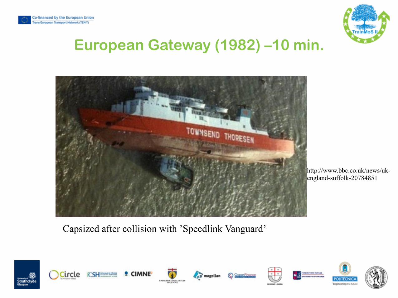
European Gateway (1982) –10 min.
Capsized after collision with ’Speedlink Vanguard’
http://www.bbc.co.uk/news/uk-england-suffolk-20784851

Herald of Free Enterprise (1987)–90s

MS Estonia ( September 1994)- less than 15min after flooding of RoRo deck

MS Express Samina (September 2000)- about 20-25 min after colliding with a reef

Sea Diamond, Apr 2007

Costa Concordia, 13 Jan 2012

Background
• Ships may suffer a damage during their service • Hull damages can be caused by collision, grounding
or enemy action in case of warships • The outcome such a damage would be change of
draught, trim and heel • If the vessel doesn’t have sufficient reserved
buoyancy and stability, a damage may result to the loss of the ship
• In order a ship to survive the vessel has to be subdivided into a number of watertight compartments
• Flooding of a cer tain number of adjacent compartments should not lead to slow sinking, progressive flooding or rapid capsize of the ship

Backgroundhttps://www.youtube.com/watch?v=XZP9fFyitn4• Watertight subdivision has a history of
more than 1,000 years • Chinese junks (ocean going ships) were
using it since 12th century • Isambard Kingdom Brunel’s Great Eastern
built in 1858 had not only watertight subdivision but it was also double hull
• At the end of 19th century in Great Britain the Parliament chartered a “Bulkhead Committee” to investigate the impact of TBhds
• The first Merchant Shipping Act of 1854 is the f irst known legal requirement addressing safety at sea concerning watertight bulkheads
• I n 1 8 9 1 t h e c o m m i t t e e proposed the installation of TBhds in order to make ships l o n g e r t h a n 4 2 5 f t 2 -compartment.
• As a motive for the industry, such ships would be able to carry less life boats

Background• The tragic loss of the Titanic in April
1912 stressed the need for international r e g u l a t i o n s f o r t h e w a t e r t i g h t subdivision of the hull
• 1st SOLAS 20/1/1914 • Should have been applied Jul 1915 • Stopped by WWI • Next SOLAS Conference 1929 (1933) • Technical developments led to SOLAS
1948
!!
• T h e n e x t s t e p w a s SOLAS 1960
• Finally, the 1974 SOLAS Convention was held in London
"RMS Titanic 3" by F.G.O. Stuart (1843-1923) – http://www.uwants.com/viewthread.php?tid=3817223&extra=page%3D1. Licensed under Public Domain via Commons

Definitions
1. Floatability: the ability of the vessel to support a given weight W, by means of the hydrostatic pressure acting on the underwater surfaces, giving rise to the buoyancy force, B.
Furthermore, to achieve a condition of upright equilibrium, the weight and force vectors have to act along the same vertical line on the centre plane of the vessel.
Definitions
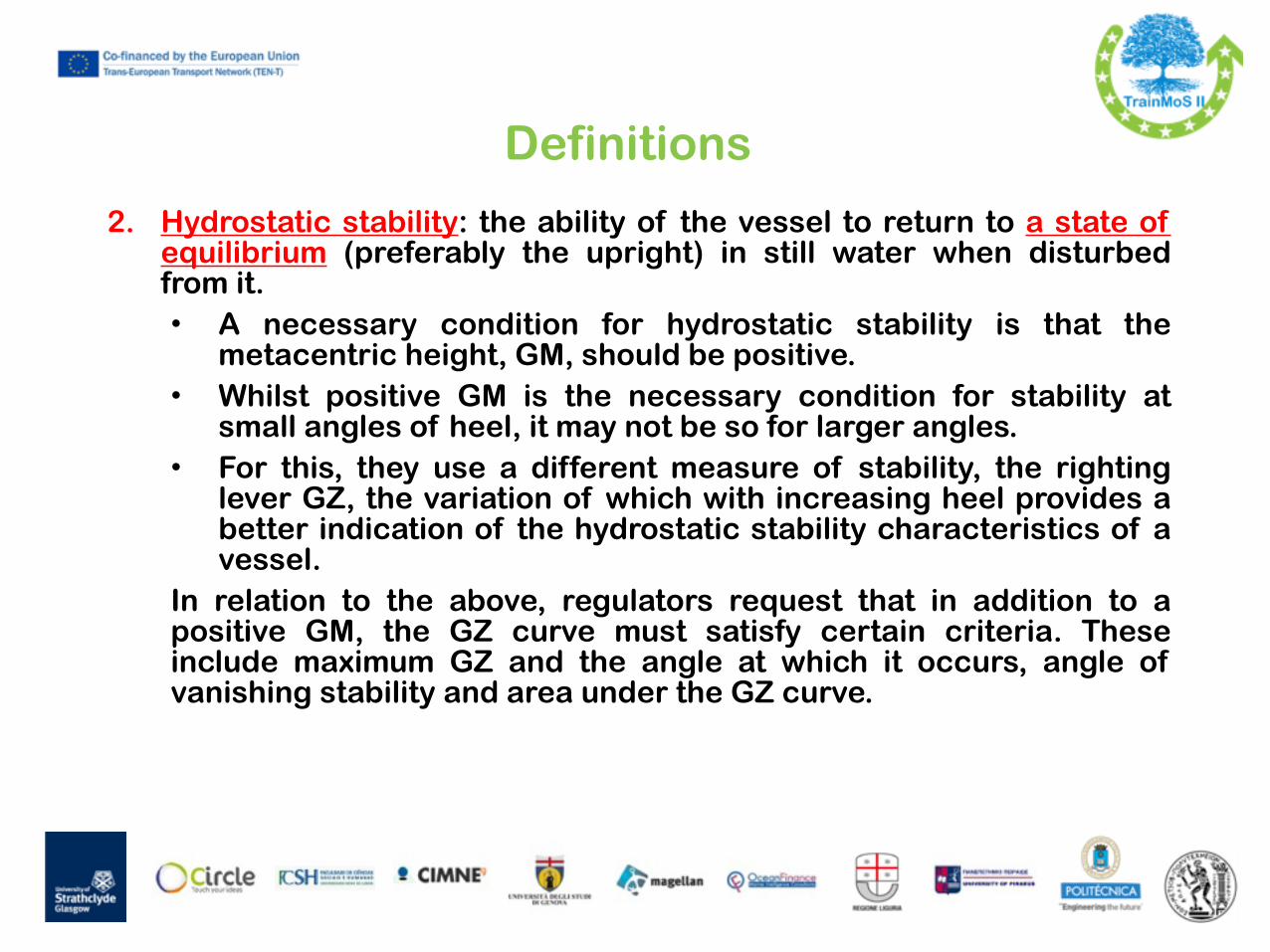
2. Hydrostatic stability: the ability of the vessel to return to a state of equilibrium (preferably the upright) in still water when disturbed from it. • A necessary condition for hydrostatic stability is that the
metacentric height, GM, should be positive. • Whilst positive GM is the necessary condition for stability at
small angles of heel, it may not be so for larger angles. • For this, they use a different measure of stability, the righting
lever GZ, the variation of which with increasing heel provides a better indication of the hydrostatic stability characteristics of a vessel.
In relation to the above, regulators request that in addition to a positive GM, the GZ curve must satisfy certain criteria. These include maximum GZ and the angle at which it occurs, angle of vanishing stability and area under the GZ curve.

GZ curve
• If a vessel is damaged so that part of her internal volume is flooded, she will sink, heel and trim until she reaches a condition in which reserve buoyancy (i.e. buoyancy above the initial waterline) has been brought into effect to offset the lost buoyancy until equilibrium is again restored, but with the vessel possibly taking a steady angle of heel.
• For the most onerous cases GM is likely to decrease and the GZ curve characteristics are likely to diminish in all regards.
• Capsize of the vessel occurs if GM became negative with the vessel upright and there were no positive righting levers in the residual GZ curve (GZ curve after damage).
• On the basis of this reasoning, damage stability can be enhanced by ensuring that the residual GZ curve satisfied certain criteria.
• The stability of ships is, in general, related to both intact and damage stability requirements.
• For passenger vessels this is normally assessed by their stability in a damaged condition, i,e. by their residual stability.

GZ Cross Curves of Stability
Source: Ship stability for masters and mates

Evolution of damage stability standards for passenger ships in SOLAS
Fran
cesc
utto
& P
apan
ikol
aou,
Buo
yanc
y, st
abili
ty, a
nd su
bdiv
isio
n: fr
om A
rchi
med
es to
SO
LAS
200
9 an
d th
e w
ay a
head
, Pro
c. IM
echE
Vol
. 225
Par
t M: J
. Eng
inee
ring
for t
he M
ariti
me
Envi
ronm
ent
Definitions
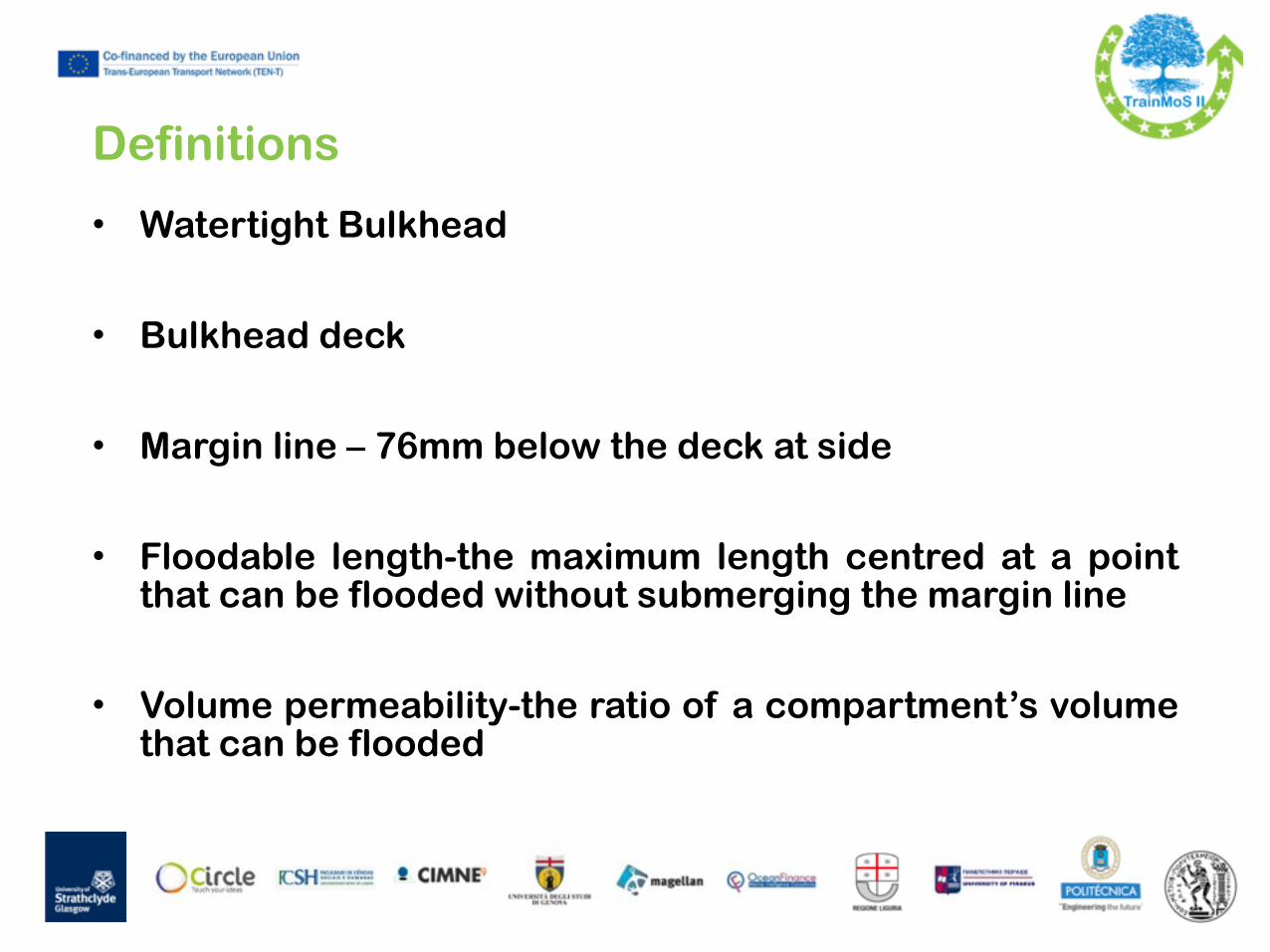
• Watertight Bulkhead
!• Bulkhead deck
!• Margin line – 76mm below the deck at side
!• Floodable length-the maximum length centred at a point
that can be flooded without submerging the margin line
!• Volume permeability-the ratio of a compartment’s volume
that can be flooded

Damaged Stability
Watertight subdivision• A ship might sink due to:
• Carrying a weight larger than her displacement
• Flooding due to: • Grounding • Collision • Enemy action • Operation of a system open to the sea
• For the case water finds its way in, the designer has to make sure that: • The loss of transverse stability is minimum
• The damage to the cargo is minimum • The vessel has sufficient longitudinal stability
• The loss of residual buoyancy is minimum
• Ideally, the ship should sustain more and more flooding without loss of stability until it sinks bodily by loss of its reserve of buoyancy (foundering).
• In order to achieve that, the ship is subdiv ided to a number of watertight compartments
16/11/2015 21
76

Damaged Stability
Watertight subdivision
• The bulkheads must be watertight up to the bulkhead deck and able to withstand the water pressures they might be subject to after damage
• Ships over certain length should have a watertight inner bottom (double bottom) extending from the fwd col l is ion bhd up to the afterpeak bhd
• Tankers, large warships and many Ropax have in addition longitudinal side bulkheads in order to minimize the transverse extent of flooding
16/11/2015 22

Damaged Stability
Damaged condition
• To assess the ability of the ship to withstand the damage a number of different damage scenarios should be checked at design stage
• For every damage condition, the naval architect is checking:
• The damaged waterline, heel and trim
• The damaged stability according to standards laid down in the Rules
16/11/2015 23

Damage Stability Calculations
• When a ship is damaged, creating a hole in the hull, water enters the ship. This results in: • Increase in draft • Change in trim • Change in heel !
• The result of this flooding can be determined two ways: !
• Lost Buoyancy Method • Added Weight Method
!• “Lost Buoyancy” approach is followed in all regulations

Damaged Stability 25
Example based on idea presented in Handbuch derWerften and later used by Watson Starting point: Intact condition
Indices denote different conditions: 0 intact hull with original draft T0
T0
Associated with initial displacement volume: V0 !Associated with initial intact stability: GM0 = KB0 + BM0 – KG0
16/11/2015

Damaged Stability 26
Approach: “Lost Buoyancy”
After hull damage: ship loses displacement volume draft increases because of buoyancy lost !
T0
loss of available volume κ v0
16/11/2015

Damaged Stability 27
Permeability μ considered
Flooded compartment does not fill completely with water. !Compartments contain: - equipment - furniture - structural components - cargo
Permeability = ———————Available Volume Total Volume
Similarly we have the area permeability: µf = water area at waterline/total compartment area at waterline
16/11/2015

Damaged Stability 28
Homogeneous permeability assumed
Empty room µ = µv = 100%
Reality µ = µv = 95%
Model µ = µv = 95%
Watertight compartment (warship) 97% Watertight compartment (merchant) 95% Accommodation spaces 95% Machinery spaces 85% Dry cargo spaces 70% Bunkers, stores, cargo holds 60%
Typical values:
16/11/2015

Damaged Stability 29
Final damaged condition
Indices denote different conditions: 0 intact hull with original draft T0
R residual hull at final draft T=TR (incl. trim)
T0T=TR
16/11/2015

Damaged Stability 30
Notation: Artificial intact-damaged conditionIndices denote different conditions: 0 intact hull with original draft T0
R residual hull at final draft T=TR (incl. trim)
T intact hull at final draft T= TR (incl. trim)
T0T=TR
Only used for mathematical derivations
No physical meaning
16/11/2015

Damaged Stability 31
Masses remain fixed
Assumption: • cargo (or other objects) does not exit • cargo (or other objects) do not float inside room !Then: • total mass of ship constant • mass distribution (KG) constant !! VR = V0 and KGR = KG0
16/11/2015

Damaged Stability 32
Example: Pontoon with μ = 100%
1. Central compartment damaged
T0
Ll
2. Loss of buoyancy
3. Loss of volume compensated by increased draft
TR
16/11/2015

Damaged Stability 33
Intact stability
T0=3m
L=100ml =40m
Intact stability: V0 = L ⋅ B ⋅ T0 = 100 ⋅ 20 ⋅ 3 = 6000 m3
KB0 = T0 /2 = 3/2 = 1.50 m
BM0 = — = ———— = ——— = —— = 11.11 m
GM0 = KB0 + BM0 - KG0 = 1.50 +11.11 – 8.00 = 4.61 m
I0 V0
L ⋅B3/12 L ⋅ B ⋅ T0
B2 12⋅T0
202 12⋅3
KG0=8m
B=20m
16/11/2015

Damaged Stability 34
Floating position in damaged condition
L=100ml =40m
Mass constant → Volume constant
VR = (L-l) ⋅ B ⋅ TR TR = ———— = —————— = 5.00 m VR = V0
TR
6000 (100 - 40) ⋅ 20
V0 (L-l) ⋅ B
16/11/2015

Damaged Stability 35
Damage stability
L=100ml =40m
KG0=8m
TR=5 m
Damage stability: KBR = TR /2 = 5/2 = 2.50 m
BMR = — = ———— = —————— = 6.67 m
GMR = KBR + BMR - KG0 = 2.50 + 6.67 – 8.00 = 1.17 m
IR V0
(L-l) ⋅B3 12 ⋅V0
(100-40) ⋅ 203 12⋅6000
16/11/2015

Damaged Stability 36
Intact vs. Damage Intact Damaged ! KB 1.50 m 2.50 m
BM 11.11 m 6.67 m
GM 4.61 m 1.17 m
The pontoon is still stable, but has lost ΔGM = 3.44 m
Now consider an intermediate condition during flooding
16/11/2015

Damaged Stability 37
Intermediate condition
L=100ml =40m
TR
• BMR now must consider correction for free surface • on the other hand, waterline still intact Net effect: BMR as in damaged condition: BMR = 6.67 m !V0 = VR = L⋅B⋅TR- l⋅B⋅h
→ TR = ————— = ——————— = 3.60 m
h=1.50m
V0 + l ⋅B⋅h L ⋅ B
6000 + 40⋅20⋅15 100 ⋅20
16/11/2015

Damaged Stability 38
KB computed for residual underwater body
L=100ml =40m
TR
h=1.50m
V z V‧zL T
- -l‧B‧h h/2
= KB
L‧B‧TR2/2
-l‧B‧h2/2
L‧B‧TR -l‧B‧h L‧B‧TR2/2 -l‧B‧h2/2
16/11/2015
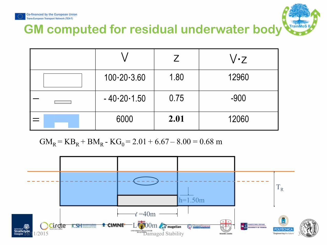
Damaged Stability 39
GM computed for residual underwater body
L=100ml =40m
TR
h=1.50m
V z V‧z100‧20‧3.60 1.80 12960
- - 40‧20‧1.50 0.75 -900
= 6000 2.01 12060
GMR = KBR + BMR - KG0 = 2.01 + 6.67 – 8.00 = 0.68 m
16/11/2015

Damaged Stability 40
Intact vs. Damage vs. Intermediate
Intact Damaged Intermediate ! KB 1.50 m 2.50 m 2.01 m
BM 11.11 m 6.67 m 6.67 m
GM 4.61 m 1.17 m 0.68 m
Pontoon still stable, but GM considerably lower than in final condition
Intermediate conditions most critical, but…
…most regulations required stability proof only for final condition
16/11/2015

Damaged Stability 41
Non-symmetric damage of waterline• change of draft • change of trim • change of heel
x0
y0
ST
ST center of intact waterline at draft T FT area of intact waterline fT damaged waterline area at draft T
sl
al
16/11/2015

Damaged Stability 42
Center of waterline shifts
• center of residual waterline no longer on symmetry plane
x0
y0
ST
SR center of residual waterline at draft T
SR
y
x
aR
sR
16/11/2015

Damaged Stability 43
Axes for moments of inertia change• main axis of inertia (= axis with minimum moment of inertia) no longer on symmetry plane
y
xx’
y’
16/11/2015
Damaged Stability
“Floodable length” is simplified concept• Useful for early estimate of damage stability (guiding arrangement of bulkheads )
+ easy to handle + no computer needed – assume constant permeability over cross section (often not true) – only approximation !!
• (Pre)historic approach • Manual procedure described in PNA • Diagrams still popular for communication
16/11/2015 44

Damaged Stability 45
“Floodable length” definitionConsider a point situated at x (from the aftmost point of ship) !“Floodable length” (at x) = ! Maximum length of the compartment having its center at x that will not submerge the margin line if symmetrically flooded. !‘Margin line’ = (often) 76 mm (3 inches) below deck at side
16/11/2015

Damaged Stability 46
Results usually displayed in diagramsx-axis: position of center of room y-axis: length of room (damage)
Possible space of solutions is triangle
FL computed exactly for several points Spline interpolation
Permeability as parameter
FL = floodable length16/11/2015

Damaged Stability 47
Floodable length curves help placing bulkheads• Isosceles triangle below curve = ship survives if room flooded • discontinuous limit curve due different permeabilities • shift bulkheads until all rooms (individually can be flooded) • two adjacent rooms can be considered by combining room lengths
two compartments combined
bulkhead
16/11/2015

Damaged Stability 48
Damage stability today analyzed by computer programs
Naval Architect specifies: • hull geometry • mass distribution (KG) • compartments
!Computer determines
• floating position • residual GM and freeboard
for all individual compartments and groups of compartments !Often applicable criteria included in code: automatic check
Source: NAPA16/11/2015
Deterministic vs. Probabilistic!
• Deterministic: • Standard dimensions of damage extending anywhere
along the ship’s length or between TBhds depending on the relevant requirements.
• A number of standard damages involving single or multiple compartments is examined
• Each damage case is to be considered for each loading condition, and the applicable criteria are to be comply with.

Deterministic vs. Probabilistic!
• Probabilistic: • The probability of survival after damage is the measure of ship
safety in damage condition, refered to as the attained subdivision index A.
• The philosophy behind the probabilistic concept is that two different ships with the same attained index are of equal safety and, therefore, there is no need for special treatment of specific parts of the ship, even if they are able to survive different damages.
• The only areas which are given special attention in the Regulations are the forward and bottom regions, which are dealt with by special subdivision rules provided for cases of ramming and grounding.
New design paradigm (from prescriptive to goal-setting design)
!• The probabilistic concept of ship subdivision affords
new degrees of freedom in ship subdivision and layout but, in this process, designers are finding it rather difficult to move away from the prescription mind-set.
• Adapting design practice to the new freedom, offered by the new rules, requires new skills, which cannot be based on experience alone.
• The need to facilitate improved understanding of what this concept entails and of its limitations and range of applicability is now paramount.

New Naval Architecture (from hull focus to total ship focus)
• With the advent of the new probabilistic rules comes a major shift in the way the fabric of Naval Architecture, namely floatability and stability is being interpreted and used.
• The margin line disappears and Naval Architecture begins to delve into superstructure, seeking to identify and distribute watertight spaces so that floatability and stability are ensured in all the extreme damage scenarios covered by the probabilistic rules.
• Consideration of upper decks for stability needs, would lead to accounting all openings, escape routes, void spaces and layout; hence intruding into ship’s operation.
• Safety, performance and functionality must now be considered concurrently through routine utilisation of optimisation techniques in early design stages.

New rules of the game (mixing probabilistic and deterministic rules)
• Introducing the new probabilistic rules for damage stability during a period when existing deterministic instruments were still being enforced, namely SOLAS '90 (globally) and Stockholm Agreement (in Europe), and in particular the requirement for multi-instrument compliance in new building projects, raised questions and doubts for industry and regulators alike that hindered the already shaky process of implementing the new rules.
• These were fuelled by uncertainties concerning the derivation and applicability of SOLAS 2009.
• Explaining and demonstrating the relevance of each set of rules and the use of statistical damages in rule-making can go a long way in defusing a problem that, in principle, should not exist.

New problems in the new rules (lack of rationale in safety standards)
!• The intention to provide a qualitative assessment of safety (a
safety index) might have been enough at the time the probabilistic framework for damage stability was conceived
!• With the introduction of Design for Safety and of Risk-Based
Design to the marine industry, quantification of safety is a prerequisite to treating safety as a design objective.
!• The level of detail in the method used to quantify safety
carries a much bigger weight.

New problems in the new rules• With this in mind, calculating survival factors consistently
and accurately is paramount. • Unfortunately, a close scrutiny of the work that led to the
current formulation of the s-factor raised concerns that it might be simply the result of a series of unjustified compromises, which inadvertently crept in during the rule-making process.
• In the SOLAS 2009 formulation, the s-factor derives from a regression analysis of only a filtered set of old cargo ships.
• What is of crucial significance is that there is little consistency between performance-based survivability (e.g. using model experiments or numerical simulation) and that postulated by the new rules.
• The EC-funded project GOALDS was launched in September 2009 to address this problem but the need remains of explaining the current pitfalls in the rules and of providing a way forward that will serve the industry well in the interim.

Summary• Index-A reflects the average survivability of a vessel
following collision damage and flooding in a seaway. As such, an accurate calculation of the survival probability in the probabilistic rules is of paramount importance.
• There is evidence indicating errors in the derivation of survival factors, demanding swift action by the profession.
• Such action requires industry-wide participation to ensure due process is followed in the revision of the rules and approval though IMO.
• In the meantime use of time-domain simulation tools or physical model tests must be fully exploited.

Summary
• Moreover, the new damage stability standard being statistical rather than performance-based may not cater for the higher level of safety expected for the mega-ships of today.
• Indeed, FSA studies performed by SAFEDOR have demonstrated the need to raise substantially the damage survivability standard of passenger ships.
• Equally important, recent innovative new-building projects have shown considerable potential for raising the damage survivability standard.

Introduction to probabilistic rules
• The first probabilistic damage stability rules for passenger vessels, deriving from the work of Kurt Wendel on "Subdivision of Ships", were introduced in the late sixties as an alternative to the deterministic requirements of SOLAS '60.
• Subsequently and at about the same time as the 1974 SOLAS Convention was introduced, the International Maritime Organisation (IMO), published Resolution A.265 (VIII).
• The next major step in the development of stability standards came in 1992 with the introduction of SOLAS part B-1 (Chapter II-1), containing a probabilistic standard for cargo vessels, using the same principles embodied in the 1974 regulations.
• The same principle was used in launching at IMO the regulatory development of "Harmonisation of Damage Stability Provisions" in SOLAS, based on the "Probabilistic Concept of Survival" in the belief that this represented a more rational approach to addressing damage stability.

Introduction to probabilistic rules
• Evidence, however, of "common sense" driving rule making is very scarce: with accidents providing the main motivation for rule making, emphasis has primarily been placed on reducing consequences, i.e., on cure rather than prevention.
• Against this background, it is widely believed that the prevailing situation could be drastically improved through understanding of the underlying mechanisms leading to vessel loss and to identification of governing design and operation parameters to target risk reduction cost-effectively.
• This, in turn, necessitates the development of appropriate methods, tools and techniques capable of meaningfully addressing the physical phenomena involved.

Introduction to probabilistic rules
• Having said this, it was not until the early 90's when dynamic stability pertaining to ships in a damage condition, was addressed by simplified numerical models, such as the numerical model of damaged Ro-Ro vessel dynamic stability and survivability.
• The subject of dynamic ship stability in waves with the hull breached received much attention following the tragic accident of Estonia, to the extent that led to a step change in the way damage stability is being addressed, namely by assessing the performance of a vessel in a given environment and loading condition on the basis of first principles.

EC-funded project HARDER
In parallel, motivated by the compelling need to understand the impact of the then imminent introduction of probabilistic damage stability regulations on the design of cargo and passenger ships and the growing appreciation of deeply embedded problems in both the rules and the harmonisation process itself, an in-depth evaluation and re-engineering of the whole probabilistic framework was launched through the EC-funded project HARDER.
The overriding goal of the HARDER project was to develop a rational procedure for probabilistic damage stability assessment, addressing from first principles all relevant aspects and underlying physical phenomena for all types of ships and damage scenarios.

EC-funded project HARDER
• In this respect, HARDER became an IMO vehicle carrying a major load of the rule development process and fostering international collaboration at its best -a major factor contributing to the eventual success in achieving harmonisation and in proposing a workable framework for damage stability calculations in IMO SLF 47.
• Deriving from developments at fundamental and applied levels in project HARDER as well as other EU projects such as NEREUS, ROROPROB and SAFENVSHIP and other international collaborative efforts (e.g., work at the International Towing Tank Conference — ITTC), a clearer understanding of damage stability started to emerge together with a confidence in the available knowledge and tools to address the subject effectively, even at design concept level.

More importantly, the knowledge gained can be used to address critically all available regulatory instruments and to foster new and better methodologies to safeguard against known design deficiencies in the first instance, until safer designs evolved to reflect this knowledge.
!At this point in time, it is known for example that damaged
ships in waves may capsize in one of the following modes (the first three after the final equilibrium condition is reached post-damage):

High freeboard ships
Provided there is some minimal positive righting lever and range of stability the ship will not capsize in moderate waves.
Wave impacts on the side of the ship will induce some rolling in marginally stable cases, which could result in capsize at the larger sea states.
Often ships are more vulnerable with the damage to leeward, since the GZ levers are typically less in the damaged direction and the induced dynamic roll is typically somewhat greater leeward.

Low freeboard Ro-Ro ships
• This is the typical mechanism of capsize for Ro-Ro ships.
• The wave action gradually pumps water up onto the vehicle deck.
• The height of the water gradually increases until either a reasonably stable equilibrium level is reached where inflow is approximately equal to outflow for ships with sufficient reserve stability, or if stability is inadequate, the heeling moment of the water will cause a capsize to windward.
• In some rare cases Ro-Ro vessels may heel to leeward after the first few wave encounters with an insufficient freeboard on the weather side to prevent further water accumulation and the ship will continue to take water on the vehicle deck until a capsize results.

Low freeboard conventional ships
• This is the typical mechanism of capsize for non-Ro-Ro ships.
• The highest waves will form boarding seas and will pile-up on the windward side of the deck, inducing roll and capsize, usually to windward.
• The weather deck tends to drain quickly if there is no capsize, and there is no build-up or accumulation of water as seen with enclosed Ro-Ro decks.
• One or two high waves in close succession are often sufficient to cause capsize.

Multi-Free-Surface Effect
• This mechanism of capsize is relevant to ships with complex watertight subdivision such as cruise ships.
• As the hull is breached, water rushes through various compartments at different levels, substantially reducing stability even when the floodwater amount is relatively small.
• As a result the ship can heel to large angles, even for small damage openings, letting water into the upper decks that spreads rapidly through these spaces and may lead to rapid capsize at any stage of the flooding.

Available regulatory instruments
Understanding the aforementioned mechanisms of vessel capsize helps in judging how relevant or effective available regulatory instruments are, in being able to prevent or mitigate disasters, as indicated in the following for the instruments currently in use: • SOLAS '74: 1-compartment standard (prevents ship from sinking capsizing if one
compartment is breached; resistance to capsize in waves unknown). • SOLAS '90: 2-compartment standard (prevents ship from sinking / capsizing if any
two compartments are breached; resist capsize of 2-compartment worst damage in sea states with Hs approximately 3m - Ro-Ro vessels).
• Stockholm Agreement (Ro-Ro Passenger ships): as in SOLAS '90 but with a pre-defined level of water on deck depending on freeboard and in operational sea states of up to 4m Hs, [4].
• Harmonised SOLAS Chapter II-1: SOLAS 2009 - equivalent to SOLAS '90.

SOLAS 2009
• Concerning the latter, a major revision to the subdivision and damage stability sections of SOLAS Chapter II-1, based on a probabilistic approach, entered into force for new vessels with keels laid on or after 1st January 2009.
• The new regulations represent a step change away from the current deterministic methods of assessing subdivision and damage stability.
• Old concepts such as floodable length, criterion numeral, margin line, 1- and 2-compartment standards and the B/5 line have disappeared.
• Whilst development of the probabilistic regulations included extensive calculations on existing ships, which had been designed to meet deterministic SOLAS regulations, little or no effort has been expended into designing new ships from scratch using the new probabilistic regulations.

Thank you for your attention!