Introduction to Power Systemsrhabash/ELG4125Distribution11.pdf · Introduction to Power Systems...
32
1 Introduction to Power Systems Expensive! Influential!Intrusive! Source: Riadh W. Y. Habash, Electromagnetic Fields and Radiation, Marcel Dekker, New York, 2001. • In North America, power systems operate at a frequency of 60 Hz. However, power companies in Europe, Asia, and many other places in the world supply residential users with 50 Hz electrical powers. • Aircraft electrical systems use 400 Hz power. Some electric trains use DC. Some high-speed electric trains use 16.67 Hz power. • Electric commuter trains use 25 Hz electric powers and may have fields as high as 0.5 G.
Transcript of Introduction to Power Systemsrhabash/ELG4125Distribution11.pdf · Introduction to Power Systems...

1
Introduction to Power SystemsExpensive! Influential!Intrusive!
Source: Riadh W. Y. Habash, Electromagnetic Fields and Radiation, Marcel Dekker, New York, 2001.
• In North America, power systems operate at a frequency of60 Hz. However, power companies in Europe, Asia, andmany other places in the world supply residential users with50 Hz electrical powers.
• Aircraft electrical systems use 400 Hz power. Some electrictrains use DC. Some high-speed electric trains use 16.67 Hzpower.
• Electric commuter trains use 25 Hz electric powers andmay have fields as high as 0.5 G.

Safety, First• Safety in all electric operations, for utility employees and
the public at large, trumps other considerations.
• Electric utility personnel performboth live-line work andwork on ‘dead’ facilities. Live-line work requiresprinciples of “insulate and isolate” to keep workers fromdangers; assuring facilities are ‘dead’ requires the workersto work between grounds applied to the electric facilitiesbeing handled.
2
3
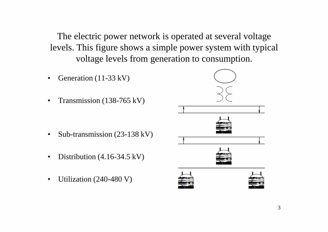
The electric power network is operated at several voltage levels. This figure shows a simple power system with typical
voltage levels from generation to consumption.
• Generation (11-33 kV)
• Transmission (138-765 kV)
• Sub-transmission (23-138 kV)
• Distribution (4.16-34.5 kV)
• Utilization (240-480 V)

4
Actual Electric Utility System

5
Generation and Transmission
• Electricity is typically generated at voltage levels rangingfrom 11 to 33 kVfor three-phase synchronous generators.
• The output voltage of the generator is stepped up totransmission levels in the generating plant substation.
• Usually, power is transferred on transmission lines at avery high voltage in order to reduce energy losses alongthe way (the higher the voltage, the lower the losses).
• Transmission voltages typically range from138 to 765 kV.Currently available are higher voltage overheadtransmission lines for up to 1100 kV.

6
• The three-phase four-wire standard systemis common forAC supply. The supply is standard at 50/60 Hz. There arethree live conductors, each called thephase or line.
• The phase means the relationship of two waveformswith respect to time.
• The voltage between any of these three phases is usually415 V. If a neutral conductor is grounded, then the voltagebetween any phase conductor and the neutral will be 240V. Supplies to premises are always connected to differentphases to balance the load.

7
Single Phase and Three Phase Systems
• If the user is a small one, a house for example, the supply cable willhave two conductors, live and neutral. The supply voltage isusually240/120 V, and such configuration is known as single-phase two-wiresystem.
• The single-phase supply is the most common supply for domesticpremises and other single-occupier premises where the demand forenergy is relatively small.
• Larger consumers receive three-phase four-wire supplies. The highervoltage is generally used for motors and heavy loads. Other smallloads are connected across the outers and the neutral in sucha way thatwhen the whole installation is operating, the load across the threephases is reasonably balanced.

8
Substations!They serve many functions in controlling and transferring power on
electric systems. Several substation layouts are used by electric utilities to achieve reliable system operation. Some of these layouts are used in
large commercial and industrial power systems.
• Substations are main componentsin the power transmission system,which adjust levels of electricityand thereby provide a link with theelectricity supply.
• A substation is an assemblage ofcircuit breakers, disconnectingswitches, and transformersdesigned to change and regulate thevoltage of electricity. Power linescarrying high voltages bring thecurrent from the power plant to thesubstation, where transformersreduce it to lower voltages.
Switchgear Transformer
Meter Meter

Substation
9

10
Power Lines!Overhead power lines are the cheapest method of carrying electrical power. They are usually constructed as parallel wires, which conduct lots of power
very efficiently, but radiate very little.
• Power lines include transmissionlines (mounted on large metaltowers) and distribution lines(mounted on concrete or wood polesplaced on the road reserve).
• Transmission lines carry electricityover long distances and operate atdifferent amounts of voltages andcurrents, usually above 100 kV.
• Distribution lines operate at lowervoltages and bring power fromsubstations to businesses andhomes.

11
See the three lines hanging from a power line!

Electric Utility Distribution Systems
• North America:– 80% of distribution is “13 kv”
– Standards are: 12.47, 13.2, 13.8, and 14.4 kv
– Some use higher: 23, 27, and 33 kv distribution
– Older standards are lower voltages (e.g., 4.16kv)
– Vast majority are wye-grounded.
12

Distribution Design
13

Threads to the Distribution System• Environmental conditions
– Moisture intrusion damage (connectors)
– Mechanical damage (dig in, car hit, people stunts)
– Tree intrusion
– Wildlife intrusion
• Weather (violent)– Wind (more trees into wires, wire stress)
– Lightning
– Ambient heat (“summer heat waves”)
• Electrical– Equipment failures (switches, transformers, communications)
– Overload; carrying fault current at times
• Simple Age and Deterioration– Splice failures (“nothing lasts forever”)
– Equipment failures (transformers, switches, lightning arresters, poles, cable)
• System Operations Consequences– Switching transients
– Out of phase conditions
– Emergency switching (point emergencies, pre-emergencies, load relief, construction
• Anything else you can imagine
14

Distribution System Grounding
• Low ground rod resistance to earth is a the right technique.
• Low ground rod resistance is usually very difficult to achieve.
• Neutral and ground systems are isolated.
• Ground Rod Resistance is Affected by:– Soil resistivity– Ground rod diameter (not too much)– Ground rod length (depth)– Parallel rods
15

Grounding!
16

Transformers
17

18

19

20

21

22

23

24

25

26
From Distribution Lines to Houses via TransformersSource: http://howstuffworks.lycoszone.com/power5.htm

27
Why Three Phase Circuits!• Higher Ratings (horsepower and KVA).
• The power delivered by a single-phase systemfalls to zerothree times during each cycle. However, the powerdelivered by a three-phase circuit never falls to zero.
• In a balanced three-phase system, the conductors need beonly about 75% the size of conductors for single-phase two-wire system.

28
Single- and Three-Phase VoltageSource: Stephen Herman, Electric Circuits for Trades, Thomas Learning.

29
WYE (Star) Connection
phaseline
phaseline
II
VV
=
= 3

30
Delta Connection
PhaseLine
PhaseLine
II
VV
3=
=

31
Example 1: A Y-connected three phase generator (line voltage of 480 V)supplies power to a delta-connected resistive load (8Ω each). Find EL(load),EP(load), and IP(load), IL(load), IL(gen), IP(gen), EP(gen), and the true power..
W8639592.1034803
IE3P
V13.2773
480
3
EE
A92.103I
A92.103360I
A92.103360I
A608
480EI
V 480EE
voltage.line theas same is
voltagephase theload, deltaIn
V 480
r)L(generator)L(generato
r)L(generator)P(generato
r)P(generato
r)L(generato
L(load)
P(load)p(load)
L(load)P(load)
L(load)
=××=
××=
===
=
=×=
=×=
===
==
=
Z
E

32
Example 2: A delta-connected generator is connected to a Y-connectedresistive load. The generator produces a line voltage of 240V and theresistors have a value of 6Ω each. Find, EL(load), EP(load), IP(load), IL(load),IL(gen), IP(gen), EP(gen), and the true power.
W60291.232403IE3P
V 240E
A 13.343
1.23
3
II
A 23.1I
A 23.1I
A 23.16
57.138EI
V 38.5713
240E
V 240E
LL
r)P(generato
r)L(generator)P(generato
r)L(generato
L(load)
P(load)P(load)
P(load)
L(load)
=××=××=
=
===
=
=
===
==
=
Z