Introduction To Number and Computer Systems - …syedatnsu.tripod.com/chap1.pdf · Introduction to...
41
Introduction to Number and Computer Systems Page 1 of 41 Introduction To Number and Computer Systems Rajesh Palit Lecturer Department of Computer Science and Engineering North South University, Dhaka 1213, Bangladesh This is not an original document. It has been compiled from various books and web sites on the internet. The aim of producing these write-ups simply to help the students of ETE 131 course at NSU.
-
Upload
doannguyet -
Category
Documents
-
view
228 -
download
2
Transcript of Introduction To Number and Computer Systems - …syedatnsu.tripod.com/chap1.pdf · Introduction to...

Introduction to Number and Computer Systems
Page 1 of 41
Introduction To
Number and Computer Systems
Rajesh Palit Lecturer
Department of Computer Science and Engineering North South University, Dhaka 1213, Bangladesh
This is not an original document. It has been compiled from various books and web sites on the internet. The aim of producing these write-ups simply to help the students of ETE 131 course at
NSU.

Introduction to Number and Computer Systems
Page 2 of 41
BINARY SYSTEMS Digital systems have such a prominent role in everyday life that we refer to the present technological period as the digital age. Digital systems are used in communication, business transactions, traffic control, space guidance, medical treatment, weather monitoring, the Internet, and many other commercial, industrial, and scientific enterprises. We have digital telephones, digital television, digital versatile discs, digital cameras, and of course, digital computers. The most striking property of the digital computer is its generality. It can follow a sequence of instructions, called a program that operates on given data. The user can specify and change the program or the data according to the specific need. Because of this flexibility, general-purpose digital computers can perform a variety of information processing tasks that range over a wide spectrum of applications. Digital systems manipulate discrete quantities of information that are represented in binary form. Operands used for calculations may be expressed in the binary number system. Other discrete elements, including the decimal digits, are represented in binary codes. Data processing is carried out by means of binary logic elements using binary signals. Quantities are stored in binary storage elements. A decimal number such as 7,392 represents a quantity equal to 7 thousands plus 3 hundreds, plus 9 tens, plus 2 units. The thousands, hundreds, etc. are powers of 10 implied by the position of the coefficients. To be more exact, 7,392 should be written as:
7x10³ + 3x10² + 9x101 + 2x100
However, the convention is to write only the coefficients and from their position deduce the necessary powers of 10. In general, a number with a decimal point is represented by a series of coefficients as follows:
d5 d4 d3 d2 d1 d0.d-1 d-2 d-3
The dj coefficients are any of the 10 digits (0, 1, 2... 9), and the subscript value; gives the place value and, hence, the power of 10 by which the coefficient must be multiplied. This can be expressed as 105dd5 + 104d4 + 103d3 + 102d2 + 101d1 + 100d0 +10-1d-1 + 10-2d-2 + 10-3d-3
The decimal number system is said to be of base, or radix, 10 because it uses 10 digits and the coefficients are multiplied by powers of 10. The binary system is a different number system. The coefficients of the binary numbers system have only two possible values: 0 or 1. Each coefficient d is multiplied by 2n. For example, the decimal equivalent of the binary number 11010.11 is 26.75, as shown from the multiplication of the coefficients by powers of 2:
1x24 + 1x23 + 0x22 + 1x21 + 0x20 + 1x2-1 + 1x2-2 = 26.75

Introduction to Number and Computer Systems
Page 3 of 41
In general, a number expressed in a base-r system has coefficients multiplied by powers of r:
dn.rn + dn-1.rn-1 + . . . + d2.r2 + d1.r1 + d0.r0 + d-1.r-1 + d-2.r-2 + .
. . + d-m.r-m
Where, d0 to dn digits are before the radix point and d-1 to d-m digits are after the radix point. To distinguish between numbers of different bases, we enclose the coefficients in parentheses and write a subscript equal to the base used (except sometimes for decimal numbers, where the content makes it obvious that it is decimal). An example of a base-5 number is
(4021.2)5 = 4x53 + 0x52 + 2x5l + lx50 + 2x5-l = (511.4)10 The coefficient values for base 5 can be only 0, 1, 2, 3, and 4. The octal number system is a base-8 system that has eight digits: 0, 1, 2, 3, 4, 5, 6, 7. An example of an octal number is 127.4. To determine its equivalent decimal value, we expand the number in a power series with a base of 8:
(127.4)8 = 1x82 + 2x81 + 7x80 + 4x8-1 = (87.5)10 Note that the digits 8 and 9 cannot appear in an octal number. It is customary to borrow the needed r digits for the coefficients from the decimal system when the base of the number is less than 10. The letters of the alphabet are used to supplement the 10 decimal digits when the base of the number is greater than 10. For example, in the hexadecimal (base 16) number system, the first ten digits are borrowed from the decimal system. The letters A, B, C, D, E, and F are used for digits 10, 11, 12, 13, 14, and 15, respectively. An example of a hexadecimal number is:
(B65F)16 = 11 x 163 + 6 x 162 + 5 x 161 + 15 x 160 = (46,687)10 As noted before, the digits in a binary number are called bits. When a bit is equal to 0, it does not contribute to the sum during the conversion. Therefore, the conversion from binary to decimal can be obtained by adding the numbers with powers of two corresponding to the bits that are equal to 1. For example,
(110101)2 = 32 + 16 + 4 + 1 = (53)10
There are four 1's in the binary number. The corresponding decimal number is the sum of the four powers of two numbers. In computer work, 210 is referred to as K (kilo), 220 as M (mega), 230 as G (giga), and 240 as T (tera). Thus 4K = 212 = 4096 and 16M = 224 = 16,777,216. Computer capacity is usually given in bytes. A byte is equal to eight bits and can accommodate one keyboard character. A computer hard disk with 4 gigabytes of storage has a capacity of 4G = 232
bytes (approximately 10 billion bytes). Consider base 10 and 2 digit numbers, we have 00 to 99 (100 different numbers). With 3 digits we have 000 to 999, i.e., 1000 numbers. We can say, there are rn different combinations of

Introduction to Number and Computer Systems
Page 4 of 41
numbers for n digits with radix r, by which we can normally represent 0 – (rn-1). The minimum number is 0 and maximum number is (rn -1). If M is a number of n digits with radix r; we can write,
( )
min
1
1
log log( 1)log( 1)
log
log( 1)log
n
n
M
M
n r MM
nr
Mr
rr
n
− ≥
≥ +
≥ ++
≥
+=
To represent a number, M in any base, r we can compute the minimum digits required to express the number. Say for example, we want to represent (729)10 in base 2 and base 16. We need 10 and 3 digits respectively.
2
2
2
2
log(729 1)log2
log730log2
9.5117
10
n
n
nn
+=
=
= =
16
16
16
16
log(729 1)log16
log730log16
2.3779
3
n
n
nn
+=
=
= =
We observe that as the radix increases, the number of required digits decreases. NUMBER BASE CONVERSIONS The conversion of a number in base r to decimal is done by expanding the number in a power series and adding all the terms as shown previously. We now present a general procedure for the reverse operation of converting a decimal number to a number in base r. If the number includes a radix point, it is necessary to separate the number into an integer part and a fraction part, since each part must be converted differently. The conversion of a decimal integer to a number in base r is done by dividing the number and all successive quotients by r and accumulating the remainders. This procedure is best illustrated by example. Convert decimal 41 to binary. First, 41 is divided by 2 to give an integer quotient of 20 and a remainder of ½. The quotient is again divided by 2 to give a new quotient and remainder. This process is continued until the integer quotient becomes 0. The coefficients of the desired binary number are obtained from the remainders as follows:

Introduction to Number and Computer Systems
Page 5 of 41
The arithmetic process can be manipulated more conveniently as follows:
The conversion from decimal integers to any base-r system is similar to the example, except that division is done by r instead of 2. Convert decimal 153 to octal. The required base r is 8. First, 153 is divided by 8 to give an integer quotient of 19 and a remainder of 1. Then 19 is divided by 8 to give an integer quotient of 2 and a remainder of 3. Finally, 2 is divided by 8 to give a quotient of 0 and a remainder of 2. This process can be conveniently manipulated as follows:
The conversion of a decimal fraction to binary is accomplished by a method similar to that used for integers. However, multiplication is used instead of division, and integers are accumulated instead of remainders. Again, the method is best explained by example. Convert (0.6875)io to binary. First, 0.6875 is multiplied by 2 to give an integer and a fraction. The new fraction is multiplied by 2 to give a new integer and a new fraction. This process is continued until the fraction becomes 0 or until the number of digits has sufficient accuracy. The coefficients of the binary number are obtained from the integers as follows:

Introduction to Number and Computer Systems
Page 6 of 41
To convert a decimal fraction to a number expressed in base r, a similar procedure is used. Multiplication is by r instead of 2, and the coefficients found from the integers may range in value from 0 to r - 1 instead of 0 and 1. Convert (0.513)10 to octal.
0.513 X 8 = 4.104 0.104 X 8 = 0.832 0.832 X 8 = 6.656 0.656 X 8 = 5.248 0.248 X 8 = 1.984 0.984 X 8 = 7.872
The answer, to seven significant figures, is obtained from the integer part of the products
(0.513)10 = (0.406517...)8
The conversion of decimal numbers with both integer and fraction parts is done by converting the integer and the fraction separately and then combining the two answers. Using the results of Examples 1-1 and 1-3, we obtain
(41.6875)10 = (101001.1011)2 From Examples 1-2 and 1-4, we have
(153.513)10 = (231.406517)8
OCTAL AND HEXADECIMAL NUMBERS The conversion from and to binary, octal, and hexadecimal plays an important role in digital computers. Since 23 = 8 and 24 = 16, each octal digit corresponds to three binary digits and each hexadecimal digit corresponds to four binary digits. The first 16 numbers in the decimal, binary, octal, and hexadecimal number systems are listed in Table 1-2. The conversion from binary to octal is easily accomplished by partitioning the binary number into groups of three digits each, starting from the binary point and proceeding to the left and to the right. The corresponding octal digit is then assigned to each group. The following example illustrates the procedure:

Introduction to Number and Computer Systems
Page 7 of 41
(10 110 001 101 011 111 100 000 110)2 = (26153.7460)8
2 6 1 5 3 7 4 0 6 Numbers with Different Bases
Decimal (base 10)
Binary (base 2)
Octal (base 8)
Hexadecimal (base 16)
00 0000 00 0 01 0001 01 1 02 0010 02 2 03 0011 03 3 04 0100 04 4 05 0101 05 5 06 0110 06 6 07 0111 07 7 08 1000 10 8 09 1001 11 9 10 1010 12 A 11 1011 13 B 12 1100 14 C 13 1101 15 D 14 1110 16 E 15 1111 17 F
Conversion from binary to hexadecimal is similar, except that the binary number is divided into groups of four digits:
(10 1100 0110 1011. 1111 0010)2 = (2C6B.F2)16 2 C 6 B F 2
The corresponding hexadecimal (or octal) digit for each group of binary digits is easily remembered after studying the values listed in Table 1-2. Conversion from octal or hexadecimal to binary is done by reversing the preceding procedural. Each octal digit is converted to its three-digit binary equivalent. Similarly, each hexadecimal digit is converted to its four-digit binary equivalent. This is illustrated in the following example:
(673.124)8 = (110 111 011. 001 010 100)2
6 7 3 1 2 4 And
(306.D)16 = ( 0011 0000 0110.1101)2
3 0 6 D Binary numbers are difficult to work with because they require three or four times as many digits as their decimal equivalent. For example, the binary number 111111111111 is equivalent to decimal 4095. However, digital computers use binary numbers and it is sometimes necessary for the human operator or user to communicate directly with the machine by means I binary

Introduction to Number and Computer Systems
Page 8 of 41
numbers. One scheme that retains the binary system in the computer, but reduces the number of digits the human must consider, utilizes the relationship between the binary number system and the octal or hexadecimal system. By this method, the human thinks in terms of octal or hexadecimal numbers and performs the required conversion by inspection when direct communication with the machine is necessary. Thus the binary number 111111111111 has 12 digits and is expressed in octal as 7777 (four digits) or in hexadecimal as FFF (three digits). During communication between people (about binary numbers in the computer), the octal or hexadecimal representation is more desirable because it can be expressed more compactly with a third or a quarter of the number of digits required for the equivalent binary number. Thus, most computer manuals use either octal or hexadecimal numbers to specify binary quantities. The choice between them is arbitrary, although hexadecimal tends to win out, since it can represent a byte with two digits. COMPLEMENTS Complements are used in digital computers for simplifying the subtraction operation and for logical manipulation. There are two types of complements for each base-r system: the radix complement and the diminished radix complement. The first is referred to as the r's complement and the second as the (r - l)'s complement. When the value of the base r is substituted in the name, the two types are referred to as the 2's complement and 1's complement for binary numbers, and the 10's complement and 9's complement for decimal numbers. DIMINISHED RADIX COMPLEMENT Given a number N in base r having n digits, the (r - l)'s complement of N is defined as (rn - l) - N. For decimal numbers, r = 10 and r - 1 = 9, so the 9's complement of N is (l0n - l) - N. In this case, 10n represents a number that consists of a single 1 followed by n 0s. 10n - 1 is a number represented by n 9s. For example, if n = 4, we have l04 = 10,000 and l04 - 1 = 9999. It follows that the 9's complement of a decimal number is obtained by subtracting each digit from 9. Some numerical examples follow: The 9's complement of 546700 is 999999 - 546700 = 453299. The 9's complement of 012398 is 999999 - 012398 = 987601. For binary numbers, r = 1 and r - 1 = 1, so the 1's complement of N is (2" - l) - N. Again, 2n is represented by a binary number that consists of a 1 followed by n 0s. 2n - 1 is a binary number represented by n 1's. For example, if n = 4, we have 24 = (10000); and 24 - 1 = (1111)2. Thus the 1's complement of a binary number is obtained by subtracting each digit from 1. However, when subtracting binary digits from 1, we can have either 1- 0 = 1 or 1-1 = 0, which causes the bit to change from 0 to 1 or from 1 to 0. Therefore, the 1's complement of a binary number is formed by changing 1's to 0's and 0's to 1's. The following are some numerical examples:
The 1's complement of 1011000 is 0100111.

Introduction to Number and Computer Systems
Page 9 of 41
The 1's complement of 0101101 is 1010010.
The (r - 1)'s complement of octal or hexadecimal numbers is obtained by subtracting each digit from 7 or F (decimal 15), respectively. RADIX COMPLEMENT The r's complement of an n-digit number N in base r is defined as r" — N, for N ? 0 and 0 for N = 0. Comparing with the (r - l)'s complement, we note that the r's complement is obtained by adding 1 to the (r - l)'s complement since r" - N = [(r" - l) - N] + 1. Thus, the 10's complement of decimal 2389 is 7610 + 1 = 7611 and is obtained by adding 1 to the 9's-complement value. The 2's complement of binary 101100 is 010011 + 1 = 010100 and is obtained by adding 1 to the 1's-complement value. Since 10" is a number represented by a 1 followed by n 0's, 10" — N, which is the 10's complement of N, can be formed also by leaving all least significant 0's unchanged, subtracting the first nonzero least significant digit from 10, and subtracting all higher significant digits from 9.
The 10's complement of 012398 is 987602. The 10's complement of 246700 is 753300.
The 10's complement of the first number is obtained by subtracting 8 from 10 in the least significant position and subtracting all other digits from 9. The 10's complement of the second number is obtained by leaving the two least significant 0's unchanged, subtracting 7 from 10, and subtracting the other three digits from 9. Similarly, the 2's complement can be formed by leaving all least significant 0's and the first 1 unchanged, and replacing 1 's with 0's and 0's with 1 's in all other higher significant digits.
The 2's complement of 1101100 is 0010100. The 2's complement of 0110111 is 1001001.
The 2's complement of the first number is obtained by leaving the two least significant 0's and the first 1 unchanged, and then replacing 1 's with 0's and 0's with 1 's in the other four most-significant digits. The 2's complement of the second number is obtained by leaving the least significant 1 unchanged and complementing all other digits. In the previous definitions, it was assumed that the numbers did not have a radix point. If the original number N contains a radix point, the point should be removed temporarily in order to form the r's or (r - l)'s complement. The radix point is then restored to the complemented number in the same relative position. It is also worth mentioning that the complement of the complement restores the number to its original value. The r's complement of N is rn - N. The complement of the complement is rn - (rn- N) = N, and is equal to the original number.

Introduction to Number and Computer Systems
Page 10 of 41
SIGNED BINARY NUMBERS Positive integers (including zero) can be represented as unsigned numbers. However, to represent negative integers, we need a notation for negative values. In ordinary arithmetic, a negative number is indicated by a minus sign and a positive number by a plus sign. Because of hardware limitations, computers must represent everything with binary digits. It is customary to represent the sign with a bit placed in the leftmost position of the number. The convention is to make the sign bit 0 for positive and 1 for negative. It is important to realize that both signed and unsigned binary numbers consist of a string of bits when represented in a computer. The user determines whether the number is signed or unsigned. If the binary number is signed, then the leftmost bit represents the sign and the rest of the bits represent the number. If the binary number is assumed to be unsigned, then the left-most bit is the most significant bit of the number. For example, the string of bits 01001 can be considered as 9 (unsigned binary) or a +9 (signed binary) because the leftmost bit is 0. The string of bits 11001 represent the binary equivalent of 25 when considered as an unsigned number or as -9 when considered as a signed number. This is because the 1 that is in the leftmost position designates a negative and the other four bits represent binary 9. Usually, there is no confusion in identifying the bits if the type of representation for the number is known in advance. The representation of the signed numbers in the last example is referred to as the signed-magnitude convention. In this notation, the number consists of a magnitude and a symbol (+ or -) or a bit (0 or 1) indicating the sign. This is the representation of signed numbers used in ordinary arithmetic. When arithmetic operations are implemented in a computer, it is more convenient to use a different system for representing negative numbers, referred to as the signed-complement system. In this system, a negative number is indicated by its complement. Whereas the signed-magnitude system negates a number by changing its sign, the signed-complement system negates a number by taking its complement. Since positive numbers always start with 0 (plus) in the left-most position, the complement will always start with a 1, indicating a negative number. The signed-complement system can use either the 1's or the 2's complement, but the 2's complement is the most common. As an example, consider the number 9 represented in binary with eight bits. +9 is represented within a sign bit of 0 in the leftmost position, followed by the binary equivalent of 9, which gives 00001001. Note that all eight bits must have a value and, therefore, 0s are inserted following the sign bit up to the first 1. Although there is only one way to represent +9, there are three different ways to represent -9 with eight bits:
signed-magnitude representation: 10001001 signed-1's-complement representation: 11110110 signed-2's-complement representation: 11110111
In signed-magnitude, -9 is obtained from +9 by changing the sign bit in the leftmost position from 0 to 1. In signed-1's complement, -9 is obtained by complementing all the bits of +9,

Introduction to Number and Computer Systems
Page 11 of 41
including the sign bit. The signed-2's-complement representation of -9 is obtained by taking the 2's complement of the positive number, including the sign bit.
Decimal Slgned-2's complement
Signed-1's complement
Signed magnitude
+7 0111 0111 0111 +6 0110 0110 0110 +5 0101 0101 0101 +4 0100 0100 0100 +3 0011 0011 0011 +2 0010 0010 0010 +1 0001 0001 0001 +0 0000 0000 0000 -0 — 1111 1000 -1 1111 1110 1001 -2 1110 1101 1010 -3 1101 1100 1011 -4 1100 1011 1100 -5 1011 1010 1101 -6 1010 1001 1110 -7 1001 1000 1111 -8 1000 — —
Above table lists all possible 4-bit signed binary numbers in the three representations. The equivalent decimal number is also shown for reference. Note that the positive numbers in all three representations are identical and have 0 in the leftmost position. The signed-2's complement system has only one representation for 0, which is always positive. The other two systems have either a positive 0 or a negative 0, which is something not encountered in ordinary arithmetic. Note that all negative numbers have a 1 in the leftmost bit position; this is the way we distinguish them from the positive numbers. With four bits, we can represent 16 binary numbers. In the signed-magnitude and the 1's complement representations; there are eight positive numbers and eight negative numbers, including two zeros. In the 2's complement representation, there are eight positive numbers, including one zero and eight negative numbers. The signed-magnitude system is used in ordinary arithmetic, but is awkward when employed in computer arithmetic because of the separate handling of the sign and the magnitude. Therefore, the signed-complement is normally used. The 1's complement imposes some difficulties and is seldom used for arithmetic operations. It is useful as a logical operation since the change of 1 to 0 or 0 to 1 is equivalent to a logical complement operation, as will be shown in the next chapter. The following discussion of signed binary arithmetic deals exclusively with the signed-2's-complement representation of negative numbers. The same procedures can be applied to the signed- 1's-complement system by including the end-around carry as done with unsigned numbers.

Introduction to Number and Computer Systems
Page 12 of 41
ARITHMETIC ADDITION The addition of two numbers in the signed-magnitude system follows the rules of ordinary arithmetic. If the signs are the same, we add the two magnitudes and give the sum the common sign. If the signs are different, we subtract the smaller magnitude from the larger and give the result the sign of the larger magnitude. For example, (+25) + (-37) = - (37 - 25) = -12 and is done by subtracting the smaller magnitude 25 from the larger magnitude 37 and using the sign of 37 for the sign of the result. This is a process that requires the comparison of the signs and the magnitudes and then performing either addition or subtraction. The same procedure applies to binary numbers in signed-magnitude representation. In contrast, the rule for adding numbers in the signed-complement system does not require a comparison or subtraction, but only addition. The procedure is very simple and can be stated as follows for binary numbers: The addition of two signed binary numbers with negative numbers represented in signed-2's-complement form is obtained from the addition of the two numbers, including their sign bits. A carry out of the sign-bit position is discarded. Numerical examples for addition follow:
+ 6 00000110 - 6 11111010 +13 00001101 +13 00001101 +19 00010011 + 7 00000111
+ 6 00000110 -6 11111010 -13 11110011 -13 11110011 - 7 11111001 -19 11101101
Note that negative numbers must be initially in 2's complement and that if the sum obtained after the addition is negative, it is in 2's-complement form. In each of the four cases, the operation performed is addition with the sign bit included. Any carry out of the sign-bit position is discarded, and negative results are automatically in 2's-complement form. In order to obtain a correct answer, we must ensure that the result has a sufficient number of bits to accommodate the sum. If we start with two n-bit numbers and the sum occupies n + 1 bits, we say that an overflow occurs. When one performs the addition with paper and pencil, an overflow is not a problem, because we are not limited by the width of the page. We just add another 0 to a positive number or another 1 to a negative number in the most-significant position to extend them to n + 1 bits and then perform the addition. Overflow is a problem in computers because the number of bits that hold a number is finite, and a result that exceeds the finite value by 1 cannot be accommodated. The complement form of representing negative numbers is unfamiliar to those used to the signed-magnitude system. To determine the value of a negative number when in signed-2's complement, it is necessary to convert it to a positive number to place it in a more familiar form.

Introduction to Number and Computer Systems
Page 13 of 41
For example, the signed binary number 11111001 is negative because the leftmost bit is 1- Its 2's complement is 00000111, which is the binary equivalent of +7. We therefore recognize the original negative number to be equal to -7. ARITHMETIC SUBTRACTION Subtraction of two signed binary numbers when negative numbers are in 2's-complement form is very simple and can be stated as follows: Take the 2's complement of the subtrahend (including the sign bit) and add it to the minuend (including the sign bit). A carry out of the sign-bit position is discarded. This procedure occurs because a subtraction operation can be changed to an addition operation if the sign of the subtrahend is changed. This is demonstrated by the following relationship:
(±A) - (+B) = (±A) + (-B) (±A) - (-B) = (±A) + (+B)
But changing a positive number to a negative number is easily done by taking its 2's complement. The reverse is also true because the complement of a negative number in complement form produces the equivalent positive number. Consider the subtraction of (-6) - (-13) = +7. In binary with eight bits, this is written as (11111010 - 11110011). The subtraction is changed to addition by taking the 2's complement of the subtrahend (-13) to give (+13). In binary, this is 11111010 + 00001101 = 100000111. Removing the end carry, we obtain the correct answer: 00000111 (+7). It is worth noting that binary numbers in the signed-complement system are added and subtracted by the same basic addition and subtraction rules as unsigned numbers. Therefore, computers need only one common hardware circuit to handle both types of arithmetic. The user or programmer must interpret the results of such addition or subtraction differently, depending on whether it is assumed that the numbers are signed or unsigned. BINARY LOGIC OPERATIONS
a b a AND b ( a . b)
a OR b ( a + b)
a XOR b ( a + b )
NOT a ( a )
a NAND b ( a . b )
b NOR b ( a + b )
0 0 0 0 0 1 1 1 0 1 0 1 1 1 1 0 1 0 0 1 1 0 1 0 1 1 1 1 0 0 0 0
If A = 1010
B = 0110
A . B = 0010 A + B = 1110
Introduction to Number and Computer Systems
Page 14 of 41
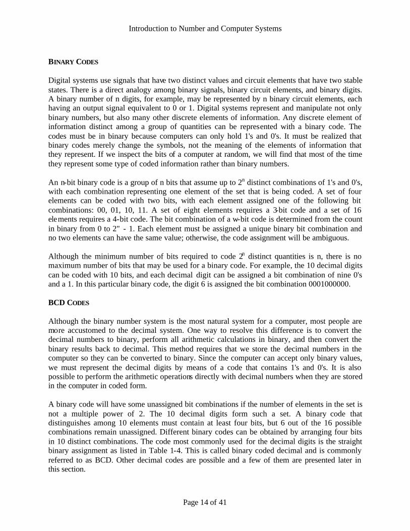
BINARY CODES Digital systems use signals that have two distinct values and circuit elements that have two stable states. There is a direct analogy among binary signals, binary circuit elements, and binary digits. A binary number of n digits, for example, may be represented by n binary circuit elements, each having an output signal equivalent to 0 or 1. Digital systems represent and manipulate not only binary numbers, but also many other discrete elements of information. Any discrete element of information distinct among a group of quantities can be represented with a binary code. The codes must be in binary because computers can only hold 1's and 0's. It must be realized that binary codes merely change the symbols, not the meaning of the elements of information that they represent. If we inspect the bits of a computer at random, we will find that most of the time they represent some type of coded information rather than binary numbers. An n-bit binary code is a group of n bits that assume up to 2n distinct combinations of 1's and 0's, with each combination representing one element of the set that is being coded. A set of four elements can be coded with two bits, with each element assigned one of the following bit combinations: 00, 01, 10, 11. A set of eight elements requires a 3-bit code and a set of 16 elements requires a 4-bit code. The bit combination of a w-bit code is determined from the count in binary from 0 to 2" - 1. Each element must be assigned a unique binary bit combination and no two elements can have the same value; otherwise, the code assignment will be ambiguous. Although the minimum number of bits required to code 2n distinct quantities is n, there is no maximum number of bits that may be used for a binary code. For example, the 10 decimal digits can be coded with 10 bits, and each decimal digit can be assigned a bit combination of nine 0's and a 1. In this particular binary code, the digit 6 is assigned the bit combination 0001000000. BCD CODES Although the binary number system is the most natural system for a computer, most people are more accustomed to the decimal system. One way to resolve this difference is to convert the decimal numbers to binary, perform all arithmetic calculations in binary, and then convert the binary results back to decimal. This method requires that we store the decimal numbers in the computer so they can be converted to binary. Since the computer can accept only binary values, we must represent the decimal digits by means of a code that contains 1's and 0's. It is also possible to perform the arithmetic operations directly with decimal numbers when they are stored in the computer in coded form. A binary code will have some unassigned bit combinations if the number of elements in the set is not a multiple power of 2. The 10 decimal digits form such a set. A binary code that distinguishes among 10 elements must contain at least four bits, but 6 out of the 16 possible combinations remain unassigned. Different binary codes can be obtained by arranging four bits in 10 distinct combinations. The code most commonly used for the decimal digits is the straight binary assignment as listed in Table 1-4. This is called binary coded decimal and is commonly referred to as BCD. Other decimal codes are possible and a few of them are presented later in this section.

Introduction to Number and Computer Systems
Page 15 of 41
The following table gives the 4-bit code for one decimal digit. A number with k decimal digits will require 4k bits in BCD. Decimal 396 is represented in BCD with 12 bits as 0011 1001 0110, with each group of 4 bits representing one decimal digit. A decimal number in BCD is the same as its equivalent binary number only when the number is between 0 and 9.
Decimal symbol
BCD Digit
0 0000 1 0001 2 0010 3 0011 4 0100 5 0101 6 0110 7 0111 8 1000 9 1001
OTHER DECIMAL CODES Binary codes for decimal digits require a minimum of four bits per digit. Many different codes can be formulated by arranging four bits in 10 distinct possible combinations. The BCD and three other representative codes are shown in the table. Each code uses only 10 bit combinations out of possible 16 combinations that can be arranged with four bits. The other six unused combinations in each case have no meaning and should be avoided; The BCD and the 2421 codes are examples of weighted codes. In a weighted code, each bit position is assigned a weighting factor in such a way that each digit can be evaluated by adding the weights of all the 1's in the coded combination. The BCD code has weights of 8, 4, 2, and 1, which correspond to the power of two values of each bit. The bit assignment 0110 for example, is interpreted by the weights to represent decimal 6 because 8x0 + 4x1 + 2x1 + 1x0 = 6. The bit combination 1101 when weighted by the respective digits 2421 gives:
Four Different Binary Codes for the Decimal Digits Decimal
Digit BCD 8421
2421
Excess – 3
8 4 -2 -1
0 0000 0000 0011 0000 1 0001 0001 0100 0111 2 0010 0010 0101 0110 3 0011 0011 0110 0101 4 0100 0100 0111 0100 5 0101 1011 1000 1011 6 0110 1100 1001 1010 7 0111 1101 1010 1001 8 1000 1110 1011 1000 9 1001 1111 1100 1111

Introduction to Number and Computer Systems
Page 16 of 41
GRAY CODE ASCII CODE ERROR DETECTING CODE To detect errors in data communication and processing, an eighth bit is sometimes added to the ASCII character to indicate its parity. A parity bit is an extra bit included with a message to make the total number of 1's either even or odd. Consider the following two characters and their even and odd parity: With even parity With odd parity
ASCII A = 1000001 01000001 11000001 ASCII T = 1010100 11010100 01010100
In each case, we insert an extra bit in the leftmost position of the code to produce an even number of 1's in the character for even parity or an odd number of 1's in the character for odd parity. In general, one or the other parity is adopted, with even parity being more common. The parity bit is helpful in detecting errors during the transmission of information from one location to another. This is handled by generating an even parity bit in the sending end for each character. The 8-bit characters that include parity bits are transmitted to their destination. The parity of each character is then checked in the receiving end. If the parity of the received character is not even, it means that at least one bit has changed value during the transmission. This method detects one, three, or any odd combination of errors in each character that is transmitted. An even combination of errors is undetected. Additional error detection codes may be needed to take care of an even combination of errors. What is done after an error is detected depends on the particular application. One possibility is to request retransmission of the message on the assumption that the error was random and will not occur again. Thus, if the receiver detects a parity error, it sends back the ASCII NAK (negative acknowledge) control character consisting of an even parity eight bits 10010101. If no error is detected, the receiver sends back an ACK (acknowledge) control character, 00000110. The sending end will respond to an NAK by transmitting the message again until the correct parity is received. If, after a number of attempts, the transmission is still in error, a message can be sent to the operator to check for malfunctions in the transmission path.

Introduction to Number and Computer Systems
Page 17 of 41
Floating Point Numbers IEEE Standard 754 floating point is the most common representation today for real numbers on computers, including Intel-based PC's, Macintoshes, and most Unix Platforms. There are several ways to represent real numbers on computers. Fixed point places a radix point somewhere in the middle of the digits, and is equivalent to using integers that represent portions of some unit. For example, one might represent 1/100ths of a unit; if you have four decimal digits, you could represent 10.82, or 00.01. Another approach is to use rationals, and represent every number as the ratio of two integers. Floating-point representation - the most common solution - basically represents reals in scientific notation. Scientific notation represents numbers as a base number and an exponent. For example, 123.456 could be represented as 1.23456 x 10². In hexadecimal, the number 123.abc might be represented as 1.23abc x 162. Floating-point solves a number of representation problems. Fixed-point has a fixed window of representation, which limits it from representing very large or very small numbers. Also, fixed-point is prone to a loss of precision when two large numbers are divided. Floating-point, on the other hand, employs a sort of "sliding window" of precision appropriate to the scale of the number. This allows it to represent numbers from 1,000,000,000,000 to 0.0000000000000001 with ease. Storage Layout IEEE floating point numbers have three basic components: the sign, the exponent, and the mantissa. The mantissa is composed of the fraction and an implicit leading digit. The exponent base (2) is implicit and need not be stored. The following figure shows the layout for IEEE 754 single (32-bit) and double (64-bit) precision floating-point values. The number of bits for each field are shown (bit ranges are in square brackets):
Sign Exponent Mantissa Bias Single Precision 1 [31] 8 [30 - 23] 23 [22-0] 127 Double Precision 1 [63] 11 [62 – 52] 52 [51 – 0] 1023
The Sign Bit The sign bit is as simple as it gets. 0 denotes a positive number; 1 denotes a negative number. Flipping the value of this bit flips the sign of the number. The Exponent The exponent field needs to represent both positive and negative exponents. To do this, a bias is added to the actual exponent in order to get the stored exponent. For IEEE single-precision floats, this value is 127. Thus, an exponent of zero means that 127 is stored in the exponent field.

Introduction to Number and Computer Systems
Page 18 of 41
A stored value of 200 indicates an exponent of (200-127), or 73. For reasons discussed later, exponents of -127 (all 0s) and +128 (all 1s) are reserved for special numbers. For double precision, the exponent field is 11 bits, and has a bias of 1023. The Mantissa The mantissa, also known as the significant, represents the precision bits of the number. It is composed of an implicit leading bit and the fraction bits. To find out the value of the implicit leading bit, consider that any number can be expressed in scientific notation in many different ways. For example, the number five can be represented as any of these:
5.00 x 100 0.05 x 10² 5000 x 10-3
In order to maximize the quantity of represent-able numbers, floating-point numbers are typically stored in normalized form. This basically puts the radix point after the first non-zero digit. In normalized form, five is represented as 5.0 x 100. A nice little optimization is available to us in base two, since the only possible nonzero digit is 1. Thus, we can just assume a leading digit of 1, and don't need to represent it explicitly. As a result, the mantissa has effectively 24 bits of resolution, by way of 23 fraction bits. Normalized Form
1. The sign bit is 0 for positive, 1 for negative. 2. The exponent's base is two. 3. The exponent field contains 127 plus the true exponent for single -precision, or 1023 plus the true
exponent for double precision. 4. The first bit of the mantissa is typically assumed to be 1.f, where f is the field of fraction bits.
There are five distinct numerical ranges that single-precision floating-point numbers are not able to represent:
1. Negative numbers less than -(2-2-23) x 2127 (negative overflow) 2. Negative numbers greater than -2-149 (negative underflow) 3. Zero 4. Positive numbers less than 2-149 (positive underflow) 5. Positive numbers greater than (2-2-23) x 2127 (positive overflow)

Introduction to Number and Computer Systems
Page 19 of 41
Special Values IEEE reserves exponent field values of all 0s and all 1s to denote special values in the floating-point scheme. Zero As mentioned above, zero is not directly represent-able in the straight format, due to the assumption of a leading 1 (we'd need to specify a true zero mantissa to yield a value of zero). Zero is a special value denoted with an exponent field of zero and a fraction field of zero. Note that -0 and +0 are distinct values, though they both compare as equal. Infinity The values +infinity and -infinity are denoted with an exponent of all 1s and a fraction of all 0s. The sign bit distinguishes between negative infinity and positive infinity. Being able to denote infinity as a specific value is useful because it allows operations to continue past overflow situations. Operations with infinite values are well defined in IEEE floating point. Not A Number The value NaN (Not a Number) is used to represent a value that does not represent a real number. NaN's are represented by a bit pattern with an exponent of all 1s and a non-zero fraction. There are two categories of NaN: QNaN (Quiet NaN) and SNaN (Signalling NaN). A QNaN is a NaN with the most significant fraction bit set. QNaN's propagate freely through most arithmetic operations. These values pop out of an operation when the result is not mathematically defined. An SNaN is a NaN with the most significant fraction bit clear. It is used to signal an exception when used in operations. SNaN's can be handy to assign to un- initialized variables to trap premature usage. Semantically, QNaN's denote indeterminate operations, while SNaN's denote invalid operations.
IEEE 754 Floating point number Representations Normalized Form
For single precision floating point numbers (32 bits), bias (b) is 127 and double precision floating point
numbers (64 bits), bias (b) is 1023
Sign Exponent (e) Fraction/Mantissa (f) Value Normalized Form
0 000…000 000….000 + 0 0 111…111 000…000 + 8
0 000…001 …
xxx…xxx + 1.f x 2(e-b)
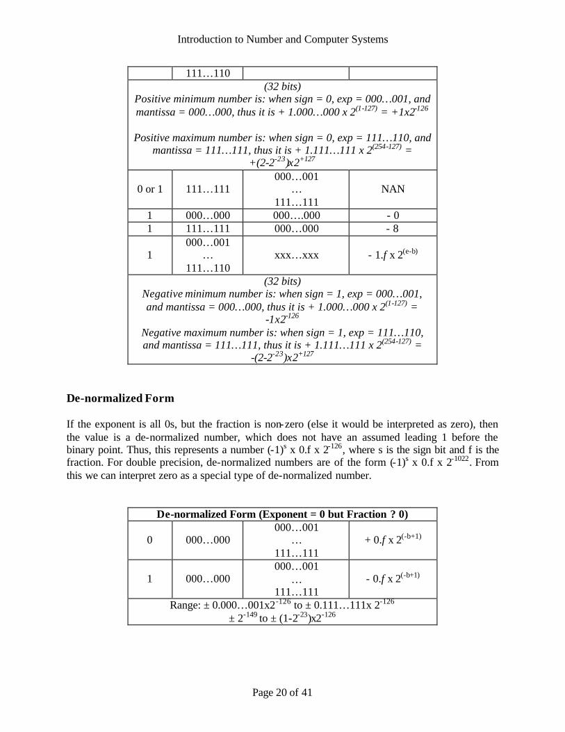
Introduction to Number and Computer Systems
Page 20 of 41
111…110 (32 bits)
Positive minimum number is: when sign = 0, exp = 000…001, and mantissa = 000…000, thus it is + 1.000…000 x 2(1-127) = +1x2-126
Positive maximum number is: when sign = 0, exp = 111…110, and
mantissa = 111…111, thus it is + 1.111…111 x 2(254-127) = +(2-2-23)x2+127
0 or 1 111…111 000…001
… 111…111
NAN
1 000…000 000….000 - 0 1 111…111 000…000 - 8
1 000…001
… 111…110
xxx…xxx - 1.f x 2(e-b)
(32 bits) Negative minimum number is: when sign = 1, exp = 000…001, and mantissa = 000…000, thus it is + 1.000…000 x 2(1-127) =
-1x2-126 Negative maximum number is: when sign = 1, exp = 111…110, and mantissa = 111…111, thus it is + 1.111…111 x 2(254-127) =
-(2-2-23)x2+127 De-normalized Form If the exponent is all 0s, but the fraction is non-zero (else it would be interpreted as zero), then the value is a de-normalized number, which does not have an assumed leading 1 before the binary point. Thus, this represents a number (-1)s x 0.f x 2-126, where s is the sign bit and f is the fraction. For double precision, de-normalized numbers are of the form (-1)s x 0.f x 2-1022. From this we can interpret zero as a special type of de-normalized number.
De-normalized Form (Exponent = 0 but Fraction ? 0)
0 000…000 000…001
… 111…111
+ 0.f x 2(-b+1)
1 000…000 000…001
… 111…111
- 0.f x 2(-b+1)
Range: ± 0.000…001x2-126 to ± 0.111…111x 2-126 ± 2-149 to ± (1-2-23)x2-126

Introduction to Number and Computer Systems
Page 21 of 41
The range of positive floating point numbers can be split into normalized numbers (which preserve the full precision of the mantissa), and de-normalized numbers which use only a portion of the fraction's precision. Since the sign of floating point numbers is given by a special leading bit, the range for negative numbers is given by the negation of the above values.
Denormalized Normalized Approximate
Decimal
Single Precision ± 2-149 to (1-2-23)×2-126 ± 2-126 to (2-2-23)×2127 ± ~10-44.85 to ~1038.53
Double Precision ± 2-1074 to (1-2-52)×2-1022 ± 2-1022 to (2-2-52)×21023 ± ~10-323.3 to ~10308.3

Introduction to Number and Computer Systems
Page 22 of 41
Special Operations
Operation Result
n ÷ ±Infinity 0
±Infinity × ±Infinity ±Infinity
±nonzero ÷ 0 ±Infinity
Infinity + Infinity Infinity
±0 ÷ ±0 NaN
Infinity - Infinity NaN
±Infinity ÷ ±Infinity NaN
±Infinity × 0 NaN
Introduction to Number and Computer Systems
Page 23 of 41
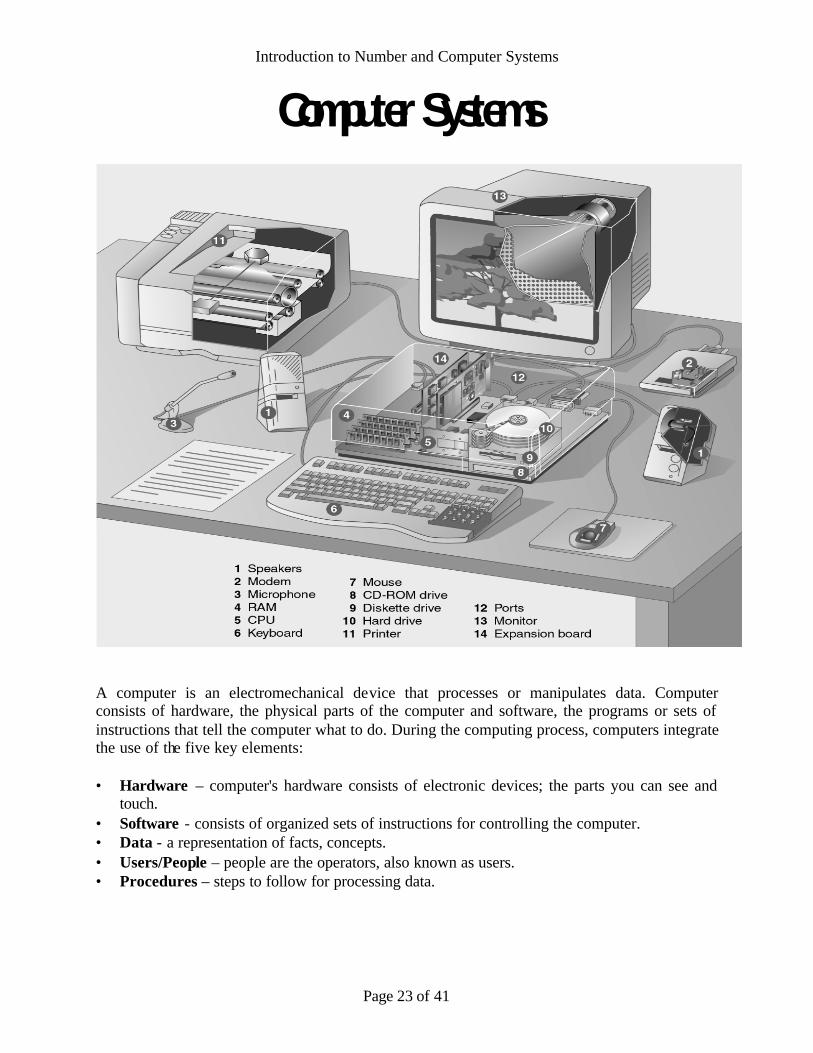
Computer Systems
A computer is an electromechanical device that processes or manipulates data. Computer consists of hardware, the physical parts of the computer and software, the programs or sets of instructions that tell the computer what to do. During the computing process, computers integrate the use of the five key elements: • Hardware – computer's hardware consists of electronic devices; the parts you can see and
touch. • Software - consists of organized sets of instructions for controlling the computer. • Data - a representation of facts, concepts. • Users/People – people are the operators, also known as users. • Procedures – steps to follow for processing data.

Introduction to Number and Computer Systems
Page 24 of 41
A computer normally performs only four basic operations that is often referred as the IPOS cycle. The four steps of the IPOS cycle are:
1. Input 2. Processing 3. Output 4. Storage
Input Devices
• Keyboards • Mouse • Pens • Touch Screens • Game Controllers • Bar Code Readers • Scanners • Optical Character Reader (OCR) • Microphones • Digital Cameras
Processing The processor is like the brain of the computer; it organizes and carries out instructions that come from either the user or the software.

Introduction to Number and Computer Systems
Page 25 of 41
A processor is usually a single chip or a set of chips contained on a circuit board knows as main board or mother board. The term central processing unit (CPU) refers to a computer’s processor.
Intel Pentium 4 processor
The two main parts of a CPU are the control unit and the arithmetic logic unit (ALU). The control unit directs the flow of data through the CPU, and to and from other devices. It stores the CPU's microcode, which contains the instructions for all the tasks the CPU can perform. The actual manipulation of data takes place in the ALU. The ALU can perform arithmetic and logic operations. The ALU is connected to a set of registers—small memory areas in the CPU, which hold data and program instructions while they are being processed. Random Access Memory (RAM) Read Only Memory (ROM)

Introduction to Number and Computer Systems
Page 26 of 41
Output Devices
• Monitors o CRT Monitors o LCD Monitors
• Digital Light Projectors • Speakers • Printers
o Dot matrix o Ink Jet o Laser
• Plotters Storage Devices Magnetic drive Optical dives (CD ROM, DVD)

Introduction to Number and Computer Systems
Page 27 of 41
Internal Structure of Hard disk
Evolution of Computer Systems
1946 AD – J. Presper Eckert, John Mauchley and a team of 50 complete the Electronic Numerical Integrator and Computer (Eniac), the first large-scale electronic digital computer, at the University of Pennsylvania’s Moore School. Weighing 2 tons, standing 2 stories and covering 15,000 square feet, Eniac operates at 357 multiplications per second. Cost: US$ 500, 000 1950 AD – Von Neumann’s EDVAC is finally complete. Having lost the distinction as the first stored-program computer, it is still the first to use binary or digital mathematics. 1954 AD – Fortran, or Formula Translation programming language, is developed by John Bakus at IBM. 1960 AD – The first modern computer generation ends as vacuum tubes, punched cards and machine codes give way to second generation transistors, magnetic tape and procedural languages in computer design and operation.

Introduction to Number and Computer Systems
Page 28 of 41
1965 AD – Beginner’s All-purpose Symbolic Instruction Code (BASIC) language is created by Tom Kurtz and John Kemeny of Darmouth. 1971 AD – Intel markets the 4004 microprocessor, which paves the way for the micro revolution. 1981 AD – The IBM Personal Computer debuts, and Microsoft’s S-DOS becomes its standard operating software. 1990 AD – Computers containing a million processors are set to work solving complex problems. 2000 AD – Computers containing a billion processors exceed the power of the human brain.
Types of Computers Computers come in a variety of types designed for different purposes, with different capabilities and costs.
Microcomputers A microcomputer is a computer that has a microprocessor chip as its CPU. They are often called personal computers (PC) because they are designed to be used by one person at a time. Personal computers are typically used at home, at school, or at a business. Popular uses for microcomputers include word processing, surfing the web, sending and receiving e-mail, spreadsheet calculations, database management, editing photographs, creating graphics, and playing music or games.
Personal computers come in two major varieties, desktop computers and laptop computers: Desktop computers are larger and not meant to be portable. They usually sit in one place on a desk or table and are plugged into a wall outlet for power. The case of the computer holds the motherboard, drives, power supply, and expansion cards. This case may lay flat on the desk, or it may be a tower that stands vertically (on the desk or under it). The computer usually has a separate monitor (either a CRT or LCD) although some designs have a display built into the case. A separate keyboard and mouse allow the user to input data and commands.
Desktop personal computer

Introduction to Number and Computer Systems
Page 29 of 41
Laptop or notebook computers are small and lightweight enough to be carried around with the user. They run on battery power, but can also be plugged into a wall outlet. They typically have a built- in LCD display that folds down to protect the display when the computer is carried around. They also feature a built- in keyboard and some kind of built- in pointing device (such as a touch pad).
While some laptops are less powerful than typical desktop machines, this is not true in all cases. Laptops, however, cost more than desktop units of equivalent processing power because the smaller components needed to build laptops are more expensive.
Laptop personal computer
PDAs and Palmtop Computers A Personal Digital Assistant (PDA) is a handheld microcomputer that trades off power for small size and greater portability. They typically use a touch-sensitive LCD screen for both output and input (the user draws characters and presses icons on the screen with a stylus). PDAs communicate with desktop computers and with each other either by cable connection, infrared (IR) beam, or radio waves. PDAs are normally used to keep track of appointment calendars, to-do lists, address books, and for taking notes.
Personal Digital Assistant
A palmtop or handheld PC is a very small microcomputer that also sacrifices power for small size and portability. These devices typically look more like a tiny laptop than a PDA, with a flip-up screen and small keyboard. They may use Windows CE or similar operating system for handheld devices.
Some PDAs and palmtops contain wireless networking or cell phone devices so that users can check e-mail or surf the web on the move.

Introduction to Number and Computer Systems
Page 30 of 41
Palmtop computer Workstations (Entry level Servers/Workgroup Servers) A workstation is a powerful, high-end microcomputer. They contain one or more microprocessor CPUs. They may be used by a single-user for applications requiring more power than a typical PC (rendering complex graphics, or performing intensive scientific calculations).
Alternately, workstation-class microcomputers may be used as server computers that supply files to client computers over a network. This class of powerful microcomputers can also be used to handle the processing for many users simultaneously who are connected via terminals; in this respect, high-end workstations have essentially supplanted the role of minicomputers (see below).
The term “workstation” also has an alternate meaning: In networking, any client computer connected to the network that accesses server resources may be called a workstation. Such a network client workstation could be a personal computer or even a “workstation” as defined at the top of this section. Dumb terminals (Sun Thin Clients) are not considered to be network workstations. Client workstations on the network are capable of running programs independently of the server, but a terminal is not capable of independent processing.
Workstation computer
There are classes of computers that are not microcomputers. These include supercomputers, mainframes, and minicomputers.

Introduction to Number and Computer Systems
Page 31 of 41
Minicomputers (Mid-Range/High-End Servers) A minicomputer is a multi-user computer that is less powerful than a mainframe. This class of computers became available in the 1960’s when large scale integrated circuits made it possible to build a computer much cheaper than the then existing.
Sun Fire V490 Server
Mainframes A mainframe computer is a large, powerful computer that handles the processing for many users simultaneously (up to several hundred users). The name mainframe originated after minicomputers appeared in the 1960’s to distinguish the larger systems from the smaller minicomputers.
Users connect to the mainframe using terminals and submit their tasks for processing by the mainframe. A terminal is a device that has a screen and keyboard for input and output, but it does not do its own processing (they are also called dumb terminals since they can’t process data on their own). The processing power of the mainframe is time-shared between all of the users.
Mainframes typically cost several hundred thousand dollars. They are used in situations where a company wants the processing power and information storage in a centralized location. Mainframes are also now being used as high-capacity server computers for networks with many client workstations.
Mainframe computer (this IBM z-series is about 6 feet tall)

Introduction to Number and Computer Systems
Page 32 of 41
Supercomputers A supercomputer is mainframe computer that has been optimized for speed and processing power. The most famous series of supercomputers were designed by the company founded and named after Seymour Cray. The Cray-1 was built in the 1976 and installed at Los Alamos National Laboratory. Supercomputers are used for extremely calculation-intensive tasks such simulating nuclear bomb detonations, aerodynamic flows, around global weather patterns. A supercomputer typically costs several million dollars.
Recently, some supercomputers have been constructed by connecting together large numbers of individual processing units (in some cases, these processing units are standard microcomputer hardware).
All of this talk of which computers are more powerful than others (i.e., mainframes are more powerful than minicomputers, which are more powerful than microcomputers) is relative for any particular moment in time. However, all classes of computers are becoming more powerful with time as technology improves. The microprocessor chip in a handheld calculator is more powerful than the ENIAC was, and your desktop computer has more processing power than the first supercomputers.
Earth Simulator, Japan
Rank Site
Country/Year Computer / Processors
Manufacturer Rmax Rpeak
1 Earth Simulator Center Japan/2002
Earth-Simulator / 5120 NEC
35860 40960
2 Lawrence Livermore National Laboratory United States/2004
Thunder Intel Itanium2 Tiger4 1.4GHz -
Quadrics / 4096 California Digital Corporation
19940 22938
3 Los Alamos National
Laboratory United States/2002
ASCI Q - AlphaServer SC45, 1.25 GHz / 8192
HP
13880 20480

Introduction to Number and Computer Systems
Page 33 of 41
Computer - Type indicated by manufacturer or vendor
Processors - Number of processors Rmax - Maximal LINPACK performance achieved
Rpeak - Theoretical peak performance
FLOPS is acronym for FLoating-point Operations Per Second. For example, 15 Mflops equals 15 million floating-point arithmetic operations per second. Flops is used as a measure of a computing system's speed of performing basic arithmetic operations such as adding, subtracting, multiplying, or dividing two numbers. It usua lly refers to addition and subtractions which are the fastest operations. Multiplication and especially division may be significantly slower (less FLOPS). GFLOPS stands for Giga FLOPS, TFLOPS stands for Tera FLOPS. The LINPACK Benchmark is based on LINPACK, representing a measure of a system's floating point computing power. Introduced by Jack Dongarra, it measures how fast a computer solves dense n by n systems of linear equations. The result is millions of floating point operations per second (Mflops). CPUs Used in Personal Computers
• Intel Processors • AMD Processors • Cyrix Processors • Motorola Processors • RISC Processors
Intel Processors Since 1978, Intel's processors have evolved from the 8086 and the 8088 to the 80286, 80386, and 80486, to the Pentium family of processors. All are part of the 80x86 line. Intel's Pentium family of processors includes the Pentium, Pentium Pro, Pentium with MMX, Pentium II to Pentium IV, Celeron, and Xeon processors. The earliest Intel processors included only a few thousand transistors. Today's Pentium processors include 9.5 million transistors or more.

Introduction to Number and Computer Systems
Page 34 of 41
AMD Processors Advanced Micro Devices (AMD) was long known as a provider of lower-performance processors for use in low-cost computers. With its K6 line of processors, AMD challenged Intel's processors in terms of both price and performance. With the K6-III processor, AMD broke the 600 MHz barrier, claiming the "fastest processor" title for the first time in IBM-compatible computers. Cyrix Processors Cyrix began as a specialty chip maker, but eventually began producing microprocessors. Cyrix processors are most commonly used in low-price, low-end consumer PCs. Cyrix formerly produced the MediaGX processor, and now produces the MII series of processors.
Motorola Processors Motorola makes the CPUs used in Macintosh and PowerPC computers. Macintosh processors use a different basic structural design (architecture) than IBM-compatible PC processors. With the release of the G3 and G4 PowerPC processors, Macintosh computers set new standards for price and performance. RISC Processors Most PCs are based on complex instruction set computing (CISC) chips which contain large instruction sets. One CISC instruction consists of several simple instructions. Reduced

Introduction to Number and Computer Systems
Page 35 of 41
instruction set computing (RISC) processors use smaller instruction sets. This enables them to process more instructions per second than (CISC) chips. RISC processors are found in Apple's PowerPC systems, as well as many Handheld PCs (H/PCs), workstations, minicomputers, and mainframes. Parallel Processing In parallel processing, multiple processors are used in a single system, enabling them to share processing tasks. In a massively parallel processor (MPP) system, many processors are used. Some MPP systems utilize thousands of processors simultaneously.
Memory Computers use RAM (Random Access Memory) to hold the program code and data during computation. A defining characteristic of RAM is that all memory locations can be accessed at almost the same speed. Most other techno logies have inherent delays for reading a particular bit or byte. Many types of RAM are volatile, which means that unlike some other forms of computer storage such as disk storage and tape storage; they lose all data when the computer is powered down. Modern RAM generally stores a bit of data as either a charge in a capacitor, as in "dynamic RAM,", or the state of a flip-flop, as in "static RAM". Extended Data Out (EDO) Dynamic Random Access Memory, a type of DRAM that is faster than conventional DRAM. Unlike conventional DRAM which can only access one block of data at a time, EDO RAM can start fetching the next block of memory at the same time that it sends the previous block to the CPU. Single in- line memory module (SIMM) Dual in- line memory module (DIMM) SDRAM (Synchronous DRAM) Almost all systems used to ship with 3.3 volt, 168-pin SDRAM DIMMs. SDRAM is not an

Introduction to Number and Computer Systems
Page 36 of 41
extension of older EDO DRAM but a new type of DRAM altogether. SDRAM started out running at 66 MHz, while older fast page mode DRAM and EDO max out at 50 MHz. SDRAM is able to scale to 133 MHz (PC133) officially, and unofficially up to 180MHz or higher. As processors get faster, new generations of memory such as DDR and RDRAM are required to get proper performance. DDR (Double Data Rate SDRAM) DDR basically doubles the rate of data transfer of standard SDRAM by transferring data on the up and down tick of a clock cycle. DDR memory operating at 333MHz actually operates at 166MHz * 2 (aka PC333 / PC2700) or 133MHz*2 (PC266 / PC2100). DDR is a 2.5 volt technology that uses 184 pins in its DIMMs. It is incompatible with SDRAM physically, but uses a similar parallel bus, making it easier to implement than RDRAM, which is a different technology.
SIMM
DIMM Memory Speed SDRAM initially shipped at a speed of 66MHz. As memory buses got faster, it was pumped up to 100MHz, and then 133MHz. The speed grades are referred to as PC66 (unofficially), PC100 and PC133 SDRAM respectively. Some manufacturers are shipping a PC150 speed grade. The speed of DDR RAM is above 400 MHz. Cache Memory Cache Memory is fast memory that serves as a buffer between the processor and main memory. The cache holds data that was recently used by the processor and saves a trip all the way back to slower main memory. The memory structure of PCs is often thought of as just main memory, but it's really a five or six level structure:

Introduction to Number and Computer Systems
Page 37 of 41
The first two levels of memory are contained in the processor itself, consisting of the processor's small internal memory, or registers, and L1 cache, which is the first level of cache, usually contained in the processor. The third level of memory is the L2 cache, usually contained on the motherboard. However, the Celeron chip from Intel actually contains 128K of L2 cache within the form factor of the chip. More and more chip makers are planning to put this cache on board the processor itself. The benefit is that it will then run at the same speed as the processor, and cost less to put on the chip than to set up a bus and logic externally from the processor. The fourth level, is being referred to as L3 cache. This cache used to be the L2 cache on the motherboard, but now that some processors include L1 and L2 cache on the chip, it becomes L3 cache. Usually, it runs slower than the processor, but faster than main memory. The fifth level (or fourth if you have no "L3 cache") of memory is the main memory itself. The sixth level is a piece of the hard disk used by the Operating System, usually called virtual memory. Most operating systems use this when they run out of main memory, but some use it in other ways as well. This six- tiered structure is designed to efficiently speed data to the processor when it needs it, and also to allow the operating system to function when levels of main memory are low. You might ask, "Why is all this necessary?" The answer is cost. If there were one type of super- fast, super-cheap memory, it could theoretically satisfy the needs of this entire memory architecture. This will probably never happen since you don't need very much cache memory to drastically improve performance, and there will always be a faster, more expensive alternative to the current form of main memory. Bits, bytes and words Computer memory consists of a large number of 'two-state devices' (flip-flops). We can think of them as switches, which can be 'On' or 'Off'. If the switch is 'On' it is storing the digit 1. If the switch is 'Off' it is storing the number 0. Hence the binary system of numbers is used, which consists only of numbers containing 0s and 1s.
This is how the computer would store the binary number 1011

Introduction to Number and Computer Systems
Page 38 of 41
A bit (Binary digIT) is a 0 or a 1. So 1011 is a 4-bit binary number. All data (text, pictures, sounds, video clips etc) is stored as binary numbers. The left-end bit of a number represented in binary is called the most significant bit, abbreviated msb, and the right-end bit is called the least significant bit, abbreviated lsb.
8 bits (b) = 1 byte (B) 1024 bytes = 1 kilobyte (KB) 1024 kilobytes = 1 megabyte (MB) 1024 megabytes = 1 gigabyte (GB) 1024 gigabytes = 1 terabyte (TB)
A word is the number of bits that the CPU can handle at a time (usually 16, 32, 64 or 128). When we say 32 bit processor, the word size is 32 bits. Software Computer software is that part of a computer system that consists of encoded information (or computer instructions), as opposed to the physical computer equipment (hardware) which is used to store and process this information. The term is roughly synonymous with computer program but is more generic in scope. System, programming and application software Practical computer systems divide software into three major classes: system software, programming software and application software, although the distinction is somewhat arbitrary, and often blurred.
• System software helps run the computer hardware and computer system. It includes operating systems, device drivers, diagnostic tools, servers, windowing systems, utilities and more. The purpose of systems software is to insulate the applications programmer as much as possible from the details of the particular computer complex being use, especially memory and other hardware features, and such accessory devices as communications, printers, readers, displays, keyboards, etc.
• Programming software usually provides tools to assist a programmer in writing
computer programs and software using different programming languages in a more convenient way. The tools include text editors, compilers, interpreters, linkers, debuggers, and so on. An Integrated development environment (IDE) merges those tools into a software bundle, and a programmer may not need to type multiple commands for compiling, interpreter, debugging, tracing, and etc., because the IDE usually has an advanced graphical user interface, or GUI.
• Application software allows humans to accomplish one or more specific (non-computer
related) tasks. Typical applications include industrial automation, business software, educational software, medical software, databases and computer games. Businesses are

Introduction to Number and Computer Systems
Page 39 of 41
probably the biggest users of application software, but almost every field of human activity now uses some form of application software.
Operating Systems An operating system (OS) is an essential software program that manages the hardware and software resources of a computer. The OS performs basic tasks, such as controlling and allocating memory, prioritizing the processing of instructions, controlling input and output devices, facilitating networking and managing files.
• The User Interface • Running Programs • Managing Files • Managing Hardware • Utility Software
Graphical User Interfaces (GUIs) - GUI Tools, Applications and the Interface, Menus, Dialog Boxes, Command-Line Interfaces; General-purpose computers, including personal computers and mainframes, must have an operating system to run other programs, such as application software. Examples of operating systems for personal computers include Microsoft Windows, Mac OS, Unix, and Linux. The lowest level of any operating system is its kernel. This is the first layer of software loaded into memory when a system boots or starts up. The kernel provides access to various common core services to all other system and application programs. These services include, but are not limited to: disk access, memory management, task scheduling, and access to other hardware devices. As well as the kernel, an operating system is often distributed with tools for programs to display and manage a graphical user interface, as well as utility programs for tasks such as managing files and configuring the operating system. They are also often distributed with application software that does not relate directly to the operating system's core function, but which the operating system distributor finds advantageous to supply with the operating system. Today’s OS Command line interface (or CLI) OS's such as DOS, use only the keyboard for input. Modern OS's use a mouse for input with a graphical user interface (GUI) sometimes implemented as a shell. The appropriate OS may depend on the hardware architecture, specifically the CPU, with only Linux and BSD running on almost any CPU. Since the early 1990s the choice for personal computers has been largely limited to the Microsoft Windows family and the Unix- like family, of which Linux and Mac OS X are becoming the major choices. Mainframe computers and embedded systems use a variety of different operating systems, many with no direct connection to Windows or Unix, but typically more similar to Unix than Windows.

Introduction to Number and Computer Systems
Page 40 of 41
IBM PC compatible - Microsoft Windows and smaller Unix-variants (like Linux and BSD) Apple Macintosh - Mac OS X, Windows, Linux and BSD Mainframes - A number of unique OS's, sometimes Linux and other UNIX variants Embedded systems - a variety of dedicated OS's, and limited versions of Linux or other OS's [Multi-tasking, multi-programming, multi-processing, parallel processing, multi-
threading, distributed processing] Computer Programs The program tells the CPU to process interrupts, or sets of steps the CPU must follow to perform a task. Computer hardware understands only machine code. To control hardware, a program must be written in binary numbers (1s and 0s). This code is called machine code or machine language. Programmers use programming languages to write code in nearly human language. The resulting description is called source code. Compilers and interpreters translate a program into object code, the binary version of source code. The order in which program statements are executed is called program control flow. To determine program control flow, programmers may use a flowchart to map the program's sequence. Programmers may also create a simple text version of a program's code – called pseudo code – to determine how the program will flow. Programming Languages The first widely used high- level programming language was FORTRAN, developed during 1954–57 by an IBM team led by John W. Backus. It is still widely used for numerical work, with the latest international standard released in 2004. Dennis Ritchie developed the C programming language, initially for DEC PDP-11 in 1970. During the 1970s, Xerox PARC developed Smalltalk, an object oriented language. Based on the development of Smalltalk and other object oriented languages, Bjarne Stroustrup developed a programming language based on the syntax of C, called C++ in 1985. Sun Microsystems released Java in 1995 which became very popular as an introductory programming language taught in universities. Microsoft presented the C# programming language in 2001 which is very similar to C++ and Java. There are many, many other programming languages. Compilation and interpretation There are, broadly, two approaches to execute a program written in a given language. These approaches are known as compilation, done by a program known as a compiler; and interpretation, done by an interpreter. Some programming language implementations support both interpretation and compilation.

Introduction to Number and Computer Systems
Page 41 of 41
An interpreter parses a computer program and executes it directly. One can imagine this as following the instructions of the program line-by- line. In contrast, a compiler translates the program into machine code – the native instructions understood by the computer's processor. The compiled program can then be run by itself. Compiled programs usually run faster than interpreted ones, because the overhead of understanding and translating the programming language syntax has already been done. However, interpreters are frequently easier to write than compilers, and can more easily support interactive debugging of a program. Many modern languages use a mixture of compilation and interpretation. For example, the "compiler" for a byte code-based language translates the source code into a partially compiled intermediate format, which is later run by a fast interpreter called a virtual machine. Some "interpeters" actually use a just- in-time compiler, which compiles the code to machine language immediately before running it. These techniques are often combined.