
Introduction To Microcontrollers Electronics Club IIT...
42
Introduction To Microcontrollers Electronics Club IIT Kanpur
-
Upload
vuongkhanh -
Category
Documents
-
view
212 -
download
0
Transcript of Introduction To Microcontrollers Electronics Club IIT...

Introduction To Microcontrollers
Electronics Club
IIT Kanpur

What is a
Microcontroller….?
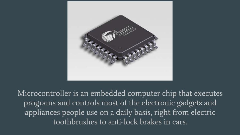
Microcontroller is an embedded computer chip that executes
programs and controls most of the electronic gadgets and
appliances people use on a daily basis, right from electric
toothbrushes to anti-lock brakes in cars.

1. Intro
I/O ControlEEPROM
Every
Microcontroller
Has….

Then what’s the difference between a Computer and a Microcontroller?
Well…..
Will you use a computer with 2.5Ghz Intel core I7, with 8GB RAM, 1TB
Hard disk, 2GB graphics card to make a techkriti game…?
No, right!
● Because its highly expensive.
● It is designed to be used for various purposes like word processing,
multimedia,gaming so on. In fact it has almost no limit to the
applications it can run.
● Its applications demand very high processing power.

On the other hand,Microcontroller is limited in its processing power.
Atmega328 has 8bit AVR CPU, 20MHz clock, 32kB Flash, 2kB RAM which is
considered to be more than sufficient… for many applications!
It is designed to be used in specific control applications like….
● Keyboard/ Mouse/ Calculators
● Water level Controllers/ Voting Machines
● Airbag System in Vehicles
● Basic GSM Mobiles
● Digital Washing Machines/ Microwave Oven

Would you believe that each one of you is using at least 20 microcontrollers in your house??!! Well, that’s a fact.

Now let’s start building something using a Microcontroller
Out of several available vendors like Atmel,
Intel, ARM, Cypress, etc. We will use
Atmel’s ATmega microcontrollers
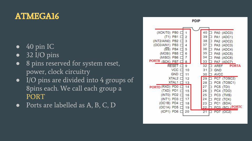
ATMEGA16
● 40 pin IC
● 32 I/O pins
● 8 pins reserved for system reset,
power, clock circuitry
● I/O pins are divided into 4 groups of
8pins each. We call each group a
PORT
● Ports are labelled as A, B, C, D

So, let's begin with the very basic question of how to
control these Input / Output pins ?
It is exactly for this purpose
I/O Registers are used….
The only way of interaction with external world is through
these I/O pins.

I/O Registers● I/O pins are controlled through special variables called “registers”
● Registers are special memory locations inside the μC with predefined
names and sizes. They act as a bridge between CPU & external I/O pins.
● Unlike normal memory, assigning a value to these registers in the
program changes the corresponding hardware configuration.
● And, these values can be altered multiple number of time at any point in
the program.
● There are 3 registers that control the I/O pins: DDR, PORT and PIN.
Each port has it’s own registers. Hence, DDRC, PORTC, PINC registers
for port C; DDRB, PORTB, PINB for port B and likewise
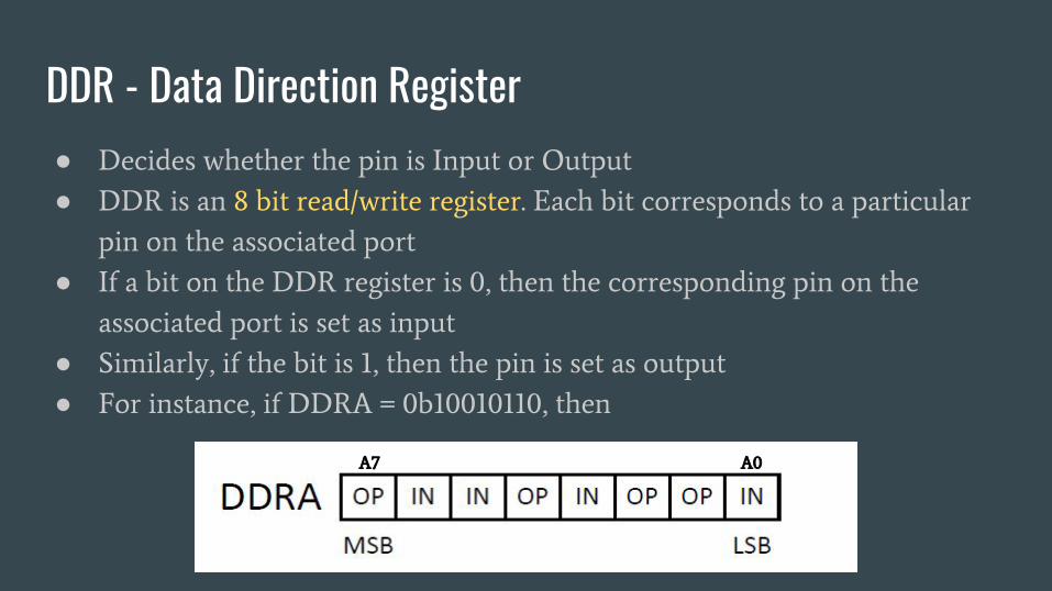
DDR - Data Direction Register● Decides whether the pin is Input or Output
● DDR is an 8 bit read/write register. Each bit corresponds to a particular
pin on the associated port
● If a bit on the DDR register is 0, then the corresponding pin on the
associated port is set as input
● Similarly, if the bit is 1, then the pin is set as output
● For instance, if DDRA = 0b10010110, then
A7 A0

PORT Register● PORT is also an 8 bit read/write register. The bits on the PORT register
correspond to the pins of the associated port in the same manner as in the
case of the DDR register.
● PORT is used to set the output value.
● If the pin is set as output, then a PORT value of 1 will set voltage at that
pin to 5V, and PORT value 0 sets the voltage to 0V.
● If the pin is configured as an input, PORT value serves the purpose of
pull up(if ‘1’) or leave the input as floating(if ‘0’).

PIN Register
● PIN is an 8-bit read-only register meaning it can only be read but cannot
be changed inside the program
● It contains the value of the actual voltage at a particular pin. 1, if the value
at the required pin is 5V and 0 for 0V.

Summary
PORTx.n=0 PORTx.n=1 PORTx.n=0 PORTx.n=1
Pin is set to be
input.Left floating
unless an external
voltage is applied
Avoid this
practice as the
operation gets
erratic.
Pin is set to be
input and
pulled-up.
If unconnected,
PINx.n is ‘1’
Pin is set to be
output with
value ‘0’.
PINx.n is equal
to PORTx.n
Pin is set to be
output with
value ‘1’.
PINx.n is equal
to PORTx.n
DDRx.n=0 DDRx.n=1

Circuit Level
Implementation of I/O
control….
Just to emphasize the
difference between normal
memory and I/O registers!
Is it really a bad idea to leave a MCU input pin floating….?
● Increases the error of operation due to
unknown state of input
● Drastically increases the power consumption
especially in CMOS based circuits due to
increased current
● Pulling up/ down with low value resistors is
also a bad practice as the current consumption
might be increased more than the rating value
which might result in unusual IC operation.
10k Ohm Resistors are typically used for pull
up/down purpose.
Yes!!!

Now that we got a basic idea of
how to control the I/O pins, let’s
get into programming our MCU….

● Atmega microcontrollers can be programmed
using either Assembly or C language
● Programs in C are more flexible and quicker
to develop.
● In comparison, programs in assembly often
have better performance, they run faster and
use less memory, resulting in lower cost
Programming
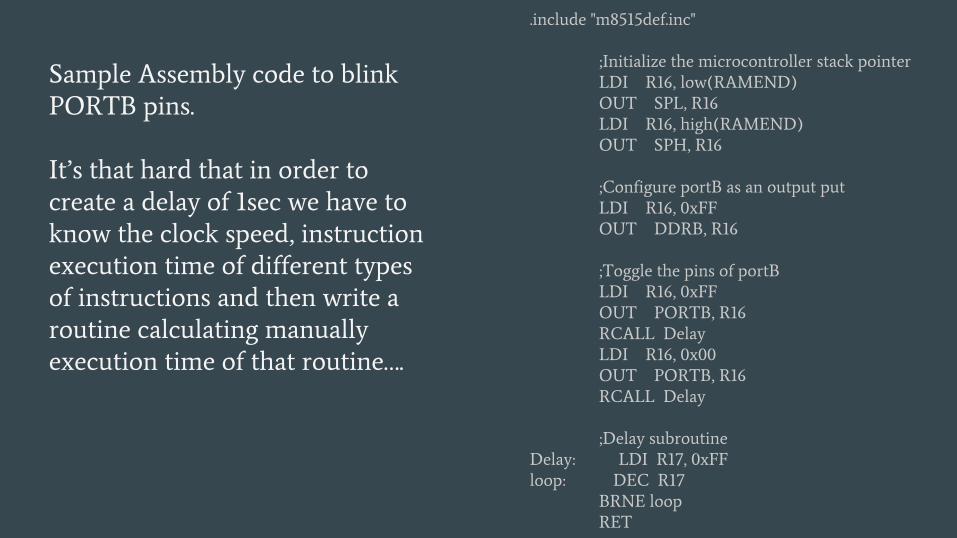
.include "m8515def.inc"
;Initialize the microcontroller stack pointer
LDI R16, low(RAMEND)
OUT SPL, R16
LDI R16, high(RAMEND)
OUT SPH, R16
;Configure portB as an output put
LDI R16, 0xFF
OUT DDRB, R16
;Toggle the pins of portB
LDI R16, 0xFF
OUT PORTB, R16
RCALL Delay
LDI R16, 0x00
OUT PORTB, R16
RCALL Delay
;Delay subroutine
Delay: LDI R17, 0xFF
loop: DEC R17
BRNE loop
RET
Sample Assembly code to blink
PORTB pins.
It’s that hard that in order to
create a delay of 1sec we have to
know the clock speed, instruction
execution time of different types
of instructions and then write a
routine calculating manually
execution time of that routine….
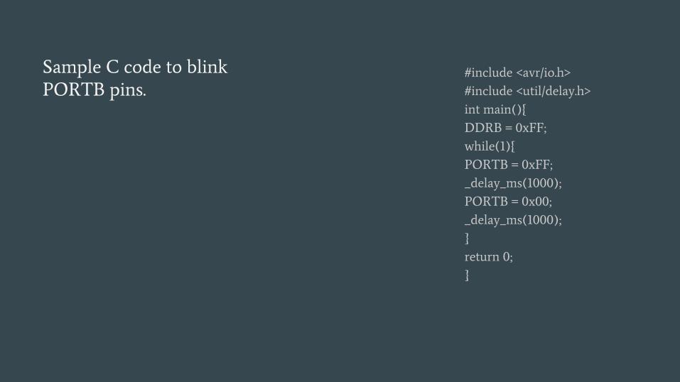
#include <avr/io.h>
#include <util/delay.h>
int main(){
DDRB = 0xFF;
while(1){
PORTB = 0xFF;
_delay_ms(1000);
PORTB = 0x00;
_delay_ms(1000);
}
return 0;
}
Sample C code to blink
PORTB pins.

Which Programming Language will you choose?
I’ll choose C

Useful
Libraries…..
They help us concentrate
more on code rather than
internal hardware
configuration of
microcontrollers
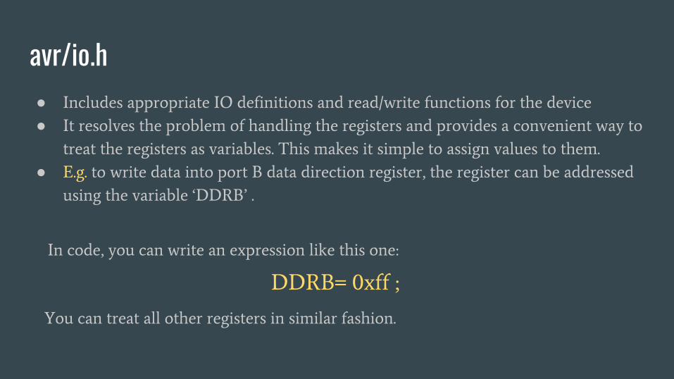
avr/io.h● Includes appropriate IO definitions and read/write functions for the device
● It resolves the problem of handling the registers and provides a convenient way to
treat the registers as variables. This makes it simple to assign values to them.
● E.g. to write data into port B data direction register, the register can be addressed
using the variable ‘DDRB’ .
DDRB= 0xff ;
In code, you can write an expression like this one:
You can treat all other registers in similar fashion.
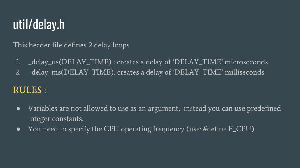
util/delay.hThis header file defines 2 delay loops.
1. _delay_us(DELAY_TIME) : creates a delay of ‘DELAY_TIME’ microseconds
2. _delay_ms(DELAY_TIME): creates a delay of ‘DELAY_TIME’ milliseconds
RULES :
● Variables are not allowed to use as an argument, instead you can use predefined
integer constants.
● You need to specify the CPU operating frequency (use: #define F_CPU).

int main()
{ #define F_CPU 1000000
int DELAY=0;
DELAY=29;
_delay_us(DELAY);
}
int main()
{ #define F_CPU 1000000
int DELAY=0;
for(DELAY=35;DELAY>=0;DELAY--)
{ _delay_us(DELAY); }
}
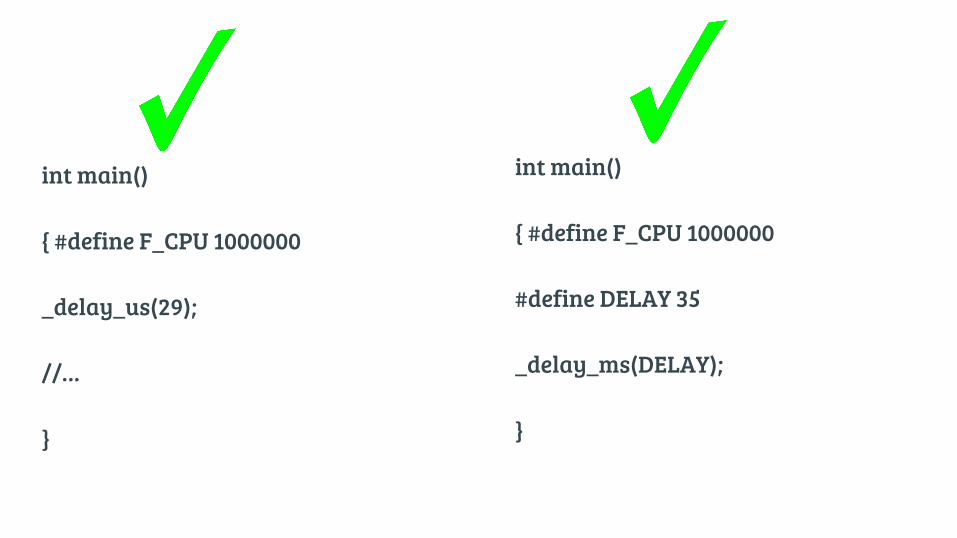
int main()
{ #define F_CPU 1000000
_delay_us(29);
//…
}
int main()
{ #define F_CPU 1000000
#define DELAY 35
_delay_ms(DELAY);
}

Miscellaneous
● string.h : defines some functions to make operations over strings. Like
comparing, joining two strings, copying two strings, moving one string to
some other location and few more.
● math.h : defines mathematical functions like sin(), cos(), tan(), exp() and
much more.
● stdlib.h : it include some standard library functions like exit(),
calloc(),malloc(),qsort() {qsort stands for quick sorting}, realloc() etc…,

Basic C operators that might come handy….Operator Symbol Operation Syntax Use
bitwise OR | 10100111 | 11000101 = 11100111PORTA = (PORTA |
0b00001010) ;
Set
bitwise AND & 10100111 & 11000101 =
10000101
PORTB = (PORTB &
0b00001010) ;
Clear,
Mask
bitwise NOT ~ ~10100110 = 01011001PORTB=~ 0b00001010 ;
Toggle all
bitwise XOR ^ 10100111 ^ 11000101 =
01100010
PORTB = (PORTB ^
0b00001010) ;
Toggle
specific
shift left
shift right
<<
>>
(0b00000001<<3)=0b00001000
(0b00001000>>3)=0b00000001
PORTB=PORTB ^ (1 << 2);
PORTB=PORTB ^ (1 >> i);
Display
motion

Okay, code is done….!
Now What…?
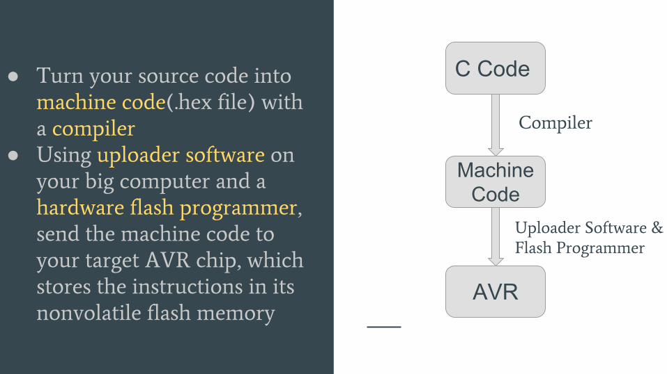
● Turn your source code into
machine code(.hex file) with
a compiler
● Using uploader software on
your big computer and a
hardware flash programmer,
send the machine code to
your target AVR chip, which
stores the instructions in its
nonvolatile flash memory
C Code
Machine Code
AVR
Compiler
Uploader Software &
Flash Programmer

Softwares Required
● Compiler : avr-gcc● Uploader Software : avrdude

Software DownloadWindows users have two options to download the software
1. Atmel Studio IDE (huge)
2. WinAVR (1/20 the file size and 9/10 of the functionality)
Link : https://sourceforge.net/projects/winavr/files/WinAVR/20100110/
Link : http://www.atmel.com/microsite/atmel-studio/
Note : During the installation, WinAVR will offer to change your PATH variable so that all of the binary files (importantly make, avrdude, and avr-gcc) are available without typing the full pathnames in. Be sure that you allow this.
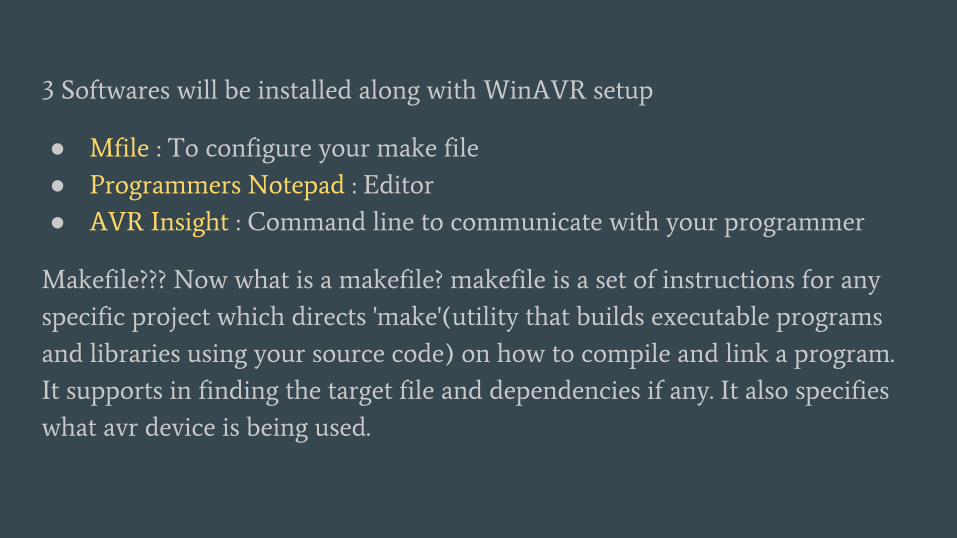
3 Softwares will be installed along with WinAVR setup
● Mfile : To configure your make file
● Programmers Notepad : Editor
● AVR Insight : Command line to communicate with your programmer
Makefile??? Now what is a makefile? makefile is a set of instructions for any
specific project which directs 'make'(utility that builds executable programs
and libraries using your source code) on how to compile and link a program.
It supports in finding the target file and dependencies if any. It also specifies
what avr device is being used.

Configuring ‘Make’ fileIn the MFile GUI that was installed along with WinAVR setup, make following
changes
● MCU
This is the type of AVR chip you’re using. In our case, we’re using an ATmega16,
so it reads atmega16.
● F_CPU
This definition tells the compiler what clock speed your chip is running at. If
you don’t have an external clock source, like a crystal, this is either 1,000,000
or 8,000,000 for the ATmega chips—one megahertz or eight megahertz. Getting
this right will matter for the timing of serial communication, and anything
else where timing is key like delay functions.

● BAUD
This is the baud rate that you’re going to use for computer-to-AVR serial
communications, and 9,600 baud is a good conservative default.
● MAIN
This entry is just the name of the program that you’re compiling and flashing
—the code that contains the main() routine.
● PROGRAMMER_TYPE
The type of programmer you are using
After making above changes, use Tools>Make All option in programmer’s notepad to create .hex file of your source code. Don’t forget to place your C code and make file in same directory
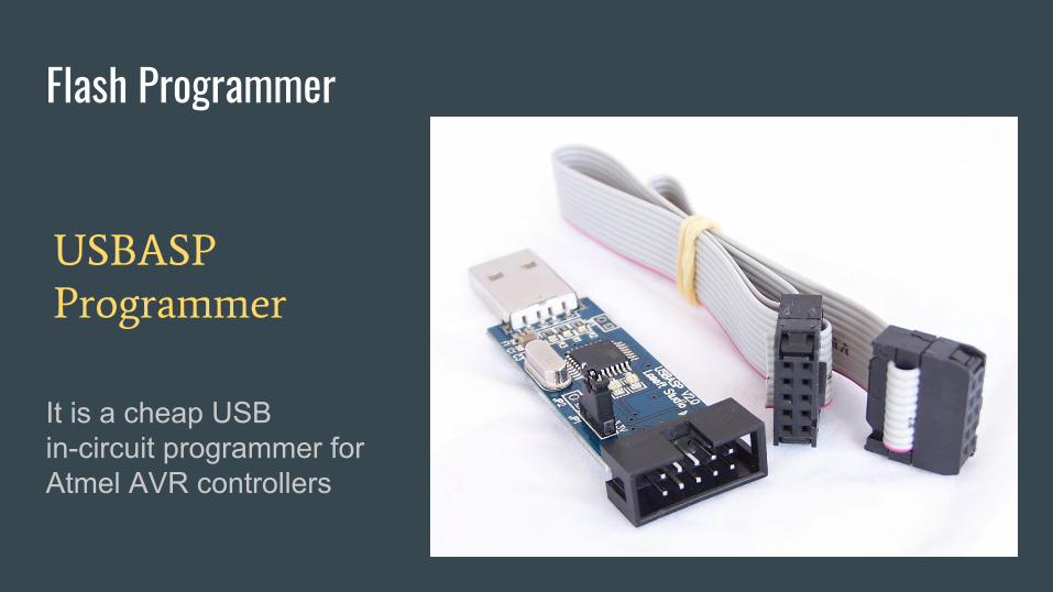
Flash Programmer
USBASP
Programmer
It is a cheap USB in-circuit programmer for Atmel AVR controllers
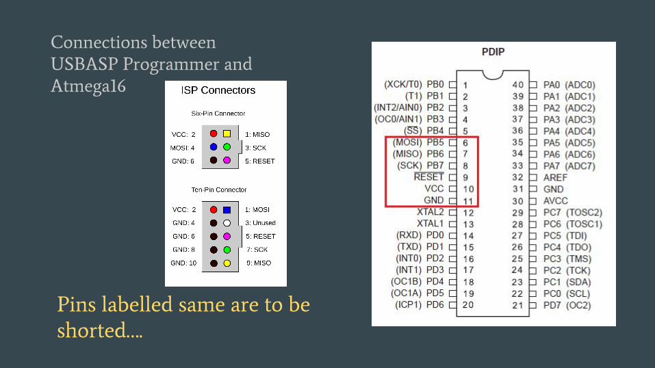
Connections between
USBASP Programmer and
Atmega16
Pins labelled same are to be
shorted….

● After making connections of programmer, open your windows command prompt
and using specific avrdude commands you can upload your program onto AVR
chip
Check various AVRDUDE commands here :
http://www.ladyada.net/learn/avr/avrdude.html
If you are feeling uncomfortable with terminal command executions you can also
download a avrdude GUI from here : https://github.com/elementzonline/USBASP
This GUI will also help you to make changes to FUSE bits(to use external clocks) in
more simple way

If you have problems with the driver for
usbasp programmer/ detection of usbasp
programmer install/update the driver for
usbasp
Check this for doing so :
https://netmaxtech.com/how-to-make/install-us
basp-driver-windows-8-and-windows

ReferencesLibraries : http://www.circuitstoday.com/avr-gcc-library-of-avr-studio
Change FUSE bits : Helps in configuring various clock sources and their frequencies
http://treehouseprojects.ca/fusebits/
Interrupts :
http://www.avr-tutorials.com/interrupts/The-AVR-8-Bits-Microcontrollers-External-Int
errupts
Programming Using USBASP :
https://elementztechblog.wordpress.com/2014/06/13/programming-atmega16-using-avr-
usbasp/