INTRODUCTION TO LINEAR STATIC ANALYSIS USING MSC.PATRAN...
19
INTRODUCTION TO LINEAR STATIC ANALYSIS USING MSC.PATRAN/NASTRAN Goal The goal of this exercise is to set-up a simple linear static analysis of a square plate using shell elements. The plate is fixed on two edges and subjected to a point force. Simulation results (displacements) are shown. Exercise outline Model setup Model definition Geometry Mesh Boundary conditions (BCs) Material properties Loadcase Analysis Results evaluation Model setup Create new working folder. Create new file, change its name and extension to *.db Double click to open the file in default program - Patran. In Patran choose new file choose previously created file
Transcript of INTRODUCTION TO LINEAR STATIC ANALYSIS USING MSC.PATRAN...

INTRODUCTION TO LINEAR STATIC ANALYSIS USING
MSC.PATRAN/NASTRAN
Goal
The goal of this exercise is to set-up a simple linear static analysis of a square plate using shell
elements. The plate is fixed on two edges and subjected to a point force. Simulation results
(displacements) are shown.
Exercise outline
Model setup
Model definition
Geometry
Mesh
Boundary conditions (BCs)
Material properties
Loadcase
Analysis
Results evaluation
Model setup
Create new working folder.
Create new file, change its name and extension to *.db
Double click to open the file in default program - Patran.
In Patran choose new file
choose previously created file
confirm creating new file message
choose model preferences
change default model units to millimeters
Model definition
Model geometry
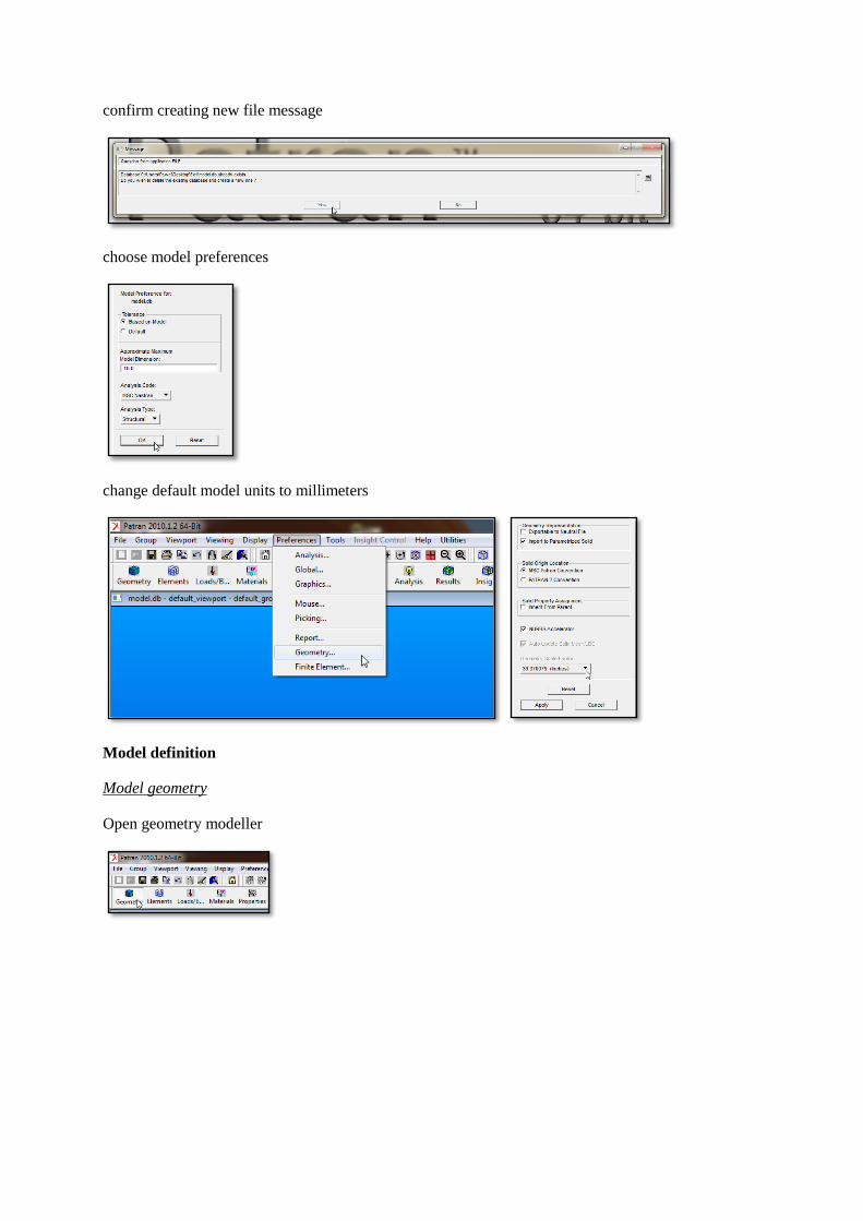
Open geometry modeller
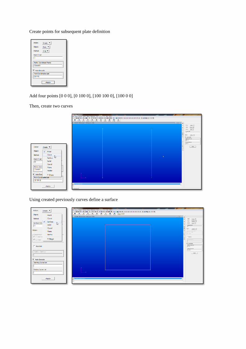
Create points for subsequent plate definition
Add four points [0 0 0], [0 100 0], [100 100 0], [100 0 0]
Then, create two curves
Using created previously curves define a surface

You can change display mode by using various options from the bar at the top of the screen
Lighting can be managed by through Light sources menu
Select all light sources and apply
Mesh definition
Once the geometry has been created, proceed to mesh definition

Use automatic ISO mesher to create unifrom mesh with element edge size of 10 mm
The model should now look like this
Boundary conditions
Open Loads/BCs menu

Define new boundary condition - fix nodes at two edges of the plate. Specify BC's name, ...
... constraints (DOFs), ...
... and application region

apply changes
The model should look like this

Prescribe a force at selected node
Change BC type to force
Specify desired force magnitude and apply

Select application region, apply
The model should now look like this
Material properties
Open material definition menu

Specify material's name
and its properties

Save changes by clicking apply
Open properties menu from the bar at the top of the screen, specify name
Select "Input properties", and choose alreade defined material by clicking material button

choose defined material
specify plate thickness
Specify application region

select all the elements and apply
Loadcase definition
Apply specified loads to create a loadcase. Open loadcase menu, select Action: Modify

Select default Loadcase
check if both previously defined boundary conditions are selected

Confirm by clicking apply
Analysis
proceed to analysis menu
switch analysis method to "analysis deck", this will create solver input file, but will not submit it to the
solver
Check it the solution type is set to static analysis and apply
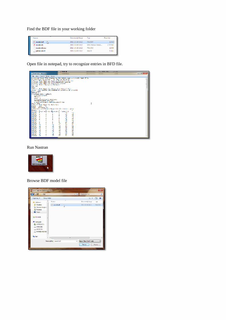
Find the BDF file in your working folder
Open file in notepad, try to recognize entries in BFD file.
Run Nastran
Browse BDF model file

Run the analysis
After Nastran finishes, check if *.xdb result file has been created
Result evaluation
In Analysis menu, find "Access Results" option
Select results file and apply
Go to Results menu

Check results you want to display
You can change display settings, e.g. turn off undeformed model configuration
and geometry in Plot/Erase menu

Simulation results should now look like this