Introduction to IBM S/390 FICON
62
Introduction to IBM S/390 FICON Ken Trowell, Marg Beal, Robert Beiderbeck, Trevor Biddle, Yusuke Ikeda, George Middleton International Technical Support Organization SG24-5176-00 http://www.redbooks.ibm.com
Transcript of Introduction to IBM S/390 FICON
Introduction to IBM S/390 FICON
Ken Trowell, Marg Beal, Robert Beiderbeck,Trevor Biddle, Yusuke Ikeda, George Middleton
International Technical Support Organization
SG24-5176-00
http://www.redbooks.ibm.com

International Technical Support Organization SG24-5176-00
Introduction to IBM S/390 FICON
October 1999

© Copyright International Business Machines Corporation 1999. All rights reserved.Note to U.S Government Users - Documentation related to restricted rights - Use, duplication or disclosure is subject to restrictionsset forth in GSA ADP Schedule Contract with IBM Corp.
First Edition (October 1999)
This edition applies to S/390 9672 Generation 5 and Generation 6 processors that will have LIC code 22 or higherinstalled and the 9032 Model 5 ESCON Directors that will have the FICON enablement feature installed.
Comments may be addressed to:IBM Corporation, International Technical Support OrganizationDept. HYJ Mail Station P099522 South RoadPoughkeepsie, NY 12601-5400
When you send information to IBM, you grant IBM a non-exclusive right to use or distribute the information in any wayit believes appropriate without incurring any obligation to you.
Before using this information and the product it supports, be sure to read the general information in Appendix A,“Special Notices” on page 37.
Take Note!
Contents
Preface . . . . . . . . . . . . . . . . . . . . . . . . . . . . . . . . . . . . . . . . . . . . . . . . . . . . . . .vThe Team That Wrote This Redbook . . . . . . . . . . . . . . . . . . . . . . . . . . . . . . . . . . . . vComments Welcome . . . . . . . . . . . . . . . . . . . . . . . . . . . . . . . . . . . . . . . . . . . . . . . . vi
Chapter 1. Introduction . . . . . . . . . . . . . . . . . . . . . . . . . . . . . . . . . . . . . . . . . .11.1 Today’s Environment . . . . . . . . . . . . . . . . . . . . . . . . . . . . . . . . . . . . . . . . .1
Chapter 2. S/390 FICON Overview . . . . . . . . . . . . . . . . . . . . . . . . . . . . . . . . .32.1 S/390 Evolution. . . . . . . . . . . . . . . . . . . . . . . . . . . . . . . . . . . . . . . . . . . . . .32.2 S/390 Evolution continued . . . . . . . . . . . . . . . . . . . . . . . . . . . . . . . . . . . . .42.3 S/390 I/O Futures . . . . . . . . . . . . . . . . . . . . . . . . . . . . . . . . . . . . . . . . . . . .52.4 S/390 I/O Futures continued . . . . . . . . . . . . . . . . . . . . . . . . . . . . . . . . . . . .62.5 Customer Requirements . . . . . . . . . . . . . . . . . . . . . . . . . . . . . . . . . . . . . . .72.6 Potential S/390 I/O Solutions . . . . . . . . . . . . . . . . . . . . . . . . . . . . . . . . . . .82.7 S/390 Fiber Connection . . . . . . . . . . . . . . . . . . . . . . . . . . . . . . . . . . . . . . .92.8 S/390 Fiber Channel Support . . . . . . . . . . . . . . . . . . . . . . . . . . . . . . . . . .102.9 ESCON to FICON Migration . . . . . . . . . . . . . . . . . . . . . . . . . . . . . . . . . . .112.10 ESCON to FICON (FCV) Aggregation . . . . . . . . . . . . . . . . . . . . . . . . . . .122.11 Fiber Connection Attachment - FICON Bridge . . . . . . . . . . . . . . . . . . . . .132.12 FICON Native Configuration . . . . . . . . . . . . . . . . . . . . . . . . . . . . . . . . . .142.13 Fiber Connection Attachment - FICON Direct . . . . . . . . . . . . . . . . . . . . .152.14 Fiber Connection Attachment - FICON Switch. . . . . . . . . . . . . . . . . . . . .162.15 Sample Implementation. . . . . . . . . . . . . . . . . . . . . . . . . . . . . . . . . . . . . .172.16 Overview Summary . . . . . . . . . . . . . . . . . . . . . . . . . . . . . . . . . . . . . . . . .18
Chapter 3. Architecture Overview . . . . . . . . . . . . . . . . . . . . . . . . . . . . . . . .193.1 Requirements for a New Architecture . . . . . . . . . . . . . . . . . . . . . . . . . . . .193.2 FICON Architecture. . . . . . . . . . . . . . . . . . . . . . . . . . . . . . . . . . . . . . . . . .203.3 ESCON to FICON (FCV) Comparisons . . . . . . . . . . . . . . . . . . . . . . . . . . .223.4 ESCON Channel Command Processing . . . . . . . . . . . . . . . . . . . . . . . . . .23
Chapter 4. FICON Cabling . . . . . . . . . . . . . . . . . . . . . . . . . . . . . . . . . . . . . .254.1 FICON Fiber Cabling. . . . . . . . . . . . . . . . . . . . . . . . . . . . . . . . . . . . . . . . .254.2 Cabling Requirements. . . . . . . . . . . . . . . . . . . . . . . . . . . . . . . . . . . . . . . .264.3 FICON FCV Configuration. . . . . . . . . . . . . . . . . . . . . . . . . . . . . . . . . . . . .274.4 Fiber Cabling Connect . . . . . . . . . . . . . . . . . . . . . . . . . . . . . . . . . . . . . . .284.5 Fiber Cabling Types . . . . . . . . . . . . . . . . . . . . . . . . . . . . . . . . . . . . . . . . .294.6 Fiber Cable Re-use . . . . . . . . . . . . . . . . . . . . . . . . . . . . . . . . . . . . . . . . . .304.7 Fiber Mode Conditioner Patch Cables . . . . . . . . . . . . . . . . . . . . . . . . . . . .314.8 Fiber Cabling Remote Sites Benefits . . . . . . . . . . . . . . . . . . . . . . . . . . . . .324.9 FICON Remote Site Configuration . . . . . . . . . . . . . . . . . . . . . . . . . . . . . .334.10 S/390 Fiber Cabling Requirements . . . . . . . . . . . . . . . . . . . . . . . . . . . . .34
Chapter 5. ESCON to FICON Migration Tips . . . . . . . . . . . . . . . . . . . . . . . .355.1 Ahead of Migration . . . . . . . . . . . . . . . . . . . . . . . . . . . . . . . . . . . . . . . . . .35
Appendix A. Special Notices . . . . . . . . . . . . . . . . . . . . . . . . . . . . . . . . . . . . . . 37
Appendix B. Related Publications . . . . . . . . . . . . . . . . . . . . . . . . . . . . . . . . . . 39B.1 International Technical Support Organization Publications. . . . . . . . . . . . . . . 39B.2 Redbooks on CD-ROMs . . . . . . . . . . . . . . . . . . . . . . . . . . . . . . . . . . . . . . . . . 39B.3 Other Publications. . . . . . . . . . . . . . . . . . . . . . . . . . . . . . . . . . . . . . . . . . . . . . 39
© Copyright IBM Corp. 1999 iii

How to Get ITSO Redbooks . . . . . . . . . . . . . . . . . . . . . . . . . . . . . . . . . . . . . 41IBM Redbook Fax Order Form . . . . . . . . . . . . . . . . . . . . . . . . . . . . . . . . . . . . . . . .42
Glossary . . . . . . . . . . . . . . . . . . . . . . . . . . . . . . . . . . . . . . . . . . . . . . . . . . . . 43
List of Abbreviations . . . . . . . . . . . . . . . . . . . . . . . . . . . . . . . . . . . . . . . . . . 49
Index . . . . . . . . . . . . . . . . . . . . . . . . . . . . . . . . . . . . . . . . . . . . . . . . . . . . . . . 51
ITSO Redbook Evaluation . . . . . . . . . . . . . . . . . . . . . . . . . . . . . . . . . . . . . . 53
iv Introduction to IBM S/390 FICON

Preface
This redbook gives a broad understanding of the concepts and capabilities of thenew S/390 FICON architecture and channels.
The information in this redbook is presented to provide some awareness of therequirements of FICON (FCV) configurations to facilitate the migration to FICONchannels prior to the channels being installed.
The Team That Wrote This Redbook
This redbook was produced by a team of specialists from around the world aspart of the IBM Poughkeepsie FICON project working at the InternationalTechnical Support Organization Poughkeepsie Center.
Ken Trowell is a S/390 Systems Specialist at the International Technical SupportOrganization, Poughkeepsie Center. He writes extensively and presents at IBMworkshops worldwide on all areas of S/390 Processors, Channels, ChannelTopology, and S/390 Architecture. Before joining the ITSO 3 years ago, Kenworked in a number of IBM countries during his extensive career in IBM,providing system support and consulting activities in the S/390 area.
Marg Beal was a Consulting Services Specialist in IBM Australia. She has 24years of experience supporting MVS and OS/390, and her areas of expertiseinclude ESCON configuration, as well as recovery and availability of complexMVS configurations. She has written extensively on MVS recovery facilities andtaught many customer courses in operational recovery techniques.
Robert Beiderbeck is a Large Systems Hardware Specialist, in IBM Germany.He has 11 years of experience with IBM, including 3 years at the HardwareSupport Center. His areas of expertise include supporting Parallel Sysplex inlarge ESCON environments. Robert is responsible for configuration changes andavailability management.
Trevor Biddle is an IT Specialist in the UK. He has 22 years of experience in theareas of Operations, Systems Programming, and IT Consultancy. His areas ofexpertise include the implementation of S/390 products and solutions. He hasworked on many leading-edge projects in the GRS, Sysplex, Parallel Sysplex andDFSMS product areas. He has written extensively on large systems topics suchas RMF Performance Reporting, DFSMS Implementation, DFSMS Optimizer andVSAM/RLS Recovery.
Yusuke Ikeda is an IT Specialist in IBM Japan. He has 12 years of experiencewith IBM. His areas of expertise include S/390 processor and ESCONconfiguration. He supports the field in S/390 configuration and performancemanagement. He has written extensively on S/390 hardware topics and taughtIBM classes in his country.
George Middleton is a Marketing Support Representative at the WashingtonSystems Center (WSC) in the USA. George has 33 years of experience with IBM,including 18 at the WSC, and 12 as a Systems Engineer in the field. Today, hisprimary expertise is ESCON and FICON connectivity, where his main emphasis issupporting the field in the implementation of ESCON Directors, and
© Copyright IBM Corp. 1999 v

ESCON/FICON configurations. In this capacity, George was also the ¨owner´ ofthe ESCON SAPR Guide.
Thanks to the following people for their invaluable contribution to this project:
Robert DuganS/390 Systems ArchitectureIBM Poughkeepsie
David AndersonS/390 PlanningIBM Poughkeepsie
Allan MerittS/390 System DesignIBM Poughkeepsie
Lou RicciS/390 Connectivity SolutionsIBM Poughkeepsie
Joan KellyS/390 Performance MeasurementsIBM Poughkeepsie
Harry YudenfriendOS/390 IOS DevelopmentIBM Poughkeepsie
Marten HalmaS/390 Technical Programs: I/O and StorageIBM Poughkeepsie
Comments Welcome
Your comments are important to us!
We want our redbooks to be as helpful as possible. Please send us yourcomments about this or other redbooks in one of the following ways:
• Fax the evaluation form found in “ITSO Redbook Evaluation” on page 53 to thefax number shown on the form.
• Use the online evaluation form found at http://www.redbooks.ibm.com/
• Send your comments in an internet note to [email protected]
vi Introduction to IBM S/390 FICON
Chapter 1. Introduction
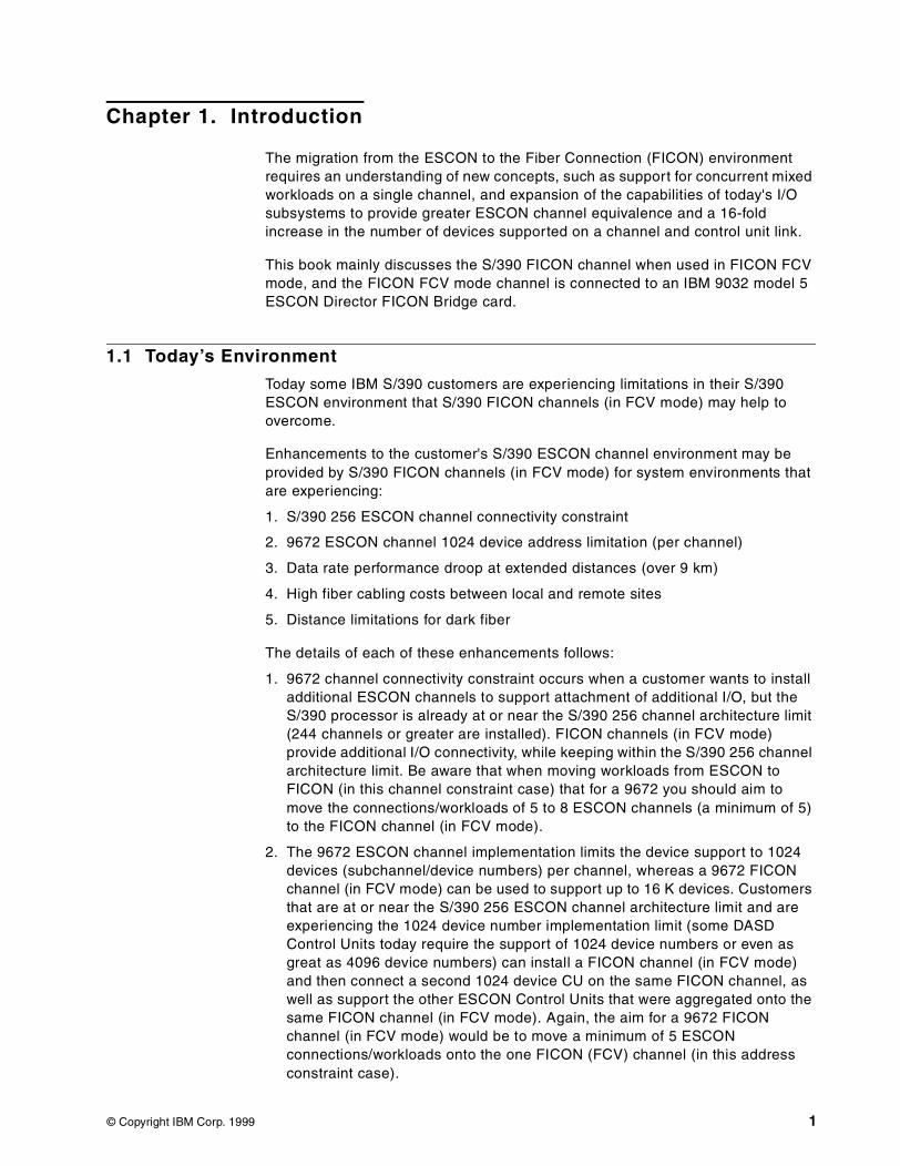
The migration from the ESCON to the Fiber Connection (FICON) environmentrequires an understanding of new concepts, such as support for concurrent mixedworkloads on a single channel, and expansion of the capabilities of today's I/Osubsystems to provide greater ESCON channel equivalence and a 16-foldincrease in the number of devices supported on a channel and control unit link.
This book mainly discusses the S/390 FICON channel when used in FICON FCVmode, and the FICON FCV mode channel is connected to an IBM 9032 model 5ESCON Director FICON Bridge card.
1.1 Today’s Environment
Today some IBM S/390 customers are experiencing limitations in their S/390ESCON environment that S/390 FICON channels (in FCV mode) may help toovercome.
Enhancements to the customer's S/390 ESCON channel environment may beprovided by S/390 FICON channels (in FCV mode) for system environments thatare experiencing:
1. S/390 256 ESCON channel connectivity constraint
2. 9672 ESCON channel 1024 device address limitation (per channel)
3. Data rate performance droop at extended distances (over 9 km)
4. High fiber cabling costs between local and remote sites
5. Distance limitations for dark fiber
The details of each of these enhancements follows:
1. 9672 channel connectivity constraint occurs when a customer wants to installadditional ESCON channels to support attachment of additional I/O, but theS/390 processor is already at or near the S/390 256 channel architecture limit(244 channels or greater are installed). FICON channels (in FCV mode)provide additional I/O connectivity, while keeping within the S/390 256 channelarchitecture limit. Be aware that when moving workloads from ESCON toFICON (in this channel constraint case) that for a 9672 you should aim tomove the connections/workloads of 5 to 8 ESCON channels (a minimum of 5)to the FICON channel (in FCV mode).
2. The 9672 ESCON channel implementation limits the device support to 1024devices (subchannel/device numbers) per channel, whereas a 9672 FICONchannel (in FCV mode) can be used to support up to 16 K devices. Customersthat are at or near the S/390 256 ESCON channel architecture limit and areexperiencing the 1024 device number implementation limit (some DASDControl Units today require the support of 1024 device numbers or even asgreat as 4096 device numbers) can install a FICON channel (in FCV mode)and then connect a second 1024 device CU on the same FICON channel, aswell as support the other ESCON Control Units that were aggregated onto thesame FICON channel (in FCV mode). Again, the aim for a 9672 FICONchannel (in FCV mode) would be to move a minimum of 5 ESCONconnections/workloads onto the one FICON (FCV) channel (in this addressconstraint case).
© Copyright IBM Corp. 1999 1

3. As the distance between an ESCON channel to an ESCON-attached CUincreases, the performance decreases (reduced data transfer rate) up to adistance of 9 km. At the 9 km point the performance decreases more rapidly.This point of sudden rapid decrease in performance is called the distance datarate droop point. For FICON channel links the distance where this data ratedroop point occurs is not until 100 km. This allows the customer to get thebenefit of an extended distance from a FICON channel (in FCV mode) withouthaving the same performance impact as seen on the ESCON channels afterthe 9 km distance. Allowable device connectivity distances must still beconsidered on the ESCON links.
4. Multiple ESCON channel fibers between two extended distance sites can bevery expensive. With the use of FICON channels (in FCV mode) between twosites we would expect the customer to get up to an 8-to-1 reduction in thenumber of fibers required to connect the 2 sites. This in most cases will benefitthe customer in a reduction of the overall cost of the fiber infrastructure.
5. Some customers prefer the use of dark fiber with no retransmission of the fibersignal. Using ESCON LED channels dark fiber distances can only be 3 km,while using FICON single mode 9 micron fiber, the dark fiber distance can beextended to 10 km, or even 20 km with an IBM approved RPQ.
The S/390 FICON channel (in FCV mode) provides some appreciableenhancements to the S/390 ESCON channel implementation. S/390 FICONchannels (in FCV mode) supplement the S/390 ESCON channels, providingconnectivity to additional ESCON interface Control Units. ESCON and FICON(FCV) connectivity coexists to ESCON Control Units.
Under some circumstances, where the 9672 S/390 processor will support theinstallation of additional ESCON channels, the additional ESCON channels mayprovide an adequate solution to the customer's ESCON environmentrequirements for the cases described in scenarios 1 and 2.
2 Introduction to IBM S/390 FICON
Chapter 2. S/390 FICON Overview
This chapter provides an overview of the new System/390 Fiber Connection(FICON) channel. FICON provides the key to allowing S/390 I/O subsystems tokeep pace with the rapid growth of S/390 processors and their applicationworkloads.
This chapter describes the imbalance in the growth of S/390 I/O when comparedwith the growth in CPU and storage, for example, and the customer applicationrequirements that led to the S/390 FICON solution.
2.1 S/390 Evolution
The System/390 hardware and software components have been changedsignificantly since the introduction of the first System/360 system in 1964.
The growth in some areas has been more explosive than others, and in terms ofoptimum configuration, it is important that all system components provide abalanced system as new technologies become available.
The ESCON channel architecture introduced in September 1990 provided manybenefits, such as improved performance, increased distance capability, switchingtopology, and so on. One of the implementation benefits was that there were noapplication software changes required, but the channel communication protocolswere constrained because of limits on the technology and the degree of allowableevolution (risk) with the chosen implementation.
Overview -S/390 Evolution
BackgroundEvolution of S/390
Contrast growth of I/O capability to that of CPU, storage andDASDNeed for balanced system
ESCON provided significant benefitsPerformanceDistanceSwitchingConnectivityTopologyEase of implementation
© Copyright IBM Corporation, 1998 and 1999
Chapter 2. S/390 FICON Overview 3
2.2 S/390 Evolution continued
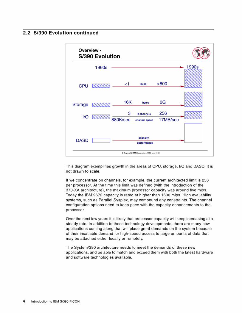
This diagram exemplifies growth in the areas of CPU, storage, I/O and DASD. It isnot drawn to scale.
If we concentrate on channels, for example, the current architected limit is 256per processor. At the time this limit was defined (with the introduction of the370-XA architecture), the maximum processor capacity was around five mips.Today the IBM 9672 capacity is rated at higher than 1600 mips. High availabilitysystems, such as Parallel Sysplex, may compound any constraints. The channelconfiguration options need to keep pace with the capacity enhancements to theprocessor.
Over the next few years it is likely that processor capacity will keep increasing at asteady rate. In addition to these technology developments, there are many newapplications coming along that will place great demands on the system becauseof their insatiable demand for high-speed access to large amounts of data thatmay be attached either locally or remotely.
The System/390 architecture needs to meet the demands of these newapplications, and be able to match and exceed them with both the latest hardwareand software technologies available.
Overview -S/390 Evolution
capacityDASD
CPU
Storage
I/O
mips
bytes
# channels
1960s 1990s
<1 >800
16K 2G
3 256
880K/sec 17MB/secchannel speed
performance
© Copyright IBM Corporation, 1998 and 1999
4 Introduction to IBM S/390 FICON
2.3 S/390 I/O Futures
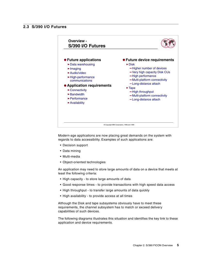
Modern-age applications are now placing great demands on the system withregards to data accessibility. Examples of such applications are:
• Decision support
• Data mining
• Multi-media
• Object-oriented technologies
An application may need to store large amounts of data on a device that meets atleast the following criteria:
• High capacity - to store large amounts of data
• Good response times - to provide transactions with high speed data access
• High throughput - to transfer large amounts of data quickly
• High availability - to provide access at all times
Although the Disk and tape subsystems obviously have to meet theserequirements, the channel subsystem has to match or exceed deliverycapabilities of such devices.
The following diagrams illustrates this situation and identifies the key link to theseapplication and device requirements.
Future applicationsData warehousingImagingAudio/videoHigh-performancecommunications
Application requirementsConnectivityBandwidthPerformanceAvailability
Overview -S/390 I/O Futures
Future device requirementsDisk
Higher number of devicesVery high capacity Disk CUsHigh performanceMulti-platform connectivityLong-distance attach
TapeHigh throughputMulti-platform connectivityLong-distance attach
© Copyright IBM Corporation, 1998 and 1999
Chapter 2. S/390 FICON Overview 5
2.4 S/390 I/O Futures continued
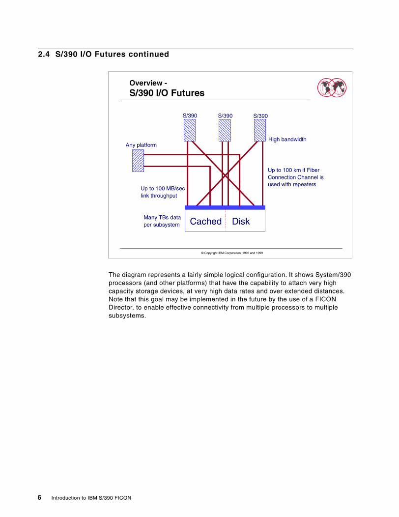
The diagram represents a fairly simple logical configuration. It shows System/390processors (and other platforms) that have the capability to attach very highcapacity storage devices, at very high data rates and over extended distances.Note that this goal may be implemented in the future by the use of a FICONDirector, to enable effective connectivity from multiple processors to multiplesubsystems.
Overview -S/390 I/O Futures
Up to 100 km if FiberConnection Channel isused with repeaters
Many TBs dataper subsystem Cached Disk
S/390 S/390 S/390
Any platformHigh bandwidth
Up to 100 MB/seclink throughput
© Copyright IBM Corporation, 1998 and 1999
6 Introduction to IBM S/390 FICON
2.5 Customer Requirements
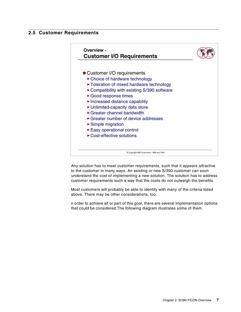
Any solution has to meet customer requirements, such that it appears attractiveto the customer in many ways. An existing or new S/390 customer can soonunderstand the cost of implementing a new solution. The solution has to addresscustomer requirements such a way that the costs do not outweigh the benefits.
Most customers will probably be able to identify with many of the criteria listedabove. There may be other considerations, too.
n order to achieve all or part of this goal, there are several implementation optionsthat could be considered.The following diagram illustrates some of them.
Overview -Customer I/O Requirements
Customer I/O requirementsChoice of hardware technologyToleration of mixed hardware technologyCompatibility with existing S/390 softwareGood response timesIncreased distance capabilityUnlimited-capacity data storeGreater channel bandwidthGreater number of device addressesSimple migrationEasy operational controlCost-effective solutions
© Copyright IBM Corporation, 1998 and 1999
Chapter 2. S/390 FICON Overview 7
2.6 Potential S/390 I/O Solutions
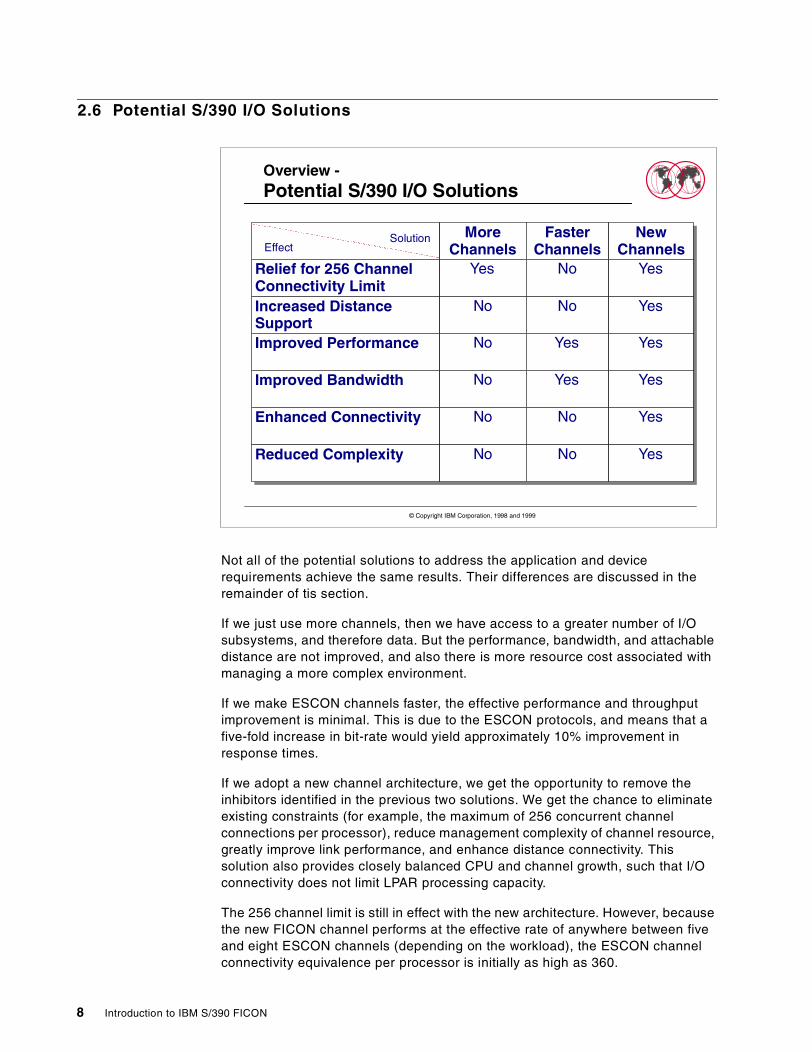
Not all of the potential solutions to address the application and devicerequirements achieve the same results. Their differences are discussed in theremainder of tis section.
If we just use more channels, then we have access to a greater number of I/Osubsystems, and therefore data. But the performance, bandwidth, and attachabledistance are not improved, and also there is more resource cost associated withmanaging a more complex environment.
If we make ESCON channels faster, the effective performance and throughputimprovement is minimal. This is due to the ESCON protocols, and means that afive-fold increase in bit-rate would yield approximately 10% improvement inresponse times.
If we adopt a new channel architecture, we get the opportunity to remove theinhibitors identified in the previous two solutions. We get the chance to eliminateexisting constraints (for example, the maximum of 256 concurrent channelconnections per processor), reduce management complexity of channel resource,greatly improve link performance, and enhance distance connectivity. Thissolution also provides closely balanced CPU and channel growth, such that I/Oconnectivity does not limit LPAR processing capacity.
The 256 channel limit is still in effect with the new architecture. However, becausethe new FICON channel performs at the effective rate of anywhere between fiveand eight ESCON channels (depending on the workload), the ESCON channelconnectivity equivalence per processor is initially as high as 360.
Overview -Potential S/390 I/O Solutions
MoreChannels
FasterChannels
NewChannels
Relief for 256 ChannelConnectivity Limit
Yes No Yes
Increased DistanceSupport
No No Yes
Improved Performance No Yes Yes
Improved Bandwidth No Yes Yes
Enhanced Connectivity No No Yes
Reduced Complexity No No Yes
EffectSolution
© Copyright IBM Corporation, 1998 and 1999
8 Introduction to IBM S/390 FICON
2.7 S/390 Fiber Connection
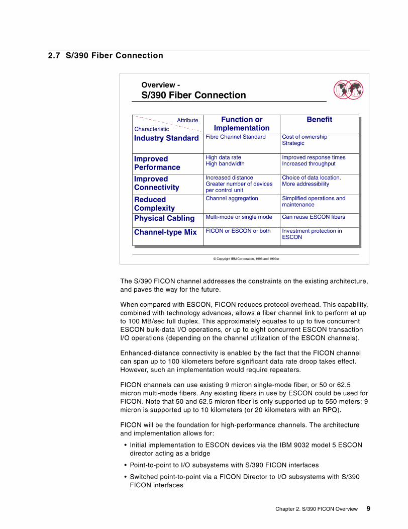
The S/390 FICON channel addresses the constraints on the existing architecture,and paves the way for the future.
When compared with ESCON, FICON reduces protocol overhead. This capability,combined with technology advances, allows a fiber channel link to perform at upto 100 MB/sec full duplex. This approximately equates to up to five concurrentESCON bulk-data I/O operations, or up to eight concurrent ESCON transactionI/O operations (depending on the channel utilization of the ESCON channels).
Enhanced-distance connectivity is enabled by the fact that the FICON channelcan span up to 100 kilometers before significant data rate droop takes effect.However, such an implementation would require repeaters.
FICON channels can use existing 9 micron single-mode fiber, or 50 or 62.5micron multi-mode fibers. Any existing fibers in use by ESCON could be used forFICON. Note that 50 and 62.5 micron fiber is only supported up to 550 meters; 9micron is supported up to 10 kilometers (or 20 kilometers with an RPQ).
FICON will be the foundation for high-performance channels. The architectureand implementation allows for:
• Initial implementation to ESCON devices via the IBM 9032 model 5 ESCONdirector acting as a bridge
• Point-to-point to I/O subsystems with S/390 FICON interfaces
• Switched point-to-point via a FICON Director to I/O subsystems with S/390FICON interfaces
Overview -S/390 Fiber Connection
Function orImplementation
Benefit
Industry Standard Fibre Channel Standard Cost of ownershipStrategic
ImprovedPerformance
High data rateHigh bandwidth
Improved response timesIncreased throughput
ImprovedConnectivity
Increased distanceGreater number of devicesper control unit
Choice of data location.More addressibility
ReducedComplexity
Channel aggregation Simplified operations andmaintenance
Physical Cabling Multi-mode or single mode Can reuse ESCON fibers
Channel-type Mix FICON or ESCON or both Investment protection inESCON
Characteristic
Attribute
© Copyright IBM Corporation, 1998 and 1999er
Chapter 2. S/390 FICON Overview 9
S/390 FICON supplements ESCON. It is not intended to be a replacement for it.Existing investment in ESCON can co-exist with FICON.
The rest of this section defines the prerequisites for a S/390 FICONimplementation. The following table shows required specifications for variouscomponents.
2.8 S/390 Fiber Channel Support
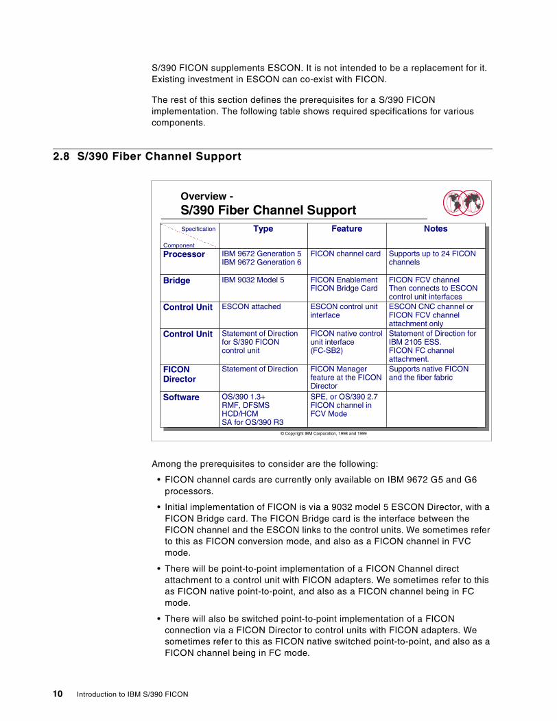
Among the prerequisites to consider are the following:
• FICON channel cards are currently only available on IBM 9672 G5 and G6processors.
• Initial implementation of FICON is via a 9032 model 5 ESCON Director, with aFICON Bridge card. The FICON Bridge card is the interface between theFICON channel and the ESCON links to the control units. We sometimes referto this as FICON conversion mode, and also as a FICON channel in FVCmode.
• There will be point-to-point implementation of a FICON Channel directattachment to a control unit with FICON adapters. We sometimes refer to thisas FICON native point-to-point, and also as a FICON channel being in FCmode.
• There will also be switched point-to-point implementation of a FICONconnection via a FICON Director to control units with FICON adapters. Wesometimes refer to this as FICON native switched point-to-point, and also as aFICON channel being in FC mode.
Overview -S/390 Fiber Channel Support
Type Feature Notes
Processor IBM 9672 Generation 5IBM 9672 Generation 6
FICON channel card Supports up to 24 FICONchannels
Bridge IBM 9032 Model 5 FICON EnablementFICON Bridge Card
FICON FCV channelThen connects to ESCONcontrol unit interfaces
Control Unit ESCON attached ESCON control unitinterface
ESCON CNC channel orFICON FCV channelattachment only
Control Unit Statement of Directionfor S/390 FICONcontrol unit
FICON native controlunit interface(FC-SB2)
Statement of Direction forIBM 2105 ESS.FICON FC channelattachment.
FICONDirector
Statement of Direction FICON Managerfeature at the FICONDirector
Supports native FICONand the fiber fabric
Software OS/390 1.3+RMF, DFSMSHCD/HCMSA for OS/390 R3
SPE, or OS/390 2.7FICON channel inFCV Mode
Component
Specification
© Copyright IBM Corporation, 1998 and 1999
10 Introduction to IBM S/390 FICON
There are software changes in OS/390 1.3 and later releases to support theFICON channels and exploit the performance enhancements of FICON. Alsothere are changes to access methods in DFSMS to exploit that support. SystemAutomation for OS/390, HCD and HCM have been updated to support the newchannel, and in the case of HCM provide migration facilities to the FICON Bridgeport. Changes have also been made to RMF to show the new measurementsassociated with the FICON channel.
2.9 ESCON to FICON Migration
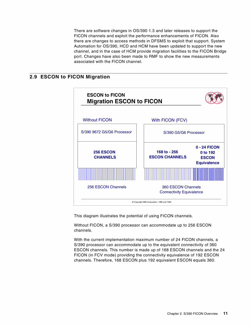
This diagram illustrates the potential of using FICON channels.
Without FICON, a S/390 processor can accommodate up to 256 ESCONchannels.
With the current implementation maximum number of 24 FICON channels, aS/390 processor can accommodate up to the equivalent connectivity of 360ESCON channels. This number is made up of 168 ESCON channels and the 24FICON (in FCV mode) providing the connectivity equivalence of 192 ESCONchannels. Therefore, 168 ESCON plus 192 equivalent ESCON equals 360.
ESCON to FICONMigration ESCON to FICON
Without FICON With FICON (FCV)
S/390 9672 G5/G6 Processor S/390 G5/G6 Processor
168 to - 256ESCON CHANNELS
0 - 24 FICON0 to 192ESCON
Equivalence
256 ESCONCHANNELS
256 ESCON Channels 360 ESCON ChannelsConnectivity Equivalence
© Copyright IBM Corporation, 1998 and 1999
Chapter 2. S/390 FICON Overview 11
2.10 ESCON to FICON (FCV) Aggregation
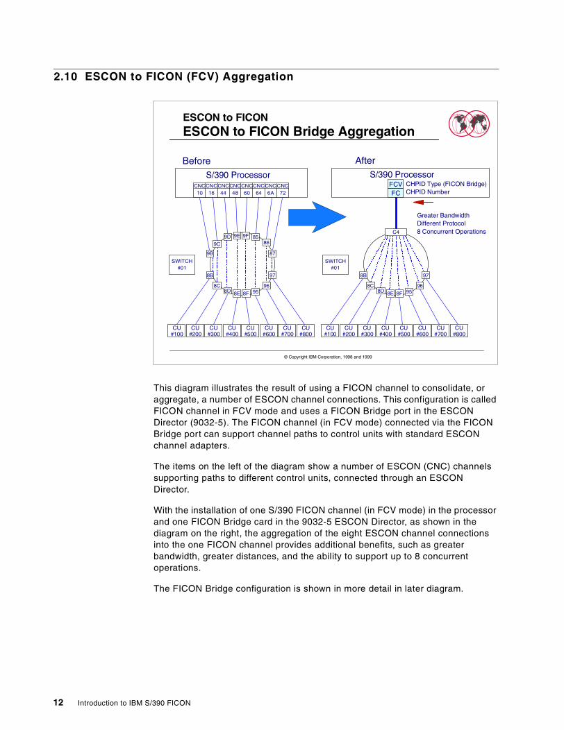
This diagram illustrates the result of using a FICON channel to consolidate, oraggregate, a number of ESCON channel connections. This configuration is calledFICON channel in FCV mode and uses a FICON Bridge port in the ESCONDirector (9032-5). The FICON channel (in FCV mode) connected via the FICONBridge port can support channel paths to control units with standard ESCONchannel adapters.
The items on the left of the diagram show a number of ESCON (CNC) channelssupporting paths to different control units, connected through an ESCONDirector.
With the installation of one S/390 FICON channel (in FCV mode) in the processorand one FICON Bridge card in the 9032-5 ESCON Director, as shown in thediagram on the right, the aggregation of the eight ESCON channel connectionsinto the one FICON channel provides additional benefits, such as greaterbandwidth, greater distances, and the ability to support up to 8 concurrentoperations.
The FICON Bridge configuration is shown in more detail in later diagram.
ESCON to FICONESCON to FICON Bridge Aggregation
Before AfterS/390 Processor
FCVFC
Greater BandwidthDifferent Protocol8 Concurrent Operations
CNC10
CNCCNCCNCCNCCNC16 44 48 60 64
CNCCNC6A 72
S/390 Processor
SWITCH#01
CU#100
CU#200
CU#500
CU#600
CU#300
CU#400
CU#700
CU#800
9D 9E
958F
9F
8D 8E
9B
8B
9C
8C
8586
87
96
97
SWITCH#01
CU#100
CU#200
CU#500
CU#600
CU#300
CU#400
CU#700
CU#800
958F8D 8E
8B
8C 96
97
C4
CHPID Type (FICON Bridge)CHPID Number
© Copyright IBM Corporation, 1998 and 1999
12 Introduction to IBM S/390 FICON
2.11 Fiber Connection Attachment - FICON Bridge
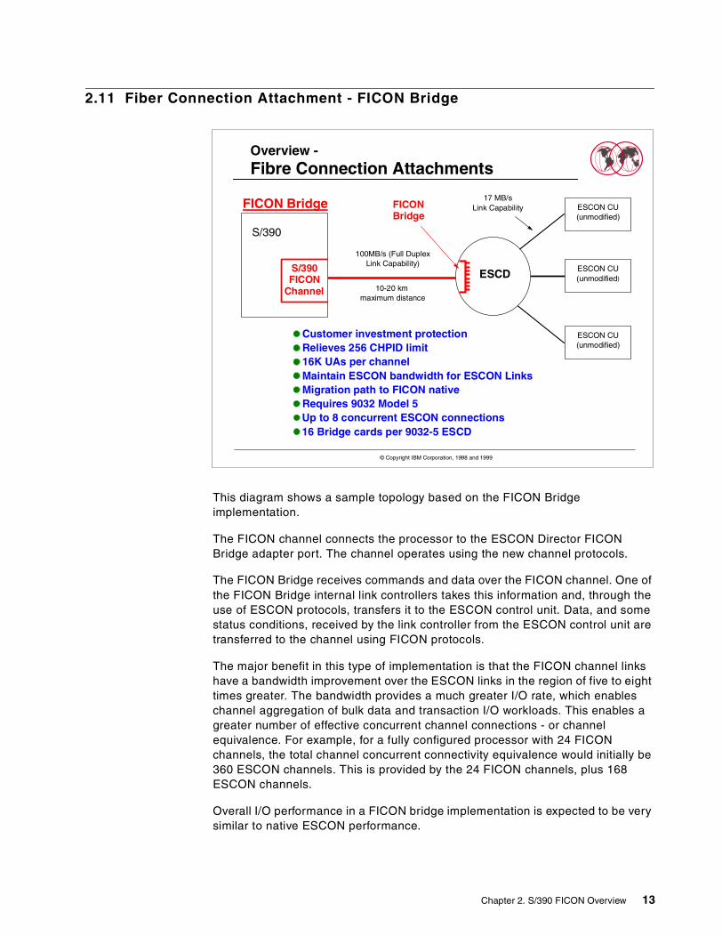
This diagram shows a sample topology based on the FICON Bridgeimplementation.
The FICON channel connects the processor to the ESCON Director FICONBridge adapter port. The channel operates using the new channel protocols.
The FICON Bridge receives commands and data over the FICON channel. One ofthe FICON Bridge internal link controllers takes this information and, through theuse of ESCON protocols, transfers it to the ESCON control unit. Data, and somestatus conditions, received by the link controller from the ESCON control unit aretransferred to the channel using FICON protocols.
The major benefit in this type of implementation is that the FICON channel linkshave a bandwidth improvement over the ESCON links in the region of five to eighttimes greater. The bandwidth provides a much greater I/O rate, which enableschannel aggregation of bulk data and transaction I/O workloads. This enables agreater number of effective concurrent channel connections - or channelequivalence. For example, for a fully configured processor with 24 FICONchannels, the total channel concurrent connectivity equivalence would initially be360 ESCON channels. This is provided by the 24 FICON channels, plus 168ESCON channels.
Overall I/O performance in a FICON bridge implementation is expected to be verysimilar to native ESCON performance.
Overview -Fibre Connection Attachments
Customer investment protectionRelieves 256 CHPID limit16K UAs per channelMaintain ESCON bandwidth for ESCON LinksMigration path to FICON nativeRequires 9032 Model 5Up to 8 concurrent ESCON connections16 Bridge cards per 9032-5 ESCD
S/390
100MB/s (Full DuplexLink Capability)
FICONBridge
17 MB/sLink Capability
ESCD10-20 km
maximum distance
FICON Bridge
S/390FICON
Channel
ESCON CU(unmodified)
ESCON CU(unmodified)
ESCON CU(unmodified)
© Copyright IBM Corporation, 1998 and 1999
Chapter 2. S/390 FICON Overview 13
An ESCON control unit can be connected to both ESCON channels (CNC) andFICON bridge channels (FCV). The two channel types can both be connected toand used by the same logical partition at the same time, to the same control unit.We sometimes refer to this as intermixing of channel types to the same controlunit from the same processor image.
2.12 FICON Native Configuration
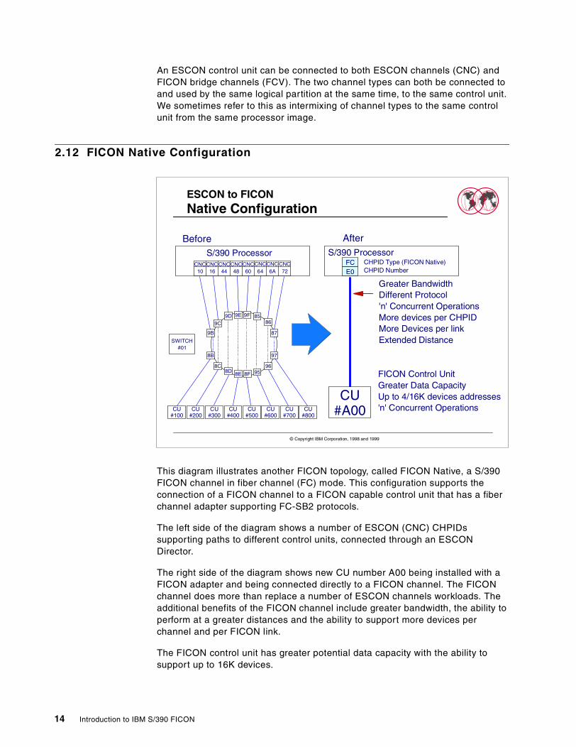
This diagram illustrates another FICON topology, called FICON Native, a S/390FICON channel in fiber channel (FC) mode. This configuration supports theconnection of a FICON channel to a FICON capable control unit that has a fiberchannel adapter supporting FC-SB2 protocols.
The left side of the diagram shows a number of ESCON (CNC) CHPIDssupporting paths to different control units, connected through an ESCONDirector.
The right side of the diagram shows new CU number A00 being installed with aFICON adapter and being connected directly to a FICON channel. The FICONchannel does more than replace a number of ESCON channels workloads. Theadditional benefits of the FICON channel include greater bandwidth, the ability toperform at a greater distances and the ability to support more devices perchannel and per FICON link.
The FICON control unit has greater potential data capacity with the ability tosupport up to 16K devices.
ESCON to FICONNative Configuration
Before
CNC10
CNCCNCCNCCNCCNC16 44 48 60 64
CNC CNC6A 72
S/390 Processor
SWITCH#01
CU#100
CU#200
CU#500
CU#600
CU#300
CU#400
CU#700
CU#800
9D 9E
958F
9F
8D 8E
9B
8B
9C
8C
8586
87
96
97
AfterS/390 Processor
FCE0
Greater BandwidthDifferent Protocol'n' Concurrent OperationsMore devices per CHPIDMore Devices per linkExtended Distance
CU#A00
FICON Control UnitGreater Data CapacityUp to 4/16K devices addresses'n' Concurrent Operations
CHPID Type (FICON Native)CHPID Number
© Copyright IBM Corporation, 1998 and 1999
14 Introduction to IBM S/390 FICON
FICON Native configurations are illustrated in more detail in the followingdiagrams.
2.13 Fiber Connection Attachment - FICON Direct
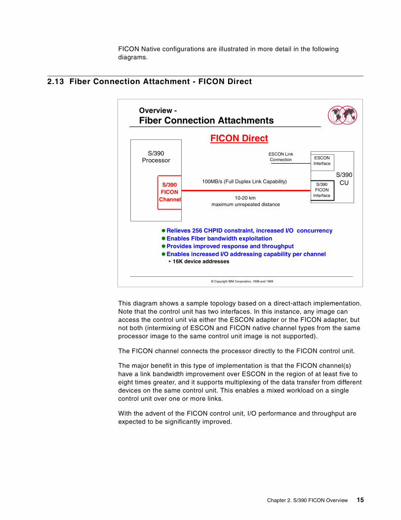
This diagram shows a sample topology based on a direct-attach implementation.Note that the control unit has two interfaces. In this instance, any image canaccess the control unit via either the ESCON adapter or the FICON adapter, butnot both (intermixing of ESCON and FICON native channel types from the sameprocessor image to the same control unit image is not supported).
The FICON channel connects the processor directly to the FICON control unit.
The major benefit in this type of implementation is that the FICON channel(s)have a link bandwidth improvement over ESCON in the region of at least five toeight times greater, and it supports multiplexing of the data transfer from differentdevices on the same control unit. This enables a mixed workload on a singlecontrol unit over one or more links.
With the advent of the FICON control unit, I/O performance and throughput areexpected to be significantly improved.
Relieves 256 CHPID constraint, increased I/O concurrencyEnables Fiber bandwidth exploitationProvides improved response and throughputEnables increased I/O addressing capability per channel
16K device addresses
Overview -Fiber Connection Attachments
FICON Direct
S/390FICON
Interface
S/390CU
ESCONInterface
S/390Processor
100MB/s (Full Duplex Link Capability)S/390FICON
Channel 10-20 kmmaximum unrepeated distance
© Copyright IBM Corporation, 1998 and 1999
ESCON LinkConnection
Chapter 2. S/390 FICON Overview 15
2.14 Fiber Connection Attachment - FICON Switch
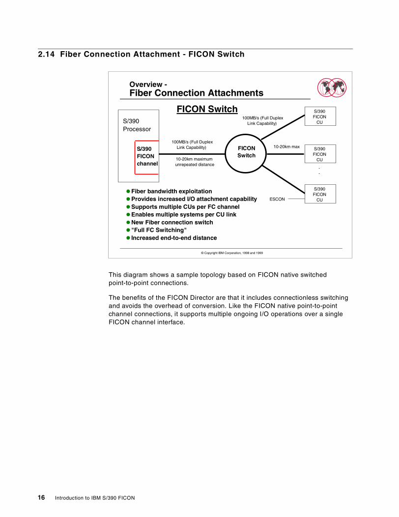
This diagram shows a sample topology based on FICON native switchedpoint-to-point connections.
The benefits of the FICON Director are that it includes connectionless switchingand avoids the overhead of conversion. Like the FICON native point-to-pointchannel connections, it supports multiple ongoing I/O operations over a singleFICON channel interface.
Overview -Fiber Connection Attachments
Fiber bandwidth exploitationProvides increased I/O attachment capabilitySupports multiple CUs per FC channelEnables multiple systems per CU linkNew Fiber connection switch"Full FC Switching"Increased end-to-end distance
FICON SwitchS/390Processor
S/390FICONchannel
100MB/s (Full DuplexLink Capability) 10-20km max
ESCON
FICONSwitch
S/390FICON
CU
S/390FICON
CU
.
.
.
S/390FICON
CU
100MB/s (Full DuplexLink Capability)
10-20km maximumunrepeated distance
© Copyright IBM Corporation, 1998 and 1999
16 Introduction to IBM S/390 FICON
2.15 Sample Implementation
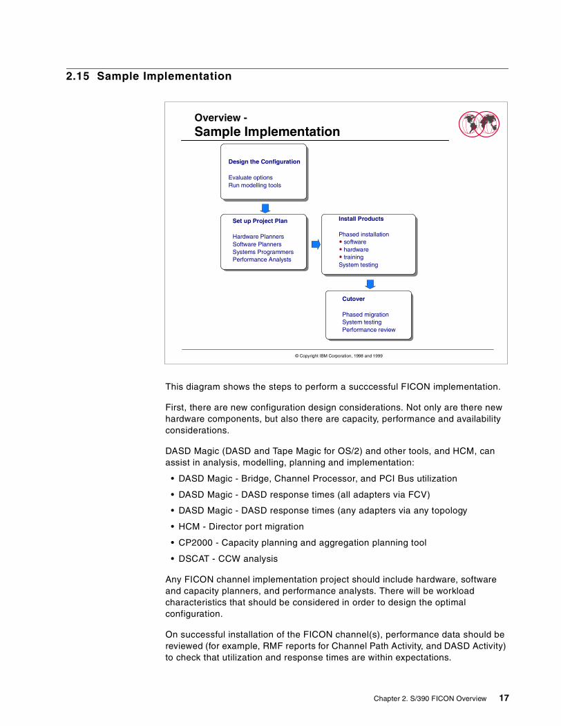
This diagram shows the steps to perform a succcessful FICON implementation.
First, there are new configuration design considerations. Not only are there newhardware components, but also there are capacity, performance and availabilityconsiderations.
DASD Magic (DASD and Tape Magic for OS/2) and other tools, and HCM, canassist in analysis, modelling, planning and implementation:
• DASD Magic - Bridge, Channel Processor, and PCI Bus utilization
• DASD Magic - DASD response times (all adapters via FCV)
• DASD Magic - DASD response times (any adapters via any topology
• HCM - Director port migration
• CP2000 - Capacity planning and aggregation planning tool
• DSCAT - CCW analysis
Any FICON channel implementation project should include hardware, softwareand capacity planners, and performance analysts. There will be workloadcharacteristics that should be considered in order to design the optimalconfiguration.
On successful installation of the FICON channel(s), performance data should bereviewed (for example, RMF reports for Channel Path Activity, and DASD Activity)to check that utilization and response times are within expectations.
Overview -Sample Implementation
Install Products
Phased installationsoftwarehardwaretraining
System testing
Cutover
Phased migrationSystem testingPerformance review
Design the Configuration
Evaluate optionsRun modelling tools
Set up Project Plan
Hardware PlannersSoftware PlannersSystems ProgrammersPerformance Analysts
© Copyright IBM Corporation, 1998 and 1999
Chapter 2. S/390 FICON Overview 17
2.16 Overview Summary
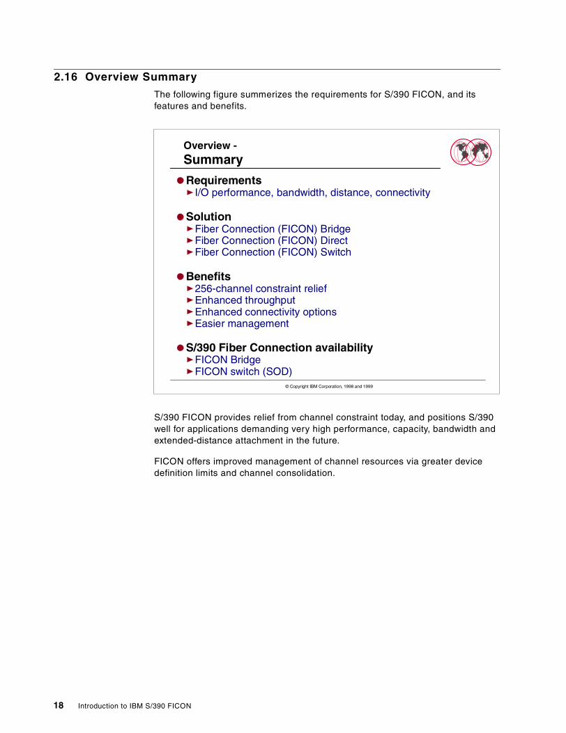
The following figure summerizes the requirements for S/390 FICON, and itsfeatures and benefits.
S/390 FICON provides relief from channel constraint today, and positions S/390well for applications demanding very high performance, capacity, bandwidth andextended-distance attachment in the future.
FICON offers improved management of channel resources via greater devicedefinition limits and channel consolidation.
Overview -Summary
RequirementsI/O performance, bandwidth, distance, connectivity
SolutionFiber Connection (FICON) BridgeFiber Connection (FICON) DirectFiber Connection (FICON) Switch
Benefits256-channel constraint reliefEnhanced throughputEnhanced connectivity optionsEasier management
S/390 Fiber Connection availabilityFICON BridgeFICON switch (SOD)
© Copyright IBM Corporation, 1998 and 1999
18 Introduction to IBM S/390 FICON
Chapter 3. Architecture Overview
This chapter provides an overview of IBM's new S/390 FICON architecture. S/390FICON architecture introduces new configurations, including the FICON Bridge,FICON Native, and FICON Director.
It describes why the development of a new architecture was necessary, definesthe new configurations, and discusses how this enhances existing S/390 I/Oarchitecture.
Among the FICON architecture improvements over the ESCON architecture:
• Increase from 16 to 256 CU Images per Link.
• Increase from 4K to 64K Device Addresses per Link.
3.1 Requirements for a New Architecture
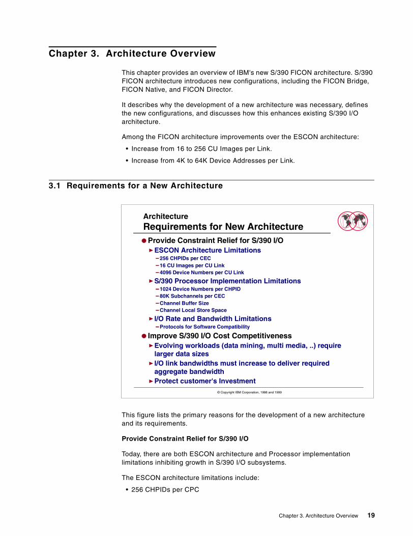
This figure lists the primary reasons for the development of a new architectureand its requirements.
Provide Constraint Relief for S/390 I/O
Today, there are both ESCON architecture and Processor implementationlimitations inhibiting growth in S/390 I/O subsystems.
The ESCON architecture limitations include:
• 256 CHPIDs per CPC
ArchitectureRequirements for New Architecture
Provide Constraint Relief for S/390 I/OESCON Architecture Limitations
256 CHPIDs per CEC16 CU Images per CU Link4096 Device Numbers per CU Link
S/390 Processor Implementation Limitations1024 Device Numbers per CHPID80K Subchannels per CECChannel Buffer SizeChannel Local Store Space
I/O Rate and Bandwidth LimitationsProtocols for Software Compatibility
Improve S/390 I/O Cost CompetitivenessEvolving workloads (data mining, multi media, ..) requirelarger data sizesI/O link bandwidths must increase to deliver requiredaggregate bandwidthProtect customer's Investment
© Copyright IBM Corporation, 1998 and 1999
Chapter 3. Architecture Overview 19

• 16 Control Unit Images per Control Unit Link
• 4096 Device Numbers per Control Unit Link.
The processor implementation limitations include:
• 1024 Device Numbers per CHPID
• 80K Subchannels per CPC
• Channel Buffer Size
• Channel Local Store Space
Improve S/390 I/O cost competitiveness
The requirements of a new architecture include providing for improved linkbandwidths, improved connectivity and larger data sizes, while protecting thecustomer investment in existing technology.
3.2 FICON Architecture
This lists presents the features of IBM's S/390 FICON architecture.
Fiber Connection Configuration
The S/390 FICON architectureand implementation introduces two newconfigurations:
• FICON Native
• FICON Director
ArchitectureS/390 FICON
IBM's FC-SB2 (S/390 FICON Architecture)Defines Fibre Channel Configurations
Fiber Channel Native (Direct connect or Switched)
Provides New FeaturesSupplements Existing S/390 I/O ArchitectureRelieves ESCON Architectural LimitationsIs Fully Compatible with Existing S/390 Software
Some software changes required to exploit new featuresSome software changes required for performance tuning andcapacity planning
The Fiber Channel Bridge configuration uses a modified version of thearchitecture
© Copyright IBM Corporation, 1998 and 1999
20 Introduction to IBM S/390 FICON
FICON Native provides for the attachment of a FICON channel directly to acontrol unit with a S/390 FICON interface.
A FICON channel supporting the direct attachment of a control unit is known aschannel type FC.
The FICON Director provides switched connections between FICON channelsand control units with FICON interfaces.
FICON Bridge
The FICON Bridge configuration uses a modified version of the new FICONarchitecture.
The FICON Bridge provides a bridge function on an ESCON Director that acceptsone FICON channel link from a FICON FCV mode channel and provides multipleinternal ESCON switch matrix connections to the ESCON director ports. FICONinformation received from the channel is converted to ESCON protocol by thebridge and some ESCON frames received from an ESCON control unit areconverted to FICON protocols.
The FICON channel supporting the bridge is defined as channel type FCV.
Each is shown in more detail on subsequent diagrams.
FICON - ESCON Supplement
The S/390 FICON architecture is an enhancement of, rather than a replacementfor, the existing ESCON architecture. S/390 FICON extends the channel distance,and retains the topology and some of the switch management characteristics ofESCON.
FICON - ESCON Extension
The new S/390 FICON architecture eliminates some of the limitations of theESCON architecture that are inhibitors to growth in the S/390 I/O subsystems oftoday. These extensions include a maximum of 256 control unit images perFICON link, and a maximum of 64K device numbers per FICON link.
FICON to ESCON Compatibility
Another feature of the S/390 FICON architecture is that it is fully compatible withexisting S/390 software. The new channel executes standard S/390 channelcommands (CCWs) and programs.
System software changes are required to exploit the new features of the S/390FICON architecture, as well as to manage performance tuning and capacityplanning.
Chapter 3. Architecture Overview 21
3.3 ESCON to FICON (FCV) Comparisons
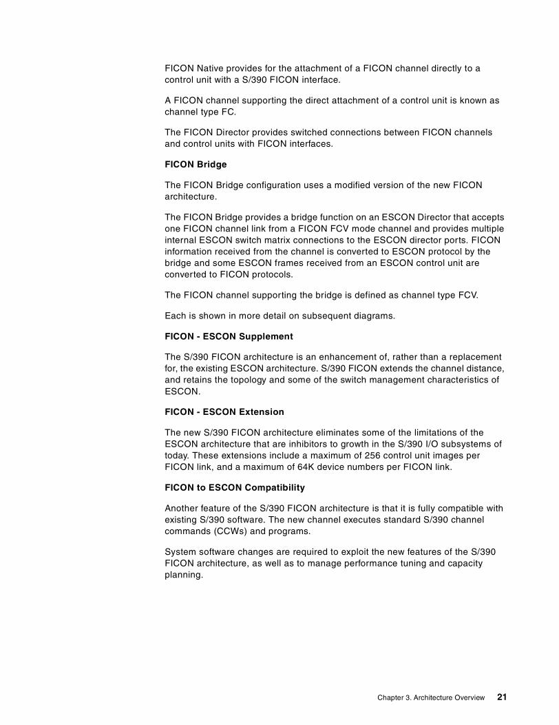
This table compares the features and capabilities of:
• S/390 ESCON architecture
• Implementation of the S/390 ESCON architecture in the IBM 9672 G5/G6processors
• Implementation of the S/390 FICON (FCV) architecture in the IBM 9672G5/G6 processors
These should be taken into account when designing and planning your S/390FICON (FCV mode) configurations.
ArchitectureESCON to FICON (FVC) Comparison
S/390ESCON
Architecture
S/390 9672ESCON
Implementation
S/390 9672FICON(Bridge)Implementation
# CHPIDs by type per CEC 256 256 24
ESCON & FICON (FCV) ChannelsEquivalence (8 Concurrent I/O)
42 ESCON Cards4 Chans/card = 168
(24x8) = 192
Total ESCON + FICON (FCV)Equivalent channels
64 ESCON Cards4 Chans/card=256
ESCON + FICON(FCV)(42x4)+(24x8)=360
# CU Links per Channel 253 1-120 1-120
# Control Unit Images (CUADD) perChannel/Control Unit Link 16 16 16
# Control Units per Channel 4048 120 120
# Device Addresses per Control Unit Image(per CUADD)
256 256 256
# Device Addresses per Control Unit Link 4096 1024 4096
# Device Addresses per Channel 64 K 1024 16384
# S/390 Subchannels (G5/G6)Total for a CPCMaximum for an LPAR
64 K80 K36 K
80 K36 K
Distances
Maximum distances with repeaters areCU-dependent
2 km - 50um Fiber3 km - 62.5 um Fiber
60 to 100 km Max(With Repeaters)
550m, 50/62.5um fiber10 km - 9 um Fiber
20 km - 9 um (RPQ)100 km tested Max
(With Repeaters)
Date transfer droop distance 9KM 100KM
© Copyright IBM Corporation, 1998 and 1999
22 Introduction to IBM S/390 FICON
3.4 ESCON Channel Command Processing
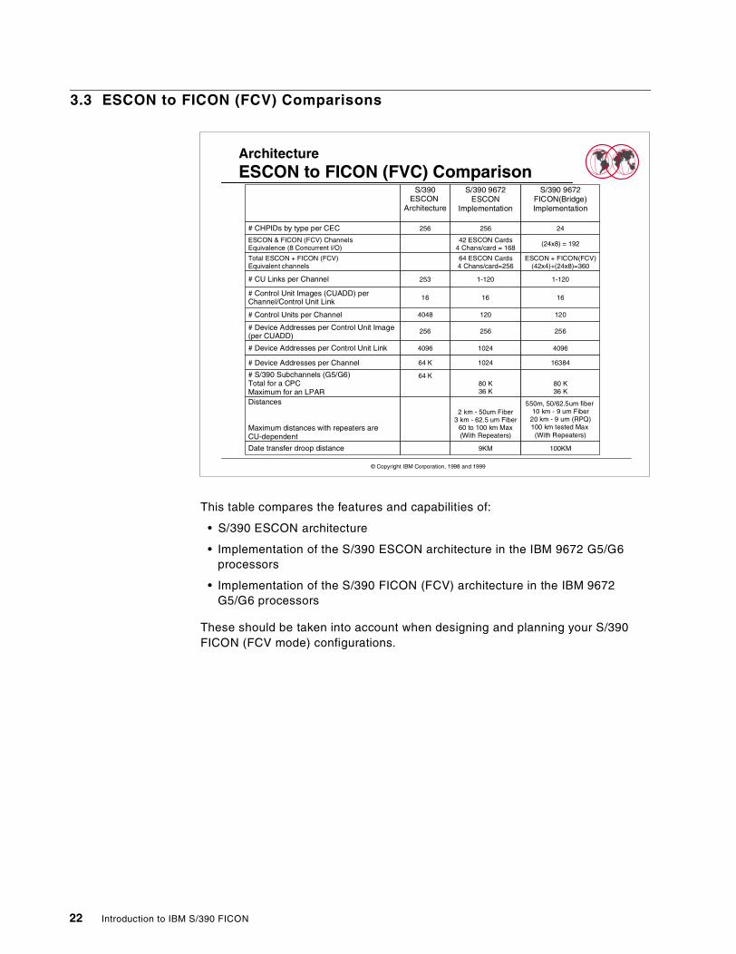
This diagram illustrates channel command and data transfer in the ESCONenvironment.
Each channel command sent from the ESCON channel to the control unit has tocomplete before the channel will send the next command. This requires anexchange of interlocking protocols for each command, and there are a number ofthese protocol exchanges during the transfer of the command and data for oneCCW. This hand shaking protocol increases the elapsed time for each CCW, andalong with the way that data frames are managed, it has a significant effect ondata transfer droop at greater channel to control unit distances.
With FICON (FCV) this same command processing occurs to the ESCON controlunit, but it is managed by the FICON Bridge adapter and not directly from thechannel. As there are 8 controllers in one FICON bridge adapter, there can be upto 8 of these command processing operations being managed concurrently at thesame time from one FICON (FCV) channel and the FICON Bridge adapter, to 8different control units.
ArchitectureESCON - Channel Command Processing
Channel Control UnitCCW1
Device
End
EndCE/DE
CE/DE
CE/DE
End
ESCON Command and Data Transfer
CCW2
CCW3
CCW1
CCW2
CCW3
CCW1
CCW2
CCW3
CCW1
CCW2
CCW3
© Copyright IBM Corporation, 1998 and 1999
Chapter 3. Architecture Overview 23

24 Introduction to IBM S/390 FICON
Chapter 4. FICON Cabling
In this chapter the following topics are discussed:
• Supported FICON Fiber cabling
• S/390 Fiber Cabling and FOSA (Fiber Optic Sub Assembly) requirements andcharacteristics
• FICON Fiber cabling requirements for FICON channels connected to a FICONBridge adapter
• FICON channel direct attach to FICON Bridge adapter
• FICON channel attach via patch panels to FICON Bridge adapter
• FICON Fiber cabling requirements for remote I/O connections
• Trunk fiber re-use, FICON Fiber cabling requirements
4.1 FICON Fiber Cabling
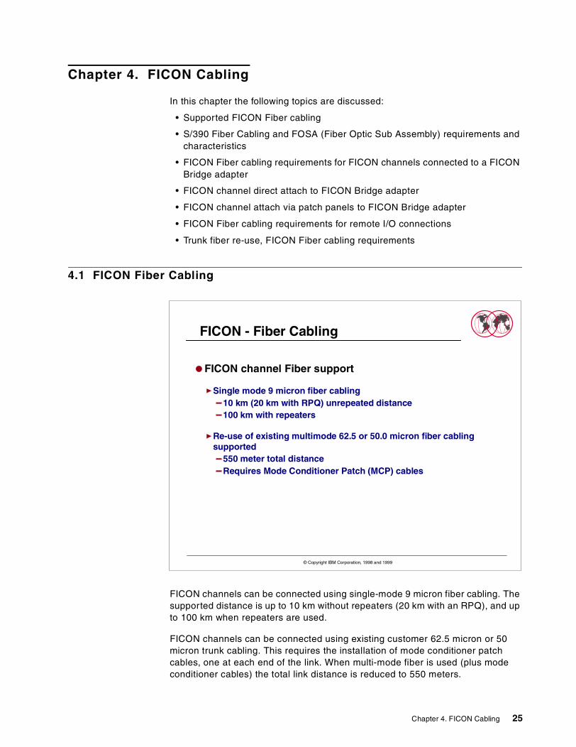
FICON channels can be connected using single-mode 9 micron fiber cabling. Thesupported distance is up to 10 km without repeaters (20 km with an RPQ), and upto 100 km when repeaters are used.
FICON channels can be connected using existing customer 62.5 micron or 50micron trunk cabling. This requires the installation of mode conditioner patchcables, one at each end of the link. When multi-mode fiber is used (plus modeconditioner cables) the total link distance is reduced to 550 meters.
FICON - Fiber Cabling
FICON channel Fiber support
Single mode 9 micron fiber cabling10 km (20 km with RPQ) unrepeated distance100 km with repeaters
Re-use of existing multimode 62.5 or 50.0 micron fiber cablingsupported
550 meter total distanceRequires Mode Conditioner Patch (MCP) cables
© Copyright IBM Corporation, 1998 and 1999
Chapter 4. FICON Cabling 25
4.2 Cabling Requirements
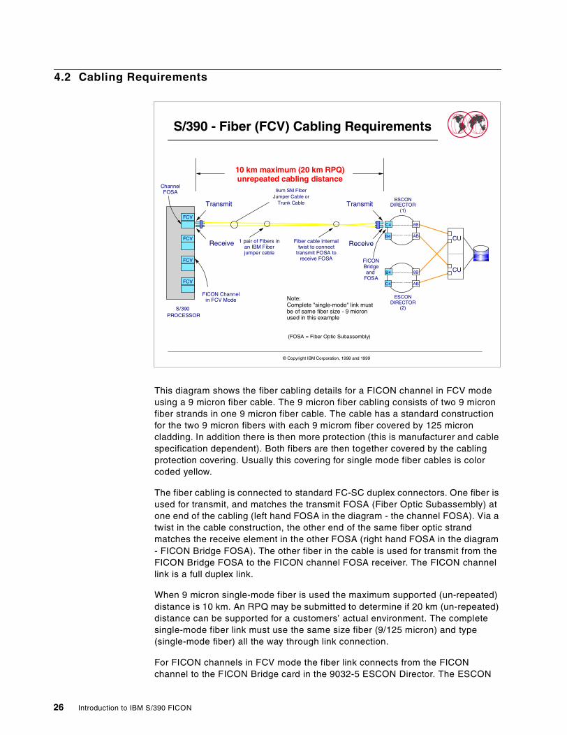
This diagram shows the fiber cabling details for a FICON channel in FCV modeusing a 9 micron fiber cable. The 9 micron fiber cabling consists of two 9 micronfiber strands in one 9 micron fiber cable. The cable has a standard constructionfor the two 9 micron fibers with each 9 microm fiber covered by 125 microncladding. In addition there is then more protection (this is manufacturer and cablespecification dependent). Both fibers are then together covered by the cablingprotection covering. Usually this covering for single mode fiber cables is colorcoded yellow.
The fiber cabling is connected to standard FC-SC duplex connectors. One fiber isused for transmit, and matches the transmit FOSA (Fiber Optic Subassembly) atone end of the cabling (left hand FOSA in the diagram - the channel FOSA). Via atwist in the cable construction, the other end of the same fiber optic strandmatches the receive element in the other FOSA (right hand FOSA in the diagram- FICON Bridge FOSA). The other fiber in the cable is used for transmit from theFICON Bridge FOSA to the FICON channel FOSA receiver. The FICON channellink is a full duplex link.
When 9 micron single-mode fiber is used the maximum supported (un-repeated)distance is 10 km. An RPQ may be submitted to determine if 20 km (un-repeated)distance can be supported for a customers’ actual environment. The completesingle-mode fiber link must use the same size fiber (9/125 micron) and type(single-mode fiber) all the way through link connection.
For FICON channels in FCV mode the fiber link connects from the FICONchannel to the FICON Bridge card in the 9032-5 ESCON Director. The ESCON
S/390 - Fiber (FCV) Cabling Requirements
S/390PROCESSOR
FCV
FCV
C4
ABB4
8B
B4
ABC4
8B
ESCONDIRECTOR
(1)
ESCONDIRECTOR
(2)
10 km maximum (20 km RPQ)unrepeated cabling distance
9um SM FiberJumper Cable or
Trunk Cable
1 pair of Fibers inan IBM Fiberjumper cable
Note:Complete "single-mode" link mustbe of same fiber size - 9 micronused in this example
FCV
FCV
CU
CU
Transmit
Receive
Transmit
ReceiveFiber cable internaltwist to connect
transmit FOSA toreceive FOSA
ChannelFOSA
(FOSA = Fiber Optic Subassembly)
FICONBridgeand
FOSA
© Copyright IBM Corporation, 1998 and 1999
FICON Channelin FCV Mode
26 Introduction to IBM S/390 FICON
link from the 9032-5 to the S/390 control unit requires the use of standardESCON cabling. This is either 62.5/125 micron or 50.0/125 micron multi-modefiber cabling. Standard ESCON link distances (un-repeated) are supported forthis link, which is, 3 km for 62.5/125 micron multi-mode fiber or 2 km when50.0/125 micron multi-mode fiber is used.
4.3 FICON FCV Configuration
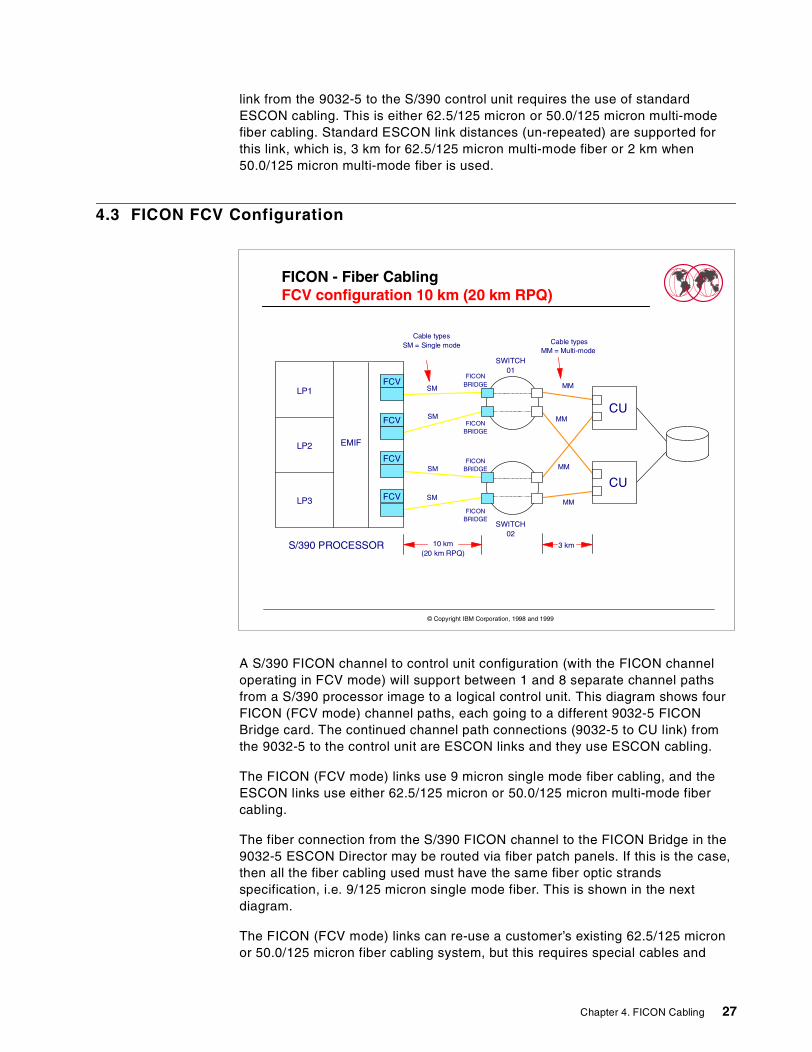
A S/390 FICON channel to control unit configuration (with the FICON channeloperating in FCV mode) will support between 1 and 8 separate channel pathsfrom a S/390 processor image to a logical control unit. This diagram shows fourFICON (FCV mode) channel paths, each going to a different 9032-5 FICONBridge card. The continued channel path connections (9032-5 to CU link) fromthe 9032-5 to the control unit are ESCON links and they use ESCON cabling.
The FICON (FCV mode) links use 9 micron single mode fiber cabling, and theESCON links use either 62.5/125 micron or 50.0/125 micron multi-mode fibercabling.
The fiber connection from the S/390 FICON channel to the FICON Bridge in the9032-5 ESCON Director may be routed via fiber patch panels. If this is the case,then all the fiber cabling used must have the same fiber optic strandsspecification, i.e. 9/125 micron single mode fiber. This is shown in the nextdiagram.
The FICON (FCV mode) links can re-use a customer’s existing 62.5/125 micronor 50.0/125 micron fiber cabling system, but this requires special cables and
FICON - Fiber CablingFCV configuration 10 km (20 km RPQ)
S/390 PROCESSOR
FCV
FCV
EMIF
LP1
LP2
LP3
SWITCH02
CU
CU
SWITCH01
FICONBRIDGE
SM
SM
SM
SM
Cable typesSM = Single mode
MM
MM
MM
MM
FCV
FCV
FICONBRIDGE
FICONBRIDGE
FICONBRIDGE
Cable typesMM = Multi-mode
10 km(20 km RPQ)
3 km
© Copyright IBM Corporation, 1998 and 1999
Chapter 4. FICON Cabling 27
connectors. See 4.5, “Fiber Cabling Types” on page 29 and 4.6, “Fiber CableRe-use” on page 30 for details of the use of this type of fiber connection.
4.4 Fiber Cabling Connect
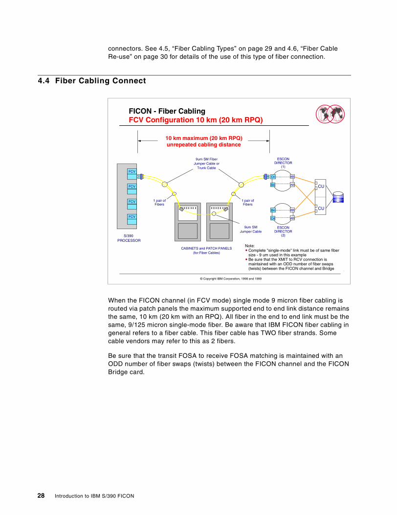
When the FICON channel (in FCV mode) single mode 9 micron fiber cabling isrouted via patch panels the maximum supported end to end link distance remainsthe same, 10 km (20 km with an RPQ). All fiber in the end to end link must be thesame, 9/125 micron single-mode fiber. Be aware that IBM FICON fiber cabling ingeneral refers to a fiber cable. This fiber cable has TWO fiber strands. Somecable vendors may refer to this as 2 fibers.
Be sure that the transit FOSA to receive FOSA matching is maintained with anODD number of fiber swaps (twists) between the FICON channel and the FICONBridge card.
FICON - Fiber CablingFCV Configuration 10 km (20 km RPQ)
S/390PROCESSOR
FCV
FCV
C4
ABB4
8B
B4
ABC4
8B
ESCONDIRECTOR
(1)
ESCONDIRECTOR
(2)
CABINETS and PATCH PANELS(for Fiber Cables)
10 km maximum (20 km RPQ)unrepeated cabling distance
9um SM FiberJumper Cable or
Trunk Cable
1 pair ofFibers
1 pair ofFibers
Note:Complete "single-mode" link must be of same fibersize - 9 um used in this exampleBe sure that the XMIT to RCV connection ismaintained with an ODD number of fiber swaps(twists) between the FICON channel and Bridge
9um SMJumper Cable
FCV
FCV
CU
CU
© Copyright IBM Corporation, 1998 and 1999
28 Introduction to IBM S/390 FICON
4.5 Fiber Cabling Types
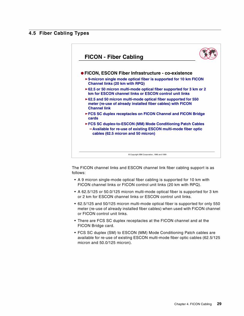
The FICON channel links and ESCON channel link fiber cabling support is asfollows:
• A 9 micron single-mode optical fiber cabling is supported for 10 km withFICON channel links or FICON control unit links (20 km with RPQ).
• A 62.5/125 or 50.0/125 micron multi-mode optical fiber is supported for 3 kmor 2 km for ESCON channel links or ESCON control unit links.
• 62.5/125 and 50/125 micron multi-mode optical fiber is supported for only 550meter (re-use of already installed fiber cables) when used with FICON channelor FICON control unit links.
• There are FCS SC duplex receptacles at the FICON channel and at theFICON Bridge card.
• FCS SC duplex (SM) to ESCON (MM) Mode Conditioning Patch cables areavailable for re-use of existing ESCON multi-mode fiber optic cables (62.5/125micron and 50.0/125 micron).
FICON - Fiber Cabling
FICON, ESCON Fiber Infrastructure - co-existence9-micron single mode optical fiber is supported for 10 km FICONChannel links (20 km with RPQ)
62.5 or 50 micron multi-mode optical fiber supported for 3 km or 2km for ESCON channel links or ESCON control unit links
62.5 and 50 micron multi-mode optical fiber supported for 550meter (re-use of already installed fiber cables) with FICONChannel link
FCS SC duplex receptacles on FICON Channel and FICON Bridgecards
FCS SC duplex-to-ESCON (MM) Mode Conditioning Patch CablesAvailable for re-use of existing ESCON multi-mode fiber opticcables (62.5 micron and 50 micron)
© Copyright IBM Corporation, 1998 and 1999
Chapter 4. FICON Cabling 29
4.6 Fiber Cable Re-use
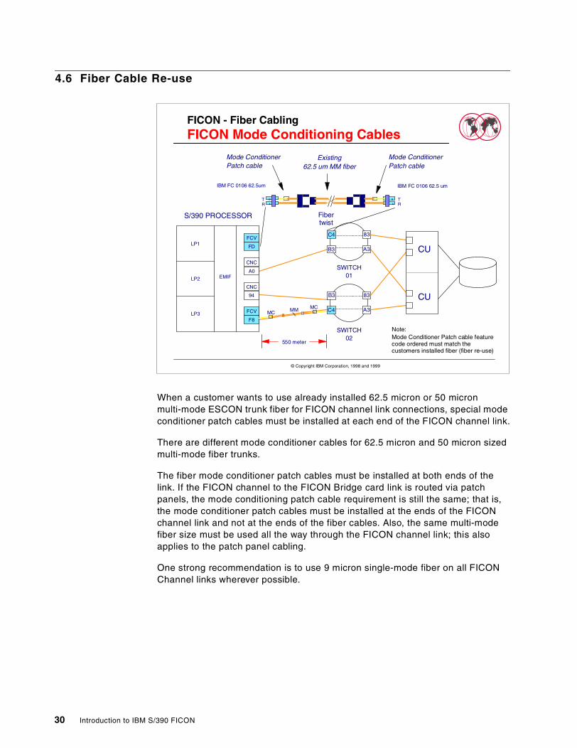
When a customer wants to use already installed 62.5 micron or 50 micronmulti-mode ESCON trunk fiber for FICON channel link connections, special modeconditioner patch cables must be installed at each end of the FICON channel link.
There are different mode conditioner cables for 62.5 micron and 50 micron sizedmulti-mode fiber trunks.
The fiber mode conditioner patch cables must be installed at both ends of thelink. If the FICON channel to the FICON Bridge card link is routed via patchpanels, the mode conditioning patch cable requirement is still the same; that is,the mode conditioner patch cables must be installed at the ends of the FICONchannel link and not at the ends of the fiber cables. Also, the same multi-modefiber size must be used all the way through the FICON channel link; this alsoapplies to the patch panel cabling.
One strong recommendation is to use 9 micron single-mode fiber on all FICONChannel links wherever possible.
FICON - Fiber CablingFICON Mode Conditioning Cables
FD
FCV
F8
FCV
A0
CNC
94
CNC
EMIF
LP1
LP2
LP3
SWITCH02
C4
A3B3
83
B3
A3C4
83
SWITCH01
Mode ConditionerPatch cable
Mode ConditionerPatch cable
Existing62.5 um MM fiber
S/390 PROCESSOR
B
A
MCMCMM
A
B
IBM FC 0106 62.5 um
Note:Mode Conditioner Patch cable featurecode ordered must match thecustomers installed fiber (fiber re-use)
550 meter
IBM FC 0106 62.5um
TR
TR
CU
CU
Fibertwist
© Copyright IBM Corporation, 1998 and 1999
30 Introduction to IBM S/390 FICON
4.7 Fiber Mode Conditioner Patch Cables
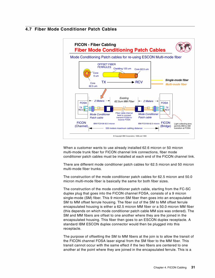
When a customer wants to use already installed 62.6 micron or 50 micronmulti-mode trunk fiber for FICON channel link connections, fiber modeconditioner patch cables must be installed at each end of the FICON channel link.
There are different mode conditioner patch cables for 62.5 micron and 50 micronmulti-mode fiber trunks.
The construction of the mode conditioner patch cables for 62.5 micron and 50.0micron multi-mode fiber is basically the same for both fiber sizes.
The construction of the mode conditioner patch cable, starting from the FC-SCduplex plug that goes into the FICON channel FOSA, consists of a 9 micronsingle-mode (SM) fiber. This 9 micron SM fiber then goes into an encapsulatedSM to MM offset ferrule housing. The fiber out of the SM to MM offset ferruleencapsulated housing is either a 62.5 micron MM fiber or a 50.0 micron MM fiber(this depends on which mode conditioner patch cable MM size was ordered). TheSM and MM fibers are offset to one another where they are the joined in theencapsulated housing. This fiber then goes to an ESCON duplex receptacle. Astandard IBM ESCON duplex connector would then be plugged into thisreceptacle.
The purpose of offsetting the SM to MM fibers at the join is to allow the transit ofthe FICON channel FOSA laser signal from the SM fiber to the MM fiber. Thistransit cannot occur with the same effect if the two fibers are centered to oneanother at the point where they are joined in the encapsulated ferrule. This is a
FICON - Fiber CablingFiber Mode Conditioning Patch Cables
OFFSET FIBERFERRULES
TX RCV
Mode ConditionerPatch cable
Mode ConditionerPatch cable
Existing62.5um MM Fiber
FICON(Channel)
Single-mode fiber
Multi-mode fiber
550 meters maximum cabling distance
Mode Conditioning Patch cables for re-using ESCON Multi-mode fiber
2 Meters2 Meters
IBM FC0106 62.5 micron IBM FC0106 62.5 micron
Cladding 125 um Core 62.5 um
Core9 um
Core62.5 um
FICON(Bridge)
Fiber cable internaltwist to connect
transmit FOSA toreceive FOSA
Light collecting lenspermits MM-to-SMtransition at FOSA
TXRCV
FOSA
TXRCV
FOSA
© Copyright IBM Corporation, 1998 and 1999
Chapter 4. FICON Cabling 31

property of fiber optics determined by the behavior of light at differentwavelengths when transiting different fiber types.
However a longwave (LX) laser signal travelling in 62.5 micron or 50.0 micronmulti-mode fiber has greater attenuation than if it were travelling in a 9 micronsignal-mode fiber. Because of this the supported distance between the FICONchannel FOSA and the FICON Bridge FOSA is limited (reduced) to 550 meters.
4.8 Fiber Cabling Remote Sites Benefits
When connecting FICON channels (in FCV mode) from a processor in one site toESCON connected I/O control units in another site (a remote site), it isrecommended to extend the FICON links and install 9 micron single mode fiberbetween the two sites when working with ESCON interface control units.Extending the FICON links and installing single-mode fiber between the sites willrequire less fiber connections between the two sites to support the same I/Oconnectivity than it would if the ESCON links were where the links that were beingextended, and it will provide for greater un-repeated distances.
FICON - Fiber CablingFICON and Remote I/O Sites
For FICON connection between remote sitesConnect Site A CPC to Site B ESCD FICON BridgeUse Single Mode 9 micron fiber for FICON linksConnect Site B CPC to Site A ESCD FICON BridgeUse Single Mode 9 micron fiber for FICON links
BenefitsLess Fiber cable connections between sites
Up to 8 times more for ESCON links
Unrepeated distance between sites 10 km (20 km with RPQ)ESCON unrepeated distance is 3 km
Greater distances before droop effectESCON droop about 9 km, FICON droop about 100 km
© Copyright IBM Corporation, 1998 and 1999
32 Introduction to IBM S/390 FICON
4.9 FICON Remote Site Configuration
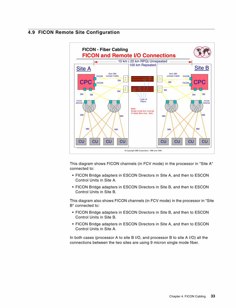
This diagram shows FICON channels (in FCV mode) in the processor in "Site A"connected to:
• FICON Bridge adapters in ESCON Directors in Site A, and then to ESCONControl Units in Site A.
• FICON Bridge adapters in ESCON Directors in Site B, and then to ESCONControl Units in Site B.
This diagram also shows FICON channels (in FCV mode) in the processor in "SiteB" connected to:
• FICON Bridge adapters in ESCON Directors in Site B, and then to ESCONControl Units in Site B.
• FICON Bridge adapters in ESCON Directors in Site A, and then to ESCONControl Units in Site A.
In both cases (processor A to site B I/O, and processor B to site A I/O) all theconnections between the two sites are using 9 micron single mode fiber.
FICON - Fiber CablingFICON and Remote I/O Connections
10 km ( 20 km RPQ) Unrepeated100 km Repeated
Note:Single-mode link must beof same fiber size - 9um
1 pair ofFibers
Site A
SM
MM
SM
MM
MM
MM
CPCFICON
FICON
CU CU CU CU
SMSM
FICONBRIDGE
9um SMJumper Cable
Site B
SM
MM
SM
MM
MM
MM
CPCFICON
FICON
CUCUCUCU
SM SM
FICONBRIDGE
9um SMJumper Cable
© Copyright IBM Corporation, 1998 and 1999
Chapter 4. FICON Cabling 33
4.10 S/390 Fiber Cabling Requirements
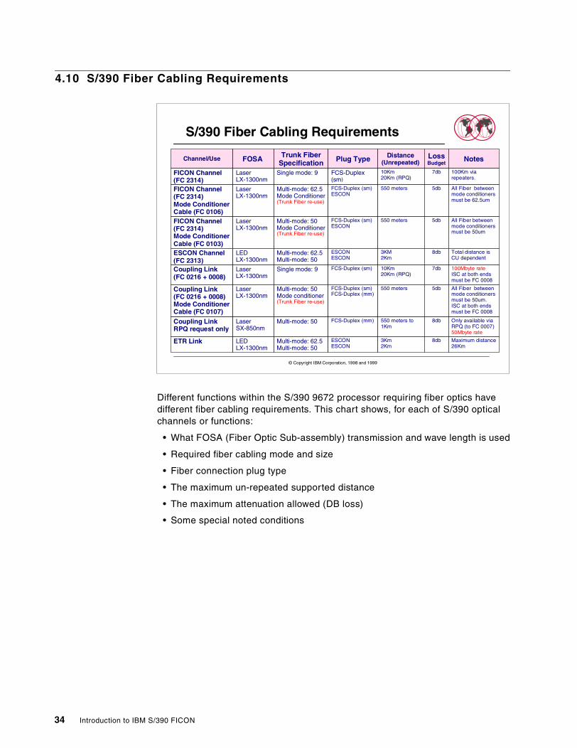
Different functions within the S/390 9672 processor requiring fiber optics havedifferent fiber cabling requirements. This chart shows, for each of S/390 opticalchannels or functions:
• What FOSA (Fiber Optic Sub-assembly) transmission and wave length is used
• Required fiber cabling mode and size
• Fiber connection plug type
• The maximum un-repeated supported distance
• The maximum attenuation allowed (DB loss)
• Some special noted conditions
S/390 Fiber Cabling Requirements
© Copyright IBM Corporation, 1998 and 1999
Channel/Use FOSA Trunk FiberSpecification Plug Type Distance
(Unrepeated)LossBudget
Notes
FICON Channel(FC 2314)
LaserLX-1300nm
Single mode: 9 FCS-Duplex(sm)
10Km20Km (RPQ)
7db 100Km viarepeaters.
FICON Channel(FC 2314)Mode ConditionerCable (FC 0106)
LaserLX-1300nm
Multi-mode: 62.5Mode Conditioner(Trunk Fiber re-use)
FCS-Duplex (sm)ESCON
550 meters 5db All Fiber betweenmode conditionersmust be 62.5um
FICON Channel(FC 2314)Mode ConditionerCable (FC 0103)
LaserLX-1300nm
Multi-mode: 50Mode Conditioner(Trunk Fiber re-use)
FCS-Duplex (sm)ESCON
550 meters 5db All Fiber betweenmode conditionersmust be 50um
ESCON Channel(FC 2313)
LEDLX-1300nm
Multi-mode: 62.5Multi-mode: 50
ESCONESCON
3KM2Km
8db Total distance isCU dependent
Coupling Link(FC 0216 + 0008)
LaserLX-1300nm
Single mode: 9 FCS-Duplex (sm) 10Km20Km (RPQ)
7db 100Mbyte rateISC at both endsmust be FC 0008
Coupling Link(FC 0216 + 0008)Mode ConditionerCable (FC 0107)
LaserLX-1300nm
Multi-mode: 50Mode conditioner(Trunk Fiber re-use)
FCS-Duplex (sm)FCS-Duplex (mm)
550 meters 5db All Fiber betweenmode conditionersmust be 50um.ISC at both endsmust be FC 0008
Coupling LinkRPQ request only
LaserSX-850nm
Multi-mode: 50 FCS-Duplex (mm) 550 meters to1Km
8db Only available viaRPQ (to FC 0007)50Mbyte rate
ETR Link LEDLX-1300nm
Multi-mode: 62.5Multi-mode: 50
ESCONESCON
3Km2Km
8db Maximum distance26Km
34 Introduction to IBM S/390 FICON
Chapter 5. ESCON to FICON Migration Tips
This chapter provides some tips that can be taken into consideration as you arethinking of preparing to migrate to a FICON environment.
5.1 Ahead of Migration
Things to do now:
Plan your 9672 I/O slots and CHPID numbers
For 9672 processors that do not have any installed FICON or OSA-Expresschannels, avoid using I/O channel slots. For example, avoid I/O slots 31, 06, 32,07 in I/O cage 3 of a 3 I/O cage machine, or I/O slots 31, 06, 32, 07 33, 34 in I/Ocages 1 or 2 in a one or two I/O cage machine. Also avoid using channel CHPIDnumbers in the range of CHPID numbers FC to FF and F8 to FB (for machineswithout ICB channels) that will be assigned to future channel types. Having I/Odomain channels installed in I/O slots that will be used for FICON, OSA-E or PCIcrypto channel types, or having channels installed in I/O slots whose CHPIDnumbers assigned to the I/O slot will be reassigned for future channel types, canoccur on systems that have installed non-FICON or OSA-Express channel typesin all 64 I/O slots.
Each FICON channel uses just one CHPID number, but the FICON CHPIDnumbers are assigned for FICON channels in groups of 4 (modulo 4). The otherthree CHPID numbers will be used when additional FICON channels (orOSA-Express, or PCI crypto channels) are installed.
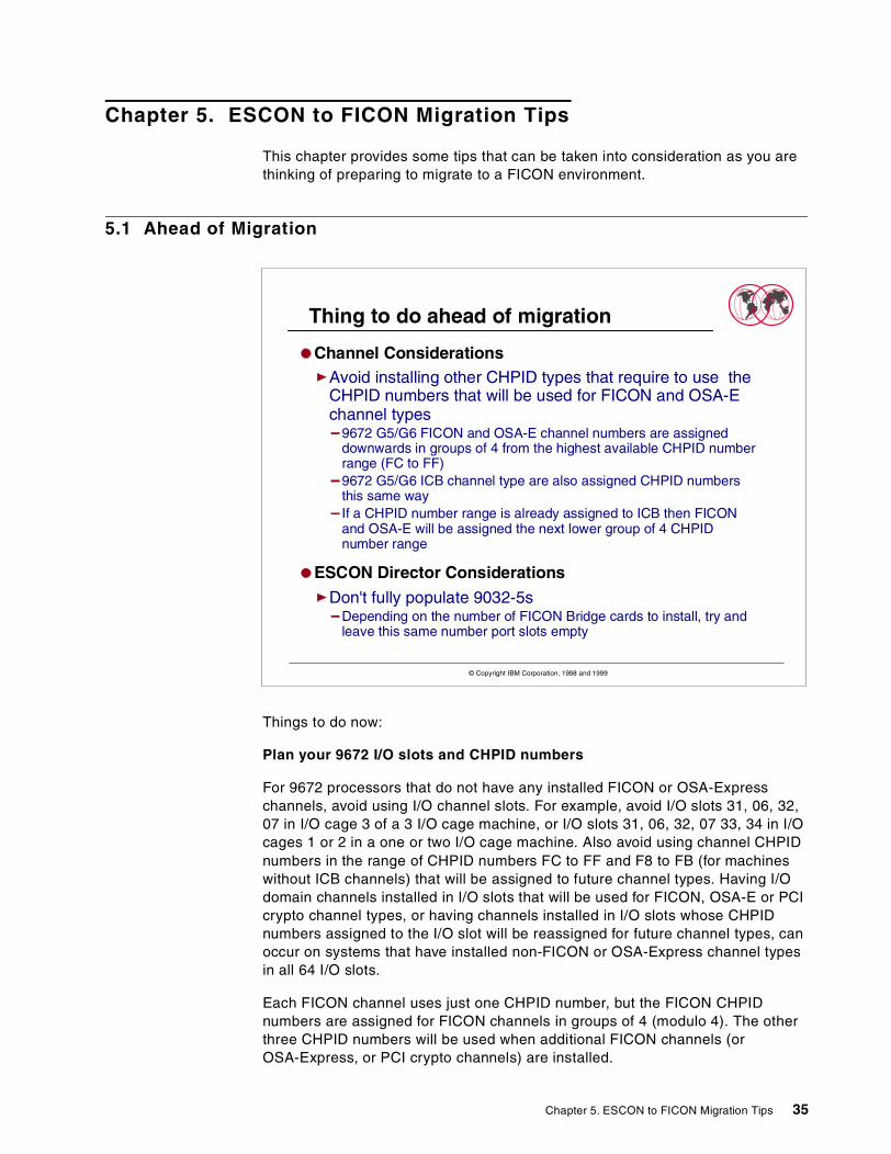
Thing to do ahead of migration
Channel ConsiderationsAvoid installing other CHPID types that require to use theCHPID numbers that will be used for FICON and OSA-Echannel types
9672 G5/G6 FICON and OSA-E channel numbers are assigneddownwards in groups of 4 from the highest available CHPID numberrange (FC to FF)9672 G5/G6 ICB channel type are also assigned CHPID numbersthis same wayIf a CHPID number range is already assigned to ICB then FICONand OSA-E will be assigned the next lower group of 4 CHPIDnumber range
ESCON Director Considerations
Don't fully populate 9032-5sDepending on the number of FICON Bridge cards to install, try andleave this same number port slots empty
© Copyright IBM Corporation, 1998 and 1999
Chapter 5. ESCON to FICON Migration Tips 35

ESCON Director considerations
Don't fully populate your 9032 Model 5s with ESCON port cards. Instead, leavespare slots for the future install of the FICON Bridge card. The FICON Bridgecard may be installed in any 9032-5 ESCON Director port slot, but there arerecommendations as to where they should be installed. Refer to the IBM FICONPlanning Guide - SG24-5445 for these recommendations.
Try to leave some empty ESCON Director port card slots for the future install ofFICON Bridge cards, or if all the ESCON Director port card slots are occupied tryto avoid using all the ports on an ESCON port card so that its future removal willbe less disruptive. Or, start now to stop using some of the ESCON ports (any ofthe ESCON ports in the same ESCON director will do) in quantities of 8. This willallow for the future movement of ESCON ports to free up an ESCON port cardslot or slots. The FICON Bridge card can be installed in that port card slot.
A FICON Bridge occupies one ESCON port card slot. Each ESCON port card slotis assigned 8 port addresses, but the FICON Bridge card only uses the first portaddress of the port addresses assigned to the port card slot. This statementassumes that default port address assignments are being used.
36 Introduction to IBM S/390 FICON
Appendix A. Special Notices
This publication is intended to help S/390 I/O Configuration planners and S/390I/O Capacity planners to develop an understanding of FICON and FICONarchitecture.
References in this publication to IBM products, programs or services do not implythat IBM intends to make these available in all countries in which IBM operates.Any reference to an IBM product, program, or service is not intended to state orimply that only IBM's product, program, or service may be used. Any functionallyequivalent program that does not infringe any of IBM's intellectual property rightsmay be used instead of the IBM product, program or service.
Information in this book was developed in conjunction with use of the equipmentspecified, and is limited in application to those specific hardware and softwareproducts and levels.
IBM may have patents or pending patent applications covering subject matter inthis document. The furnishing of this document does not give you any license tothese patents. You can send license inquiries, in writing, to the IBM Director ofLicensing, IBM Corporation, North Castle Drive, Armonk, NY 10504-1785.
Licensees of this program who wish to have information about it for the purposeof enabling: (i) the exchange of information between independently createdprograms and other programs (including this one) and (ii) the mutual use of theinformation which has been exchanged, should contact IBM Corporation, Dept.600A, Mail Drop 1329, Somers, NY 10589 USA.
Such information may be available, subject to appropriate terms and conditions,including in some cases, payment of a fee.
The information contained in this document has not been submitted to any formalIBM test and is distributed AS IS. The use of this information or theimplementation of any of these techniques is a customer responsibility anddepends on the customer's ability to evaluate and integrate them into thecustomer's operational environment. While each item may have been reviewed byIBM for accuracy in a specific situation, there is no guarantee that the same orsimilar results will be obtained elsewhere. Customers attempting to adapt thesetechniques to their own environments do so at their own risk.
Any pointers in this publication to external Web sites are provided forconvenience only and do not in any manner serve as an endorsement of theseWeb sites.
Any performance data contained in this document was determined in a controlledenvironment, and therefore, the results that may be obtained in other operatingenvironments may vary significantly. Users of this document should verify theapplicable data for their specific environment.
The following terms are trademarks of the International Business MachinesCorporation in the United States and/or other countries:
Enterprise Systems Architecture/390 ESA/390ESCON FICONIBM MVS/ESA
© Copyright IBM Corp. 1999 37

The following terms are trademarks of other companies:
C-bus is a trademark of Corollary, Inc. in the United States and/or other countries.
Java and all Java-based trademarks and logos are trademarks or registeredtrademarks of Sun Microsystems, Inc. in the United States and/or other countries.
Microsoft, Windows, Windows NT, and the Windows logo are trademarks ofMicrosoft Corporation in the United States and/or other countries.
PC Direct is a trademark of Ziff Communications Company in the United Statesand/or other countries and is used by IBM Corporation under license.
ActionMedia, LANDesk, MMX, Pentium and ProShare are trademarks of IntelCorporation in the United States and/or other countries.
UNIX is a registered trademark in the United States and/or other countrieslicensed exclusively through X/Open Company Limited.
SET and the SET logo are trademarks owned by SET Secure ElectronicTransaction LLC.
Other company, product, and service names may be trademarks or service marksof others.
OS/390 S/370S/390 S/390 Parallel Enterprise ServerSysplex Timer System/360System/370 System/390
38 Introduction to IBM S/390 FICON
Appendix B. Related Publications
The publications listed in this section are considered particularly suitable for amore detailed discussion of the topics covered in this redbook.
B.1 International Technical Support Organization Publications
For information on ordering these ITSO publications see “How to Get ITSORedbooks” on page 41.
• FICON Planning, SG24-5445
• FICON Implementation, SG24-5169
• IBM 9032-5 ESCON Director Presentation, SG24-2005
B.2 Redbooks on CD-ROMs
Redbooks are also available on the following CD-ROMs. Click the CD-ROMsbutton at http://www.redbooks.ibm.com/ for information about all the CD-ROMsoffered, updates and formats.
B.3 Other Publications
These publications are also relevant as further information sources:
• FICON Physical Layer, SA24-7172
• Planning for ESCON Links, GA23-0367
• ESCON I/O Interface Physical Layer, SA23-0394
• IBM Fiber Transport Services - Planning, GA22-7234
• IOCP Users Guide, GC38-0401
• HCD User's Guide, SC28-1848
• IBM System/360, System/370, 4300, 9370 Processors Input/OutputEquipment Installation Manual - Physical Planning - GC22-7064
• HCD Planning, GC28-1750
• HCM Users Guide, SC33-6595
• PR/SM Planning Guide, GA22-7236
• IBM S/390 Parallel Enterprise Server - G5/G6 System Overview, GA22-7158
CD-ROM Title Collection KitNumber
System/390 Redbooks Collection SK2T-2177Networking and Systems Management Redbooks Collection SK2T-6022Transaction Processing and Data Management Redbooks Collection SK2T-8038Lotus Redbooks Collection SK2T-8039Tivoli Redbooks Collection SK2T-8044AS/400 Redbooks Collection SK2T-2849Netfinity Hardware and Software Redbooks Collection SK2T-8046RS/6000 Redbooks Collection (BkMgr Format) SK2T-8040RS/6000 Redbooks Collection (PDF Format) SK2T-8043Application Development Redbooks Collection SK2T-8037IBM Enterprise Storage and Systems Management Solutions SK3T-3694
© Copyright IBM Corp. 1999 39

40 Introduction to IBM S/390 FICON

How to Get ITSO Redbooks
This section explains how both customers and IBM employees can find out about ITSO redbooks, redpieces, andCD-ROMs. A form for ordering books and CD-ROMs by fax or e-mail is also provided.
• Redbooks Web Site http://www.redbooks.ibm.com/
Search for, view, download, or order hardcopy/CD-ROM redbooks from the redbooks Web site. Also readredpieces and download additional materials (code samples or diskette/CD-ROM images) from this redbookssite.
Redpieces are redbooks in progress; not all redbooks become redpieces and sometimes just a few chapters willbe published this way. The intent is to get the information out much quicker than the formal publishing processallows.
• E-mail Orders
Send orders by e-mail including information from the redbooks fax order form to:
• Telephone Orders
• Fax Orders
This information was current at the time of publication, but is continually subject to change. The latest informationmay be found at the redbooks Web site.
In United StatesOutside North America
e-mail [email protected] information is in the “How to Order” section at this site:http://www.elink.ibmlink.ibm.com/pbl/pbl
United States (toll free)Canada (toll free)Outside North America
1-800-879-27551-800-IBM-4YOUCountry coordinator phone number is in the “How to Order” section atthis site:http://www.elink.ibmlink.ibm.com/pbl/pbl
United States (toll free)CanadaOutside North America
1-800-445-92691-403-267-4455Fax phone number is in the “How to Order” section at this site:http://www.elink.ibmlink.ibm.com/pbl/pbl
IBM employees may register for information on workshops, residencies, and redbooks by accessing the IBMIntranet Web site at http://w3.itso.ibm.com/ and clicking the ITSO Mailing List button. Look in the Materialsrepository for workshops, presentations, papers, and Web pages developed and written by the ITSO technicalprofessionals; click the Additional Materials button. Employees may access MyNews at http://w3.ibm.com/ forredbook, residency, and workshop announcements.
IBM Intranet for Employees
© Copyright IBM Corp. 1999 41

IBM Redbook Fax Order FormPlease send me the following:
We accept American Express, Diners, Eurocard, Master Card, and Visa. Payment by credit card notavailable in all countries. Signature mandatory for credit card payment.
Title Order Number Quantity
First name Last name
Company
Address
City Postal code
Telephone number Telefax number VAT number
Invoice to customer number
Country
Credit card number
Credit card expiration date SignatureCard issued to
42 Introduction to IBM S/390 FICON
Glossary
This glossary includes terms for the System/390(S/390) channels, the FICON (FCV) and (FC)environment.
A
American National Standards Institute (ANSI). Anorganization consisting of producers, consumers, andgeneral interest groups, that establishes theprocedures by which accredited organizations createand maintain voluntary industry standards in theUnited States. (A)
ANSI. See American National Standards Institute.
B
basic mode. A S/390 central processing mode thatdoes not use logical partitioning. Contrast withlogically partitioned (LPAR) mode.
C
chained. In an ESCON environment, pertaining to thephysical attachment of two ESCON Directors (ESCDs)to each other.
channel. (1) A processor system element that controlsone channel path, whose mode of operation dependson the type of hardware to which it is attached. In achannel subsystem, each channel controls an I/Ointerface between the channel control element and thelogically attached control units. (2) In the ESA/390architecture, the part of a channel subsystem thatmanages a single I/O interface between a channelsubsystem and a set of controllers (control units).
channel path (CHP). A single interface between acentral processor and one or more control units alongwhich signals and data can be sent to perform I/Orequests.
channel path identifier (CHPID). In a channelsubsystem, a value assigned to each installed channelpath of the system that uniquely identifies that path tothe system.
channel subsystem (CSS). Relieves the processor ofdirect I/O communication tasks, and performs pathmanagement functions. Uses a collection ofsubchannels to direct a channel to control the flow ofinformation between I/O devices and main storage.
channel-attached. (1) Pertaining to attachment ofdevices directly by data channels (I/O channels) to acomputer. (2) Pertaining to devices attached to acontrolling unit by cables rather than bytelecommunication lines.
CHPID. Channel path identifier.
cladding. In an optical cable, the region of lowrefractive index surrounding the core. See also coreand optical fiber.
© Copyright IBM Corp. 1999
CNC. Mnemonic for an ESCON channel used tocommunicate to an ESCON-capable device.
control unit. A hardware unit that controls the reading,writing, or displaying of data at one or moreinput/output units.
core. (1) In an optical cable, the central region of anoptical fiber through which light is transmitted. (E) (2)In an optical cable, the central region of an optical fiberthat has an index of refraction greater than thesurrounding cladding material. See also cladding andoptical fiber.
CTC. (1) Channel-to-channel. (2) Mnemonic for anESCON channel attached to another ESCON channel.
CVC. Mnemonic for an ESCON channel attached to anIBM 9034 convertor. The 9034 converts from ESCONCVC signals to parallel channel interface (OEMI)communication operating in block multiplex mode (Busand Tag). Contrast with CBY.
D
destination. Any point or location, such as a node,station, or a particular terminal, to which information isto be sent.
device. A mechanical, electrical, or electroniccontrivance with a specific purpose.
device address. In the ESA/390 architecture, the fieldof an ESCON device-level frame that selects a specificdevice on a control-unit image.
device number. (1) In the ESA/390 architecture, afour-hexidecimal-character identifier, for example19A0, that you associate with a device to facilitatecommunication between the program and the hostoperator. (2) The device number that you associatewith a subchannel that uniquely identifies an I/Odevice.
distribution panel. (1) In an ESCON environment, apanel that provides a central location for theattachment of trunk and jumper cables and can bemounted in a rack, wiring closet, or on a wall.
duplex. Pertaining to communication in which data orcontrol information can be sent and received at thesame time. Contrast with half duplex.
duplex connector. In an ESCON environment, anoptical fiber component that terminates both jumpercable fibers in one housing and provides physicalkeying for attachment to a duplex receptacle.
duplex receptacle. In an ESCON environment, a fixedor stationary optical fiber component that provides akeyed attachment method for a duplex connector.
dynamic connection. In an ESCON Director, aconnection between two ports, established or removed
43
by the ESCD and that, when active, appears as onecontinuous link. The duration of the connectiondepends on the protocol defined for the framestransmitted through the ports and on the state of theports. Contrast with dedicated connection.
dynamic connectivity. In an ESCON Director, thecapability that allows connections to be establishedand removed at any time.
Dynamic I/O Reconfiguration. A S/390 function thatallows I/O configuration changes to be madenon-disruptively to the current operating I/Oconfiguration.
E
EMIF. See ESCON Multiple Image Facility.
Enterprise Systems Architecture/390 (ESA/390). AnIBM architecture for mainframe computers andperipherals. Processors that follow this architectureinclude the S/390 Server family of processors.
Enterprise System Connection (ESCON). (1) AnESA/390 computer peripheral interface. The I/Ointerface uses ESA/390 logical protocols over a serialinterface that configures attached units to acommunication fabric. (2) A set of IBM products andservices that provide a dynamically connectedenvironment within an enterprise.
ESA/390. See Enterprise Systems Architecture/390.
ESCD. Enterprise Systems Connection (ESCON)Director.
ESCON. See Enterprise System Connection.
ESCON channel. A channel having an EnterpriseSystems Connection channel-to-control-unit I/Ointerface that uses optical cables as a transmissionmedium. May operate in CBY, CNC, CTC or CVCmode. Contrast with parallel channel.
ESCON Director. A switch for ESCON opticalinterfaces that provides connectivity capability andcontrol for attaching any two links to each other.
ESCON Multiple Image Facility (EMIF). In theESA/390 architecture, a function that allows LPARs toshare an ESCON channel path (and other channeltypes) by providing each LPAR with its ownchannel-subsystem image.
F
FC. Mnemonic for a FICON channel used tocommunicate to an FICON-capable native interfacedevice either directly attached or via a FCS switch.Contrast with FCV.
FCS. See fibre channel standard.
FCV. Mnemonic for an FICON channel attached to anIBM 9032 model 5 ESCON Director FICON Bridgeport. The 9032-5 converts from FICON FCV control
signals to one of a number of ESCON serial channelinterfaces communication. Contrast with FC.
fiber. See optical fiber.
fiber optic cable. See optical cable.
fiber optics. The branch of optical technologyconcerned with the transmission of radiant powerthrough fibers made of transparent materials such asglass, fused silica, and plastic. (E)
Note: Telecommunication applications of fiber opticsuse optical fibers. Either a single discrete fiber or anon spatially aligned fiber bundle can be used for eachinformation channel. Such fibers are often calledoptical fibers to differentiate them from fibers used innon communication applications.
fibre channel standard. An ANSI standard for acomputer peripheral interface. The I/O interfacedefines a protocol for communication over a serialinterface that configures attached units to acommunication fabric. The protocol has four layers.The lower of the four layers defines the physical mediaand interface, the upper of the four layers defines oneor more logical protocols (for example, FCP for SCSIcommand protocols and FC-SB-2 for FICON forESA/390). Refer to ANSI X3.230.1999x.
FICON. (1) An ESA/390 computer peripheral interface.The I/O interface uses ESA/390 logical protocols overa FICON serial interface that configures attached unitsto a FICON communication fabric. (2) An FCS FC4proposed standard that defines an effectivemechanism for the export of the SBCON commandprotocol via fibre channels.
G
Giga bit. Usually used to refer to a data rate, thenumber of Giga bits being transferred in one second.
H
half duplex. In data communication, pertaining totransmission in only one direction at a time. Contrastwith duplex.
I
ID. See identifier.
Identifier. A unique name or address that identifiesthings such as programs, devices or systems.
input/output (I/O). (1) Pertaining to a device whoseparts can perform an input process and an outputprocess at the same time. (2) Pertaining to a functionalunit or channel involved in an input process, outputprocess, or both, concurrently or not, and to the datainvolved in such a process. (3) Pertaining to input,output, or both.
input/output configuration data set (IOCDS). Thedata set in the S/390 processor (in the support
44 Introduction to IBM S/390 FICON
element) that contains an I/O configuration definitionbuilt by the input/output configuration program (IOCP).
input/output configuration program (IOCP). A S/390program that defines to a system the channels, I/Odevices, paths to the I/O devices and the addresses ofthe I/O devices.The output is normally written to aS/390 IOCDS.
interface. (1) A shared boundary between twofunctional units, defined by functional characteristics,signal characteristics, or other characteristics asappropriate. The concept includes the specification ofthe connection of two devices having differentfunctions. (2) Hardware, software, or both, that linkssystems, programs, or devices.
I/O. See input/output.
I/O configuration. The collection of channel paths,control units, and I/O devices that attaches to theprocessor. This may also include channel switches (forexample an ESCON Director).
IOCP. See Input/Output configuration control program.
IODF. The data set that contains the S/390 I/Oconfiguration definition file produced during thedefining of the S/390 I/O configuration by HCD. Usedas a source for IPL, IOCP and Dynamic I/OReconfiguration.
IPL. See initial program load.
J
jumper cable. In an ESCON and FICON environment,an optical cable having two conductors that providesphysical attachment between a channel and adistribution panel or an ESCON Director port or acontrol unit/devices, or between an ESCON Directorport and a distribution panel or a control unit/device, orbetween a control unit/device and a distribution panel.Contrast with trunk cable.
L
laser. A device that produces optical radiation using apopulation inversion to provide light amplification bystimulated emission of radiation and (generally) anoptical resonant cavity to provide positive feedback.Laser radiation can be highly coherent temporally, orspatially, or both.
LED. See light emitting diode.
licensed internal code (LIC). Microcode that IBMdoes not sell as part of machine, licenses to thecustomer. LIC is implemented in a part of storage thatis not addressable by user programs. Some IBMproducts use it to implement functions as an alternateto hard-wire circuitry.
light-emitting diode (LED). A semiconductor chip thatgives off visible or infrared light when activated.Contrast Laser.
link. (1) In an ESCON environment, the physicalconnection and transmission medium used betweenan optical transmitter and an optical receiver. A linkconsists of two conductors, one used for sending andthe other for receiving, thereby providing a duplexcommunication path. (2) In an ESCON I/O interface,the physical connection and transmission mediumused between a channel and a control unit, a channeland an ESCD, a control unit and an ESCD, or, at times,between two ESCDs.
link address. On an ESCON interface, the portion of asource or destination address in a frame that ESCONuses to route a frame through an ESCON director.ESCON associates the link address with a specificswitch port that is on the ESCON director. See alsoport address.
logical switch number (LSN). A two-digit numberused by the I/O Configuration Program (IOCP) toidentify a specific ESCON Director.
logical partition (LPAR). A set of functions that createa programming environment that is defined by theESA/390 architecture. ESA/390 architecture uses thisterm when more than one LPAR is established on aprocessor. An LPAR is conceptually similar to a virtualmachine environment except that the LPAR is afunction of the processor. Also LPAR does not dependon an operating system to create the virtual machineenvironment.
logically partitioned (LPAR) mode. A centralprocessor mode, available on the Configuration framewhen using the PR/SM facility, that allows an operatorto allocate processor hardware resources amonglogical partitions. Contrast with basic mode.
LPAR. See logical partition.
M
megabyte (MB). (1) For processor storage, real andvirtual storage, and channel volume, 220 or 1 048 576bytes. (2) For disk storage capacity andcommunications volumes, 1 000 000 bytes.
multimode optical fiber. A graded-index or step-indexoptical fiber that allows more than one bound mode topropagate. Contrast with single-mode optical fiber.
N
National Committee for Information TechnologyStandards. NCITS develops national standards and itstechnical experts participate on behalf of the UnitedStates in the international standards activities ofISO/IEC JTC 1, information technology.
NCITS. See National Committee for InformationTechnology Standards.
ND. See node descriptor.
NED. See node-element descriptor.
45
node descriptor. In an ESCON environment a nodedescriptor (ND) is a 32-byte field that describes anode, channel, ESCD port or a control unit.
node-element descriptor. In an ESCON environmenta node-element descriptor (NED) is a 32-byte field thatdescribes a node element.
O
OEMI. See original equipment manufacturesinformation.
open system. A system whose characteristics complywith standards made available throughout the industryand that therefore can be connected to other systemscomplying with the same standards.
optical cable. A fiber, multiple fibers, or a fiber bundlein a structure built to meet optical, mechanical, andenvironmental specifications. See also jumper cable,optical cable assembly, and trunk cable.
optical cable assembly. An optical cable that isconnector-terminated. Generally, an optical cable thathas been terminated by a manufacturer and is readyfor installation. See also jumper cable and opticalcable.
optical fiber. Any filament made of dialectic materialsthat guides light, regardless of its ability to sendsignals. See also fiber optics and optical waveguide.
optical fiber connector. A hardware component thattransfers optical power between two optical fibers orbundles and is designed to be repeatedly connectedand disconnected.
optical waveguide. (1) A structure capable of guidingoptical power. (2) In optical communications, generallya fiber designed to transmit optical signals. See opticalfiber.
original equipment manufacture’s information(OEMI). A reference to an IBM guideline for acomputer peripheral interface. More specifically, referto IBM S/360 and S/370 Channel to Control UnitOriginal Equipment Manufacture’s Information. Theinterfaces uses ESA/390 logical protocols over an I/Ointerface that configures attached units in a multi-dropbus environment.
P
parallel channel. A channel having a System/360 andSystem/370 channel-to-control-unit I/O interface thatuses bus and tag cables as a transmission medium.Contrast with ESCON channel.
path. In a channel or communication network, anyroute between any two nodes. For ESCON this wouldbe the route between the channel and the controlunit/device, or sometimes from the operating systemcontrol block for the device and the device itself.
path group. The ESA/390 term for a set of channelpaths that are defined to a controller as being
associated with a single S/390 image. The channelpaths are in a group state and are on-line to the host.
path-group identifier. The ESA/390 term for theidentifier that uniquely identifies a given LPAR. Thepath-group identifier is used in communicationbetween the system image program and a device. Theidentifier associates the path-group with one or morechannel paths, thereby defining these paths to thecontrol unit as being associated with the same systemimage.
port. (1) An access point for data entry or exit. (2) Areceptacle on a device to which a cable for anotherdevice is attached. (3) See also duplex receptacle.
port address. In an ESCON Director, an address usedto specify port connectivity parameters and to assignlink addresses for attached channels and control units.See also link address.
port name. In an ESCON Director, a user-definedsymbolic name of 24 characters or less that identifies aparticular port.
port card. In an ESCON environment, afield-replaceable hardware component that providesthe optomechanical attachment method for jumpercables and performs specific device-dependent logicfunctions.
processor complex. A system configuration thatconsists of all the machines required for operation; forexample, a processor unit, a processor controller, asystem display, a service support display, and a powerand coolant distribution unit.
protocol. (1) A set of semantic and syntactic rules thatdetermines the behavior of functional units inachieving communication. (2) In SNA, the meanings ofand the sequencing rules for requests and responsesused for managing the network, transferring data, andsynchronizing the states of network components. (3) Aspecification for the format and relative timing ofinformation exchanged between communicatingparties.
PTF. See program temporary fix.
R
route. The path that an ESCON frame takes from achannel through a ESCD to a control unit/device.
S
service element (SE). A dedicated service processingunit used to service a S/390 machine (processor).
Small Computer System Interface (SCSI). (1) AnANSI standard for a logical interface to a computerperipherals and for a computer peripheral interface.The interface uses a SCSI logical protocol over an I/Ointerface that configures attached targets and initiatorsin a multi-drop bus topology. (2) A standard hardware
46 Introduction to IBM S/390 FICON
interface that enables a variety of peripheral devices tocommunicate with one another.
subchannel. A logical function of a channelsubsystem associated with the management of asingle device.
subsystem. (1) A secondary or subordinate system,or programming support, usually capable of operatingindependently of or asynchronously with a controllingsystem.
SWCH. In ESCON Manager, the mnemonic used torepresent an ESCON Director.
switch. In ESCON Manager, synonym for ESCONDirector.
T
trunk cable. In an ESCON environment, a cableconsisting of multiple fiber pairs that do not directlyattach to an active device. This cable usually existsbetween distribution panels and can be located within,or external to, a building. Contrast with jumper cable.
U
unit address. The ESA/390 term for the addressassociated with a device on a given controller. OnESCON interfaces, the unit address is the same as thedevice address. On OEMI interfaces, the unit addressspecifies a controller and device pair on the interface.
47

48 Introduction to IBM S/390 FICON

List of Abbreviations
CCW Channel Command Word
CHPID Channel Path Identifier
CNC Connection Channel(ESCON)
CTC Channel-to-Channel
CU Control Unit
CUADD Control Unit Address
CUP Control Unit Port (9032-5)
CVC Converion Channel (ESCON)
ESCD ESCON Director (9032-5)
ESCM ESCON Manager
ESCON Enterprise Connectivity
FCV Fiber Conversion
FICON Fiber Connectivity
FOSA Fiber Optic Subassembly
FTS Fiber Transport Services
HCD Hardware ConfigurationDefinition
HCM Hardware ConfigurationManager
IBM International BusinessMachines Corporation
ID Identifier
IML Initial Machine Load
IODF Input Output Definition File
IPL Initial Program Load
ITSO International TechnicalSupport Organization
LED Light Emitting Diode
LIC Licensed Internal Code
LIN Link Incident
LSN Logical Switch Number
MCP Mode Conditioning PatchCable
RCV Receive
TCP/IP Transmission ControlProtocol/Internet Protocol
TX Transmit
um micron
XDF Extended distance feature
© Copyright IBM Corp. 1999
49
50 Introduction to IBM S/390 FICON

Index
Aaggregation 12architecture 19
Ccable requirements 32cabling 25channel
FC 21FCV 21
channel equivalence 11comparison 22Constraint relief 19customer requirements 7
EESCON
CCW 23channel command processing 23
ESCON to FICONcomparison 22migration 11
FFC-SB2 20Fiber cabling 25, 34Fibre connection 20FICON
architecture 19, 20Bridge 13cable requirements 32cabling 25director 20ESCON compatibility 21ESCON Extension 21FC-SB2 20native 14, 15, 20patch panel 28summary 18support 11switch 16
FICON (FCV)configuration 27implementation 22
FICON channel support 10FICON remote site 32
MMCP 30, 31migration 11migration tips 35mode conditioner patch cable 30, 31
© Copyright IBM Corp. 1999
Ppatch panel 28
Rremote site connection 32
SS/390
evolution 3, 4fiber cabling 34fiber connection 9I/O futures 5, 6solutions 8
51

52 Introduction to IBM S/390 FICON

© Copyright IBM Corp. 1999 53
ITSO Redbook Evaluation
Introduction to IBM S/390 FICONSG24-5176-00
Your feedback is very important to help us maintain the quality of ITSO redbooks. Please complete thisquestionnaire and return it using one of the following methods:
• Use the online evaluation form found at http://www.redbooks.ibm.com/• Fax this form to: USA International Access Code + 1 914 432 8264• Send your comments in an Internet note to [email protected]
Which of the following best describes you?_ Customer _ Business Partner _ Solution Developer _ IBM employee_ None of the above
Please rate your overall satisfaction with this book using the scale:(1 = very good, 2 = good, 3 = average, 4 = poor, 5 = very poor)
Overall Satisfaction __________
Please answer the following questions:
Was this redbook published in time for your needs? Yes___ No___
If no, please explain:
What other redbooks would you like to see published?
Comments/Suggestions: (THANK YOU FOR YOUR FEEDBACK!)

SG24-5176-00
Printed in the U.S.A.
Introductionto
IBM
S/390F
ICO
NSG
24-5176-00