Introduction to Distributed CCAP architecture · Web viewDistributed CCAP implementations can bring...
8
omniran-15-0057-00-CF00 Distributed CCAP Architectures Date: 2015-11-12 Authors: Name Affiliation Phone Email Hesham ElBakoury Huawei Hesham.ElBakoury@huawei. com Notice: This document does not represent the agreed view of the OmniRAN TG It represents only the views of the participants listed in the ‘Authors:’ field above. It is offered as a basis for discussion. It is not binding on the contributor, who reserve the right to add, amend or withdraw material contained herein. Copyright policy: The contributor is familiar with the IEEE-SA Copyright Policy <http://standards.ieee.org/IPR/copyrightpolicy.html >. Patent policy: The contributor is familiar with the IEEE-SA Patent Policy and Procedures: <http://standards.ieee.org/guides/bylaws/sect6-7.html#6 > and <http://standards.ieee.org/guides/opman/sect6.html#6.3 >. Abstract This document proposes text for an appendix on mapping to distributed CCAP architectures. 1
-
Upload
nguyenngoc -
Category
Documents
-
view
226 -
download
4
Transcript of Introduction to Distributed CCAP architecture · Web viewDistributed CCAP implementations can bring...

omniran-15-0057-00-CF00
Distributed CCAP Architectures
Date: 2015-11-12
Authors:Name Affiliation Phone Email
Hesham ElBakoury [email protected]
Notice:This document does not represent the agreed view of the OmniRAN TG It represents only the views of the participants listed in the ‘Authors:’ field above. It is offered as a basis for discussion. It is not binding on the contributor, who reserve the right to add, amend or withdraw material contained herein.
Copyright policy:The contributor is familiar with the IEEE-SA Copyright Policy <http://standards.ieee.org/IPR/copyrightpolicy.html>.
Patent policy:The contributor is familiar with the IEEE-SA Patent Policy and Procedures:<http://standards.ieee.org/guides/bylaws/sect6-7.html#6> and <http://standards.ieee.org/guides/opman/sect6.html#6.3>.
AbstractThis document proposes text for an appendix on mapping to distributed CCAP architectures.
1

omniran-15-0057-00-CF00
1 INTRODUCTION TO DISTRIBUTED CCAP ARCHITECTUREThe CMTS has evolved over time, becoming a CCAP supporting both high-speed data and video services. As bandwidth capacity needs grow rapidly, there is increasing pressure on the infrastructure, and new Distributed CCAP architectures are emerging to address the need for smaller scale (where a CCAP is too large), and to offer more flexible deployment options.
Distributed CCAP implementations can bring significant benefits in certain HFC network deployments. It will enable higher PHY layer performance for DOCSIS 3.1, and reduce space and power needs at the headend.
Distributed CCAP Architecture: There are multiple distributed CCAP architectures emerging in the market place. The basic idea around Distributed CCAP Architecture (DCA)is to distribute some or all of the functionality of the CMTS/CCAP down to a remote location, like the Fiber Node.
Figure 1 -Centralized vs Distributed CCAP Architecture
This Appendix describes various distributed CCAP architectures (DCA) and how they can fit into the IEEE 802.1CF access architecture
2

omniran-15-0057-00-CF00
2 BASELINE ARCHITECTURECable operators implement and deploy IP High Speed data, Linear Broadcast Video, Video on Demand, Voice, and various other integrated services to their end customers. The primary choice of access technology for this today is DOCSIS over a hybrid-fiber/coax (HFC) cable network.
2.1 Data
The DOCSIS system allows transparent bi-directional transfer of Internet Protocol (IP) traffic between the cable system head-end and customer locations over the HFC network. The Cable Modem Termination System (CMTS) is the central platform in enabling High speed Internet connectivity over the Cable HFC network. The CMTS platform has evolved over time along with the DOCSIS Specifications. The CMTS provides the MAC and PHY layer connection to the Cable Modem (CM) at customer premise.
DOCSIS 3.1 introduces Low Density Parity Check (LDPC)-based Forward Error Correction (FEC). DOCSIS 3.1 also introduces options for additional HFC spectrum by allowing for expansion of the US Split (Mid-split or High-split). It also allows expansion of the downstream spectrum at the higher end. DOCSIS 3.1 LDPC FEC allows data transmission approaching the theoretical limits, and this enables 50% more efficient modulations such as 4096-QAM, harnessing more capacity on existing HFC networks. In the long run, DOCSIS 3.1 could support data rates reaching 10 Gbps downstream and 1 Gbps upstream.
The CMTS consists of various logical functional components, at a high level these are as follows:
DOCSIS PHY Layer
Upstream Receiver
Downstream Transmitter
DOCSIS MAC Layer
Upstream MAC and Scheduler
Downstream MAC Processing
DOCSIS QoS
Security
RF Output block
L2 forwarding block
L3 forwarding block
IP Processing for DHCP
SNMP agent / CLI, etc.
2.2 Video
The Video EdgeQAM is a key piece of equipment in any headend, hub site to enable video services including broadcast video, video-on-demand and switched-digital-video. The EQAM receives SPTS or MPTS streams over an UDP/IP unicast or multicast transport, multiplexes the streams, and generates an MPEG-compliant MPTS stream that is then reproduced on one or more RF outputs for transmission over the HFC cable plant. It performs a number of functions such as: de-multiplexing, PID remapping/filtering, multiplexing, PSI parsing and re-generation, de-jittering, clock recovery and PCR re-stamping, NULL packet insertion, and encryption as described in Error:Reference source not found.
3

omniran-15-0057-00-CF00
2.3 Modular Head End Architecture
Over time there have been many steps in the evolution of the CMTS platform.One of the first steps was the creation of the Modular Headend Architecture (MHA), which essentially separated the DOCSIS downstream PHY layer from the CMTS and moved it to a separate EQAM device. A new interface called the DEPI (Downstream External PHY Interface) was defined to support sending the data from the CMTS Core to the EQAM. The idea was to reuse the EQAM to modulate the bits on to the wire for both downstream DOCSIS data as well as MPEG video. The video EQAM now becomes a universal EQAM, handling both video and DOCSIS data as inputs. The upstream receiver remains at the CMTS core. Since the DOCSIS MAC and PHY were separated in the MHA architecture, a new DOCSIS Timing Interface was introduced to keep the two devices closely synchronized. The Modular CMTS was essentially two separate platforms as compared to the fully integrated CMTS.
2.4 Integrated CCAP Architecture
The next big step in the evolution of CMTS platforms was the Converged Cable Access Platform (CCAP). The CCAP was intended to provide a new equipment architecture option for manufacturers to achieve increased Edge QAM and CMTS densities that MSOs require. The CCAP leverages existing technologies, including DOCSIS and newer technologies such as Ethernet optics and Ethernet Passive Optical Network (EPON). The CCAP unifies the CMTS, Switching, Routing, and QAM functions at the headend, so that all data, video, and voice functions can be handled over IP before conversion to RF or Optical signals. The CCAP eliminates the need for the combiner functionality in the headend.
4
omniran-15-0057-00-CF00
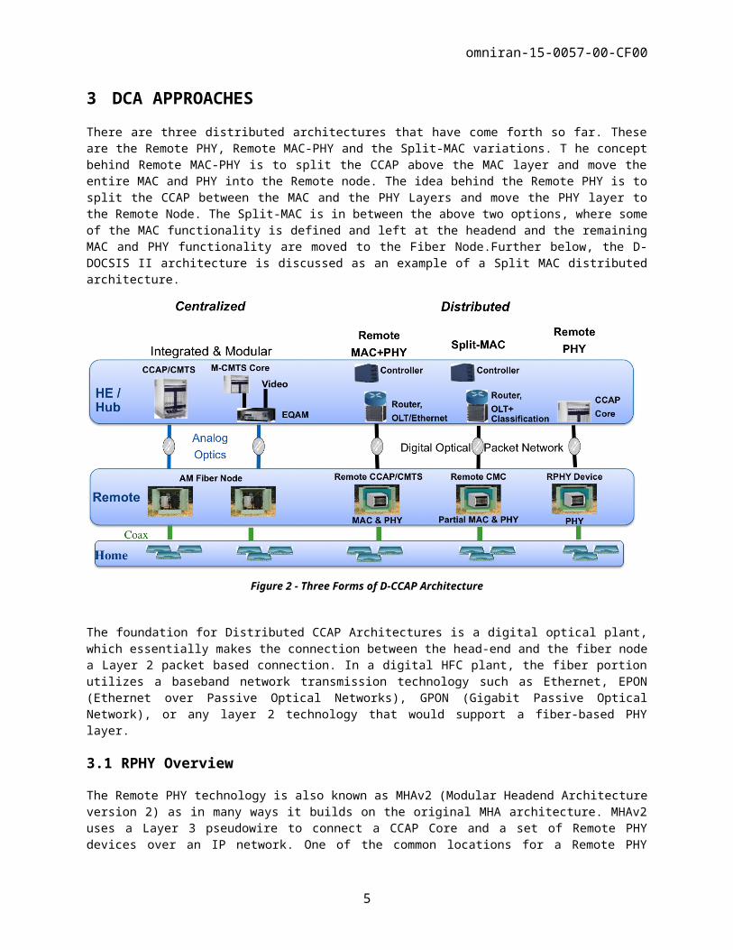
3 DCA APPROACHESThere are three distributed architectures that have come forth so far. These are the Remote PHY, Remote MAC-PHY and the Split-MAC variations. T he concept behind Remote MAC-PHY is to split the CCAP above the MAC layer and move the entire MAC and PHY into the Remote node. The idea behind the Remote PHY is to split the CCAP between the MAC and the PHY Layers and move the PHY layer to the Remote Node. The Split-MAC is in between the above two options, where some of the MAC functionality is defined and left at the headend and the remaining MAC and PHY functionality are moved to the Fiber Node.Further below, the D-DOCSIS II architecture is discussed as an example of a Split MAC distributed architecture.
Figure 2 - Three Forms of D-CCAP Architecture
The foundation for Distributed CCAP Architectures is a digital optical plant, which essentially makes the connection between the head-end and the fiber node a Layer 2 packet based connection. In a digital HFC plant, the fiber portion utilizes a baseband network transmission technology such as Ethernet, EPON (Ethernet over Passive Optical Networks), GPON (Gigabit Passive Optical Network), or any layer 2 technology that would support a fiber-based PHY layer.
3.1 RPHY Overview
The Remote PHY technology is also known as MHAv2 (Modular Headend Architecture version 2) as in many ways it builds on the original MHA architecture. MHAv2 uses a Layer 3 pseudowire to connect a CCAP Core and a set of Remote PHY devices over an IP network. One of the common locations for a Remote PHY device is the optical node device that is located at the junction of the fiber and coax plants.
In a Remote PHY System, the integrated CCAP is separated into two distinct components. The first component is the CCAP Core and the second component is the R-PHY Device (RPD).The CCAP Core contains both a CMTS Core for DOCSIS and an EQAM Core for Video.
5

omniran-15-0057-00-CF00
Figure 3 - Remote PHY High level Architecture
The CMTS Core contains the DOCSIS MAC and the upper layer DOCSIS protocols. This includes all signaling functions, downstream and upstream bandwidth scheduling, and DOCSIS framing. The DOCSIS functionality of the CMTS Core is defined by the existing DOCSIS Specifications. The EQAM Core contains all the video processing functions that an EQAM provides today.
The Remote PHY Device contains mainly PHY related circuitry, such as downstream QAM modulators, upstream QAM demodulators, together with pseudowire logic to connect to the CCAP Core. The RPD platform is a physical layer converter whose functions are:
To convert downstream DOCSIS, MPEG video and OOB signals received from a CCAP Core over a digital medium such as Ethernet or PON to analog for transmission over RF or linear optics.
To convert upstream DOCSIS and OOB signals received from an analog medium such as RF or linear optics to digital for transmission over Ethernet or PON to a CCAP Core.
3.2 RMACPHY Overview
The Remote MAC-PHY technology moves both the DOCSIS MAC and PHY layers down to the Remote/Fiber Node. The link between the Headend and the node is essentially a Layer 2 connection using Ethernet or various PON technology. There are two options for this, which are different based on how video is handled. In both cases the data forwarding CMTS functionality is at the remote node. A compact CMTS is deployed at the fiber node and the CMTS NSI connects through the digital optical network back to the cable headend. Based on where video EQAM functionality is placed, there are two options, as described below:
Remote CCAP
Remote CMTS + Divided EQAM.
Remote CCAP: The Remote CCAP term applies to an architecture where both the data and the video functions are moved to the Remote node. The CMTS functionality and the EQAM functionality are completely moved to the Fiber Node, and hence the term Remote CCAP. The video and data transit the L2 Ethernet link like any other IP traffic. The video and data need to be encrypted to protect from unauthorized access at the Remote node.
Figure 4 - Remote CCAP High level Architecture
6

omniran-15-0057-00-CF00
Remote CMTS + SplitEQAM: The Remote CMTS term applies to an architecture where only the data/CMTS functionality is moved into the remote node. The video/EQAM functionality is divided between the headend and the remote node, as in the Remote PHY architecture. The video MPEG packet processing is handled in the headend by an EQAM core device and the EQAM PHY inside the Remote CMTS handles the modulation of the video onto the wire.
Figure 5 - Remote CMTS + Split EQAM High level Architecture
7

omniran-15-0057-00-CF00
4 IEEE 802.1CF REFERENCE ARCHITECTURE
.
8