Introduction to Design for Sigma Developed By Toolkits/The DFSS... · OEM Bench Engineer, OEM ......
42
Tarek Lahdhiri, PhD, PE, PMP, BB-DFSS, SM-IEEE Introduction to Design for Sigma Developed By T. Lahdhiri, PhD, PE, PMP, BB-DFSS
-
Upload
nguyenngoc -
Category
Documents
-
view
218 -
download
0
Transcript of Introduction to Design for Sigma Developed By Toolkits/The DFSS... · OEM Bench Engineer, OEM ......

Tarek Lahdhiri, PhD, PE, PMP, BB-DFSS, SM-IEEE
Introduction to Design for Sigma
Developed By
T. Lahdhiri, PhD, PE, PMP, BB-DFSS
Tarek Lahdhiri, PhD, PE, PMP, BB-DFSS, SM-IEEE
Introduction Sigma and Design for Six Sigma
Tarek Lahdhiri, PhD, PE, PMP, BB-DFSS, SM-IEEE
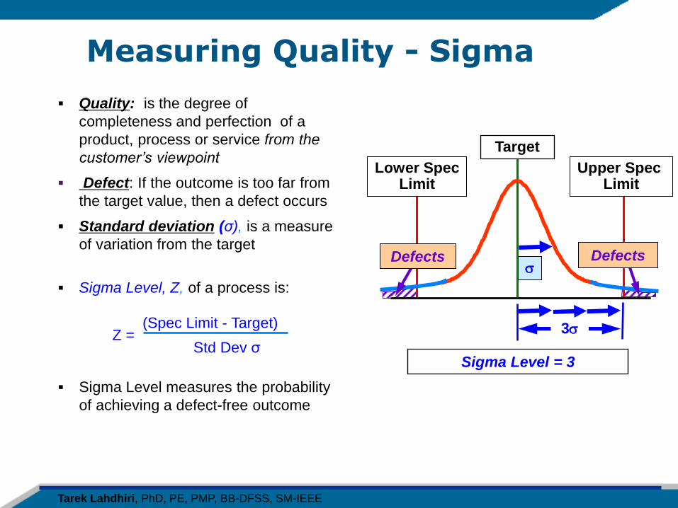
Measuring Quality - Sigma
Quality: is the degree of
completeness and perfection of a
product, process or service from the
customer’s viewpoint
Defect: If the outcome is too far from
the target value, then a defect occurs
Standard deviation (σ), is a measure
of variation from the target
Sigma Level, Z, of a process is:
(Spec Limit - Target) Z = Std Dev σ
Sigma Level measures the probability
of achieving a defect-free outcome
Target
Upper Spec Limit
Lower Spec Limit
s Defects Defects
3s
Sigma Level = 3
Tarek Lahdhiri, PhD, PE, PMP, BB-DFSS, SM-IEEE
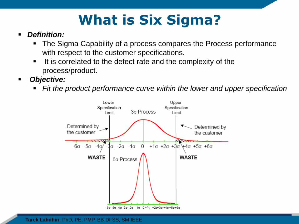
Definition:
The Sigma Capability of a process compares the Process performance
with respect to the customer specifications.
It is correlated to the defect rate and the complexity of the
process/product.
Objective:
Fit the product performance curve within the lower and upper specification
What is Six Sigma?
Tarek Lahdhiri, PhD, PE, PMP, BB-DFSS, SM-IEEE
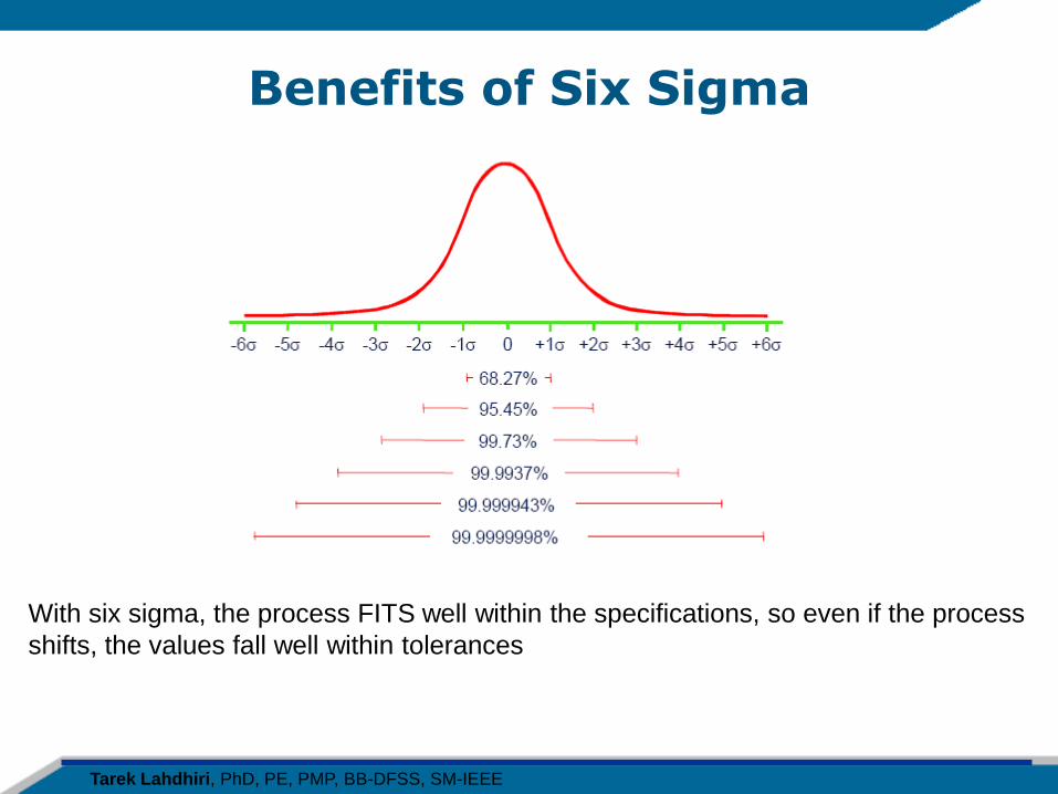
Benefits of Six Sigma
With six sigma, the process FITS well within the specifications, so even if the process
shifts, the values fall well within tolerances
Tarek Lahdhiri, PhD, PE, PMP, BB-DFSS, SM-IEEE
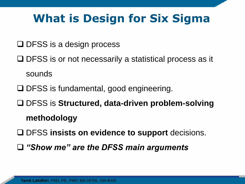
What is Design for Six Sigma
DFSS is a design process
DFSS is or not necessarily a statistical process as it
sounds
DFSS is fundamental, good engineering.
DFSS is Structured, data-driven problem-solving
methodology
DFSS insists on evidence to support decisions.
“Show me” are the DFSS main arguments
Tarek Lahdhiri, PhD, PE, PMP, BB-DFSS, SM-IEEE
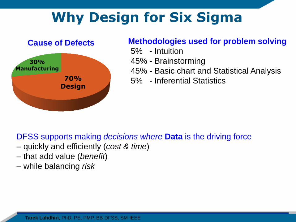
Why Design for Six Sigma
DFSS supports making decisions where Data is the driving force
– quickly and efficiently (cost & time)
– that add value (benefit)
– while balancing risk
Cause of Defects
30% Manufacturing
70% Design
Methodologies used for problem solving
5% - Intuition
45% - Brainstorming
45% - Basic chart and Statistical Analysis
5% - Inferential Statistics
Tarek Lahdhiri, PhD, PE, PMP, BB-DFSS, SM-IEEE
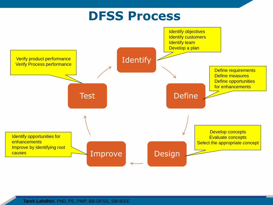
DFSS Process
Identify
Define
Design Improve
Test
Define requirements
Define measures
Define opportunities
for enhancements
Identify objectives
Identify customers
Identify team
Develop a plan
Develop concepts
Evaluate concepts
Select the appropriate concept
Verify product performance
Verify Process performance
Identify opportunities for
enhancements
Improve by identifying root
causes
Tarek Lahdhiri, PhD, PE, PMP, BB-DFSS, SM-IEEE
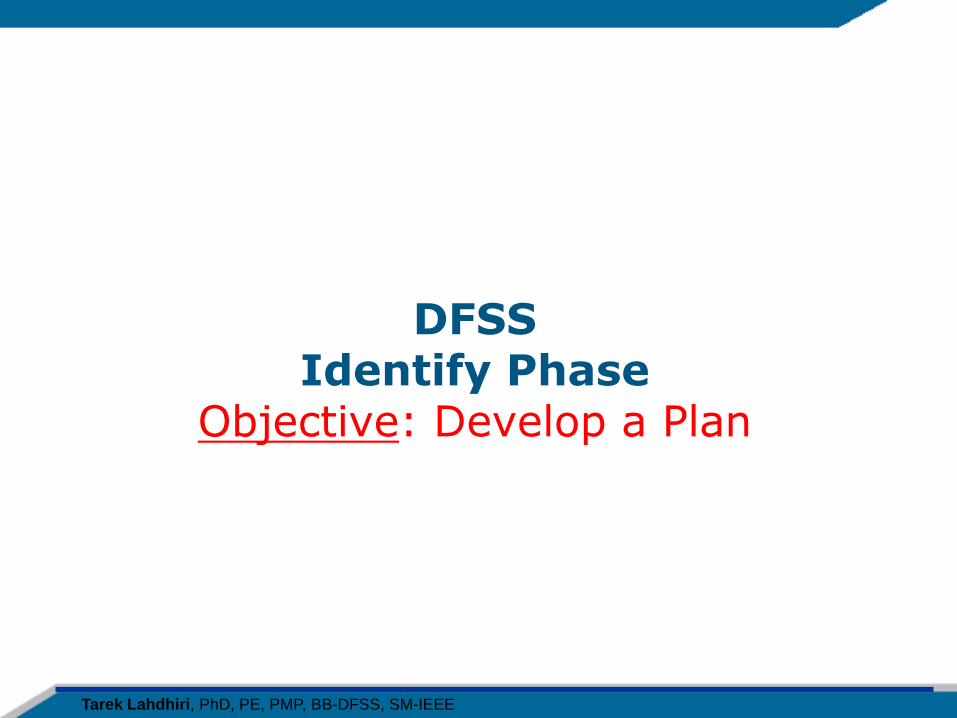
DFSS Identify Phase
Objective: Develop a Plan
Tarek Lahdhiri, PhD, PE, PMP, BB-DFSS, SM-IEEE
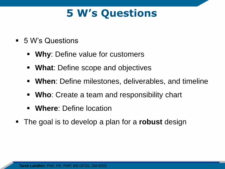
5 W’s Questions
5 W’s Questions
Why: Define value for customers
What: Define scope and objectives
When: Define milestones, deliverables, and timeline
Who: Create a team and responsibility chart
Where: Define location
The goal is to develop a plan for a robust design
Tarek Lahdhiri, PhD, PE, PMP, BB-DFSS, SM-IEEE
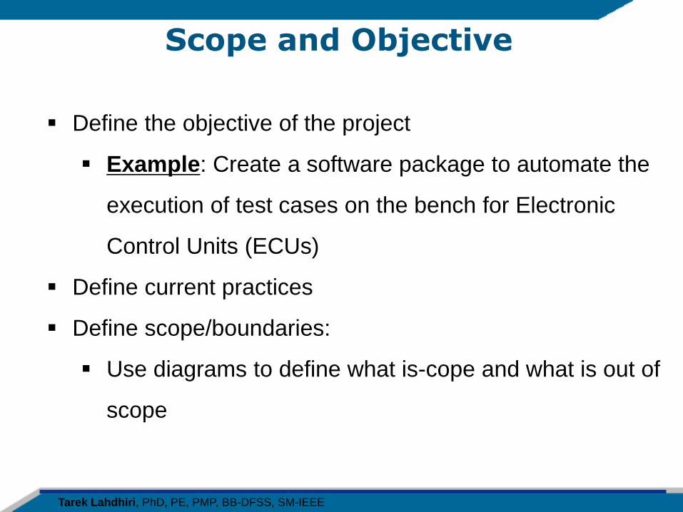
Scope and Objective
Define the objective of the project
Example: Create a software package to automate the
execution of test cases on the bench for Electronic
Control Units (ECUs)
Define current practices
Define scope/boundaries:
Use diagrams to define what is-cope and what is out of
scope
Tarek Lahdhiri, PhD, PE, PMP, BB-DFSS, SM-IEEE
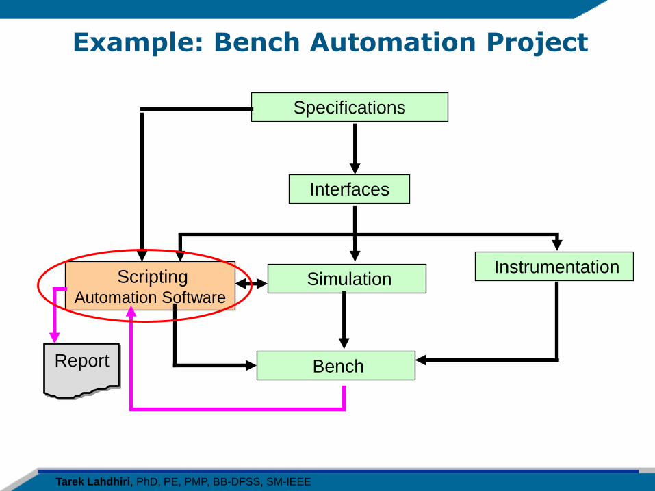
Example: Bench Automation Project
Specifications
Interfaces
Scripting Automation Software
Simulation Instrumentation
Bench Report
Tarek Lahdhiri, PhD, PE, PMP, BB-DFSS, SM-IEEE
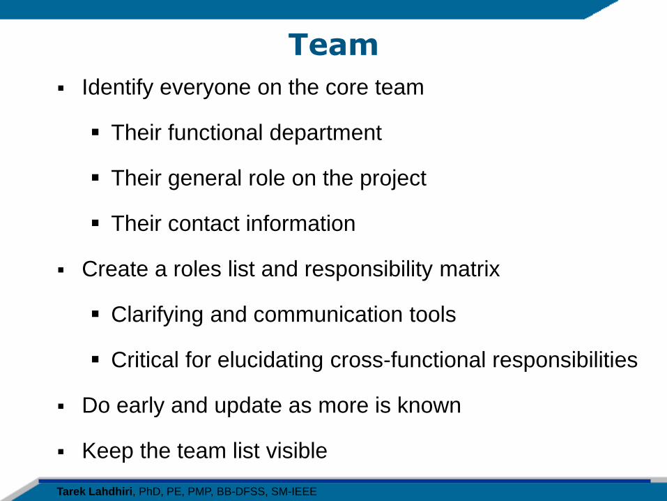
Team
Identify everyone on the core team
Their functional department
Their general role on the project
Their contact information
Create a roles list and responsibility matrix
Clarifying and communication tools
Critical for elucidating cross-functional responsibilities
Do early and update as more is known
Keep the team list visible
Tarek Lahdhiri, PhD, PE, PMP, BB-DFSS, SM-IEEE
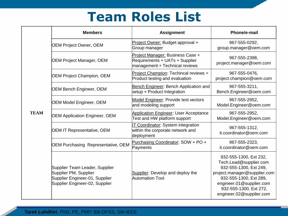
Team Roles List
TEAM
Members Assignment Phone/e-mail
OEM Project Owner, OEM Project Owner: Budget approval +
Group manager
967-555-0292,
OEM Project Manager, OEM
Project Manager: Business Case +
Requirements + UATs + Supplier
management + Technical reviews
967-555-2398,
OEM Project Champion, OEM Project Champion: Techincal reviews +
Product testing and evaluation
967-555-0476,
OEM Bench Engineer, OEM Bench Engineer: Bench Application and
setup + Product Integration
967-555-3211,
OEM Model Engineer, OEM Model Engineer: Provide test vectors
and modeling support
967-555-2952,
OEM Application Engineer, OEM Application Engineer: User Acceptance
Test and HW platform support
967-555-2952,
OEM IT Representative, OEM
IT Coordinator: System integration
within the corporate network and
deployment
967-555-1312,
OEM Purchasing Representative, OEM Purchasing Coordinator: SOW + PO +
Payments
967-555-2323,
Supplier Team Leader, Supplier
Supplier PM, Supplier
Supplier Engineer-01, Supplier
Supplier Engineer-02, Supplier
Supplier: Develop and deploy the
Automation Tool
932-555-1300, Ext 232,
932-555-1300, Ext 249,
932-555-1300, Ext 289,
932-555-1300, Ext 272,
Tarek Lahdhiri, PhD, PE, PMP, BB-DFSS, SM-IEEE
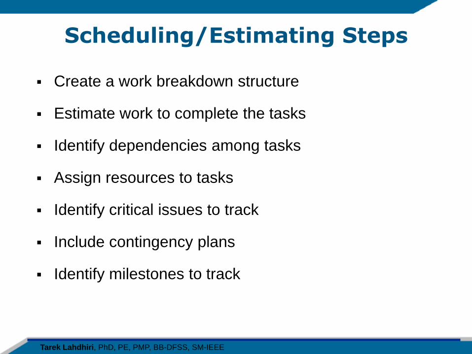
Scheduling/Estimating Steps
Create a work breakdown structure
Estimate work to complete the tasks
Identify dependencies among tasks
Assign resources to tasks
Identify critical issues to track
Include contingency plans
Identify milestones to track
Tarek Lahdhiri, PhD, PE, PMP, BB-DFSS, SM-IEEE
Project Timeline
Set up “tools” for tracking
Schedule software if desired
Project Vision
Milestone lists
Critical issues list
Action items, key decisions
Design review checklists
Testing and defect goals, tracking mechanisms
Keep these “tools” visible to the team
Tarek Lahdhiri, PhD, PE, PMP, BB-DFSS, SM-IEEE
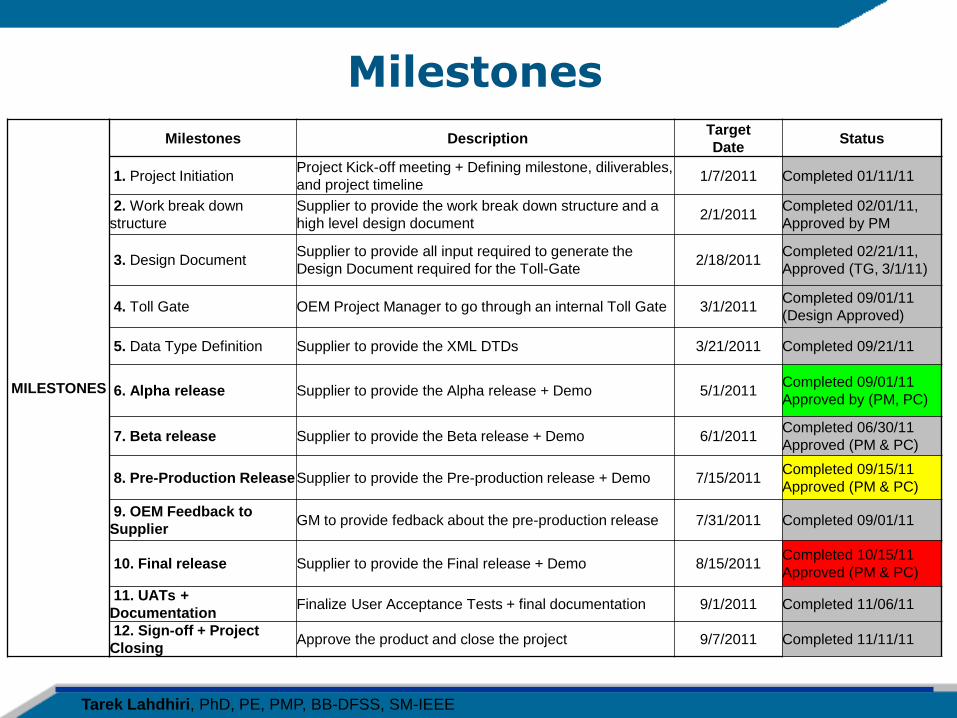
Milestones
MILESTONES
Milestones Description Target
Date Status
1. Project Initiation Project Kick-off meeting + Defining milestone, diliverables,
and project timeline 1/7/2011 Completed 01/11/11
2. Work break down
structure
Supplier to provide the work break down structure and a
high level design document 2/1/2011
Completed 02/01/11,
Approved by PM
3. Design Document Supplier to provide all input required to generate the
Design Document required for the Toll-Gate 2/18/2011
Completed 02/21/11,
Approved (TG, 3/1/11)
4. Toll Gate OEM Project Manager to go through an internal Toll Gate 3/1/2011 Completed 09/01/11
(Design Approved)
5. Data Type Definition Supplier to provide the XML DTDs 3/21/2011 Completed 09/21/11
6. Alpha release Supplier to provide the Alpha release + Demo 5/1/2011 Completed 09/01/11
Approved by (PM, PC)
7. Beta release Supplier to provide the Beta release + Demo 6/1/2011 Completed 06/30/11
Approved (PM & PC)
8. Pre-Production Release Supplier to provide the Pre-production release + Demo 7/15/2011 Completed 09/15/11
Approved (PM & PC)
9. OEM Feedback to
Supplier GM to provide fedback about the pre-production release 7/31/2011 Completed 09/01/11
10. Final release Supplier to provide the Final release + Demo 8/15/2011 Completed 10/15/11
Approved (PM & PC)
11. UATs +
Documentation Finalize User Acceptance Tests + final documentation 9/1/2011 Completed 11/06/11
12. Sign-off + Project
Closing Approve the product and close the project 9/7/2011 Completed 11/11/11
Tarek Lahdhiri, PhD, PE, PMP, BB-DFSS, SM-IEEE
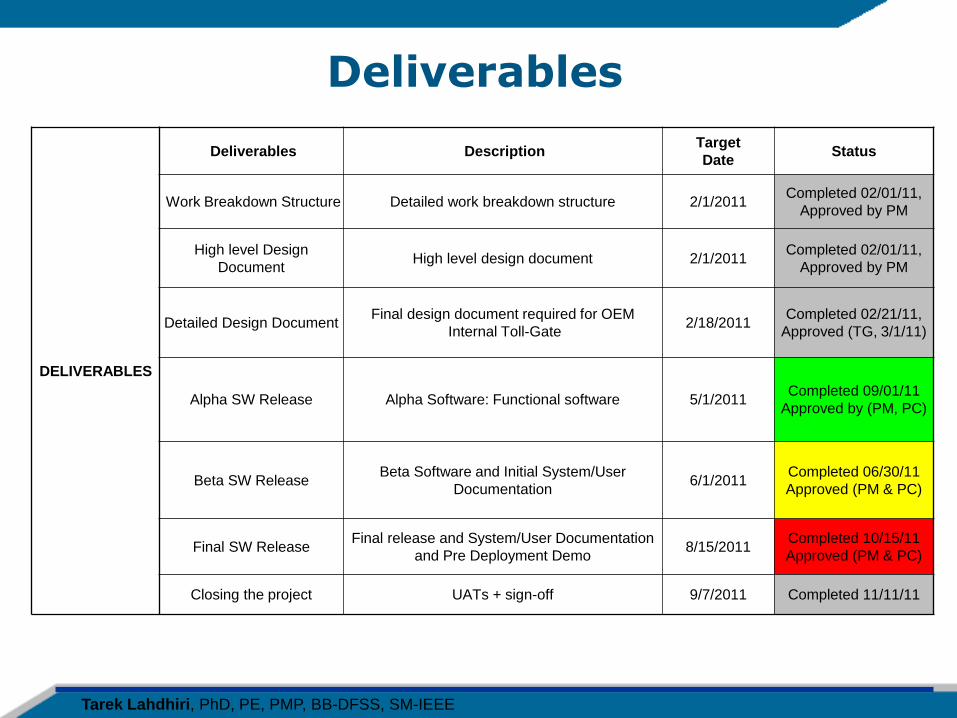
Deliverables
DELIVERABLES
Deliverables Description Target
Date Status
Work Breakdown Structure Detailed work breakdown structure 2/1/2011 Completed 02/01/11,
Approved by PM
High level Design
Document High level design document 2/1/2011
Completed 02/01/11,
Approved by PM
Detailed Design Document Final design document required for OEM
Internal Toll-Gate 2/18/2011
Completed 02/21/11,
Approved (TG, 3/1/11)
Alpha SW Release Alpha Software: Functional software 5/1/2011 Completed 09/01/11
Approved by (PM, PC)
Beta SW Release Beta Software and Initial System/User
Documentation 6/1/2011
Completed 06/30/11
Approved (PM & PC)
Final SW Release Final release and System/User Documentation
and Pre Deployment Demo 8/15/2011
Completed 10/15/11
Approved (PM & PC)
Closing the project UATs + sign-off 9/7/2011 Completed 11/11/11
Tarek Lahdhiri, PhD, PE, PMP, BB-DFSS, SM-IEEE
DFSS Define Phase
Objective: Define requirements
Tarek Lahdhiri, PhD, PE, PMP, BB-DFSS, SM-IEEE
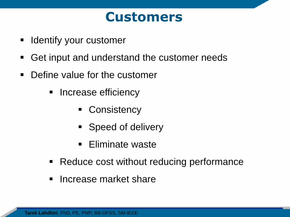
Customers
Identify your customer
Get input and understand the customer needs
Define value for the customer
Increase efficiency
Consistency
Speed of delivery
Eliminate waste
Reduce cost without reducing performance
Increase market share
Tarek Lahdhiri, PhD, PE, PMP, BB-DFSS, SM-IEEE
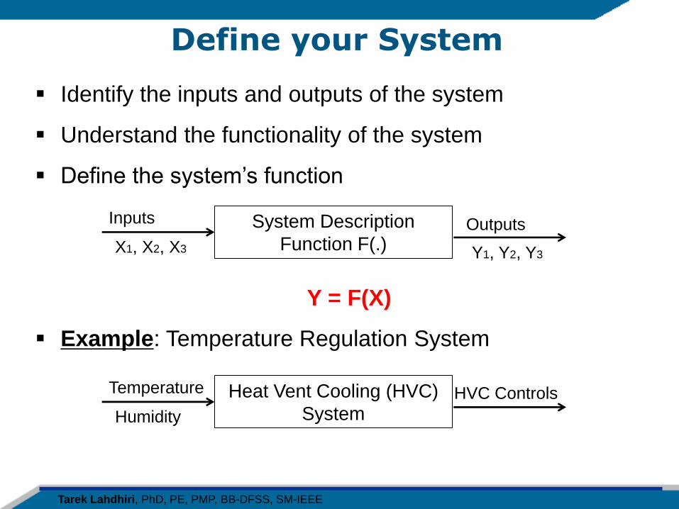
Define your System
Identify the inputs and outputs of the system
Understand the functionality of the system
Define the system’s function
Y = F(X)
Example: Temperature Regulation System
System Description
Function F(.)
Inputs
X1, X2, X3
Outputs
Heat Vent Cooling (HVC)
System
Temperature
Humidity
HVC Controls
Y1, Y2, Y3
Tarek Lahdhiri, PhD, PE, PMP, BB-DFSS, SM-IEEE
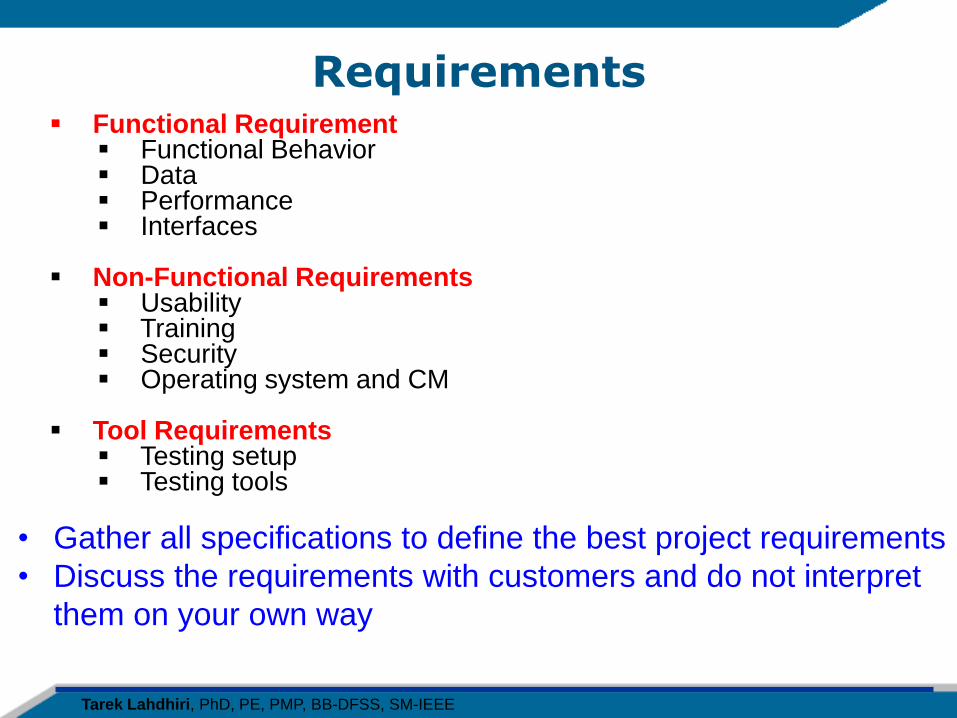
Requirements Functional Requirement
Functional Behavior Data Performance Interfaces
Non-Functional Requirements
Usability Training Security Operating system and CM
Tool Requirements
Testing setup Testing tools
• Gather all specifications to define the best project requirements
• Discuss the requirements with customers and do not interpret
them on your own way
Tarek Lahdhiri, PhD, PE, PMP, BB-DFSS, SM-IEEE
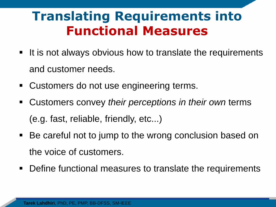
Translating Requirements into Functional Measures
It is not always obvious how to translate the requirements
and customer needs.
Customers do not use engineering terms.
Customers convey their perceptions in their own terms
(e.g. fast, reliable, friendly, etc...)
Be careful not to jump to the wrong conclusion based on
the voice of customers.
Define functional measures to translate the requirements
Tarek Lahdhiri, PhD, PE, PMP, BB-DFSS, SM-IEEE
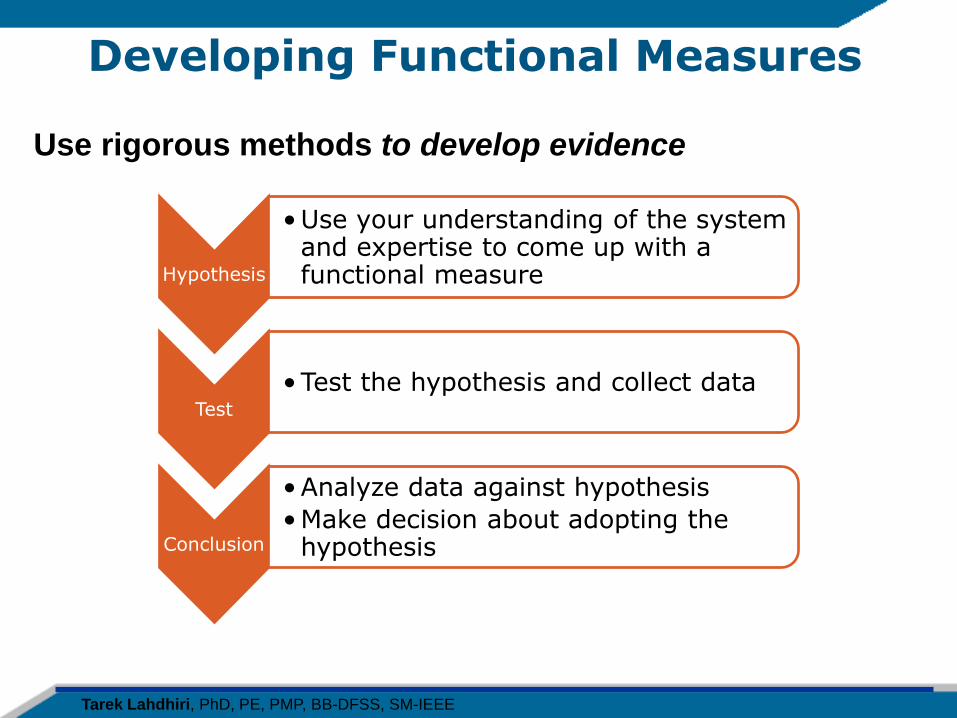
Developing Functional Measures
Use rigorous methods to develop evidence
Hypothesis
•Use your understanding of the system and expertise to come up with a functional measure
Test
•Test the hypothesis and collect data
Conclusion
•Analyze data against hypothesis
•Make decision about adopting the hypothesis
Tarek Lahdhiri, PhD, PE, PMP, BB-DFSS, SM-IEEE
DFSS Design Phase
Objective: Create the best concept
Tarek Lahdhiri, PhD, PE, PMP, BB-DFSS, SM-IEEE
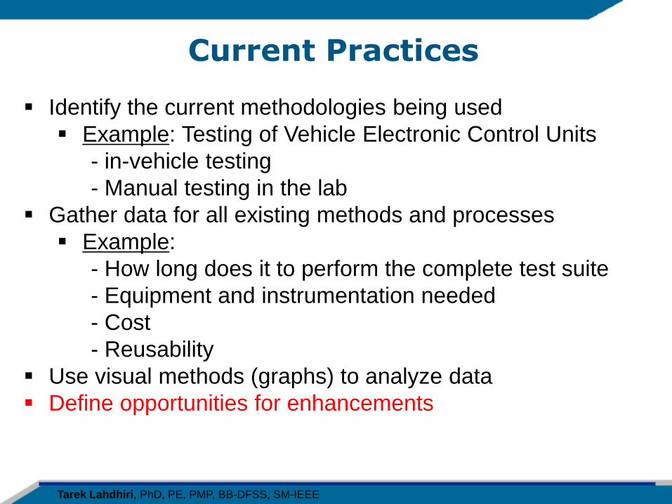
Current Practices
Identify the current methodologies being used
Example: Testing of Vehicle Electronic Control Units
- in-vehicle testing
- Manual testing in the lab
Gather data for all existing methods and processes
Example:
- How long does it to perform the complete test suite
- Equipment and instrumentation needed
- Cost
- Reusability
Use visual methods (graphs) to analyze data
Define opportunities for enhancements
Tarek Lahdhiri, PhD, PE, PMP, BB-DFSS, SM-IEEE
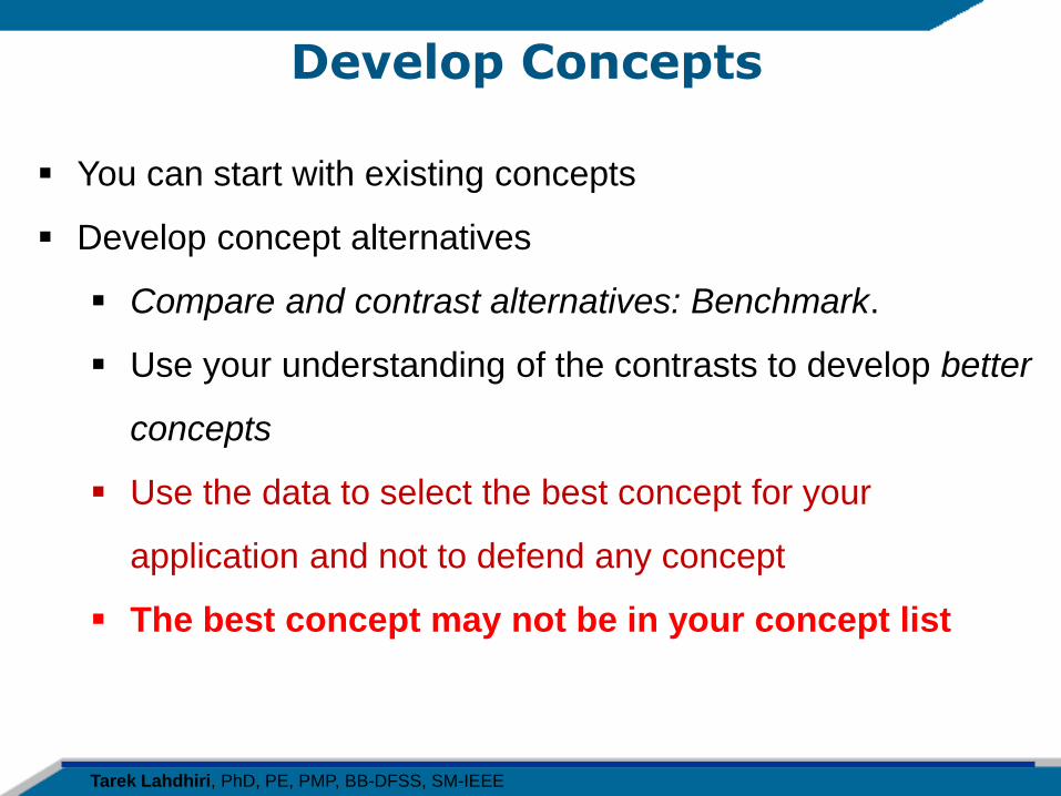
Develop Concepts
You can start with existing concepts
Develop concept alternatives
Compare and contrast alternatives: Benchmark.
Use your understanding of the contrasts to develop better
concepts
Use the data to select the best concept for your
application and not to defend any concept
The best concept may not be in your concept list
Tarek Lahdhiri, PhD, PE, PMP, BB-DFSS, SM-IEEE
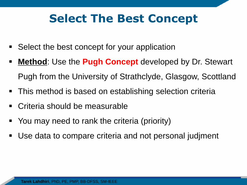
Select The Best Concept
Select the best concept for your application
Method: Use the Pugh Concept developed by Dr. Stewart
Pugh from the University of Strathclyde, Glasgow, Scottland
This method is based on establishing selection criteria
Criteria should be measurable
You may need to rank the criteria (priority)
Use data to compare criteria and not personal judjment
Tarek Lahdhiri, PhD, PE, PMP, BB-DFSS, SM-IEEE
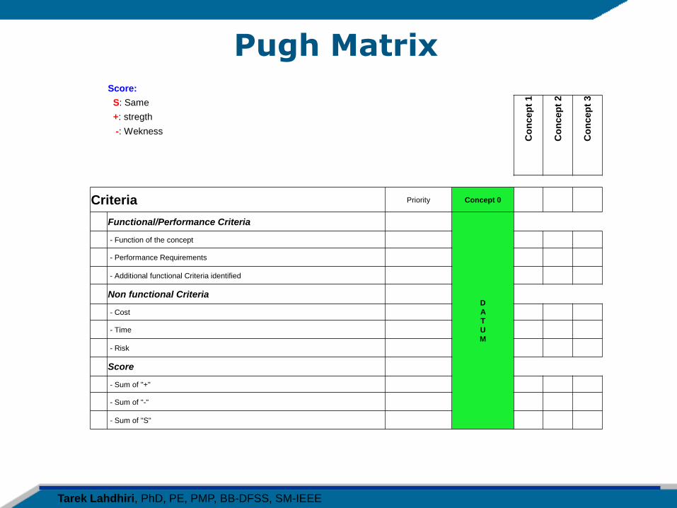
Pugh Matrix Score:
S: Same
Co
ncep
t 1
Co
nc
ep
t 2
Co
ncep
t 3
+: stregth
-: Wekness
Criteria Priority Concept 0
Functional/Performance Criteria
D
A
T
U
M
- Function of the concept
- Performance Requirements
- Additional functional Criteria identified
Non functional Criteria
- Cost
- Time
- Risk
Score
- Sum of "+"
- Sum of "-"
- Sum of "S"
Tarek Lahdhiri, PhD, PE, PMP, BB-DFSS, SM-IEEE
Sample of Pugh Matrix & Interpretation
Score:
S: Same
Co
ncep
t 1
Co
ncep
t 2
Co
ncep
t 3
+: stregth
-: Wekness
Criteria Priority Concept 0
Functional/Performance Criteria
D
A
T
U
M
- Function of the concept - S +
- Performance Requirements S S +
- Additional functional Criteria identified S S +
Non functional Criteria
- Cost + + S
- Time + S -
- Risk S S -
Score
- Sum of "+" 2 1 3
- Sum of "-" 1 0 2
- Sum of "S" 3 5 1
Less expensive and Fast
Does not add any value
to customer Less expensive
Does not add any value
to customer
Best for customer
Has risk and timing
issues
Best Solution:
Concept 4 = Hybrid of Concept 2 and 3
Tarek Lahdhiri, PhD, PE, PMP, BB-DFSS, SM-IEEE
DFSS Improve Phase
Objective: Optimize the Design and Improve the robustness
Tarek Lahdhiri, PhD, PE, PMP, BB-DFSS, SM-IEEE
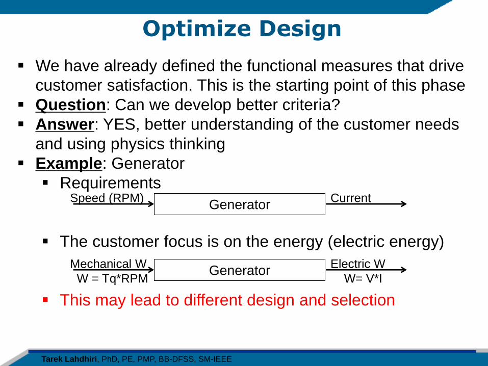
Optimize Design
We have already defined the functional measures that drive
customer satisfaction. This is the starting point of this phase
Question: Can we develop better criteria?
Answer: YES, better understanding of the customer needs
and using physics thinking
Example: Generator
Requirements
The customer focus is on the energy (electric energy)
This may lead to different design and selection
Generator Speed (RPM) Current
Generator Mechanical W
W = Tq*RPM
Electric W
W= V*I
Tarek Lahdhiri, PhD, PE, PMP, BB-DFSS, SM-IEEE
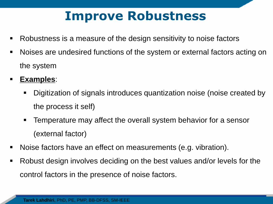
Improve Robustness
Robustness is a measure of the design sensitivity to noise factors
Noises are undesired functions of the system or external factors acting on
the system
Examples:
Digitization of signals introduces quantization noise (noise created by
the process it self)
Temperature may affect the overall system behavior for a sensor
(external factor)
Noise factors have an effect on measurements (e.g. vibration).
Robust design involves deciding on the best values and/or levels for the
control factors in the presence of noise factors.
Tarek Lahdhiri, PhD, PE, PMP, BB-DFSS, SM-IEEE
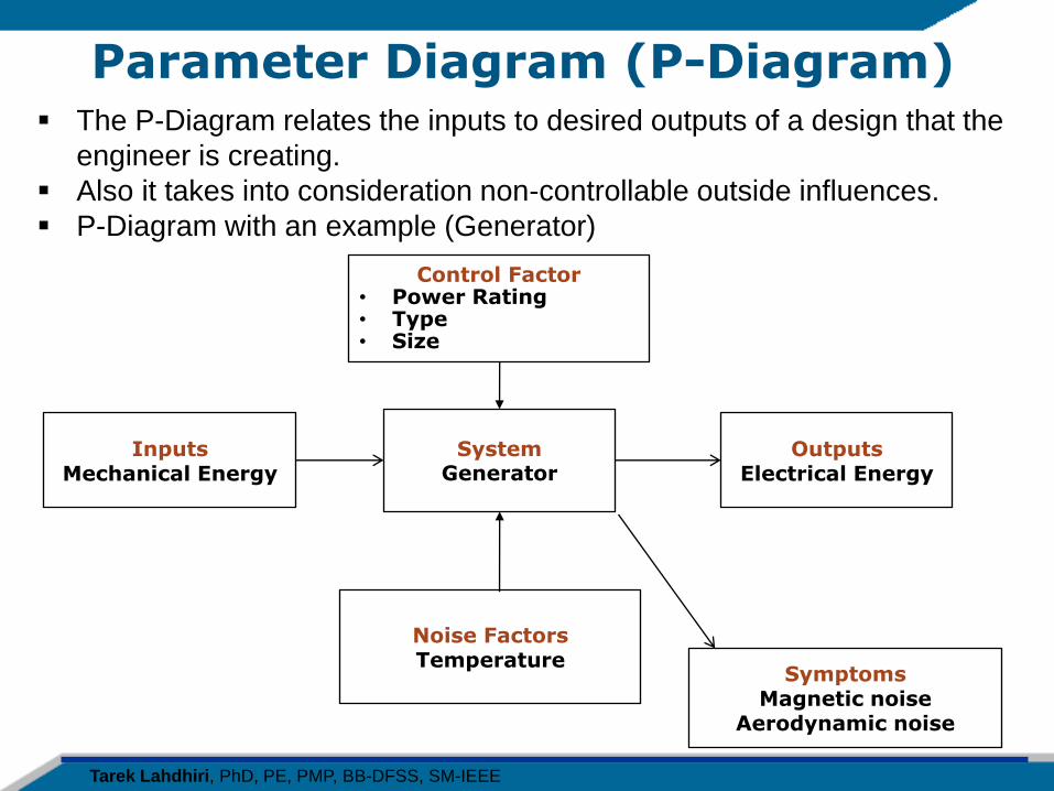
Parameter Diagram (P-Diagram) The P-Diagram relates the inputs to desired outputs of a design that the
engineer is creating.
Also it takes into consideration non-controllable outside influences.
P-Diagram with an example (Generator)
Control Factor • Power Rating • Type • Size
Outputs Electrical Energy
Noise Factors Temperature
System
Generator
Inputs Mechanical Energy
Symptoms Magnetic noise
Aerodynamic noise
Tarek Lahdhiri, PhD, PE, PMP, BB-DFSS, SM-IEEE
DFSS Test Phase
Objective: Verify that the design meets requirements
Tarek Lahdhiri, PhD, PE, PMP, BB-DFSS, SM-IEEE
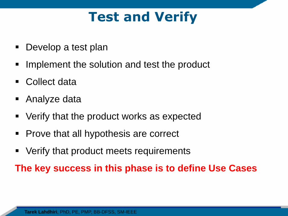
Test and Verify
Develop a test plan
Implement the solution and test the product
Collect data
Analyze data
Verify that the product works as expected
Prove that all hypothesis are correct
Verify that product meets requirements
The key success in this phase is to define Use Cases
Tarek Lahdhiri, PhD, PE, PMP, BB-DFSS, SM-IEEE
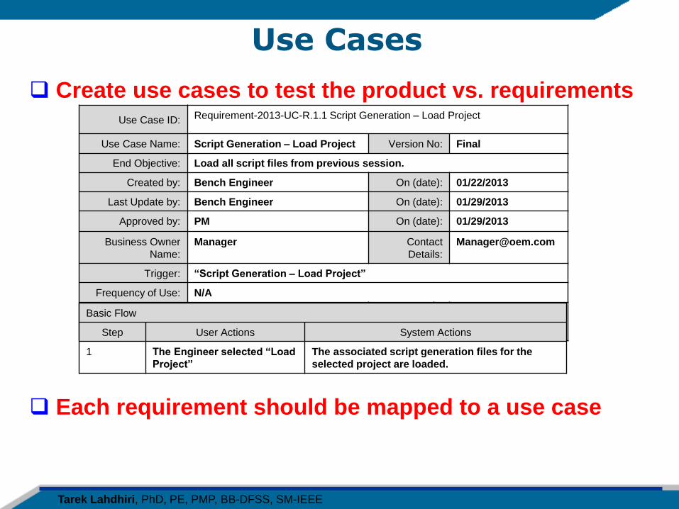
Use Cases
Create use cases to test the product vs. requirements
Use Case ID: Requirement-2013-UC-R.1.1 Script Generation – Load Project
Use Case Name: Script Generation – Load Project Version No: Final
End Objective: Load all script files from previous session.
Created by: Bench Engineer On (date): 01/22/2013
Last Update by: Bench Engineer On (date): 01/29/2013
Approved by: PM On (date): 01/29/2013
Business Owner
Name:
Manager Contact
Details:
Trigger: “Script Generation – Load Project”
Frequency of Use: N/A
Basic Flow
Step User Actions System Actions
1 The Engineer selected “Load
Project”
The associated script generation files for the
selected project are loaded.
Each requirement should be mapped to a use case
Tarek Lahdhiri, PhD, PE, PMP, BB-DFSS, SM-IEEE
DFSS Closing and Concluding Remarks
Tarek Lahdhiri, PhD, PE, PMP, BB-DFSS, SM-IEEE
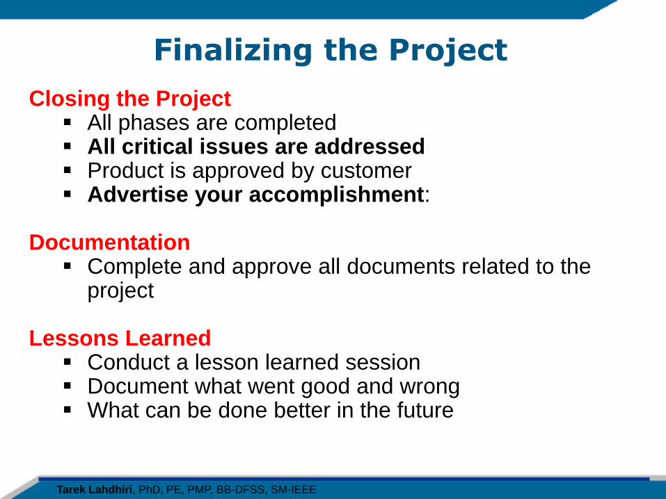
Finalizing the Project
Closing the Project All phases are completed All critical issues are addressed Product is approved by customer Advertise your accomplishment:
Documentation Complete and approve all documents related to the
project Lessons Learned
Conduct a lesson learned session Document what went good and wrong What can be done better in the future
Tarek Lahdhiri, PhD, PE, PMP, BB-DFSS, SM-IEEE
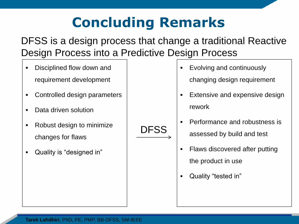
Concluding Remarks
Evolving and continuously
changing design requirement
Extensive and expensive design
rework
Performance and robustness is
assessed by build and test
Flaws discovered after putting
the product in use
Quality “tested in”
DFSS is a design process that change a traditional Reactive
Design Process into a Predictive Design Process
Disciplined flow down and
requirement development
Controlled design parameters
Data driven solution
Robust design to minimize
changes for flaws
Quality is “designed in”
DFSS

Tarek Lahdhiri, PhD, PE, PMP, BB-DFSS, SM-IEEE
IT’S TIME FOR QUESTIONS
Tarek Lahdhiri, PhD, PE, PMP, BB-DFSS, SM-IEEE
Thank you for your time.
Contact Information: Tarek Lahdhiri
Email: [email protected]