Computer Networks Performance Metrics Advanced Computer Networks Fall 2013.

Spring 2003 UCSC CMPE150 1
CMPE 150: Introduction to
Computer Networks
FINAL REVIEW
Venkatesh Rajendran

Spring 2003 UCSC CMPE150 2
Class Final Exam
Final examThree hours40 – 50 questions -- comprehensiveMultiple choice as the midtermScantron – bring your sheet and pencils
Wednesday – June 11th 8:00 – 11:00amSix short days.. Tick, tick, tick…

Spring 2003 UCSC CMPE150 3
Principles of Computer Communication
Protocol specification: The description of the protocol is complete and accurate.Safety: A protocol does what it is supposed to do, all the time.Liveness: A protocol does not leave any deadlocks.Efficiency: A protocol makes efficient use of available resources.Fairness: Fair or contractual use of resources Simplicity is desirable, but not necessary.

Spring 2003 UCSC CMPE150 4
Layering ModelPurpose is to divide and conquer complex software and hardware needed to implement servicesPartition services and functions needed in system into layersEach layer of service is provided by peer protocol entitiesCommunication can be point-to-point or multipoint
Layer N packetsNODE BNODE A Layer-N
Protocol EntityLayer-N
Protocol Entity(virtual communication)protocol
Layer-(N - 1)Protocol Entity
interface
Layer-(N - 1) Protocol Entity

Spring 2003 UCSC CMPE150 5
Protocol Correctness
A protocol must be safe and liveSafety:
Protocol provides the desired service all the time
Liveness:Protocol has no deadlocks (no process waits forever for an event to occur)
Proving one may depend on the other

Spring 2003 UCSC CMPE150 6
Protocol PerformanceAverage delay
Time between transmission of an information bit and reception of the bit at the receiver
Throughput or capacityNumber of information bits sent divided by the time between transmission of first bit and delivery of the last bit
Computations will make strong assumptions; in most cases, results of analytical model provide only a rough approximationMost effective for comparative analysis

Spring 2003 UCSC CMPE150 7
Basic Network Services
1
1 1
1
2 2 2
1,2 1,2S D
Data may take different paths to destination
Connection-oriented service: Reliable data transfer: In-order delivery, no duplicates or missing data.Flow control: Do not congest the receiver(s).Congestion control: Do not congest the network(s).
Shared network resources

Spring 2003 UCSC CMPE150 8
Basic Network Services1,2,3 2,1,3S D
Shared network resources
Connectionless service:No delivery guarantees needed from the network.Any connection-oriented service to application is provided by end-to-end protocol.

Spring 2003 UCSC CMPE150 9
Circuit Switching
Portion of physical resource is assigned to a single connection.Delay and signaling overhead in establishing and ending connections.
DATA
S D
call request
call accept
termination ackcall termination

Spring 2003 UCSC CMPE150 10
Message Switching
Message from sender is sent on a store-and-forward basis.Message has a header used for forwarding.Resources shared among different calls.
message
DS
Spring 2003 UCSC CMPE150 11
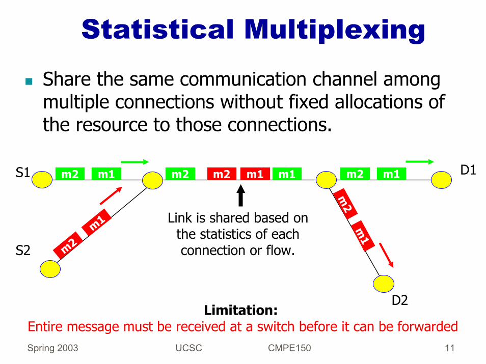
Statistical Multiplexing
Share the same communication channel among multiple connections without fixed allocations of the resource to those connections.
S1 D1
S2
D2
m2 m1
m2m1
m2 m1m1m2 m2 m1
m2
m1
Link is shared based on the statistics of each connection or flow.
Limitation:Entire message must be received at a switch before it can be forwarded

Spring 2003 UCSC CMPE150 12
Packet Switching
Resources are shared among connections Packets from the same connection can be processed concurrently
Connection setup delay can be avoided using datagrams
packet 1
packet 4
packet 2
packet 3
DS
Spring 2003 UCSC CMPE150 13
Packet SwitchingInformation is organized into packetsA packet consists of a header and a payloadHeader specifies the control information needed to transport the packet from origin to destinationPackets are forwarded from source to destination using routing tablesThere are two basic approaches to packet switching:
datagramsvirtual circuits

Spring 2003 UCSC CMPE150 14
Datagrams
Routing table specifies next hop to each destinationPackets are forwarded based on the routing tableEach packet is routed independently
To b go to 2 nextTo d go to 3 nextTo e go to 2 nextTo 4 go to 3 next….
d
b5
4
6
a
c3
1
2
7
e
a->b
a->ba->b
c->d
c->da->
e
a->ea->e
a->e

Spring 2003 UCSC CMPE150 15
Virtual CircuitsVC1
VC2
VC3
d
b5
4
6
a
c3
1
2
7
e
Virtual circuits are established and terminated much like circuits in circuit switching.Statistical multiplexing using packets, rather than FDM or TDM is used to share links among connections.

Spring 2003 UCSC CMPE150 16
Transmission Media
We consider the physical layer as a “black box”We are interested in the characteristics andservices provided by the transmission media that impact the link layer and higher layers.Parameters:
BandwidthDelay or latency: average and variance (aka jitter)Storage capacity (bandwidth-delay product)Reliability and securityOrder of deliveryType of sharing or access

Spring 2003 UCSC CMPE150 17
BandwidthWe think of the bandwidth of a network or link as
the number of information bits that can be transmitted over it in a certain period of time (e.g., bits per second).
The bandwidth of a link is really the frequency range tolerated by the channel without major attenuation.
Telephone line is 3000 Hz (300Hz to 3300 Hz)
Available bandwidth depends on the rate at which channel can change stored energy.We can model waveforms as sums of sine waves of different frequencies.Channel attenuates and delays each frequency component differently, causing distortion.

Spring 2003 UCSC CMPE150 18
Sources of Packet Delay
A Btransmission time of packet
over each link
propagation delayof each link
nodalprocessing
nodalprocessing
queueing delay
queueing delay
Spring 2003 UCSC CMPE150 19
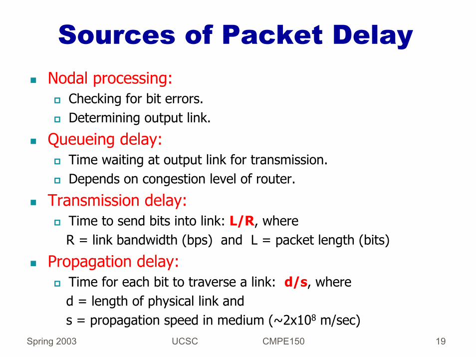
Sources of Packet DelayNodal processing:
Checking for bit errors.Determining output link.
Queueing delay:Time waiting at output link for transmission. Depends on congestion level of router.
Transmission delay:Time to send bits into link: L/R, whereR = link bandwidth (bps) and L = packet length (bits)
Propagation delay:Time for each bit to traverse a link: d/s, whered = length of physical link and s = propagation speed in medium (~2x10⁸ m/sec)

Spring 2003 UCSC CMPE150 20
Bandwidth-Delay ProductThe amount of data “stored” in the link.Think of a link as a pipe; the latency is the length of the pipe and the bandwidth is its diameter. The BD product gives the volume of the pipe.Example: A channel of 50 ms latency and just 45 Mbps bandwidth can hold 2.25 million bits (the same as the memory of a PC of early 80s!).We are moving to Gigabit networks...Big bandwidth and big distances require:
Big aggregation and big memories at hostsNew reliable transmission algorithmsMigration from client-server to client-content models.

Spring 2003 UCSC CMPE150 21
Other Parameters
Reliability: We will assume that information is transmitted correctly across a link or network with a given likelihood.Security: We will likely not cover this aspect in much detail :(Order of delivery: We will assume FIFO and non-FIFO delivery of packets or messages, depending on the protocol and transmission media.Access: We will consider point-to-point and broadcast links.

Spring 2003 UCSC CMPE150 22
Functions at The Link LayerMAC: (Medium Access Control)
Framing and synchronizationError checkingNaming within LANs (with MAC addresses)Sharing of mediumFlow control (in some cases)
LLC: (Logical Link Control)Retransmission strategyLink management (deciding when a link exists or does not)Flow control (in some cases)

Spring 2003 UCSC CMPE150 23
Framing of BitsThe objective is for the receiver to understand the packets (frames) sent by the sender when bits may get corrupted over the channel.Three approaches:
Character- or byte-oriented framing: BISYNC, IMP-IMP, SLIP, and PPPBit-oriented framing: HDLCClock-based framing: SONET

Spring 2003 UCSC CMPE150 24
Character-Oriented FramingA frame starts and ends with a predefined sequence of control bytes or characters, and the occurrence of such sequence in the packetpayload is avoided by byte stuffing.Consider the ARPANET IMP-IMP protocol:
SYN
DLE
STX packet payload (header and data)
CR
C
CR
C
CR
C
ETX
DLE
SYN
SYN = synchronizationDLE = data link escapeSTX = packet start
Character stuffing:If DLE occurs in packet data, sender substitutes DLE with DLE DLEReceiver substitutes DLE DLE in packet payload with DLE In PPP, flag is 01111110 and such pattern in payload is preceded by 01111101
Read Section 5.8 in textbook summarizing PPP

Spring 2003 UCSC CMPE150 25
Bit-Oriented FramingThe same procedure is used with bits, bits are stuffed to break the occurrence of control flags.Bit stuffing consists of adding a bit after the occurrence of a bit pattern equal to the control flag used to frame the packet.Assume the control flag is 01111110If flag pattern occurs in payload, sender must transmit something different and receiver must be able to get original data.HOW?...Sender inserts a 0 after 5 1’s, and receiver deletes any 0 received after five 1’s in a bit sequence, and the frame is ended if after 5 1’s “10” is detected.
Original data: …..1011010100111111011000101111110011….
01111110 01111110
flag flag
…..101101010011111010 110001011111010011….
payload with bit stuffing
Receiver then deletes stuffed 0 in any sequence ...1111101 and obtains original data: …..1011010100111111011000101111110011….

Spring 2003 UCSC CMPE150 26
CRCCRC codes detect errors by adding a few bits (redundancy bits or CRC bits) to each packet.The attractive features of CRC are that only a few redundancy bits are needed to protect many bits of information, and it can be implemented with very simple hardware.A message of m bits is transmitted with r redundancy bits as a transmitted string T = M.RWith the message bits being the most significant bits transmitted, and given that R occupies r bit positions, we have
M R
r+m-1 r r-1 0 bits
RMT r +⋅≡ 2

Spring 2003 UCSC CMPE150 27
CRCThe procedure to choose R to protect M is remarkably simple.A string G of r+1 bits called the generator is agreed upon.R is chosen so that T = A xG for some A
=> If the received string T’ is not a multiple of G, then an error has been detected!T’ equals the (modulo 2) addition of T and an error pattern E, such that a 0 in the pattern indicates no error in that bit position.Now we have:
ER2' 2
e, therefor;2
++⋅≡
+×=⋅
×=+⋅≡
r
r
r
MTalsoRGAMGARMT
R is the remainder of dividing by G theshifted M

Spring 2003 UCSC CMPE150 28
CRCTherefore, to protect M, the sender:
Computes R by dividing M (shifted r bit positions) by GTransmits M . R
When the receiver obtains T’ :It divides T’ by GDecides that there is an error if the remainder of the division is not 0
The trick is then choosing a G for which the likelihood that T’ contains an error string E that is divisible by G is very small.

Spring 2003 UCSC CMPE150 29
Contention-Based MAC Protocols
No coordination: Stations transmit at will when they have data to send (e.g., ALOHA)Carrier sensing (listen before transmit): Stations sense the channel before transmitting a data packet (e.g., CSMA).Listen before and during transmission: Stations listen before transmitting and stop if noise is heard while transmitting (CSMA/CD).Collision avoidance (floor acquisition): Stations carry out a handshake to determine which one can send a data packet (e.g., MACA, FAMA, IEEE802.11, RIMA).Collision resolution: Stations determine which one should try again after a collision.

Spring 2003 UCSC CMPE150 30
ALOHA ProtocolThe first protocol for multiple access channels; the first analysis of such protocols (Norm Abramson, Univ. of Hawaii, 1970).Originally planned for systems with a central base station or a satellite transponder.
Two frequency bands;Up link and down link(413MHz, 407MH at 9600bps)
Central node retransmitsevery packet it receives!

Spring 2003 UCSC CMPE150 31
ALOHA Protocol
Population is a large number of bursty stations.Each station transmits a packet whenever it receives it from its user; no coordination with other stations!Central node retransmits all packets (good or bad) on down link.Stations decide to retransmit based on the information they hear from central node

Spring 2003 UCSC CMPE150 32
Throughput of ALOHA Protocol
time
node i frame
interfering frame
interfering frame
packet overlaps with start of packet
from node i
packet overlaps with end of packet
from node i
t0t0 - 1 t0 + 1
N nodes in the system
The probability of a station starting a packet in a given time slot is p.Node i transmits in time slot starting at t0, i.e., time slot 2.The packet from node i is successful if no other station transmits in the time slots 1 and 2.

Spring 2003 UCSC CMPE150 33
Throughput of ALOHA Protocol
time
node i frame
t0
packet overlaps with start of packet
from node i
t0 - 1 t0 + 1
packet overlaps with end of packet
from node i
interfering frame
interfering frame
Node i’s frame is vulnerable from any arrival in the time interval
(t0-1, t0+1]
Highest throughput when we have one packet for each 2-packet time period

Spring 2003 UCSC CMPE150 34
Slotted ALOHAThe throughput of ALOHA can be improved by reducing the time a packet is vulnerable to interference from other packets.Slotted ALOHA works in a “slotted channel” providing discrete time slots.Stations can start transmitting only at the beginning of time slots.The time synchronization needed for slotting is accomplished at the physical layer, and some synchronization is required in many cases anyway.

Spring 2003 UCSC CMPE150 35
Throughput of Slotted ALOHA
The vulnerability period of a packet is a slot time:
time
arrivals
i Any arrivals in prior slotcollide with packet i
We double the capacity of the channel (to about 36%)because
we reduce in half the vulnerability period of a packet.

Spring 2003 UCSC CMPE150 36
CSMA: Carrier Sense Multiple Access
The capacity of ALOHA or slotted ALOHA is limited by the large vulnerability period of a packet.By listening before transmitting, stations try to reduce the vulnerability period to one propagation delay.This is the basis of CSMA (Kleinrock and Tobagi, UCLA, 1975)Same assumptions made for ALOHA are made now for CSMA.

Spring 2003 UCSC CMPE150 37
CSMA ProtocolAssume non-persistent carrier sensing.Requires a maximum propagation delay much smaller than packet lengths!
transmit
no
wait for a round-trip time
positiveack?yes
compute randombackoff integer kno
delay packettransmission
k times
Packetready
ChannelBusy?
yes

Spring 2003 UCSC CMPE150 38
CSMA ThroughputBecause prop. delay is much smaller than packet length, slotted and pure CSMA have very similar performance.When MAC protocol requires small prop delays, we can use slotted version to predict performance of unslotted version.
10-3 10 -2 10 -1 10 0 101 10 2 103 104 1050
0.1
0.2
0.3
0.4
0.5
0.6
0.7
0.8
0.9
1Analytical Results
Offered Load: G
S (T
hrou
ghpu
t)
Pure CSMA
Slotted CSMA
Pure Aloha
Slotted Aloha
Reminder: These results are only an upper bound on performance, because we did not take into account the effect of ACKs sent from receivers!

Spring 2003 UCSC CMPE150 39
CSMA/CD:CSMA with Collision Detection
CSMA improves on the performance of ALOHA tremendously.The remaining limitation is that, once a packet is sent, feedback occurs a roundtrip time after the entire packet is transmitted.The solution to improve on the performance of CSMA is to listen to the channel while a packet is being sent.This is called collision detection.R.M Metcalfe and D.R. Boggs, “Ethernet: Distributed Packet Switching for Local Computer Networks,” Comm. ACM, Vol. 19, 1976 (Xerox PARC).
Spring 2003 UCSC CMPE150 40
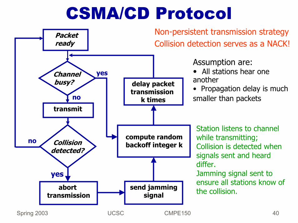
CSMA/CD ProtocolNon-persistent transmission strategyCollision detection serves as a NACK!
transmit
no
abort transmission
Collision detected?
no compute randombackoff integer k
yes
delay packettransmission
k times
Packetready
Channelbusy?
yes
send jammingsignal
Assumption are:• All stations hear one another • Propagation delay is much smaller than packets
Station listens to channel while transmitting; Collision is detected when signals sent and heard differ.Jamming signal sent to ensure all stations know of the collision.

Spring 2003 UCSC CMPE150 41
CSMA/CD collision detection

Spring 2003 UCSC CMPE150 42
Persistence after Carrier Sensing
After detecting carrier, a station can persist trying to transmit after the channel is idle again.Persistence can be done with some probability; in which case we have a p-persistent strategy (Ethernet uses a 1-persistent strategy)Persistence can be limited, in which case a station persists trying to transmit only if the channel becomes idle within a given timeout that is much smaller than the duration of a data packet.Can you think why these approaches are desirable?……

Spring 2003 UCSC CMPE150 43
Collision AvoidanceCollision avoidance emulates collision detection in networks where stations are half duplex.First protocol was proposed by Kleinrock and Tobagi (Split Reservation Multiple Access).Many protocols have been proposed since then: MACA, MACAW, FAMA, RIMA.The objective of collision avoidance protocols is to eliminate the hidden-terminal problem of CSMA:
S, R, and N hear one another, and R, N, and H hear one another
S
N
R
H N hears S’s transmission
However, S and H cannot hear each other’s transmissions to R, and cause interference at the receiver R.

Spring 2003 UCSC CMPE150 44
Collision AvoidanceBecause of hidden terminals, the vulnerability of a data packet is just as in pure ALOHA, twice its length.With collision avoidance, stations exchange small control packets to determine which sender can transmit to a receiver.The collision avoidance dialogue can be controlled by the sender or the receiver.In sender-initiated collision avoidance we have:RTS (S to R) -> CTS (R to S) -> DATA (S to R) -> ACK (R to S)
In receiver-initiated collision avoidance we can have:RTR (R to S) -> DATA (S to R) -> ACK (R to S)

Spring 2003 UCSC CMPE150 45
Example of CSMA/CA: Floor Acquisition Multiple AccessStations use carrier sensing to send any packet.The CTS lasts much longer than an RTS (CTS Dominance) to force the interfering sources to detect carrier (from the receiver) and back off.
timeRTS
S to R
CTSR to S
RTS
τ2noise is heardH to R
RTS from S arrives at R with no collisions.RTS from H must start within one prop. delay from CTS from R to S.H must hear noise from CTS and backs off!
S R HRTS
CTS CTS
RTS

Spring 2003 UCSC CMPE150 46
Collision Resolution and Backoff Strategies
Used to stabilize the system by preventing traffic loads that exceed its capacity.Collision resolution: Let packet that collide resolve when each is transmitted and block new traffic from entering the system.Backoff strategies: Increase the time between retransmissions when traffic load (that creates collisions) increases.

Spring 2003 UCSC CMPE150 47
Collision Resolution and Backoff Strategies
Backoff strategy in Ethernet: After experiencing the nth collision of a frame, pick a value, K, randomly from the set {0, 1, 2,…, 2^m -1} with m= min{n, 10}.Wait K * 512 bit times before attempting a retransmission.
Goal is to reduce offered load to the channel; however, it provides no assurance that a retransmission will be sent ahead of another new transmission from other nodes.

Spring 2003 UCSC CMPE150 48
TDMA
TDMA: time division multiple accessaccess to channel in "rounds" each station gets fixed length slot (length = pkt trans time) in each round unused slots go idle example: 6-station LAN, 1,3,4 have pkt, slots 2,5,6 idle

Spring 2003 UCSC CMPE150 49
FDMAFDMA: frequency division multiple access
channel spectrum divided into frequency bandseach station assigned fixed frequency bandunused transmission time in frequency bands go idle example: 6-station LAN, 1,3,4 have pkt, frequency bands 2,5,6 idle.
freq
uenc
y ba
nds
time

Spring 2003 UCSC CMPE150 50
Channel Partitioning (CDMA)
CDMA (Code Division Multiple Access)unique “code” assigned to each user; i.e., code set partitioningused mostly in wireless broadcast channels (cellular, satellite, etc)all users share same frequency, but each user has own “chipping”sequence (i.e., code) to encode dataencoded signal = (original data) X (chipping sequence)decoding: inner-product of encoded signal and chipping sequenceallows multiple users to “coexist” and transmit simultaneously with minimal interference (if codes are “orthogonal”)

Spring 2003 UCSC CMPE150 51
CDMA Encode/Decode
Spring 2003 UCSC CMPE150 52
Token PassingBasic Scheme:
A token granting the right to transmit is circulated among stations.Station with something to send receiving token changes the token into a start of packet and sends its packet.The token is sent back to the system when the sender is done.
Two transmission strategies:Release after transmission (RAT): Sender releases the token immediately after transmitting its packet.Release after reception (RAR): Sender waits until it hears the last bit of its own transmission before releasing the token.
Token Passing protocols can be used in any network topology; however, token management is simpler in rings.
Spring 2003 UCSC CMPE150 53
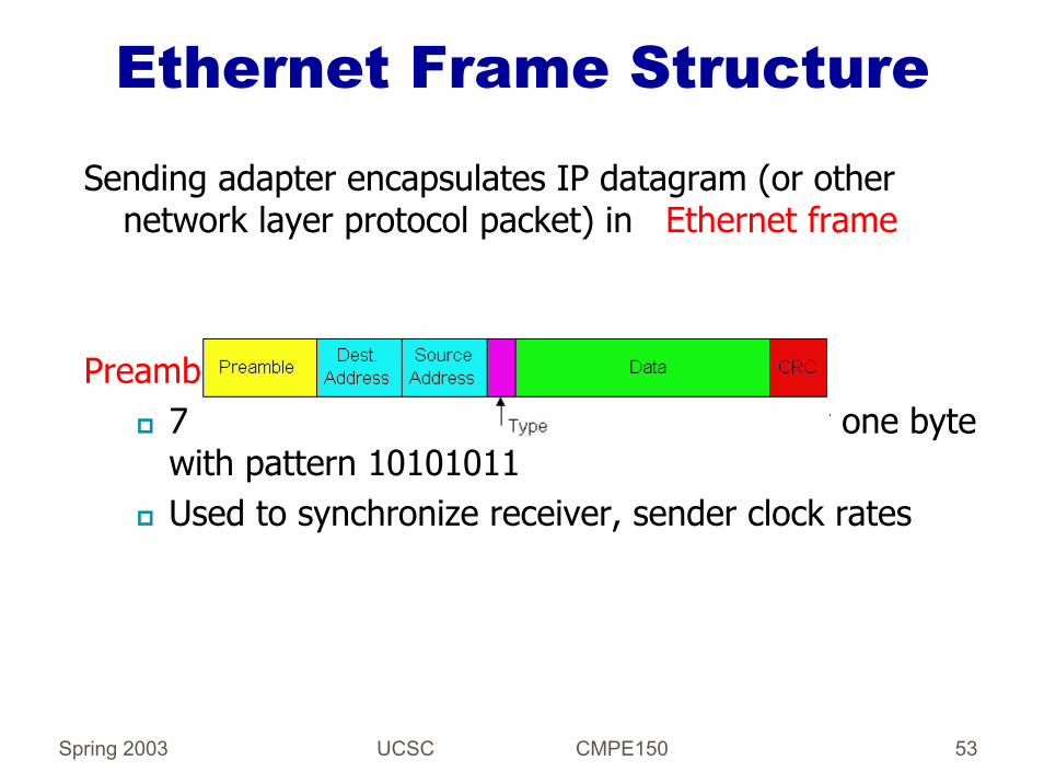
Ethernet Frame Structure
Sending adapter encapsulates IP datagram (or other network layer protocol packet) in Ethernet frame
Preamble:7 bytes with pattern 10101010 followed by one byte with pattern 10101011Used to synchronize receiver, sender clock rates

Spring 2003 UCSC CMPE150 54
Unreliable, Connectionless Service
Connectionless: No handshaking between sending and receiving adapter. Unreliable: receiving adapter doesn’t send acks or nacks to sending adapter.
Stream of datagrams passed to network layer can have gaps.Gaps will be filled if app is using TCP.Otherwise, app will see the gaps.
Spring 2003 UCSC CMPE150 55
Ethernet uses CSMA/CDNo slotsAdapter doesn’t transmit if it senses that some other adapter is transmitting, that is, carrier senseTransmitting adapter aborts when it senses that another adapter is transmitting, that is, collision detection
Before attempting a retransmission, adapter waits a random time, that is, random access

Spring 2003 UCSC CMPE150 56
Ethernet Technologies: 10Base2
10: 10Mbps; 2: under 200 meters max cable length.Thin coaxial cable in a bus topology.
Repeaters used to connect up to multiple segments.Repeater repeats bits it hears on one interface to its other interfaces: physical layer device only!Has become a legacy technology.

Spring 2003 UCSC CMPE150 57
10BaseT and 100BaseT10/100 Mbps rate; latter called “fast ethernet”T stands for Twisted PairNodes connect to a hub: “star topology”; 100 m max distance between nodes and hub
Hubs are essentially physical-layer repeaters:bits coming in one link go out all other linksno frame bufferingno CSMA/CD at hub: adapters detect collisionsprovides net management functionality
hub
nodes

Spring 2003 UCSC CMPE150 58
Gbit Ethernet
Use standard Ethernet frame formatAllows for point-to-point links and shared broadcast channelsIn shared mode, CSMA/CD is used; short distances between nodes to be efficientUses hubs, called here “Buffered Distributors”Full-Duplex at 1 Gbps for point-to-point links10 Gbps now !
Spring 2003 UCSC CMPE150 59
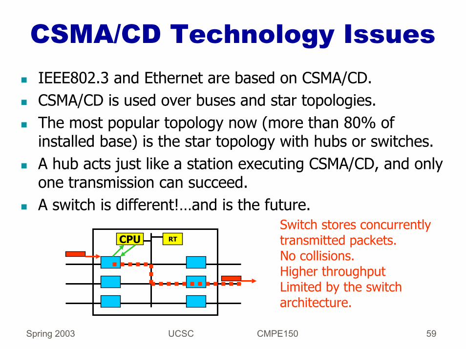
CSMA/CD Technology IssuesIEEE802.3 and Ethernet are based on CSMA/CD.CSMA/CD is used over buses and star topologies.The most popular topology now (more than 80% of installed base) is the star topology with hubs or switches.A hub acts just like a station executing CSMA/CD, and only one transmission can succeed.A switch is different!…and is the future.
Switch stores concurrently transmitted packets.No collisions.Higher throughputLimited by the switch architecture.
CPU RT
Spring 2003 UCSC CMPE150 60
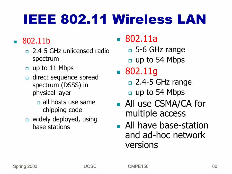
IEEE 802.11 Wireless LAN802.11a
5-6 GHz rangeup to 54 Mbps
802.11g2.4-5 GHz rangeup to 54 Mbps
All use CSMA/CA for multiple accessAll have base-station and ad-hoc network versions
802.11b2.4-5 GHz unlicensed radio spectrumup to 11 Mbpsdirect sequence spread spectrum (DSSS) in physical layer
all hosts use same chipping code
widely deployed, using base stations

Spring 2003 UCSC CMPE150 61
Base-Station ApproachWireless host communicates with a base station
base station = access point (AP)
Basic Service Set (BSS) (a.k.a. “cell”) contains:Wireless hostsAccess point (AP): base station
BSS’s combined to form distribution system (DS)

Spring 2003 UCSC CMPE150 62
Ad Hoc Network approachNo AP (i.e., base station)wireless hosts communicate with each other
to get packet from wireless host A to B may need to route through wireless hosts X,Y,Z
Applications:“laptop” meeting in conference room, carinterconnection of “personal” devicesbattlefield
IETF MANET (Mobile Ad hoc Networks) working group

Spring 2003 UCSC CMPE150 63
Summary of Bluetooth
Low-power, small radius, wireless networking technology
10-100 meters
omnidirectionalnot line-of-sight infared
Interconnects gadgets2.4-2.5 GHz unlicensed radio bandup to 721 kbps
Interference from wireless LANs, digital cordless phones, microwave ovens:
frequency hopping helps
MAC protocol supports:error correctionARQ
Each node has a 12-bit address

Spring 2003 UCSC CMPE150 64
Logical Link Control
MAC protocol provides best effort service.Even when ACKs are used in the MAC, the LLC layer can decide when to retransmit.LLC bridges the gap between service expected by network layer and service provided by MAC layer.LLC uses the header information in MAC frames.Example: PPP (LLC) over Ethernet (MAC)
Spring 2003 UCSC CMPE150 65
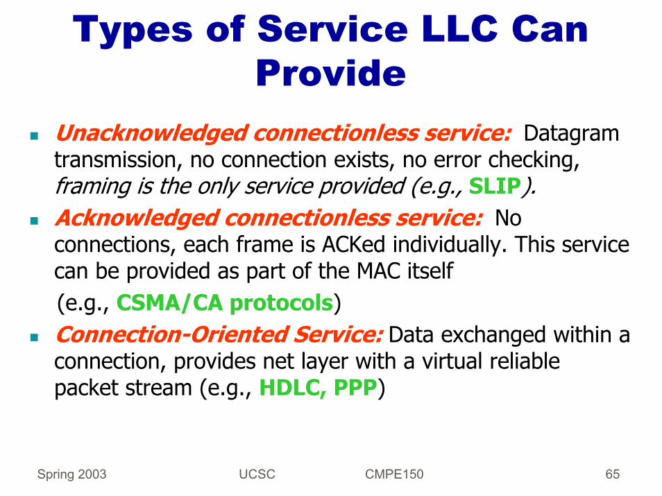
Types of Service LLC Can Provide
Unacknowledged connectionless service: Datagram transmission, no connection exists, no error checking, framing is the only service provided (e.g., SLIP).Acknowledged connectionless service: No connections, each frame is ACKed individually. This service can be provided as part of the MAC itself (e.g., CSMA/CA protocols)Connection-Oriented Service: Data exchanged within a connection, provides net layer with a virtual reliable packet stream (e.g., HDLC, PPP)

Spring 2003 UCSC CMPE150 66
Generic ARQ SchemeSENDER INITIATED
SENDER RECEIVERSEQ. # CRC
PACKET
ACK
TIMEOUT
retransmitif no ACK
acknowledge packetif no errors
time time

Spring 2003 UCSC CMPE150 67
Requirements in ARQSender labels each packet it sends using a linear sequence-number space.Receiver ACKs each packet it receives without errors and numbers each ACK with the sequence number of the corresponding packet.Sender times out after not receiving an ACK for the packet within some finite amount of time, and retransmits the packet then.Sender sends up to a certain number of un-ACKed packets.
Spring 2003 UCSC CMPE150 68
Stop-and-Wait ARQSender transmits packets labeled 1, 2,…..Receiver ACKs every packet received correctly and ACK specified the packet being acknowledged (or next expected packet).Receiver passes copy of packet correctly received to the network layer and drops packets with errors.Sender retransmits copy of packet if no ACK arrives within a timeout interval.Sender and receiver are initialized to start sending and receiving packet 1.

Spring 2003 UCSC CMPE150 69
Selective Repeat ARQMotivation: SWP leaves sender idle for long periods of time waiting for ACKs.Solution: Allow sender to transmit multiple packets while waiting for the ACK of a given packet. Have a pipeline of packets!Requirements:
Sender and receiver can buffer a number (W ) of packetsSender labels packets using consecutive numbers 1, 2,….Receiver buffers packets received without error, ACKs them, and delivers packets to network layer in the correct order(e.g., if packet P1 is in error and P2 and P3 are received correctly, the receiver buffers them until it receives P1 correctly)Sender buffers copies of transmitted packet until it receives the corresponding ACK.Sender retransmits a packet when its timeout expires with no ACK.ACK refers to the sequence number of the packet it acknowledges.

Spring 2003 UCSC CMPE150 70
Sequence Numbering in SRPAssume that window is W and packets are numbered modulo 2W(from 0 to 2W -1)Assume that, at time T, packet labeled n is passed to network layer at the receiver (and is the packet with the highest number that can be passed to net layer).
time
T
R
n
=> n+1 has not beenreceived!
(o.w., it would have been sent to network layer)
sender sent packet n <=
=> sender received all ACKsup to ACK(n-W), because window is W
=> ACK(n+1) not sent to sender=> Smallest sequence number pending an ACK at the sender is n-W+1
=> Largest sequence number sent by sender is n+W
Given n, the possible range of sequence numbers of packets at the sender is {n-W+1, n+W} and using modulo 2W sequence number space works correctly

Spring 2003 UCSC CMPE150 71
Go-Back-N (GBN) ARQSRP requires sender and receiver to have a buffer, which is not an issue today.With GBN, the receiver discards any packet it receives out of order; therefore, it does not need a buffer.Receiver accepts only those packets received in order.Receiver ACKs a packet received correctly with the sequence number of the last packet received in sequence.The sender starts a timer for each packet it transmits, and after the timeout of a packet expires, it retransmits the packet and all the packets sent after that packet.Sender can have up to W packets waiting for ACKs.
Spring 2003 UCSC CMPE150 72
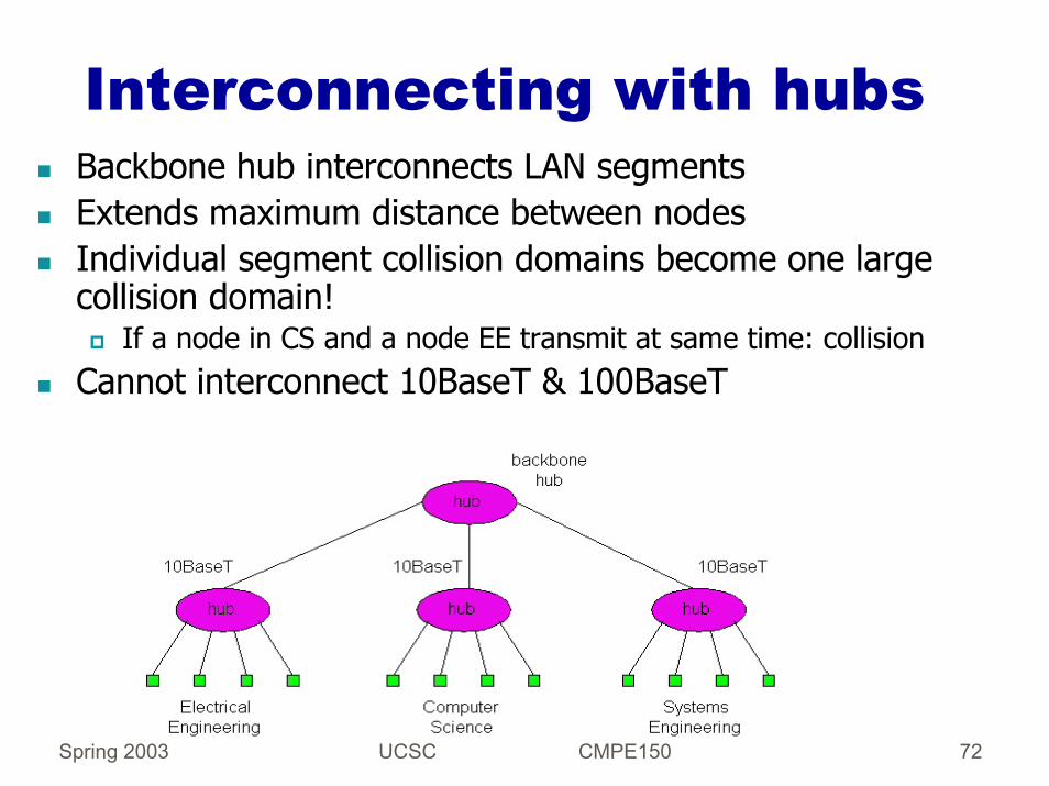
Interconnecting with hubsBackbone hub interconnects LAN segmentsExtends maximum distance between nodesIndividual segment collision domains become one large collision domain!
If a node in CS and a node EE transmit at same time: collisionCannot interconnect 10BaseT & 100BaseT

Spring 2003 UCSC CMPE150 73
Internetworking with BridgesBridges are used to interconnect LANs at the link layer.Frame forwarding from one LAN to another is based on the destination’s link-level address (MAC address) without making any changes to the frame.A MAC address is a name, and for a bridge the address of the destination is the adjacent LAN over which the frames to the destination should be forwarded.Plug-and-play, self-learning
bridges do not need to be configured.

Spring 2003 UCSC CMPE150 74
Traffic Isolation with BridgesBridge installation breaks LAN into LAN segments
Bridges filter packets:Same-LAN-segment frames not usually forwarded onto other LAN segmentsLAN segments become separate collision domains
bridge collision domain
collision domain
= hub= host
LAN segment LAN segment
LAN (IP network)

Spring 2003 UCSC CMPE150 75
Internetworking with Bridges
To which LAN segment should the bridge forward a frame?A routing problem!There are two types of bridges that have been used:
Transparent Source routing

Spring 2003 UCSC CMPE150 76
Transparent Bridges: Summary
The purpose of transparent bridges is to keep the packet forwarding functionality transparent to the hosts.Transparent bridges establish and manage a spanning tree of the network to eliminate packet looping.The address of a station is always the LAN over which packets from that station came last; this is a dynamic process.If no address is known, a bridge broadcasts packets for a station over all its ports (or those in the spanning tree).

Spring 2003 UCSC CMPE150 77
Bridges in Mesh TopologiesAlternative paths from source to destination LANs are desirable for increased reliability.
Disabled

Spring 2003 UCSC CMPE150 78
Spanning Tree Algorithm (STA)The objective is to define a single spanning tree in the internet over which packets flow without looping.Basis of operation (Perlman 1992, part of IEEE standard):
Elect distributedly a single bridge as the root of the tree Calculate distance (in hops) on a shortest path to rootElect a designated bridge for each LAN (e.g., closest to the root in the LAN)Allow only designated bridge to forward packets to and from its LAN
A distributed election process is used to build the spanning tree!
root

Spring 2003 UCSC CMPE150 79
STA OperationEach bridge has multiple MAC addresses (one per port)A bridge has a bridge-wide ID (one of the MAC addresses)HELLOs: messages used to build tree, sent to all bridges of a LANHELLO specifies:
Root ID: The MAC address of the bridge assumed to be the rootTransmitting bridge ID: MAC address of bridge sending HELLOCost: Length (in hops) of path from bridge to root
A bridge starts by considering itself the proposed rootBridge starts election process by sending
HELLO = own ID, 0, own ID
Spring 2003 UCSC CMPE150 80
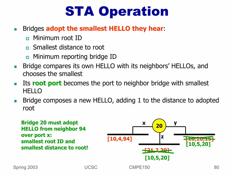
STA OperationBridges adopt the smallest HELLO they hear:
Minimum root IDSmallest distance to rootMinimum reporting bridge ID
Bridge compares its own HELLO with its neighbors’ HELLOs, and chooses the smallestIts root port becomes the port to neighbor bridge with smallest HELLOBridge composes a new HELLO, adding 1 to the distance to adoptedroot
20x y
z
[21,2,30]
[10,4,94] [10,20,15]
[10,5,20]
[10,5,20]
Bridge 20 must adopt HELLO from neighbor 94 over port x:smallest root ID and smallest distance to root!

Spring 2003 UCSC CMPE150 81
STA OperationBridge sends new HELLO over all ports from which “larger” HELLOs were received.Bridge knows if it is the designated bridge for a LAN if it does not hear a “smaller” HELLO than its own.Its root port is the port from which the smallest HELLO was received.Bridge puts its root port and all ports for which it is the designated bridge in forwarding state.Bridge puts all other ports in blocking state.Data packets, control packets, and learning of addresses take place only over ports in forwarding state (over the spanning tree).

Spring 2003 UCSC CMPE150 82
Example of STA Operation
[10,4,94]
[21,2,30][10,5,20]
[10,4,50]
[10,20,15]
[10,5,20]
20x y
z
v
[10,4,50]
root port forwarding mode
forwarding mode

Spring 2003 UCSC CMPE150 83
Example
4
5
107
20
33
root
5
33
10
20
4
7

Spring 2003 UCSC CMPE150 84
Bridges vs. RoutersBoth store-and-forward devices
Routers: network layer devices (examine network layer headers)Bridges are link layer devices
Routers maintain routing tables, implement routing algorithmsBridges maintain bridge tables, implement filtering, learning and spanning tree algorithms

Spring 2003 UCSC CMPE150 85
Routers vs. Bridges
Bridges + and -+ Bridge operation is simpler requiring less packet
processing.+ Bridge tables are self learning.
- All traffic confined to spanning tree, even when alternative bandwidth is available.
Spring 2003 UCSC CMPE150 86
Routers vs. BridgesRouters + and -+ arbitrary topologies can be supported, cycling is limited
by TTL counters (and good routing protocols)+ provide protection against broadcast storms
- require IP address configuration (not plug and play)- require higher packet processing
bridges do well in small (few hundred hosts) while routers used in large networks (thousands of hosts)
Spring 2003 UCSC CMPE150 87
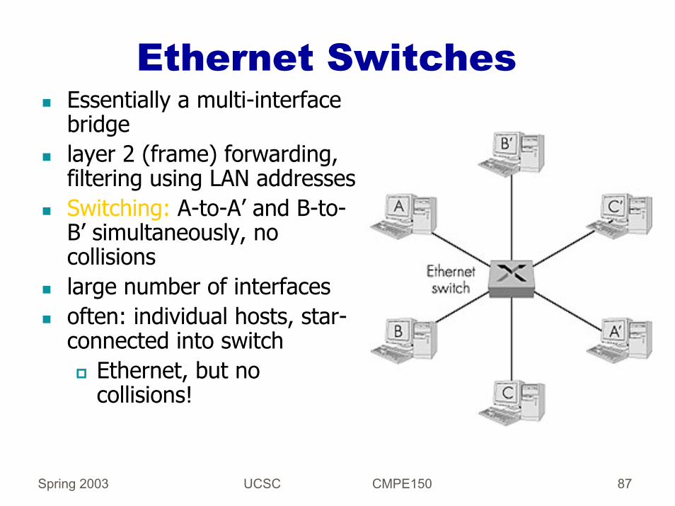
Ethernet SwitchesEssentially a multi-interface bridgelayer 2 (frame) forwarding, filtering using LAN addressesSwitching: A-to-A’ and B-to-B’ simultaneously, no collisionslarge number of interfacesoften: individual hosts, star-connected into switch
Ethernet, but no collisions!

Spring 2003 UCSC CMPE150 88
Network LayerThe main functions at the network layer are addressing, routing, congestion control, and admission control.Addressing consists of identifying where a destination is with respect to the network topology.Routing consists of (a) computing paths from sources to destinations and (b) forwarding packets along such paths.Congestion control consists of limiting the amount of data a source can sent into the network.Admission control consists of limiting the number of sources allowed to send data into the network, and in a way is part of system-wide congestion control.
Spring 2003 UCSC CMPE150 89
Routing AlgorithmsMost books and papers classify routing algorithms into distance-vector and link-state algorithms.Distance-Vector Algorithm: Routers exchange their distances to known destinations; a router uses the distance vectors received from its neighbors to compute its own distances. Computation is distributed.Link-State Algorithm: Routers exchange information about the state of the links in the network; a router uses this information to compute its distances to destinations. Computation is local.
This is a very limiting view!

Spring 2003 UCSC CMPE150 90
Shortest-Path RoutingProblem: Compute the path of minimum length from each router to each destinationNotation: G(N, E) is the network of |N| nodes and |E| links
ikl
(i, k)
),( 1 hop
+∈∀
∑= iPh
iij hhlD
iji
p
j
h2 hx
….k
i
q
ijP
iN
Spring 2003 UCSC CMPE150 91
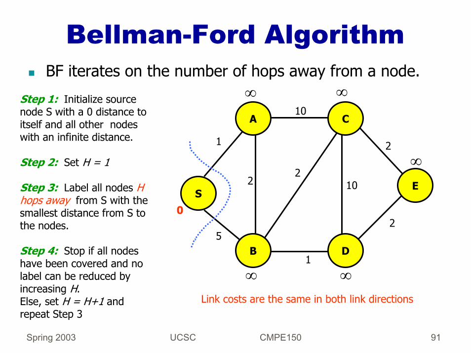
Bellman-Ford AlgorithmBF iterates on the number of hops away from a node.
S
A
B D
E
C
1
5
2
10
2
2
1
10
20
∞ ∞
∞
Step 1: Initialize source node S with a 0 distance to itself and all other nodes with an infinite distance.
Step 2: Set H = 1
Step 3: Label all nodes H hops away from S with the smallest distance from S to the nodes.
Step 4: Stop if all nodes have been covered and no label can be reduced by increasing H. Else, set H = H+1 and repeat Step 3
∞∞Link costs are the same in both link directions

Spring 2003 UCSC CMPE150 92
Bellman-Ford AlgorithmH = 4:
S
A
B D
E
C
1
5
2
10
2
2
1
10
20
1
3
5
4
6
4
No more nodes can be reached and no label can be reduced

Spring 2003 UCSC CMPE150 93
Distributed Bellman-Ford Algorithm (DBF)
The objective of DBF is to have a distributed implementation of BF, so that routers can compute distances to destinations distributedly.To accomplish this, the computation of a distance to a destination starts at the destination itself.The iteration of DBF is on the number of hops away from a destination.DBF operates independently for each destination.Destination starts by stating the distance to itself is 0The neighbors of the destination receive this information, process it and send their own updates.Distances propagate throughout the network.

Spring 2003 UCSC CMPE150 94
DBFInformation maintained at each router:
Distance Table: Distance to each destination reported by each neighbor Link-Cost Table: Cost of link to each adjacent nodeRouting Table: Distance and successor (next hop) to each destination
Information exchanged among routers:Vector of one or more entries, each entry stating the distance to a destination
Services assumed:Update messages are exchanged reliably, a node knows who its neighbors are

Spring 2003 UCSC CMPE150 95
Example of DBF OperationFor simplicity, we will assume “synchronous operation” in all cases!
234 1
22
33
44
time
0
11
d c jab 1111

Spring 2003 UCSC CMPE150 96
Counting to Infinity in DBFThe problem with DBF is that it does not have a termination detection mechanism!
d c jab1234 X
3 = 2+1
4 = 3+14
55 55
6666
77 77
time…. etc

Spring 2003 UCSC CMPE150 97
Ad Hoc Solutions (do not work)
Counting to N takes too long! Alternatives include:Split horizon: Does not report routes through a successor to the successor itself.Hold-down timer: After distance to destination increases, send update stating new distance through current successor, wait for a long period of time before computing new successor and shortest distance and then act as in DBF.Poisoned reverse: After distance increase, report an infinite distance and then correct the distance. (Or in general, reporting infinity to the successor of destinations routed through it).Next-hop information: Communicate the distance and next hop to each destination (used in RIP v2)
Spring 2003 UCSC CMPE150 98
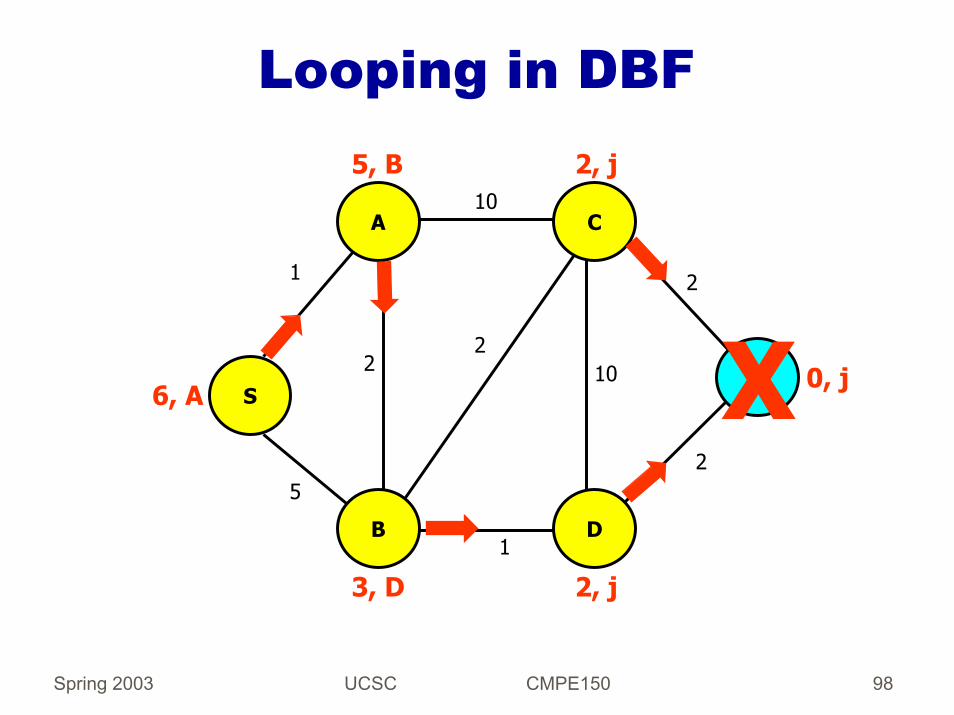
Looping in DBF
S
A
B D
j
C
1
5
2
10
2
2
1
10
2
2, j
2, j3, D
5, B
6, A X 0, j

Spring 2003 UCSC CMPE150 99
Looping in DBF
S
A
B D
C
1
5
2
10
2
1
10
3, D
5, B
6, A
5,B
5
4, B
4

Spring 2003 UCSC CMPE150 100
Looping in DBFErroneous paths persist as long as they appear to be the shortest paths.
Similar looping could occur if the cost of the links to j increased drastically (e.g., to 20).
DBF cannot be used with link costs that have a large variance!
S
A
B D
C
1
5
2
10
2
1
10
3, D
5, B
6, A
5,B
4, B
5 … etc

Spring 2003 UCSC CMPE150 101
Traditional Link-State Algorithm (LSA)
Developed as a result of DBF’s looping and non-termination problems.Two components:
Topology map distributionLocal shortest path computation
Each router runs a local shortest-path algorithm (Dijkstra’s) using the topology stored locally.Flooding is used to replicate the topology map at every router.Each router is responsible for reporting the state of outgoing links to the rest of the network.Two link-state updates per link reach every router.

Spring 2003 UCSC CMPE150 102
Shortest-Path First (SPF) Algorithm
Step 1: InitializeSet SPF = { root }, where root is router running SPFDistance to root = 0 and distance to other nodes = cost of link or infinity
Step 2: Find next node for SPF set:Find a node x not in SPF set such that:distance to/from root =
Min{distance to node outside of SPF set}Augment SPF set with xStop if SPF set contains all nodes
Step 3: Change minimum distance:For each node y outside SPF set do:dist. to y = Min{ dist. to y, dist. to z in SPF + cost of (z, y) }Repeat Step 2

Spring 2003 UCSC CMPE150 103
SPF ExampleSPF ={S, A, B, D}
Note that iteration is on the next node that can be covered with the next shortest path; hence complete topology must be known by router.
S
A
B D
E
C
1
5
2
10
2
2
1
10
20
1
∞
3
5
4
6SPF ={S, A, B, D, C}
SPF ={S, A, B, D, C, E}
Stop after covering E since all nodes are covered by SPF set.
Labels do not change as we continue to expand SPF set

Spring 2003 UCSC CMPE150 104
Flooding of Link States
Information Stored at Routers:Each router maintains all the nodes and all the links in the network in a topology graph. Each link in the graph has a cost, a sequence number, and an age.
Spring 2003 UCSC CMPE150 105
Flooding of Link StatesInformation Exchanged:
Each router is responsible for communicating the latest state of each adjacent outgoing link.The router sends a link state update (LSU) to report changes on an adjacent outgoing link.A sequence number is used to identify the latest LSU.An LSU also specified the age of the LSU, and the age of an LSU is decremented each time it is forwarded and while it is in storage.We assume that LSUs are exchanged reliably between any two routers and that a router knows who its neighbors are!

Spring 2003 UCSC CMPE150 106
IP InternetworkingBased on Cerf’s catenet model V.G. Cerf, “The Catenet Model for Internetworking,” IEN 48, July 1978.
Basic premises:Heterogeneous transmission mediaHeterogeneous hardware and OS in hosts and gatewaysCommon protocol for network interconnection runs in all gateways and hosts!Common protocol used for data transfer and signalingCommon address space used to identify where a host or router is in the internetworkAn address states at which network a node attaches to the internetwork

Spring 2003 UCSC CMPE150 107
Service Model: Theory and Practice
The Internet Protocol (IP) evolved from the catenet model.Theory: Datagram Delivery is assumed, so that packets can get lost, out of order, and multiple copies can be delivered.Practice:
TCP needs in-order delivery of packets to work efficiently, and (as we will see) Internet routing protocols provide a single path for each destination and do not adapt very rapidly.Too many destinations!
Spring 2003 UCSC CMPE150 108
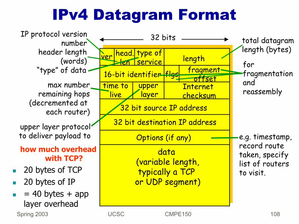
IPv4 Datagram Format
ver length
data (variable length,typically a TCP
or UDP segment)
16-bit identifierInternetchecksum
time tolive
32 bit source IP address
IP protocol versionnumber
header length(words)
max numberremaining hops
(decremented at each router)
forfragmentationandreassembly
total datagramlength (bytes)
upper layer protocolto deliver payload to
head.len
type ofservice
“type” of data flgs fragmentoffset
upperlayer
32 bit destination IP address
Options (if any)how much overhead
with TCP?20 bytes of TCP20 bytes of IP= 40 bytes + app layer overhead
32 bits
e.g. timestamp,record routetaken, specifylist of routers to visit.
Spring 2003 UCSC CMPE150 109
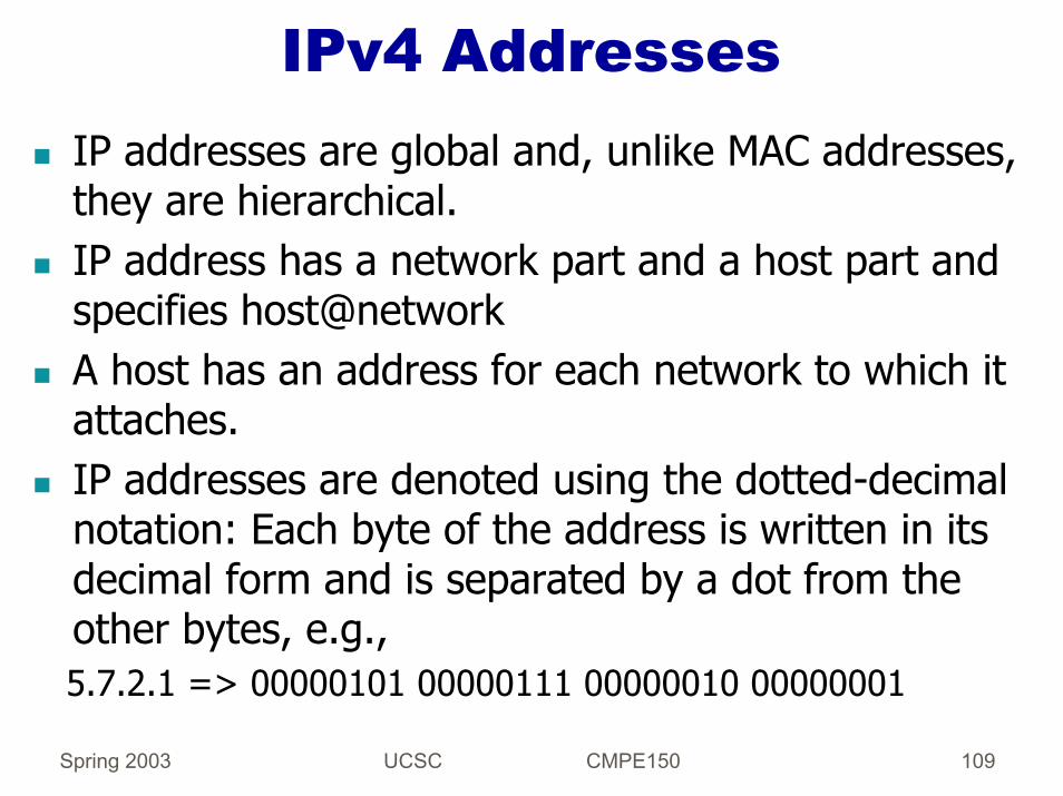
IPv4 AddressesIP addresses are global and, unlike MAC addresses, they are hierarchical.IP address has a network part and a host part and specifies host@networkA host has an address for each network to which it attaches.IP addresses are denoted using the dotted-decimal notation: Each byte of the address is written in its decimal form and is separated by a dot from the other bytes, e.g.,5.7.2.1 => 00000101 00000111 00000010 00000001

Spring 2003 UCSC CMPE150 110
IPv4 Addresses (past)8 16 24 310
0
network
network10
16 million
65,534
110
126
16,382
2 million
network hostClass A
Class B host
hostClass C
254
multicast address
reserved address
1110
11110
Class D
Class E

Spring 2003 UCSC CMPE150 111
IPv4 Addressing ProblemsThere were too few networks left due to the class structure used in IP address assignments!There are many more IP devices and appliances coming.Routing tables cannot have millions of entries.Solutions:
Aggregation of addresses without classes (subnetting, and now CIDR)New and bigger global address space (IPv6)Locally unique addresses (NAT and other techniques)
Spring 2003 UCSC CMPE150 112
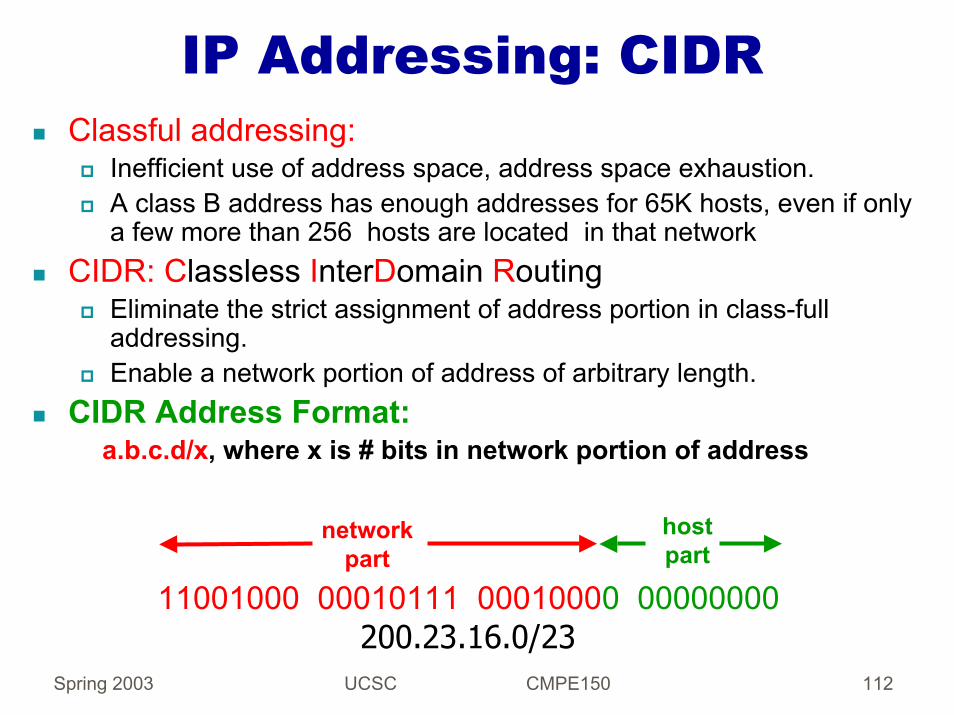
IP Addressing: CIDRClassful addressing:
Inefficient use of address space, address space exhaustion.A class B address has enough addresses for 65K hosts, even if only a few more than 256 hosts are located in that network
CIDR: Classless InterDomain RoutingEliminate the strict assignment of address portion in class-full addressing.Enable a network portion of address of arbitrary length.
CIDR Address Format: a.b.c.d/x, where x is # bits in network portion of address
11001000 00010111 00010000 00000000
networkpart
hostpart
200.23.16.0/23

Spring 2003 UCSC CMPE150 113
Assigning Blocks of Addresses to ISPs
ICANN: Internet Corporation for Assigned Names and NumbersAllocates IP address spaceManages DNS (domain name system)Assigns domain names and resolves disputes

Spring 2003 UCSC CMPE150 114
Internet Control ProtocolsIn addition to packet forwarding and keeping routing tables correct, sending IP packets requires a number of control protocols:
Application has the name of an intended destination.An IP address has to be found for that name;The application typically calls a resolver in the Domain Name System (DNS) or uses a static hosts file (e.g., /etc/hosts)Host determines if destination IP address is the same or different.If different, packet is sent to an attached (default) router.If same subnet, the IP address must be converted to a MAC address using a protocol (ARP).Destination router must also map IP address to MAC address usingARP.Errors may have to be reported to the source of an IP packet using a protocol (ICMP).

Spring 2003 UCSC CMPE150 115
FragmentationPacket length is in bytes and includes header; maximum length is then 65,535 bytesMAC protocol my not support such long packets, and an IP packet may have to be fragmented.
Ethernet accepts frames of up to 1500 bytes and FDDI of up to 4500 bytes
Each fragment is a self-contained datagram.Fragmentation is handled with:
The packet ID, which is the same for all fragmentsThe offset, which states the byte (position) of the fragmentA flag indicating that there a more fragments for the same ID coming.

Spring 2003 UCSC CMPE150 116
IPv4 HeaderTTL (time to live indicates how long the packet can stay in the network; it is specified in hops and is decremented each time the packet is forwarded.
Default is 64 hops; nodes can play with the field to limit the scopeProtocol specifies the type of payloadChecksum is computed considering the entire header as a sequence of 16-bit words, adding them up with 1’s complement arithmetic and taking the 1’s complement of the result.This checksum is NOT as powerful as a CRC but is simple to do in software.Why this way? Because it is done at each hop (software)What if we process headers in hardware?

Spring 2003 UCSC CMPE150 117
Error ReportingIn general, errors can be reported to the origin of a packet or to intermediate relays or both.In the IP Internet, errors are reported to the source using ICMP (internet control message protocol).The choice stems from using IP for all signaling and user data transfer in the Internet.ICMP messages are encapsulated in IP.An IP packet specifies the source and destination and not the relays (options are not supported in general)

Spring 2003 UCSC CMPE150 118
Address Resolution ProtocolGoal: Enable a host to build a table of mappings between IP addresses and MAC addresses in a dynamic manner.Mappings are called ARP cache or ARP table.Approach:
ARP is designed assuming a fully connected, broadcast link layer (LAN) and the requestor is responsible for persisting.Hosts and routers broadcast requests and responses and listen to requests and responses from any other node in the LAN.Different approach would be needed in a multihop LAN.

Spring 2003 UCSC CMPE150 119
Dynamic Host ConfigurationHost must be assigned an IP address, because it is not committed to hardware as a MAC address.Configuring hosts with proper IP addresses is involved.DHCP (dynamic host configuration protocol) is a solution to this configuration and management problem.DHCP is intended to support manual, automatic and dynamic configurationsDHCP is designed to work with no pre-configured addresses of servers and across networks.

Spring 2003 UCSC CMPE150 120
DHCP: Dynamic Host Configuration Protocol
Goal: Allow host to dynamically obtain its IP address from network server when it joins network.Can renew its lease on address in useAllows reuse of addresses
only hold address while connected and “on”Support for mobile users who want to join network (more shortly)
DHCP overview:host broadcasts “DHCP discover” msgDHCP server responds with “DHCP offer” msghost requests IP address: “DHCP request” msgDHCP server sends address: “DHCP ack” msg

Spring 2003 UCSC CMPE150 121
NAT: Network Address Translation
10.0.0.1
10.0.0.2
10.0.0.3
10.0.0.4
138.76.29.7
local network(e.g., home network)
10.0.0/24
Datagrams with source or destination in this networkhave 10.0.0/24 address for source, destination (as usual)
All datagrams leaving localnetwork have same single source
NAT IP address: 138.76.29.7,different source port numbers
rest ofInternet
Spring 2003 UCSC CMPE150 122
NAT Motivation
Local network uses just one IP address as far as outside word is concerned
No need to be allocated range of addresses from ISP: - just one IP address is used for all devicesCan change addresses of devices in local network without notifying outside worldCan change ISP without changing addresses of devices in local networkDevices inside local net not explicitly addressable, visible by outside world (a security plus).

Spring 2003 UCSC CMPE150 123
Functions of NAT RouterOutgoing datagrams:Replace (source IP address, port #) of every outgoing datagram to (NAT IP address, new port #). . . remote clients/servers will respond using (NAT IP
address, new port #) as destination addr.Remember (in NAT translation table)every (source IP address, port #) to (NAT IP address, new port #) translation pairIncoming datagrams:Replace (NAT IP address, new port #) in dest fields of every incoming datagram with corresponding (source IP address, port #) stored in NAT table

Spring 2003 UCSC CMPE150 124
NAT Issues16-bit port-number field:
60,000 simultaneous connections with a single LAN-side address!
NAT is controversial:Routers should only process up to layer 3Violates end-to-end argument
NAT possibility must be taken into account by app designers, e.g., P2P applications
Should address shortage be solved using IPv6 instead?

Spring 2003 UCSC CMPE150 125
NAT IssuesViolates the architectural model
“Every IP address uniquely identifies a single machine” (now many use 10.0.0.1)
Move from connectionless to connection orientedNAT router must maintain state for each connection – if it crashes, all connections are destroyed
NAT violates protocol layering.If TCP/UDP change. Different header, etc. NAT will fail.. NAT removes the independence of the layers
Transport protocols other than TCP/UDP will likely fail at a NAT routerSome applications place IP address in the data for the receiver to use. NAT will not find and translate these16-bit port-number field:
Maximum of 60,000 simultaneous connections with a single Ip address
RFC 2993 discusses these and other problems
Spring 2003 UCSC CMPE150 126
Internet Routing ProtocolsIntra-domain routing:
RIP, OSPF, EIGRPSingle-path routing protocols, static link costsPerformance (shortest path)
Inter-domain routing:Border Gateway Protocol (BGP)Single pathPolicy based

Spring 2003 UCSC CMPE150 127
RIP (v1)Based on DBFUsed in small internetsProblems: Counting to infinity and looping, single-path routing, link cost should be 1 or infinityUpdate specifies only a destination network and a distance to it; hence, no variable subnet masks are allowed in “local” internet and a static subnetting convention must be used for all routers Router sends its routing table to its neighbors every 30 sec. or when it must update its routing table.Runs on top of UDP.

Spring 2003 UCSC CMPE150 128
RIPv2Adds the next hop to a destination and subnet mask in each update.Variable subnets are allowed.Performance does not improve much.
Spring 2003 UCSC CMPE150 129
OSPF: Open Shortest Path FirstDijkstra’s SPF used to compute shortest paths locally based on topology map.Flooding is used to disseminate topology maps.Sequence numbers and age fields are used to validate link-state updates.Runs on top of IP and implements its own reliable transmission of link-state updates.Designated routers are used to reduce overhead within a LAN, and areas connected by a backbone are used to reduce overhead across LANs.HELLOs used to identify neighbors.

Spring 2003 UCSC CMPE150 130
BGPBGP (Border Gateway Protocol): the de facto standard for Internet inter-AS routing.Path Vector protocol:
Similar to Distance Vector protocolEach Border Gateway broadcast to neighbors (peers) entire path (i.e., sequence of AS’s) to destinationBGP routes to networks (ASs), not individual hostse.g., Gateway X may send its path to dest. Z:Path (X,Z) = X,Y1,Y2,Y3,…,Z

Spring 2003 UCSC CMPE150 131
Routing in Ad Hoc NetworksThe problem addressed is host and router mobility.IETF MANET Working Group is defining which approach to evolve into a standard.Proposals:
On-demand routing approaches: DSR, AODV, TORA, and many others.Table-driven and hybrid approaches: STAR and approaches based on topology broadcast.

Spring 2003 UCSC CMPE150 132
On-Demand RoutingRouters maintain routing-table entries for only those destinations that they need to reach.To reach a destination with an unknown route, source sends a flood search packet, just like in source routing bridges.Flood search packet reaches the destination one or multiple times.Destination sends a reply one or multiple times with the desired routing information.DSR uses source routes in flood searches and replies; AODV uses destination sequence numbers.

Spring 2003 UCSC CMPE150 133
Multicast: one sender to many receivers
Multicast: act of sending datagram to multiple receivers with single “transmit” operation
analogy: one teacher to many students
Spring 2003 UCSC CMPE150 134
IP Multicast Architecture
Based on Steve Deering’s original proposal (SIGCOMM 88 Proceedings; his PhD thesis)It consists of three basic components:
Group addressing based on globally uniqueidentifiers (IP multicast addresses)Separation of senders and receivers with anonymous receiver affiliationA tree-based routing and group structure
Spring 2003 UCSC CMPE150 135
IP Multicast Architecture (contd..)
128.119.40.186
128.59.16.12
128.34.108.63
128.34.108.60
multicast group
226.17.30.197
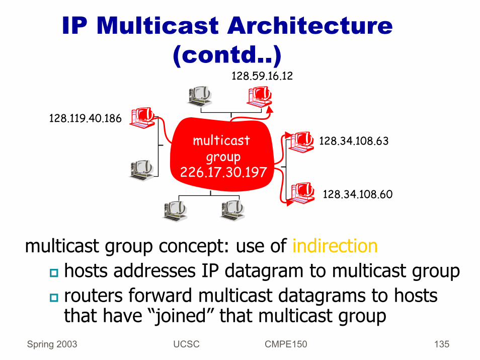
multicast group concept: use of indirectionhosts addresses IP datagram to multicast grouprouters forward multicast datagrams to hosts that have “joined” that multicast group

Spring 2003 UCSC CMPE150 136
IP Multicast Addresses
28 bits for groups ~ 250 million groupsTwo kinds of supported addresses:
Permanent, e.g., 224.0.0.1 all systems on LAN224.0.0.2 all routers on LAN
Temporary - must be created before they can be addressed (join and leave)

Spring 2003 UCSC CMPE150 137
IGMP: Internet Group Management Protocol
host: sends IGMP report when application joins mcast grouprouter: sends IGMP query at regular intervals
host belonging to a mcast group must reply to query
query report

Spring 2003 UCSC CMPE150 138
Distance Vector Multicast Routing Protocol (DVMRP)
DVMRP: distance vector multicast routing protocol, RFC1075flood and prune: reverse path forwarding, source-based tree
RPF tree based on DVMRP’s own routing tables constructed by communicating DVMRP routers no assumptions about underlying unicast
odds and endscommonly implemented in commercial routersMbone routing done using DVMRP

Spring 2003 UCSC CMPE150 139
PIM: Protocol Independent Multicast
not dependent on any specific underlying unicast routing algorithm (works with all)
two different multicast distribution scenarios :
Dense:group members densely packed, in “close” proximity.bandwidth more plentiful
Sparse:# networks with group members small wrt # interconnected networksgroup members “widely dispersed”bandwidth not plentiful

Spring 2003 UCSC CMPE150 140
Consequences of Sparse-Dense Dichotomy:
Densegroup membership by routers assumed until routers explicitly prunedata-drivenconstruction on mcast tree (e.g., RPF)bandwidth and non-group-router processing profligate
Sparse:no membership until routers explicitly joinreceiver- drivenconstruction of mcast tree (e.g., center-based)bandwidth and non-group-router processing conservative

Spring 2003 UCSC CMPE150 141
Mobility Management
Each network is identified by the network prefix part of the IP address.When a node moves from one network to another network, the IP address should change according to the network prefix of the new network.All the connections are identified by the IP address and the port number of the host.
Spring 2003 UCSC CMPE150 142
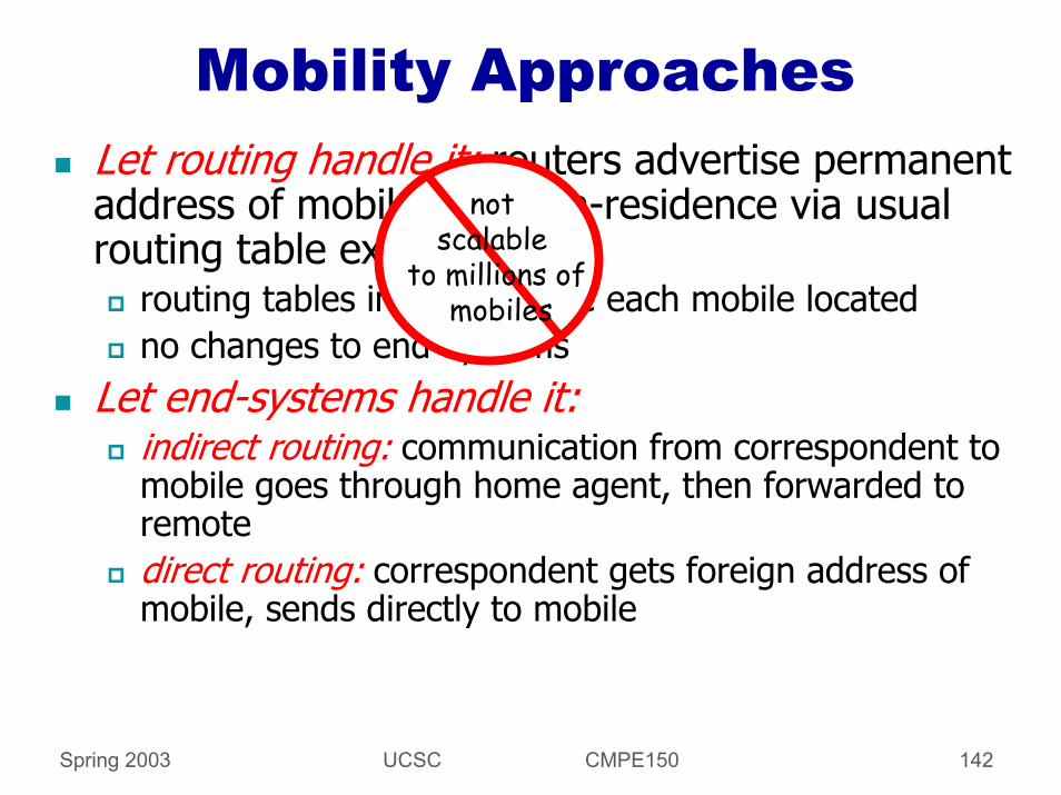
Mobility ApproachesLet routing handle it: routers advertise permanent address of mobile-nodes-in-residence via usual routing table exchange.
routing tables indicate where each mobile locatedno changes to end-systems
Let end-systems handle it: indirect routing: communication from correspondent to mobile goes through home agent, then forwarded to remotedirect routing: correspondent gets foreign address of mobile, sends directly to mobile
not scalable
to millions ofmobiles

Spring 2003 UCSC CMPE150 143
Mobility: Registration
wide area network
home networkvisited network
1
mobile contacts foreign agent on entering visited network
2
foreign agent contacts home agent home: “this mobile is resident in my network”
End result:Foreign agent knows about mobileHome agent knows location of mobile

Spring 2003 UCSC CMPE150 144
Mobility Support via Indirect Routing
wide area network
homenetwork
visitednetwork
3
24
1correspondent addresses packets using home address of mobile
home agent intercepts packets, forwards to foreign agent
foreign agent receives packets, forwards to mobile
mobile replies directly to correspondent

Spring 2003 UCSC CMPE150 145
Mobility via Direct Routing
wide area network
homenetwork
visitednetwork
4
2
41correspondent requests, receives foreign address of mobile
foreign agent receives packets, forwards to mobile
mobile replies directly to correspondent
3
correspondent forwards to foreign agent

Spring 2003 UCSC CMPE150 146
Mobile IPRFC 3220Has many features we have discussed:
Home agents, foreign agents, foreign-agent registration, care-of-addresses, encapsulation (packet-within-a-packet)
Three components to standard:Agent discoveryRegistration with home agentIndirect routing of datagrams
Spring 2003 UCSC CMPE150 147
Transport ProtocolsServices:
Reliable or unreliable transport from source process to end process(es)Multiplexing and demultiplexingFlow control
Avoid overflowing receiver’s buffer
Congestion controlAvoid overflowing the network bottleneck
Examples: UDP and TCP

Spring 2003 UCSC CMPE150 148
Why Multiplexing
IP delivers packets from source host to destination host.However, multiple processes run in the hosts!Applications require communication among processes, not just host computers.Example: Multiple telnet sessions, email, ftp sessions, and www can all be running concurrently in the same host.Ports are defined as the addresses of processes inside a host.How do we identify processes uniquely and efficiently?

Spring 2003 UCSC CMPE150 149
Transport Protocols
Transport protocols used today are point to point!
UDP used for:Remote file server (NFS), name translation (DNS), intra-domain routing (RIP), network management (SNMP), multimedia applications and telephony.
TCP used for:Electronic mail (SMTP), file transfer (FTP), remote login (Telnet), web (HTTP)
No standard multipoint e-t-e protocol yet!

Spring 2003 UCSC CMPE150 150
User Datagram Protocol (UDP)
Provides best effort e-t-e delivery of segments among processes:
No guarantees for delivery, ordering, duplicates
Small overhead, no connection state, no flow control, no congestion control.Header specifies the minimum needed for multiplexing and framing.

Spring 2003 UCSC CMPE150 151
TCP
Flow Control vs. Congestion ControlReliable vs. Unreliable CommunicationTCP
historyservice providedapplicationserror recoverycongestion controlproposed enhancements

Spring 2003 UCSC CMPE150 152
Services Provided
Layer 4 - Transport layerEnd-to-end flow controlReliable byte streamIn-order packet delivery (buffering)Connection-oriented
Socket <host address, port>uniquely identifiable connection

Spring 2003 UCSC CMPE150 153
Connection establishment
client SYN(port,ISN=10) serverconnection request (SYN)
SYN(ISN=35,ACK=11)
ACK = 36connection granted(SYNACK)
ACK
A Three-way handshakeHow to choose ISN?

Spring 2003 UCSC CMPE150 154
Flow Control vs. Congestion Control
Congestion controlGlobal issue: concerns all routers and hosts on path from Source to Destinationmake sure every subnet can handle the traffic
Router
Senders
Router1Mbps 1Mbps1Mbps
Receiver

Spring 2003 UCSC CMPE150 155
Flow Control vs. Congestion Control
Flow ControlInvolves two endpointsMake sure sender doesn’t transmit faster than receiver can absorb packets
Server1Gbps
PC1Mbps
File transfer

Spring 2003 UCSC CMPE150 156
TCP Flow ControlTransmission Window a.k.a. congestion window (cwnd)
Sliding windowmaintained by senderConservation of packets
Receiver’s window set through socket APIcontrolled by the receiveradvertised to the sender in field of TCP header (RAW)
cwnd
1 2 3 4 5 6 7 8 9 10 11 12 ...Sent and ACKed
Sent, not ACKedCan’t send
Send ASAP
Spring 2003 UCSC CMPE150 157
TCP Congestion ControlSlow Start
Due to Van Jacobson (SIGCOMM 88)Algorithm used at beginning of connection and after a timeoutleads to exponential growth in the amount of outstanding data in networkcwnd doubles every RTT !!Algorithm:
When an ACK is received before timeout:
cwnd = cwnd + 1 for each ack’d segment

Spring 2003 UCSC CMPE150 158
Congestion AvoidanceCA is flow control imposed by the sender:
Introduce a new variable, ssthreshinitialized to 65,535 (max. window)
If timeout, set ssthresh = cwnd/2 and cwnd =1Re-enter slow start, until cwnd = ssthreshWhen cwnd = ssthresh, then grow cwnd linearly until it reaches RAW:
ACK is received (before a timeout)
then cwnd = cwnd + 1/cwndHence, cwnd increases by 1 segment every RTT

Spring 2003 UCSC CMPE150 159
Putting it together: Slow start and congestion avoidance
The algorithm:If cwnd < ssthresh
do slow start
Else if cwnd >= ssthreshdo congestion avoidance

Spring 2003 UCSC CMPE150 160
Graph of CA and SS

Spring 2003 UCSC CMPE150 161
TCP Congestion Control: Underdamped Feedback
System!cwnd
ssthresh
ssthresh/2
rt times

Spring 2003 UCSC CMPE150 162
Problems with CA and SS
Slow start is an attempt to discover the network bandwidth
Discovery proceeds by filling network queues in intermediate routers.Once queues are full, routers drop packets.Once loss discovered, it’s too late!TCP sender reduces window when loss is discovered
Queue level oscillates between full and cwnd/2What sort of problems does this introduce??

Spring 2003 UCSC CMPE150 163
Fast Retransmit and Fast Recovery
When third duplicate ACK is detected:Retransmit missing segmentSet ssthresh = cwnd/2Set cwnd = ssthresh + 3
For each additional duplicate ACK:increment cwnd by one segmenttransmit a new packet if possiblewhy? With each ACK, we know a data pkt left the network
When new ACK arrives:cwnd = ssthresh

Spring 2003 UCSC CMPE150 164
Nagle’s AlgorithmSolution proposed in RFC 896 in 1984
For Silly Window SyndromeSolution:
only one outstanding small segment is allowedno additional small segments can be sent until the previous is ACKedOnce the ACK arrives, several small segments will have been buffered and can now be transmittedSolution is self-clocking based on ACK arrival
Sometimes Nagle’s alg. Should be turned offX window system server
need to send mouse movements for real-time applications

Spring 2003 UCSC CMPE150 165
Improvements to TCP
SACK: include information in the ACK which indicates missing packets in the windowVegas: use rate control instead of arrival of ACKs to pace data into network

Spring 2003 UCSC CMPE150 166
TCP-SACKGoal: Improve TCP error recovery mechanismSelectively acknowledge lost data within the transmission windowUses sequence number ranges
example: ACK = 1000, SACK = 1040:1080Limited by max. size of TCP header to 3 distinct rangesImportant when there are multiple losses per window
multiple losses often results in a timeout
Significance performance improvements in wired networksDoes this approach improve congestion control?

Spring 2003 UCSC CMPE150 167
Vegas - Congestion Avoidance
Vegas attempts to be proactive to congestionTries to avoid losses by preventing congestionUses a rate-based approach instead of window-basedKeeps transmission rate within a calculated range
Spring 2003 UCSC CMPE150 168
Vegas - Important terms for CABase RTT
RTT of a segment in uncongested networkminimum RTT ever observedgenerally first RTT measurement taken
window small at beginning of connection
Expected Throughputcwnd/BaseRTT
Actual ThroughputTime one segmentNote # of packets transmitted during 1 RTT intervalActual Throughput = #packets/RTT

Spring 2003 UCSC CMPE150 169
Vegas - CA algorithm
Basic idea: Try to keep the expected throughputclose to the ideal throughputLet Diff = Expected - ActualRules for window adjustment:
Diff < α, increase linearlyDiff > β, decrease linearlyα < Diff < β, hold window steady
Where α & β are expressed in KB/s (ie, 10 KB/s and 30KB/s) less than the Expected Rate.

Spring 2003 UCSC CMPE150 170
Vegas - CA AlgorithmRegion A: increase window not pushing hard enoughRegion B: keep window constantRegion C: decrease window pushing system too hard

Spring 2003 UCSC CMPE150 171
Domain Name System (DNS)Basic function: translation of names (ASCII strings) to network (IP) addresses and vice-versa.Example:
zephyr.isi.edu <-> 128.9.160.160
Try the nslookup program (even in Windoze)% nslookup zephyr.isi.edu (or any other name you whish to resolve)

Spring 2003 UCSC CMPE150 172
How is it used?
Client-server model.Client DNS (running on client hosts), orresolver.Application calls resolver with name.Resolver contacts local DNS server (using UDP) passing the name.Server returns corresponding IP address.

Spring 2003 UCSC CMPE150 173
DNS Name SpaceA Tree-based Hierarchy:
int com edu gov mil
ucsc
csecats
ibm
engsoe
usorg ca …net
sales
Spring 2003 UCSC CMPE150 174
DNS NamesDomain names:
Concatenation of all domain names starting from its own all the way to the root separated by a dot “.” (Reverse order of IP addresses)Refers to a tree node and all names under it.Case insensitive.Components up to 63 characters.Full name less than 255 characters.

Spring 2003 UCSC CMPE150 175
Name Space ManagementDomains are autonomous.
Organizational boundaries.Each domain manages its own name space independently of other domains.
Delegation:When creating new domain: register with parent domain.
For name uniqueness.For name resolution.

Spring 2003 UCSC CMPE150 176
Name ResolutionApplication wants to resolve name.Resolver sends query to local name server.
Resolver configured with list of local name servers.Select servers in round-robin fashion.
If name is local, local name server returns matching authoritative RRs.
Authoritative RR comes from authority managing the RR and is always correct.Cached RRs may be out of date.

Spring 2003 UCSC CMPE150 177
Recursive ResolutionRecursive query:
Each server that does not have information forwards it to someone else.Response finds its way back.
Alternative is Iterative query:Name server not able to resolve query, sends back the name of the next server to try.Some servers use this method.More control for clients.

Spring 2003 UCSC CMPE150 178
Electronic MailThe First “Killer App”
Non-interactive.Deferred mail (e.g., destination temporarily unavailable).
Spooling:Message delivery as background activity.Mail spool: temporary storage area for outgoing mail.

Spring 2003 UCSC CMPE150 179
SMTP
Simple Mail Transfer ProtocolHow messages are transferred over a TCP/IP internet.Defines commands used to exchange mail between mail clients and servers.Problems reported to user by e-mail.

Spring 2003 UCSC CMPE150 180
POP3 & IMAPPOP3 (Post Office Protocol v3) & IMAP (Internet Message Access Protocol)User invokes POP3/IMAP client; connects to server through TCP.Requires authentication (user id and passwd).Commands to retrieve and delete messages from permanent mailbox.POP3 downloads all messages, IMAP more sophisticated – read headers before selective download of mail.Mail server needs to run SMTP and POP3/IMAP.

Spring 2003 UCSC CMPE150 181
Web and HTTPWeb page consists of objectsObject can be HTML file, JPEG image, Java applet, audio file,…Web page consists of base HTML-file which includes several referenced objectsEach object is addressable by a URLExample URL:
www.someschool.edu/someDept/pic.gif
host name path name

Spring 2003 UCSC CMPE150 182
HTTP Overview (continued)HTTP is “stateless”
server maintains no information about past client requests
Uses TCP:client initiates TCP connection (creates socket) to server, port 80server accepts TCP connection from clientHTTP messages (application-layer protocol messages) exchanged between browser (HTTP client) and Web server (HTTP server)TCP connection closed
Protocols that maintain “state” are complex!past history (state) must be maintainedif server/client crashes, their views of “state” may be inconsistent, must be reconciled
aside

Spring 2003 UCSC CMPE150 183
HTTP Connections
Persistent HTTPMultiple objects can be sent over single TCP connection between client and server.HTTP/1.1 uses persistent connections in default mode
Nonpersistent HTTPAt most one object is sent over a TCP connection.HTTP/1.0 uses nonpersistent HTTP

Spring 2003 UCSC CMPE150 184
Method types
HTTP/1.0GETPOSTHEAD
asks server to leave requested object out of response
HTTP/1.1GET, POST, HEADPUT
uploads file in entity body to path specified in URL field
DELETEdeletes file specified in the URL field

Spring 2003 UCSC CMPE150 185
Cookies: keeping “state”
Example:Susan access Internet always from same PCShe visits a specific e-commerce site for first timeWhen initial HTTP requests arrives at site, site creates a unique ID and creates an entry in backend database for ID
Many major Web sites use cookies
Four components:1) cookie header line in the
HTTP response message2) cookie header line in HTTP
request message3) cookie file kept on user’s
host and managed by user’s browser
4) back-end database at Web site

Spring 2003 UCSC CMPE150 186
Cookies (continued)
What cookies can bring:authorizationshopping cartsrecommendationsuser session state (Web e-mail)
aside
Cookies and privacy:cookies permit sites to learn a lot about youyou may supply name and e-mail to sitessearch engines use redirection & cookies to learn yet moreadvertising companies obtain info across sites

Spring 2003 UCSC CMPE150 187