Introduction to Computer Integrated Manufacturing (CIM) Integrated... · Traditional stand-alone NC...
16
SAP Extended Warehouse Management Release 7.02 Joachim Epp, VP, Product Owner EWM November 2011
Transcript of Introduction to Computer Integrated Manufacturing (CIM) Integrated... · Traditional stand-alone NC...

Introduction to Computer Integrated Manufacturing(CIM)
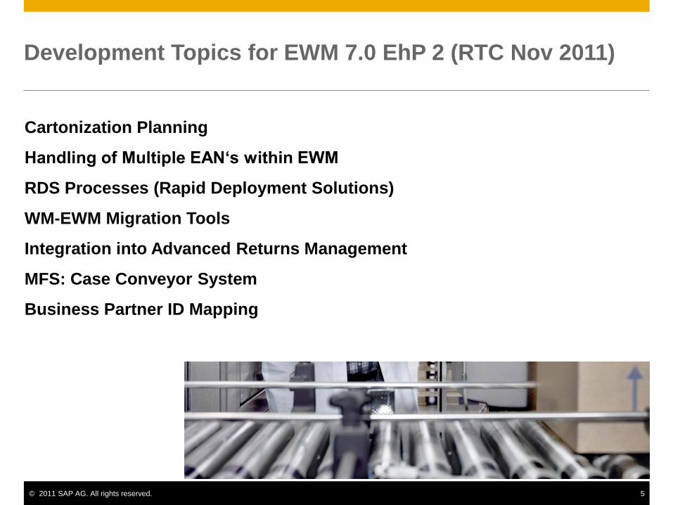
1. Flexible Manufacturing System (FMS)2. Variable Mission Mfg. (VMM)3. Computerized Mfg. System (CMS)
Four-Plan Concept of Manufacturing
CIM System discussed:
Computer Numerical Control (CNC) Direct Numerical Control (DNC) Computer Process Control Computer Integrated Production Management Automated Inspection Methods Industrial Robots etc.
A CIM System consists of the following basic components:
I. Machine tools and related equipmentII. Material Handling System (MHS)III. Computer Control SystemIV. Human factor/labor
CIMS Benefits:
1. Increased machine utilization2. Reduced direct and indirect labor3. Reduce mfg. lead time4. Lower in process inventory5. Scheduling flexibility6. etc.

CIM refers to a production system that consists of:
1. A group of NC machines connected together by2. An automated materials handling system3. And operating under computer control
Why CIMS?In Production Systems
1. Transfer Lines: is very efficient when producing "identical" parts in largevolumes at high product rates.
2. Stand Alone: NC machine: are ideally suited for variations in work partconfiguration.
In Manufacturing Systems:
1. Special Mfg. System: the least flexible CIM system. It is designed to produce a
CIM System
TransferLines
Stand AloneNC Machine
Part Variety (# of different parts)
ProductionVolumn(part/yr)
15,000
15
Part Variety (# of different parts)
ProductionVolumn(part/yr)
15,000
15
SpecialSystem
ManfuacturingCell
FlexibleManufacturingSystem
8001002

very limited number of different parts (2 - 8).2. Mfg. Cell: the most flexible but generally has the lowest number of different parts
manufactured in the cell would be between 40 - 80. Annual production rates roughfrom 200 - 500.
3. Flexible Mfg. System: A typical FMS will be used to process several part familieswith 4 to 100 different part numbers being the usual case.
General FMS
Conventional Approaches to Manufacturing
Conventional approaches to manufacturing have generally centered around machineslaid out in logical arrangements in a manufacturing facility. These machine layoutsare classified by:
1. Function - Machines organized by function will typically perform the samefunction, and the location of these departments relative to each other is normally
arranged so as to minimize interdepartmental material handling. Workpieceproduced in functional layout departments and factories are generally manufacturedin small batches up to fifty pieces (a great variety of parts).
2. Line or flow layout - the arrangement of machines in the part processing order orsequence required. A transfer line is an example of a line layout. Parts progressivelymove from one machine to another in a line or flow layout by means of a rollerconveyor or through manual material handling. Typically, one or very few differentparts are produced on a line or flow type of layout, as all parts processed require thesame processing sequence of operations. All machining is performed in onedepartment, thereby minimizing interdepartmental material handling.

3. Cell - It combines the efficiencies of both layouts into a single multi-functional unit.It referred to as a group technology cell, each individual cell or department iscomprised of different machines that may not be identical or even similar. Each cellis essentially a factory within a factory, and parts are grouped or arranged intofamilies requiring the same type of processes, regardless of processing order.Cellular layouts are highly advantageous over both function and line machinelayouts because they can eliminate complex material flow patterns and consolidatematerial movement from machine to machine within the cell.
Manufacturing Cell
Four general categories:
1. Traditional stand-alone NC machine tool - is characterized as a limited-storage,automatic tool changer and is traditionally operated on a one-to-one machine tooperator ratio. In many cased, stand-alone NC machine tools have been groupedtogether in a conventional part family manufacturing cell arrangement andoperating on a one-to-one or two-to-one or three-to-one machine to operator ratio.
2. Single NC machine cell or mini-cell - is characterized by an automatic workchanger with permanently assigned work pallets or a conveyor-robot arm systemmounted to the front of the machine, plus the availability of bulk tool storage.There are many machines with a variety of options, such as automatic probing,broken tool detection, and high-pressure coolant control. The single NC machinecell is rapidly gaining in popularity, functionality, and affordability.
3. Integrated multi-machine cell - is made up of a multiplicity of metal-cuttingmachine tools, typically all of the same type, which have a queue of parts, eitherat the entry of the cell or in front of each machine. Multi-machine cells are eitherserviced by a material-handling robot or parts are palletized in a two- orthree-machine, in-line system for progressive movement from one machining
station to another.
FMS - sometimes referred to as a flexible manufacturing cell (FMC), is characterizedby multiple machines, automated random movement of palletize parts to and fromprocessing stations, and central computer control with sophisticated command-drivensoftware. The distinguishing characteristics of this cell are the automated flow of rawmaterial to the cell, complete machining of the part, part washing, drying, andinspection with the cell, and removal of the finished part.
I. Machine Tools & Related Equipment
Standard CNC machine tools Special purpose machine tools Tooling for these machines Inspection stations or special inspection probes used with the machine tool
The Selection of Machine Tools1. Part size2. Part shape3. Part variety4. Product life cycle5. Definition of function parts6. Operations other than machining - assembly, inspection etc.
II. Material Handling System
A. The primary work handling system - used to move parts between machine toolsin the CIMS. It should meet the following requirements.
i). Compatibility with computer controlii). Provide random, independent movement of palletized work parts between
machine tools.iii). Permit temporary storage or banking of work parts.iv). Allow access to the machine tools for maintenance tool changing & so on.v). Interface with the secondary work handling systemvi). etc.
B. The secondary work handling system - used to present parts to the individualmachine tools in the CIMS.
i). Same as A (i).ii). Same as A (iii)iii). Interface with the primary work handling systemiv). Provide for parts orientation & location at each workstation for processing.

III. Computer Control System - Control functions of a firm and the supportingcomputing equipment
Control Loop of a Manufacturing System

IV. Functions of the computer in a manufacturing organization
V. Functions of Computer in CIMS1. Machine Control –CNC
NCProgramming
Micro Computer(Software Function
&NC Program Storage)
Feedback
MachineCenter
Hardware(interface
&Servo)

2. Direct Numerical Control (DNC) - A manufacturing system in which a number ofm/c are controlled by a computer through direct connection & in real time.
Consists of 4 basic elements:
Central computer Bulk memory (NC program storage) Telecommunication line Machine tools (up to 100)
3. Production Control - This function includes decision on various parts onto thesystem.
Decision are based on: red production rate/day for the various parts Number of raw work parts available Number of available pallets
4. Traffic & Shuttle Control - Refers to the regulations of the primary & secondarytransportation systems which moves parts between workstation.
5. Work Handling System Monitoring - The computer must monitor the status ofeach cart & /or pallet in the primary & secondary handling system.
6. Tool Control Keeping track of the tool at each station Monitoring of tool life
7. System Performance Monitoring & Reporting - The system computer can beprogrammed to generate various reports by the management on systemperformance.
Utilization reports - summarize the utilization of individual workstation as wellas overall average utilization of the system.
Production reports - summarize weekly/daily quantities of parts produced froma CIMS (comparing scheduled production vs. actual production)
Status reports - instantaneous report "snapshot" of the present conditions of theCIMS.
Tool reports - may include a listing of missing tool, tool-life status etc.
Central
Computer
Bulk memory(NC Program)
Satellit
MinicomputerBulk
memory
m/c m/c
sends instructions & relieves data (ethernet)
Tele-Communication Lines
Up to 100 m/c tools

8. Manufacturing data base
Collection of independent data bases Centralized data base Interfaced data base Distributed data base
Production StrategyThe production strategy used by manufacturers is based on several factors; the twomost critical are customer lead time and manufacturing lead time.Customer lead time identifies the maximum length of time that a typical customer iswilling to wait for the delivery of a product after an order is placed.Manufacturing lead time identifies the maximum length of time between the receipt ofan order and the delivery of a finished product.Manufacturing lead time and customer lead time must be matched. For example,when a new car with specific options is ordered from a dealer, the customer is willingto wait only a few weeks for delivery of the vehicle. As a result, automotivemanufacturers must adopt a production strategy that permits the manufacturinglead-time to match the customer's needs.The production strategies used to match the customer and manufacturer lead times aregrouped into four categories:
1. Engineer to order (ETO)2. Make to order (MTO)3. Assemble to order (ATO)4. Make to stock (MTS)
Engineer to OrderA manufacturer producing in this category has a product that is either in the first stageof the life-cycle curve or a complex product with a unique design produced insingle-digit quantities. Examples of ETO include construction industry products(bridges, chemical plants, automotive production lines) and large products withspecial options that are stationary during production (commercial passenger aircraft,ships, high-voltage switchgear, steam turbines). Due to the nature of the product, thecustomer is willing to accept a long manufacturing lead time because the engineeringdesign is part of the process.
Make to OrderThe MTO technique assumes that all the engineering and design are complete and theproduction process is proven. Manufacturers use this strategy when the demand is

unpredictable and when the customer lead-time permits the production process to starton receipt of an order. New residential homes are examples of this production strategy.Some outline computer companies make personal computer to customer specifications,so they followed MTO specifications.
Assemble to OrderThe primary reason that manufacturers adopt the ATO strategy is that customer leadtime is less than manufacturing lead time. An example from the automotive industrywas used in the preceding section to describe this situation for line manufacturingsystems. This strategy is used when the option mix for the products can be forecaststatistically: for example, the percentage of four-door versus two-door automobilesassembled per week. In addition, the subassemblies and parts for the final product arecarried in a finished components inventory, so the final assembly schedule isdetermined by the customer order. John Deere and General Motors are examples ofcompanies using this production strategy.
Make to StockMTS, is used for two reasons: (1) the customer lead time is less than themanufacturing lead time, (2) the product has a set configuration and few options sothat the demand can be forecast accurately. If positive inventory levels (the store shelfis never empty) for a product is an order-winning criterion, this strategy is used. Whenthis order-winning criterion is severe, the products are often stocked in distributionwarehouses located in major population centers. This option is often the last phase ofa product's life cycle and usually occurs at maximum production volume.
Manufacturing Enterprise (Organization) In most manufacturing organizations the functional blocks can be found as: A CIM implementation affects every part of an enterprise; as a result, every
block in the organizational model is affected.

Sales and Promotion The fundamental mission of sales and promotion (SP) is to create customers.To achieve this goal, nine internal functions are found in many companies: sales,customer service, advertising, product research and development, pricing,packaging, public relations, product distribution, and forecasting.
sales and promotion interfaces with several other areas in the business: The customer services interface supports three major customer functions:
order entry, order changes, and order shipping and billing. The order changeinterface usually involves changes in product specifications, change inproduct quantity (ordered or available for shipment), and shipment dates andrequirements.
Sales and marketing provide strategic and production planning information tothe finance and management group, product specification and customerfeedback information to product design, and information for masterproduction scheduling to the manufacturing planning and control group.
Product/Process Definition Engineering The unit includes product design, production engineering, and engineering
release. The product design provides three primary functions: (1) product design and
conceptualization, (2) material selection, and (3) design documentation. The production engineering area establishes three sets of standards: work,
process, and quality. The engineering release area manages engineering change on every
production part in the enterprise. Engineering release has the responsibility ofsecuring approvals from departments across the enterprise for changes madein the product or production process.
Manufacturing Planning and Control (MPC) The manufacturing planning and control unit has a formal data and
information interface with several other units and departments in theenterprise.
The MPC unit has responsibility for:1. Setting the direction for the enterprise by translating the management
plan into manufacturing terms. The translation is smooth iforder-winning criteria were used to develop the management plan.
2. Providing detailed planning for material flow and capacity to supportthe overall plan.
3. Executing these plans through detailed shop scheduling and purchasingaction.
MPC Model for Information Flow

Shop Floor Shop floor activity often includes job planning and reporting, material
movement, manufacturing process, plant floor control, and quality control. Interfaces with the shop floor unit are illustrated.
Support Organization The support organizations, indicated vary significantly from firm to firm. The functions most often included are security, personnel, maintenance,
human resource development, and computer services. Basically, the support organization is responsible for all of the functions not
provided by the other model elements.Production Sequence :one possibility for the flow required to bring a product to acustomer