
INTRODUCTION TO COLUMN ANALOGY METHOD306 THEORY OF INDETERMINATE STRUCTURES . CHAPTER SEVEN . 7....
44
306 THEORY OF INDETERMINATE STRUCTURES CHAPTER SEVEN 7. INTRODUCTION TO COLUMN ANALOGY METHOD The column analogy method was also proposed by Prof. Hardy Cross and is a powerful technique to analyze the beams with fixed supports, fixed ended gable frames, closed frames & fixed arches etc., These members may be of uniform or variable moment of inertia throughout their lengths but the method is ideally suited to the calculation of the stiffness factor and the carryover factor for the members having variable moment of inertia. The method is strictly applicable to a maximum of 3rd degree of indeterminacy. This method is essentially an indirect application of the consistent deformation method. The method is based on a mathematical similarity (i.e. analogy) between the stresses developed on a column section subjected to eccentric load and the moments imposed on a member due to fixity of its supports. *(We have already used an analogy in the form of method of moment and shear in which it was assumed that parallel chord trusses behave as a deep beam). In the analysis of actual engineering structures of modern times, so many analogies are used like slab analogy, and shell analogy etc. In all these methods, calculations are not made directly on the actual structure but, in fact it is always assumed that the actual structure has been replaced by its mathematical model and the calculations are made on the model. The final results are related to the actual structure through same logical engineering interpretation. In the method of column analogy, the actual structure is considered under the action of applied loads and the redundants acting simultaneously on a BDS. The load on the top of the analogous column is usually the B.M.D. due to applied loads on simple spans and therefore the reaction to this applied load is the B.M.D. due to redundants on simple spans considers the following fixed ended loaded beam. (d) Loading on top of analogous column, Ms diagram, same as(b). L 1 (Unity) (e) X-section of analogous column. (f) Pressure on bottom of analogous column, Mi diagram. E =Constt. I (a) Given beam under loads Ma M B A P 1 P 2 B L 0 0 0 0 M B M A (c) B.M.D. due to redundants,plotted on the compression side on simple span (b) B.M.D. due to applied loads, plotted on the compressin side. WKN/m on simple span Ma Mb
Transcript of INTRODUCTION TO COLUMN ANALOGY METHOD306 THEORY OF INDETERMINATE STRUCTURES . CHAPTER SEVEN . 7....

306 THEORY OF INDETERMINATE STRUCTURES
CHAPTER SEVEN
7. INTRODUCTION TO COLUMN ANALOGY METHOD
The column analogy method was also proposed by Prof. Hardy Cross and is a powerful technique to analyze the beams with fixed supports, fixed ended gable frames, closed frames & fixed arches etc., These members may be of uniform or variable moment of inertia throughout their lengths but the method is ideally suited to the calculation of the stiffness factor and the carryover factor for the members having variable moment of inertia. The method is strictly applicable to a maximum of 3rd degree of indeterminacy. This method is essentially an indirect application of the consistent deformation method.
The method is based on a mathematical similarity (i.e. analogy) between the stresses developed on a column section subjected to eccentric load and the moments imposed on a member due to fixity of its supports. *(We have already used an analogy in the form of method of moment and shear in which it was assumed that parallel chord trusses behave as a deep beam). In the analysis of actual engineering structures of modern times, so many analogies are used like slab analogy, and shell analogy etc. In all these methods, calculations are not made directly on the actual structure but, in fact it is always assumed that the actual structure has been replaced by its mathematical model and the calculations are made on the model. The final results are related to the actual structure through same logical engineering interpretation.
In the method of column analogy, the actual structure is considered under the action of applied loads and the redundants acting simultaneously on a BDS. The load on the top of the analogous column is usually the B.M.D. due to applied loads on simple spans and therefore the reaction to this applied load is the B.M.D. due to redundants on simple spans considers the following fixed ended loaded beam.
(d) Loading on top of analogous column, Ms diagram, same as(b).
L
1 (Unity)
(e) X-section of analogous column.
(f) Pressure on bottom of analogous column, Mi diagram.
E =Constt.I(a) Given beam under loads
Ma MBA
P1 P2
BL
0 0
00
MBMA (c) B.M.D. due to
redundants,
plottedon
the
compression
side on simple span
(b) B.M.D. due toapplied loads,plotted on thecompressin side.
WKN/m
on simple span
MaMb

COLUMN ANALOGY METHOD 307
The resultant of B.M.D’s due to applied loads does not fall on the mid point of analogous column section which is eccentrically loaded. Msdiagram = BDS moment diagram due to applied loads. Mi diagram = Indeterminate moment diagram due to redundants. If we plot (+ve) B.M.D. above the zero line and (−ve) B.M.D below the zero line (both on compression sides due to two sets of loads) then we can say that these diagrams have been plotted on the compression side. (The conditions from which MA & MB can be determined, when the method of consistent deformation is used, are as follows). From the Geometry requirements, we know that (1) The change of slope between points A & B = 0; or sum of area of moment diagrams between
A & B = 0 (note that EI = Constt:), or area of moment diagrams of fig.b = area of moment diagram of fig..c.
(2) The deviation of point B from tangent at A = 0; or sum of moment of moment diagrams between A
& B about B = 0, or Moment of moment diagram of fig.(b) about B = moment of moment diagram of fig.(c) about B. Above two requirements can be stated as follows.
(1) Total load on the top is equal to the total pressure at the bottom and; (2) Moment of load about B is equal to the moment of pressure about B), indicates that the analogous column is on equilibrium under the action of applied loads and the redundants. 7.1. SIGN CONVENTIONS:−
It is necessary to establish a sign convention regarding the nature of the applied load (Ms − diagram) and the pressures acting at the base of the analogous column (Mi−diagram.) 1. Load ( P) on top of the analogous column is downward if Ms/EI diagram is (+ve) which means that
it causes compression on the outside or (sagging) in BDS vice-versa. If EI is constant, it can be taken equal to units.
Inside
Outside
CT
2. Upward pressure on bottom of the analogous column ( Mi − diagram) is considered as (+ve). 3. Moment (M) at any point of the given indeterminate structure ( maximum to 3rd degree) is given by
the formula.
M = Ms − Mi, which is (+ve) if it causes compression on the outside of members.
308 THEORY OF INDETERMINATE STRUCTURES
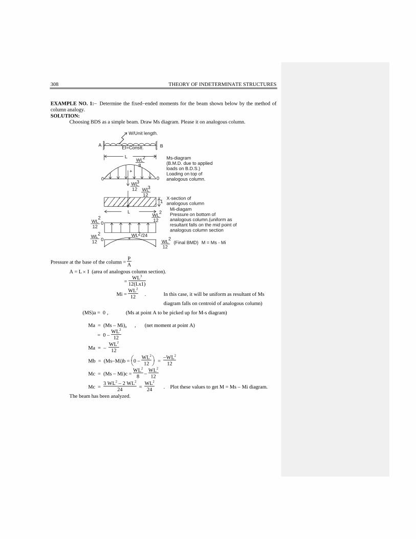
EXAMPLE NO. 1:− Determine the fixed−ended moments for the beam shown below by the method of column analogy. SOLUTION: Choosing BDS as a simple beam. Draw Ms diagram. Please it on analogous column.
A
W/Unit length.
B
L
EI=Constt.
2WL8
WL12 WL
12
+0 0
Ms-diagram(B.M.D. due to appliedloads on B.D.S.)Loading on top ofanalogous column.3
3
L
1X-section ofanalogous column
0
0
WL12
2
WL12
2
WL12
2
WL12
2WL2/24
+
Mi-diagamPressure on bottom ofanalogous column.(uniform asresultant falls on the mid point of analogous column section
(Final BMD) M = Ms - Mi
Pressure at the base of the column = PA
A = L × I (area of analogous column section).
= WL3
12(Lx1)
Mi = WL2
12 . In this case, it will be uniform as resultant of Ms
diagram falls on centroid of analogous column)
(MS)a = 0 , (Ms at point A to be picked up for M-s diagram) Ma = (Ms − Mi)a , (net moment at point A)
= 0 − WL2
12
Ma = − WL2
12
Mb = (Ms−Mi)b =
0 −
WL2
12 = −WL2
12
Mc = (Ms − Mi)c = WL2
8 − WL2
12
Mc = 3 WL2 − 2 WL2
24 = WL2
24 . Plot these values to get M = Ms − Mi diagram.
The beam has been analyzed.
COLUMN ANALOGY METHOD 309
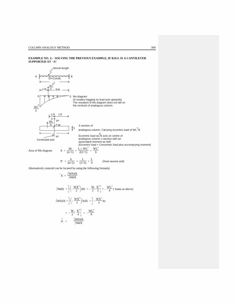
EXAMPLE NO. 2:- SOLVING THE PREVIOUS EXAMPLE, IF B.D.S. IS A CANTILEVER SUPPORTED AT ‘A’.
A BEI=Constt.
L
00 Ms-diagram(It creates hagging so load acts upwards)The resultant of Ms diagram does not fall onthe centroid of analogous column.
L/4 L/2
L/4 3/4L
Lyo
M
yo
W L6
WL6
3
3
WL2
2
X-section ofanalogous column. Carrying eccentric load of WL /6
3
Eccentric load wL3/6 acts on centre of
analogous column x-section with an associated moment as well(Eccentric load = Concentric load plus accomprying moment)
W/unit-length
1
Centroidal axis
Area of Ms diagram A = bh
(n+1) = L × WL2
2(2+1) = WL3
6
X′ = b
(n+2) = L
(2+2) = L4 (from nearest and)
Alternatively centroid can be located by using the following formula)
X = ∫ MXdX∫ MdX
∫ MdX = L
∫o
−
WX2
2 dX = − W2
X3
3 L|o = −
WL3
6 ( Same as above)
∫ MXdX = L
∫o
−
WX2
2 XdX = L
∫o −
WX3
2 dx
= − W2
X4
4 L|o = −
WL4
8
X−
= ∫ MXdX∫ MdX
310 THEORY OF INDETERMINATE STRUCTURES
X−
= − WL4
8 × 6
(−WL3) = 34 L. (from the origin of moment
expression or from farthest end) NOTE : Moment expression is always independent of the variation of inertia. Properties of Analogous Column X−section :− 1. Area of analogous column section, A = L × 1 = L
2. Moment of inertia, I yo yo = L 3
12
3. Location of centroidal column axis, C = L2
A e’=M =
WL3
6
L
4 = WL4
24 , ( L4 is distance between axis yo− yo and the centroid of Ms diagram
where the load equal to area of Ms diagram acts.)
(Mi)a = PA ±
McI (P is the area of Ms diagram and is acting upwards so negative
C = L2 and I =
L3
12 )
= −WL3
6 . L − WL4 . L . 12
24 . 2 . L3 (Load P on analogous column is negative)
= − WL2
6 − WL2
4 ( Reaction due to MC/I would be having the same
direction at A as that due to P while at B these
= −2WL2 − 3 WL2
12 two would be opposite)
= − 512 WL2
(Ms)a = − WL2
2
Ma = (Ms − Mi)a
= − WL2
2 + 5
12 WL2
= − 6 WL2 + 5 WL2
12
Ma = − WL2
12
COLUMN ANALOGY METHOD 311
Mb = (Ms − Mi)b
(Mi)b = PA ±
McI
= − WL3
6 × L + WL4 × L × 12
24 × 2 × L3
= −WL2
6 + WL2
4
= − 2WL2 + 3 WL2
12
= WL2
12
(Ms)b = 0
Mb = (Ms − Mi)b = 0 − WL2
12 = − WL2
12
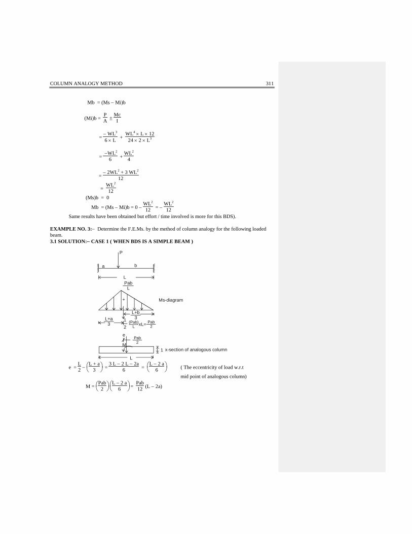
Same results have been obtained but effort / time involved is more for this BDS). EXAMPLE NO. 3:− Determine the F.E.Ms. by the method of column analogy for the following loaded beam. 3.1 SOLUTION:− CASE 1 ( WHEN BDS IS A SIMPLE BEAM )
P
ba
LPab
L
+
L+a3
L+b3
Pab2
12
(Pab)L
Pab2xL=
e
M
L
1
Ms-diagram
x-section of analogous column
e = L2 −
L + a
3 = 3 L − 2 L − 2a
6 =
L − 2 a
6 ( The eccentricity of load w.r.t
mid point of analogous column)
M =
Pab
2
L − 2 a
6 = Pab12 (L − 2a)
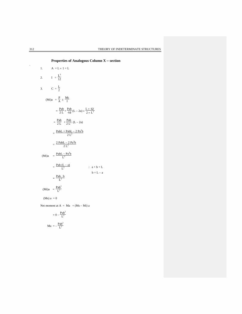
312 THEORY OF INDETERMINATE STRUCTURES
Properties of Analogous Column X − section . 1. A = L × 1 = L
2. I = L3
12
3. C = L2
(Mi)a = PA ±
McI
= Pab2 L +
Pab 12 (L − 2a) ×
L × 12 2 × L3
= Pab2 L +
Pab2 L2 (L − 2a)
= PabL + PabL − 2 Pa2b
2 L2
= 2 PabL − 2 Pa2b
2 L2
(Mi)a = PabL − Pa2b
L2
= Pab (L − a)
L2 ∴ a + b = L
b = L − a
= Pab . b
L2
(Mi)a = Pab2
L2
(Ms) a = 0 Net moment at A = Ma = (Ms − Mi) a
= 0 − Pab2
L2
Ma = − Pab2
L2

COLUMN ANALOGY METHOD 313
The (−ve) sign means that it gives us tension at the top when applied at A.
(Mi)b = PA ±
MCI
= Pab2L −
Pab12L2 (L − 2a) ×
L × 122 × L3
= Pab2L −
Pab2L2 (L − 2a)
= PabL − PabL + 2Pa2b
2L2
= 2Pa2b2L2
(Mi)b = Pa2bL2
(Ms)b = 0
Mb = (Ms − Mi)a = 0 − Pa2bL2
Mb = − Pa2b
L2
The minus sign means that it gives us tension at the top. EXERCISE 3.2:- If B.D.S. is a cantilever supported at A:− We solve the same exercise 3.1 but with a different BDS.
A a b
P
BL
EI=Constt
0 0
Pa
e Pa2
2
M
LL/2
1
22Pa
12 Pa(a) =
Ms-diagram (load equal to area ofMs diagram acts upwards)
The upper eccentric load has been nowplaced on centroid axis of analogous columnsection plus accompaying moment.
x-section of analogous column underload and accompaying moment at columncentroidal aixis.
L2
a3

314 THEORY OF INDETERMINATE STRUCTURES
e = L2 −
a3 =
3L − 2a
6
Pe = M = Pa2
2
3L − 2a
6 = Pa2 (3L − 2a)
12
Properties of Analogous Column section :− A = L , I = L3
12 , C = L2
(Mi)a = PA ±
MCI
= − Pa2
2L − Pa2 (3L − 2a) . L . 12
12 . 2 . L3 (Due to upward P= Pa2/2, reaction at A
and B is downwards while due to moment,
= − Pa2
2L − Pa2 (3L − 2a)
2L2 reaction at B is upwards while at A it is
downwards. Similar directions will have
= −Pa2L − 3Pa2L + 2Pa3
2L2 the same sign to be additive or vice−versa)
= −4 Pa2L + 2Pa3
2L2
= −2Pa2L + Pa3
L2
= Pa2 (a − 2L)
L2
= −Pa2 (2L − a)
L2 , We can write 2L − a = L + L − a = L + b
(Mi)a = −Pa2 (L + b)
L2
(Ms)a = − Pa Ma = (Ms − Mi)a
= −Pa + Pa2(L + b)
L2
= − PaL2 + Pa2 L + Pa2b
L2

COLUMN ANALOGY METHOD 315
= − PaL (L − a) + Pa2 b
L2
= − PabL + Pa2 b
L2
= − Pab (L − a)
L2
= − Pab . b
L2
Ma = − Pab2
L2 ( Same result as was obtained with a different BDS)
(Mi)b = PA ±
MCI
= − Pa2
2L + Pa2 (3L − 2a)
2L2
= − Pa2 L + 3Pa2L − 2Pa3
2L2
= 2 Pa2 L − 2Pa3
2L2
= Pa2 L − Pa3
L2
= +Pa2 (L − a )
L2
(Mi)b = Pa2 b
L2
(Ms)b = 0 Mb = (Ms − Mi)b
= 0 − Pa2 b
L2
Mb = − Pa2 b
L2 ( Same result as obtained with a different BDS)
316 THEORY OF INDETERMINATE STRUCTURES
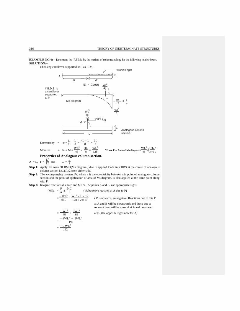
EXAMPLE NO.4:− Determine the F.F.Ms. by the method of column analogy for the following loaded beam. SOLUTION:− Choosing cantilever supported at B as BDS.
L8
A B
L/2 L/2
w/unit length
E = ConsttI
0
If B.D.S. is a cantileversupported at b.
0
WL48
WL48
3
3
= WL2
x L4
WL8
2
M3/8 L
1
LAnalogous columnsection.
e=
Ms-diagram
Eccentricity = e = L2 −
L8 =
4L − L8 =
3L8
Moment = Pe = M = WL3
48 × 3L8 =
WL4
128 Where P = Area of Ms diagram=WL3
48 =
bh
n+1
Properties of Analogous column section. A = L, I =
L3
12 and C = L2
Step 1: Apply P= Area Of BMD(Ms diagram ) due to applied loads in a BDS at the center of analogous column section i.e. at L/2 from either side.
Step 2: The accompanying moment Pe, where e is the eccentricity between mid point of analogous column section and the point of application of area of Ms diagram, is also applied at the same point along with P.
Step 3: Imagine reactions due to P and M=Pe. At points A and B, use appropriate signs.
(Mi)a = PA ±
MCI ( Subtractive reaction at A due to P)
= − WL3
48.L + WL4 × L × 12128 × 2 × L3 ( P is upwards, so negative. Reactions due to this P
at A and B will be downwards and those due to moment term will be upward at A and downward
= − WL2
48 + 3WL2
64 at B. Use opposite signs now for A)
= − 4WL2 + 9WL2
192
= + 5 WL2
192

COLUMN ANALOGY METHOD 317
(Ms)a = 0 ( Inspect BMD drawn on simple determinate span) Ma = (Ms − Mi)a
= 0 − 5WL2
192
Ma = − 5WL2
192
(Mi)b = PA ±
MCI ( Additive reactions at B as use negative sign with
McI term)
= − 4WL2 − 9WL2
192
= − 13 WL2
192
(Ms)b = − WL2
8
Mb = (Ms − Mi)b
= − WL2
8 + 13 WL2
192 =
−24 WL2 + 13 WL2
192
Mb = −11192 WL2
The beam is now statically determinate etc. EXAMPLE NO. 5:− Determine the F.E. M’s by the method of column analogy for the following loaded beam. SOLUTION:−
A= bh
n+1
= WL4 192
X= b
n+2
=
L
2(3+2)
X= L
10
AL/2 L/2
B
EI=Constt:WL192
WL192
L10 00
eM
4
L
1xWxL 2 2
x L 3
(L) 2
= WL 24
3
1
W/Unit length
Analogous column section
Ms-diagram ( )
4
WL3
24
L 2 x
A = 4
e = L2 −
L10 =
5L − L10 =
4L10 =
25 L
M =
WL4
192 ×
2 L
5 = WL5
480
Comment [A1]:

318 THEORY OF INDETERMINATE STRUCTURES
Properties of Analogous column section.
A = L , I = L3
12, C = L2
(Mi)a = PA ±
MCI
(Mi)a = − WL4
192L + WL5 × L × 12480 × 2 × L3 (Downward reaction at A due to P and upward reaction at A due to M)
= − WL3
192 + WL3
80
= − 80WL3 + 192 WL3
15360
= 112 WL3
15360 ( Divide by 16)
(Mi)a = 7 WL3
960
(Ms)a = 0 Ma = (Ms − Mi)a
Ma = 0 − 7
960 WL3 = − 7960 WL3
(Mi)b = PA ±
MCI
= − WL3
192 − WL3
80
= − 80 WL3 − 192 WL3
15360
= − 272 WL3
15360
= − 17 WL3
960
(Ms)b = − WL3
24
Mb = (Ms − Mi) b
COLUMN ANALOGY METHOD 319
= − WL3
24 + 17
960 WL3
= − 40 WL3 + 17 WL3
960
Mb = − 23 WL3
960
Note : After these redundant end moments have been determined, the beam is statically
determinate and reactions , S.F, B.M, rotations and deflections anywhere can be found.
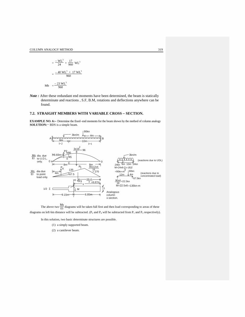
7.2. STRAIGHT MEMBERS WITH VARIABLE CROSS − SECTION. EXAMPLE NO. 6:− Determine the fixed−end moments for the beam shown by the method of column analogy SOLUTION:__ BDS is a simple beam.
3kn/m90kn
4mBA
6m 10m
3x168b90P2
3.83mMsEI
dia. dueto U.D.L.only. 0 a
= 96
0
3kn/m
6m 10m 24kn24knM=24x6-3 x (6)2=90kn-m2
12m90kn4m
67.5kn90x416
=22.5kn
1M=22.5x6 =135kn-m
Analogouscolumnx-section.
6.85m9.15m
1/2
yo P3x
4m
P48m 8m
P1 90x12x416= 270
67.5
16+43 =6.67m
dia dueto pointload only.
MsEI
2I=2 I=1
M
45
135
C0 (reactions due to UDL)
(reactions due toconcentrated load)
The above two MsEI diagrams will be taken full first and then load corresponding to areas of these
diagrams on left 6m distance will be subtracted. (P2 and P4 will be subtracted from P1 and P3 respectively). In this solution, two basic determinate structures are possible.
(1) a simply supported beam.
(2) a cantilever beam.

320 THEORY OF INDETERMINATE STRUCTURES
This problem is different from the previous one in the following respects. (a) Ms − diagram has to be divided by a given value of I for various portions of span. (b) The thickness of the analogous column X − section will also vary with the variation of
inertia. Normally, the width 1/EI can be set equal to unity as was the case in previous problem, when EI was set equal to unity.
(c) As the dimension of the analogous column X − section also varies in this case, we will have
to locate the centroidal axis of the column and determine its moment of inertia about it. (1) SOLUTION:- By choosing a simple beam as a B.D.S.
P1 = 23 × 16 × 96 = 1024 KN ( Load corresponding to area of entire BMD due to UDL)
∫ MdX = 6
∫o (24X − 1.5 X2) dX (Simply supported beam moment due to UDL of left 6/ portion)
= 12X2 − 0.5X3 6|o = 12 × 36 − 0.5 × 216 = 432 − 108 = 324
area of abc = 324
∫ MXdX = 6
∫o (24X − 1.5X2) XdX
= 6
∫o (24X2 − 1.5X3) dX
= 243 X3 −
1.54 X4
6|o = 8 × 63 −
1.54 × 64
= 1242
X = ∫ MxdX∫ MdX =
1242342 = 3.83 m from A. (of left 6/ portion of BMD)
P2 = 12 ( area abc) =
3242 = 162 KN( To be subtracted from Ms diagram )
P3 =
12 × 16 × 270 = 2160 KN ( Area of BMD due to concentrated Load)
P4 =
12 × 6 × 67.5 = 202.5 KN ( To be subtracted from Ms diagram )

COLUMN ANALOGY METHOD 321
Properties of Analogous column x − section.
Area = A = 1 × 10 + 12 × 6 = 13 m2
X = ∫XdA
A = (1 × 10) 5 + (1/2 × 6 × 13)
13 from R.H.S.
= 6.85 m ( From point B) . It is the location of centroidal axis Yo−Yo.
Iy0 y0 = 1 × 10³
12 + 10(1.85)2 + 0.5 × 63
12 + (0.5 × 6) × (6.15)2 = 240 m4
by neglecting the contribution of left portion about its own centroidal axis. Total load to be applied at the centroid of analogous column x − section. = P1 + P3 − P2 − P4
= 1024 + 2160 − 162 − 202.5 = 2819.5 KN Applied Moment about centroidal axis = M = + 1024 (1.15) − 2160 (0.18) − 162 (5.32) − 202.5 (5.15) = − 1116 KN−m , clockwise (Note: distance 5.32 = 9.15 − 3.83 (and 5.15 = 9.15 − 4) The (−ve) sign indicates that the net applied moment is clockwise.
(Mi)a = PA ±
MCI ( subtractive reactions at A)
= 2819.5
13 − 1116 × 9.15
240 , (Preserve at A due to McI is downwards so negative).
= + 174.34 KN−m (Ms)a = 0 Ma = (Ms − Mi)a = 0 − 174.34 = − 174.34 KN−m
(Mi)b = 2819.5
13 + 1116 × 6.85
240 , ( Note the difference in the values of C for points A and B.)
= + 248.74 KN−m
(Ms)b = 0
Mb = (Ms − Mi)b
= 0 − 248.74
= − 248.74 KN−m
The −ve sign with Ma & Mb indicates that these cause compression on the inside when applied of these points.

322 THEORY OF INDETERMINATE STRUCTURES
EXAMPLE NO.7:− Determine the F.E.Ms. by the method of column analogy. SOLUTION:−
1. Choosing a simple beam as a B.D.S.
A IC B
90kn
4m3kn/m
2 CI3m 6m
1.95
m
P2 P3
2.58
6.5 mf
P1
2.25
a
3x132
8 =63.45445
m
e
P5 2m
83
41.5124.62
P62.67
mdiagram due to point load.
diagram due to U.D.L.
MsEI
MsEI
3KN/m
19.5
13m
19.5
yo
yo
1/2 Analogous columnx-section
x877.6kn-m
175.9knP4
6.66m6.34m
1
90x9x413 =249.23
(13+4)3 =5.67m
b d
½
2 CI
c
27
249.23
(BDS under UDL)
(M3)L = 19.5 × 3 − 1.5(3)2 = 45 KN−m ( 3m from A )
(M4)R = 19.5 × 4 − 32 (4)2 = 54 KN−m ( 4m from B)
90
4m9m27.69 62.307
(BDS under point load)
(M3)L = 27.69 × 3 = 83 KN−m ( 3m from A) ( M4)R = 62.307 × 4 = 249.22 (4m from B)
∫ MdX = area abc = 3
∫o (19.5 X − 1.5 X2) dX

COLUMN ANALOGY METHOD 323
= 19.5
2 X2 − 1.53 X3
3|o = 74.25
∫ MXdX = 3
∫o (19.5 X2 − 1.5 X3) dX =
19.53 X3 −
1.54 X4
3|o
= 145.12
X = 145.1274.25 = 1.95.m ( From point A as shown )
Area def = ∫ MdX = 4
∫o (19.5X − 1.5 x2) dX = 124
∫ MXdX = 4
∫o (19.5 X2 − 1.5 x3) dX
= 19.5X3
3 − 1.54 X4
4|o
= 320
X = 320124 = 2.58 m ( From point B )
P1 = 23 × 63.4 × 13 = 549.5 KN( Due to entire BMD due to UDL )
P2 = 12 (area abc) =
12 (74.25) = 37.125 KN ( To be subtracted )
P3 = 12 (area def) =
12 (124) = 62 KN ( To be subtracted )
P4 = 12 × 249.23 × 13 = 1620 KN ( Entire area of BMD due to point load)
P5 = 12 × 41.5 × 3 = 62.25 KN ( To be subtracted )
P6 = 12 × 4 × 124.62 = 249.23 KN ( To be subtracted )

324 THEORY OF INDETERMINATE STRUCTURES
Properties of Analogous column x − section.
A = 12 × 4 + 1 × 6 +
12 × 3 = 9.5m2
X = (0.5 × 4) × 2 + (1 × 6) × 7 + (0.5 × 3) × (11.5)
9.5
X = 6.66 ( From point B) meters
Iyoyo = 0.5 × 43
12 + (0.5 × 4)(4.68)2 + 1 × 63
12 + (1 × 6)(0.34)2
+ 0.5 × 32
12 + (1.5)(4.84)2
= 101.05 Total concentric load on analogous column x – section to be applied at centroidal column axis ) P = P1 − P2 − P3 + P4 − P5 − P6 = 549.5 − 37.125 − 62 + 1620 − 62.25 − 249.23 = 1759 KN Total applied moment at centroid of analogous column due to above six loads is = 549.5 (0.16) + 37.125 (4.39) − 62(4.08) + 1620 (0.99) + 62.25 (4.34) − 249.2 (3.99) = + 877.6 clockwise.
(Mi)a = PA ±
MCI ( Reactions due to P and M are subtractive at A)
= 17599.5 −
877.6 × 6.34101.05
= + 130 KN−m (Ms)a = 0 Ma = (Ms − Mi)a = 0 − 130 = − 130 KN−m
(Mi)b = PA ±
MCI
= 17599.5 +
877.6 × 6 × 6.66101.05 ( Reactions due to P and M are additive at B)
= + 243 KN−m (Ms)b = 0
COLUMN ANALOGY METHOD 325
Mb = (Ms − Mi)b = 0 − 243
Mb = − 243 KN−m Now the beam has become determinate. EXAMPLE NO. 7:- (2) Choosing cantilever supported at B as a B.D.S. Let us solve the loaded beam shown below again.
P3=
A
3KN/m 90KN
B
3m 6m 4m
P1=1098.53.25m
fa2.25m
b
d
60.79
P2=6.75
13.5
e121.5126.75
g
3x 13x13/2
=253.5367
1.33m
180360
1.33mPs=360KN
1/2
1/2
6.66myo
yo
6.34m
1089.75Kn
3894KN-m
A =
bhn+113x253.5
3=1098.5
=
A= bhn+1 = 4x360
2 =720
X' = bn+2
= 134 =3.25
X' = bn+2
= 43 =1.33
3KN/m 4m
B
253.5
10m
39
3m
A
1
C
Analogous column section
Ms/EI diagram due to point load
Ms/EI diagram due to u.d.l(2nd degree curve)
P4 = 720
2I I 2I
BDS under UDL
P1
P4=
Area abc = ∫ MdX = 3
∫o
−
32 X2 dX
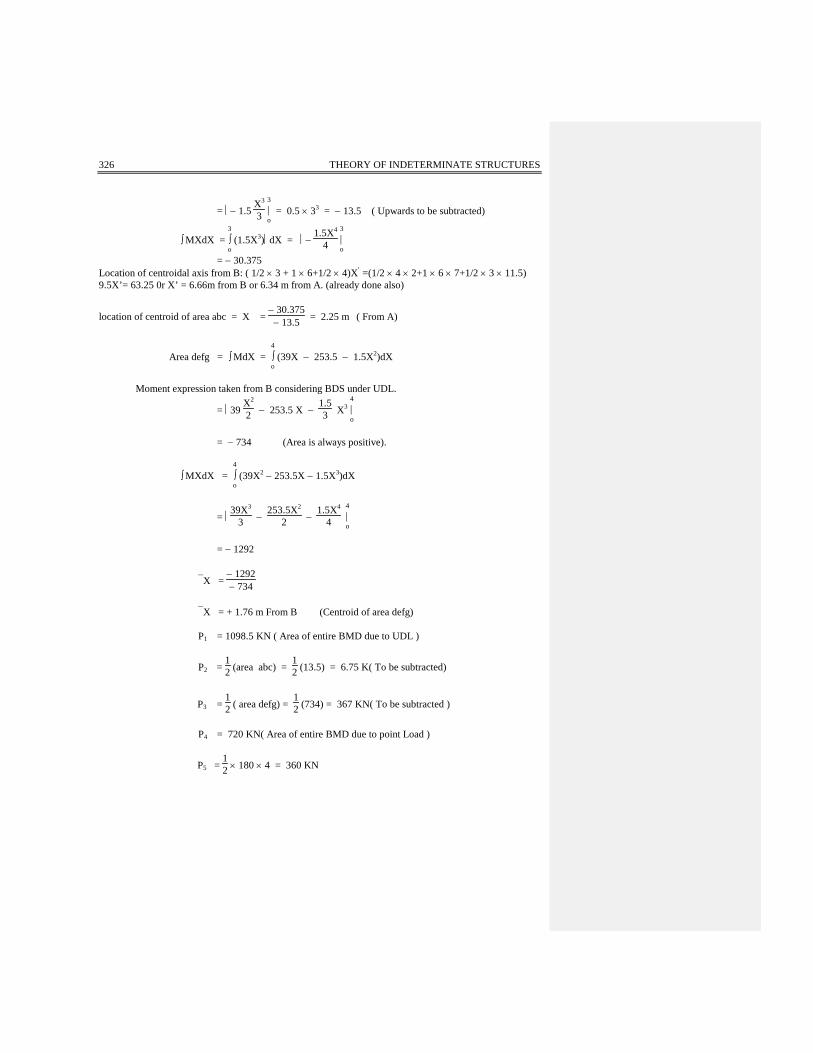
326 THEORY OF INDETERMINATE STRUCTURES
= − 1.5 X3
3 3|o = 0.5 × 33 = − 13.5 ( Upwards to be subtracted)
∫ MXdX = 3
∫o (1.5X3)dX = −
1.5X4
4 3|o
= − 30.375 Location of centroidal axis from B: ( 1/2 × 3 + 1 × 6+1/2 × 4)X′ =(1/2 × 4 × 2+1 × 6 × 7+1/2 × 3 × 11.5) 9.5X’= 63.25 0r X’ = 6.66m from B or 6.34 m from A. (already done also)
location of centroid of area abc = X = − 30.375
− 13.5 = 2.25 m ( From A)
Area defg = ∫ MdX = 4
∫o (39X − 253.5 − 1.5X2)dX
Moment expression taken from B considering BDS under UDL.
= 39 X2
2 − 253.5 X − 1.53 X3
4|o
= − 734 (Area is always positive).
∫ MXdX = 4
∫o (39X2 − 253.5X − 1.5X3)dX
= 39X3
3 − 253.5X2
2 − 1.5X4
4 4|o
= − 1292
X = − 1292− 734
X = + 1.76 m From B (Centroid of area defg) P1 = 1098.5 KN ( Area of entire BMD due to UDL )
P2 = 12 (area abc) =
12 (13.5) = 6.75 K( To be subtracted)
P3 = 12 ( area defg) =
12 (734) = 367 KN( To be subtracted )
P4 = 720 KN( Area of entire BMD due to point Load )
P5 = 12 × 180 × 4 = 360 KN

COLUMN ANALOGY METHOD 327
Total concentric load on analogous column X − section is P = P1 + P2 + P3 − P4 + P5
= − 1098.5 + 6.75 + 367 − 720 + 360 = − 1084.75 KN( It is upward so reactions due to this will be downward) Total applied moment at centroid of column = − 6.75 (6.34 − 2.25) + 1098.5 (6.66 − 3.25) − 367 (6.66 − 1.76) + 720 (6.66 −1.33) − 360 (6.66 − 1.33) = 3894 KN−m (anticlockwise) Properties of Analogous column X − section. A =
12 × 4 + 1 × 6 +
12 × 3 = 9.5
X = 6.66 meters From B as in previous problem. Iyoyo = 101.05 m4 as in previous problem.
(Mi)a = PA ±
MCI ( Reactions are subtractive at A)
= − 1084.75
9.5 + 3894 × 6.34
101.05
(Mi)a = + 130 KN−m ( Same answer as in previous problem ) (Ms)a = 0 Ma = (Ms − Mi)a Ma = ( 0 − 130) = − 130 KN−m
(Mi)b = PA ±
MCI ( Reactions are additive at B )
= − 1084.75
9.5 − 3894 × 6.66
101.05
= − 370.83 KN−m (Ms)b = − 253.5 − 360 = − 613.5 KN−m Mb = (Ms − Mi)b = − 613.5 + 370.83 Mb = − 243 KN−m Now beam is determinate. Please note that the final values of redundant moments at supports remain the same for two BDS. However, amount of effort is different.

328 THEORY OF INDETERMINATE STRUCTURES
7.3. STIFFNESS AND CARRYOVER FACTORS FOR STRAIGHT MEMBERS WITH CONSTANT SECTION:__ For the given beam, choose a simple beam as BDS under Ma and Mb
A
L
Ma=K a Mb=(COF)Ma
BE =Constt:I
00 L/3 2/3L
0 0
a
a
L
L/32/3L
Ma
MaEI
= MaL 2EI
MbL
Mb
1
x L x
a
12
+
ba
M/E Loading on theIconjugate beam for asingle BDS.
Reaction on theconjugatebeam.
Analogouscolumnsection.
__
L/2
2EI
EI
EI
EI
Ma
A
BDS under Ma
B
Mb
A
BDS under Mb
B
By choosing a B.D.S. as simple beam under the action of Ma and Mb, we can verify by the use of conjugate beam method that θb = 0. In this case, we are required to find that how much rotation at end A is required to produce the required moment Ma. In other words, θa (which is in terms of Ma and Mb can be considered as an applied load on the analogous column section). The moments computed by using the
formula PA ±
MCI will give us the end moments directly because in this case Ms diagram will be zero.
So, M = Ms − Mi = 0 − Mi = − Mi. Properties of analogous column section:− A =
LEI , I =
1EI
L3
12 = L3
12EI
factor Downward load on analogous column = θa at A.
Accompanying moment = θa × L2 ( About centroidal column axis )
and C = L2 for use in above formula.

COLUMN ANALOGY METHOD 329
Ma = PA +
MCI
= θa EI
L + θa × L × L × 12EI
2 × 2 × L3 ( Reactions are additive at A and are upwards)
= θa EI
L + 3θa EI
L
Ma = 4 EI
L θa
Where 4 EI
L = Ka
Where Ka = stiffness factor at A.
Mb = PA ±
MCI ( Reactions are subtractive at B)
= θa EI
L − 3θa EI
L
= − 2θa EI
L
= − 2EI
L . θa
The (−ve) sign with Mb indicates that it is a (−ve) moment which gives us tension at the top or
compression at the bottom.
(COF) a → b Carry−over factor from A to B = MbMa =
24 = +
12
“BY PUTING θA EQUAL TO UNITY , MA & MB WILL BE THE STIFFNESS FACTORS AT
THE CORRESPONDING JOINTS”. STIFFNESS FACTOR IS THE MOMENT REQUIRED TO
PRODUCE UNIT ROTATION.
In the onward problems of members having variable X-section, we will consider θa = θb = 1
radians and will apply them on points A & B on the top of the analogous column section. The resulting
moments by using the above set of formulas will give us stiffness factor and COF directly.

330 THEORY OF INDETERMINATE STRUCTURES
EXAMPLE NO. 8:− Determine the stiffness factors at A & at B and the carry-over factors from A to B and from B to A for the straight members with variable X-sections shown in the figure below.. SOLUTION:− Draw analogous column section and determine its properties.
2 2I I I4m 6m 6m
1 rad1 rad 7.73
7.73m 8.27m
1 1
1
3
11
6 2
1
12EI
1A = x 6 + x 6 + x4
= + +
=
A
A
B
BAnalogous column section
2EI
2EI
EIEIEI
EI
EI
EI 2EI
Centroidal axis
Taking moments of areas about point B.
X = (0.5 × 6) × 3 + (6 × 1) × 9 + (4 × 0.5) × 14
11
X = 8.27 meters from B.
I = 0.5 × 63
12 + (0.5 × 6) × (5.27)2 + 1 × 63
12 + (1 × 6) ×
(0.73)2 + 0.5 × 43
12 + (0.5 × 4) × (5.73)2
I = 181.85
EI
Consider loads acting at centroid of analogous column and determine indeterminate moments at A and B.
Ma = PA ±
MCI
= PA +
MCI =
1 × EI11 +
7.73 × 7.73 × EI181.85
Ma = 0.419 EI = 0.419 × 16 EIL , (by multiplying and dividing RHS by L)
Ma = 6.71 EIL
Ka = 6.71
COLUMN ANALOGY METHOD 331
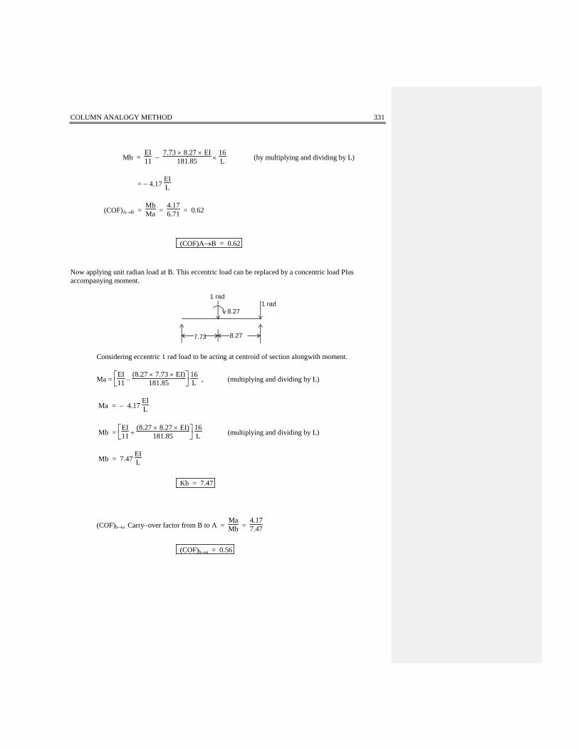
Mb = EI11 −
7.73 × 8.27 × EI181.85 ×
16L (by multiplying and dividing by L)
= − 4.17 EIL
(COF)A→B = MbMa =
4.176.71 = 0.62
(COF)A→B = 0.62 Now applying unit radian load at B. This eccentric load can be replaced by a concentric load Plus accompanying moment.
8.271 rad
1 rad
8.277.73 Considering eccentric 1 rad load to be acting at centroid of section alongwith moment.
Ma =
EI
11 − (8.27 × 7.73 × EI)
181.85 16L , (multiplying and dividing by L)
Ma = − 4.17 EIL
Mb =
EI
11 + (8.27 × 8.27 × EI)
181.85 16L (multiplying and dividing by L)
Mb = 7.47 EIL
Kb = 7.47
(COF)b→a Carry−over factor from B to A = MaMb =
4.177.47
(COF)b→a = 0.56

332 THEORY OF INDETERMINATE STRUCTURES
7.4. APPLICATION TO FRAMES WITH ONE AXIS OF SYMMETRY:− EXAMPLE NO. 9:- Analyze the quadrangular frame shown below by the method of column analogy. Check the solution by using a different B.D.S. SOLUTION:−
12KNB C
DA
6m 2I 2I 6m
5I
10m
Axis of Symmetry w.r.t. geometry
The term “axis of symmetry” implies that the shown frame is geometrically symmetrical (M.O.I. and support conditions etc., are symmetrical) w.r.t. one axis as shown in the diagram. The term does not include the loading symmetry (the loading can be and is unsymmetrical). Choosing the B.D.S. as a cantilever supported. at A.
12KNB C
DA
6m 6m
10m
72 kN-m
Ms-diagram
5I
2I 2I
AD
CB 5I
6m 2I6m 2I
2Force=108
EI36
- DiagramMsEI
12 kN-m
EI

COLUMN ANALOGY METHOD 333
According to our sign convention for column analogy, the loading arising out of negative MsEI giving tension
on outside will act upwards on the analogous column section. Sketch analogous column section and place load.
x x
B C
AD
y
Mxx5m 5m
Myy3.73m
2m
1/212
108EI
15
y=2.27m
(1) Properties of Analogous Column Section:−
A =
1
2 × 6 × 2 + 15 × 10 =
8EI
y =
1
5 × 10 × 1
10 + 2
1
2 × 6 × 3 1EI
8EI
= 2.27 m about line BC. (see diagram)
Ixx = 2
0.5 × 63
12 +
1
2 × 6 x (0.73)2 + 10 × (1/5)3
12 + (0.2 × 10) × (2.27)2
= 31.51
EI m4
Iyy = 0.2 × 10³
12 + 2
6 × 0.53
12 + (6 × 0.5) × (5)2
= 167EI m4
Mxx = 108 × 1.73 = 187EI clockwise.
Myy = 108 × 5 = 540EI clockwise.
Applying the formulae in a tabular form for all points. Imagine the direction of reactions at exterior frame points due to loads and moments. Ma = ( Ms− Mi)a
( Mi)a = PA ±
Mx yIx ±
My XIy

334 THEORY OF INDETERMINATE STRUCTURES
POINT Ms P/A Mx y
Ix My X
Iy Mi M =
Ms−Mi A − 72 − 13.5 − 22.14 − 16.17 − 51.81 − 20.19 B 0 − 13.5 + 13.47 − 16.17 − 16.20 + 16.20 C 0 − 13.5 + 13.47 + 16.17 + 16.14 − 16.14 D 0 − 13.5 − 22.14 + 16.17 − 19.47 + 19.47
Note: Imagine the direction of reaction due to P, Mx and My at all points A, B, C and P. Use appropriate signs. Repeat the analysis by choosing a different BDS yourself. EXAMPLE NO. 10:− Analyze the quadrangular frame shown by the method of column analogy.
A
B C
D
6m6m
5I
3KN/m
10m
2I 2I
Choosing B.D.S. as a cantilever supported at A.
B C
DA
150K n-m
3KN/m
30BDS under loads
COLUMN ANALOGY METHOD 335
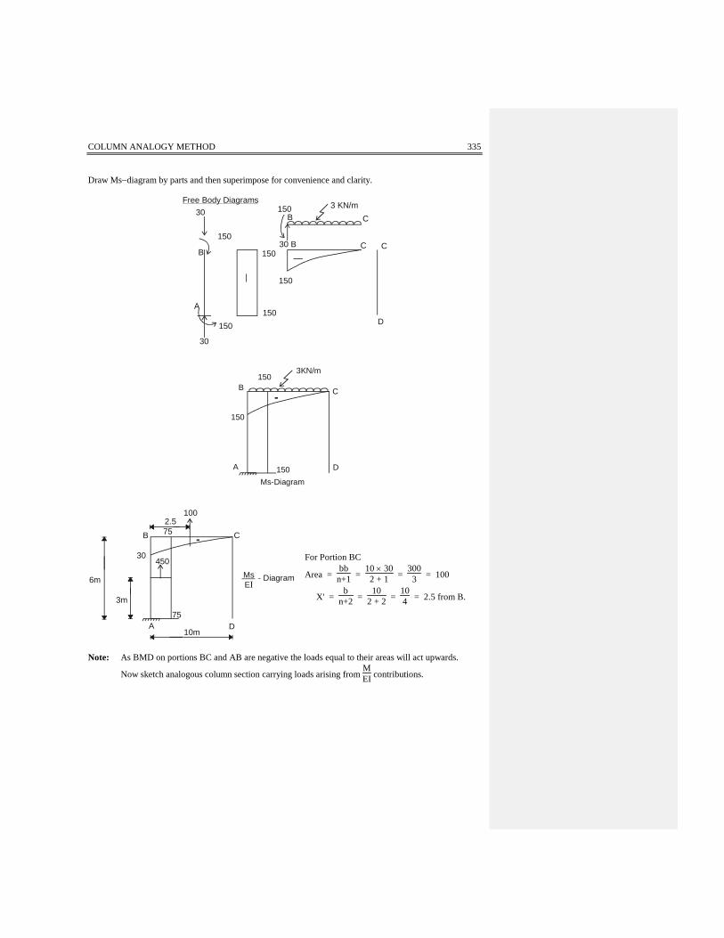
Draw Ms−diagram by parts and then superimpose for convenience and clarity.
30
150
B
A
150150
150
150
30 B C
C
C
D
B
Free Body Diagrams 3 KN/m
30
150
150
150B
3KN/m
C
D150A
Ms-Diagram
6m
3m
450
CB
2.575
75
10m
MsEI
- Diagram
30
100
A D
For Portion BC
Area = bb
n+1 = 10 × 302 + 1 =
3003 = 100
X' = b
n+2 = 10
2 + 2 = 104 = 2.5 from B.
Note: As BMD on portions BC and AB are negative the loads equal to their areas will act upwards.
Now sketch analogous column section carrying loads arising from MEI contributions.

336 THEORY OF INDETERMINATE STRUCTURES
2.275m450
B2.25m 100 y
C1/5
XX
3.725
6m 0.725m
3m
1/2 1/210m
D
My
Mx
yAnalogus colmun section
Properties of analogous column section:−
A = 2
1
2 × 6 + 15 × 10 =
8EI (as before)
y =
1
5 × 10 × 1
10 + 2
6 ×
12 × 3
8 = 2.275 about line BC (as before)
Ix = 2
1
2 × 63 +
1
2 × 6 × (0.725)2 +
10 ×
1
5
3
+
10 ×
15 × (2.275)2
= 31.51
EI m4 (as before)
Iy = 2
6 × 0.53
12 + (6 × 0.5) × 52 + 0.2 × 10³
12
= 166.79
EI m4 (as before)
Mx = 450 × 0.725 − 100 × 2.275 = 95.75 KN−m Clockwise My = 450 × 5 + 100 × 2.75 = 2525 KN−m clockwise. P = 100 + 450 = 550 KN
Now this eccentric load P and MX and My are placed on column centroid. Applying the formulae in a tabular form. Ma = ( Ms− Mi)a

COLUMN ANALOGY METHOD 337
and ( Mi)a = PA ±
Mx yIx ±
My xIy
POINT Ms P/A Mx . y
Ix My . x
Iy Mi M =
Ms−Mi A − 150 − 68.75 − 11.32 − 75.69 − 155.76 5.76 B − 150 −68.75 + 6.91 − 75.69 − 137.53 −12.47 C 0 −68.75 + 6.91 + 75.69 13.85 −13.85 D 0 −68.75 −11.32 + 75.69 −4.38 4.38
EXAMPLE NO. 4:− Determine stiffness factors corresponding to each end and carry-over factors in both directions of the following beam. SOLUTION:−
2m 1.5m 2m 1m 2m5I 2I 4I I 3I
A B
Sketch analogous column section.
1/5 ½ ¼ 1/EI 1/3EI
4.74m 3.76m
yo
o
Properties of Analogous Column Section :− A =
15 × 2 +
12 × 1.5 +
14 × 2 + 1 × 1 +
13 × 2
A = 3.32EI
Taking moment about B of various segments of column section.
X = 13 × 2 × 1 + 1 × 1 × 2.5 +
14 × 2 × 4 +
12 × 1.5 × 5.75 +
15 × 2 × 7.5
3.32
X = 12.4725
3.32
X = 3.76 m from B.

338 THEORY OF INDETERMINATE STRUCTURES
Iyoyo = 13 ×
23
12 +
1
3 × 2 × (2.76)2 + 1 × 13
12 + (1 × 1)(2.26)2
+
1
4 × (2)3
12 +
1
4 × 2 (0.24)2 +
1
2 × (1.5)3
12
+
1
2 × 1.5 (1.99)2 +
1
5 × (2)3
12 +
1
5 × 2 (3.74)2
= 19.53
EI
1. Determination of stiffness factor at A (ka) and carry-over factor from A to B. Apply unit load at
A and then shift it along with moment to centroidal axis of column as shown below:
1 rad
A B8.5m
1
4.74 BA
4.74 3.76
=
Ma =
PA ±
MCI
= 1 × EI
3.32 + 4.74 × 4.74 EI
19.53
= 1.45 EI , multiply and divide by L
Ma = 1.45 × 8.5 × EIL = 12.33
EIL
Ka = 12.33
Mb = EI
3.32 − 4.74 × 3.26 × EI
19.53
= − 0.61 EI = − 0.61 × 8.5 × EIL = − 5.19
EIL (multiply and divide by L)
Mb = − 5.19 EIL
(COF)a → b = MbMa =
5.1912.33 = 0.42
(COF)a → b = 0.42

COLUMN ANALOGY METHOD 339
2. Determination of stiffness factor at B (Kb) and carry-over from B to A. Apply a unit load at B and them shift it along with moment to centroidal axis of column as shown below:
Ma = PA ±
McI
1 rad
A B8.5m
1
3.76 BA
4.74 3.76
=
Ma = EI
3.32 − 3.76 × 4.74 × EI
19.53
= −0.61EI , multiply and divide by L.
= − 0.61 × 8.5 × EIL = −5.19
EIL
Mb = PA ±
McI
= EI
3.22 + 3.76 × 3.76 × EI
19.53
=1..03 EI = 1.03 × EIL × 8.5 , multiply and dividing by L.
Mb = 8.76 EIL
Kb = 8.76
(COF)b → a = MaMb =
5.198.76 = 0.6
(COF) b → a = 0.6

340 THEORY OF INDETERMINATE STRUCTURES
EXAMPLE NO.12:− Analyze the following gable frame by column analogy method. SOLUTION :−
3 kN/m
3 m
7 m
A E
B DC
14 m
I
3I 3I
I
Choosing a simple frame as BDS
A
B D
E
3kN/m
7.62
7
21 21B.D.S under loads
C
73.573.5
A E
B DC
7.62
Ms-diagram
A
B
C
D
EMs diagramEI
24.5 24.5
4.375
4.76 2.86x
2.86
COLUMN ANALOGY METHOD 341
Taking the B.D.S. as a simply supported beam.
MX = 21X – 1.5X2 , taking X horizontally. MX = Mc at X = 7m Mc = 21 × 7 – 1.5 X 72 = 73.5 KN−m
Sin θ = 3
7.62 = 0.394
Cos θ = 7
7.62 = 0.919
P1 = P2 = 23 × 24.5 × 7.62 = 124.46
P = P1 + P2 = 248.92
∫ MX dX = 7
∫o (21 X − 1.5X2) dX =
21
2 X2 − 1.53 X3
7 o= 343
∫ (MX)X dX = 7
∫o (21 X2 − 1.5X3)dX =
21
3 X3 − 1.54 X4
7 o
= 7 × 73 − 1.54 × 74 = 1500.625
X = ∫ (MX) X dX
∫ MX dX = 1500.625
343
X = 4.375 Horizontally from D or B. Shift it on the inclined surface.
Cos θ = 4.375
a
a = 4.375Cos θ =
4.3750.919
a = 4.76

342 THEORY OF INDETERMINATE STRUCTURES
Now draw analogous column section and place loads on top of it.
1
A
E
1
4.83 mMx
XX
2.17 m
3mB
C
1/3D
2.86
4.76
124.46124.46
PROPERTIES OF ANALOGOUS COLUMN SECTION
A = 2 (1 × 7) + 2
1
3 × 7.62 = 19.08 m2
Y = 2[(1 × 7) × 3.5] + 2
1
3 × 7.62 × 8.5
19.08 = 49 + 43 − 18
19.08
Y = 4.83 m from A or E
Ix = 2
1 × 73
12 + (1 × 7) (4.83 − 3.5)2
+ 2
1
3 × (7.62)3
12 × ( 0.394 )2 + 13 (7.62) ( 1.5 + 2.17)2 ,
the first term in second square bracket is bL3
12 Sin2θ
= 154.17 So Ix ≅ 154 m4
Now Iy = 2
7 × 13
12 + (7 × 1) × 72
+ 2
1
3 × (7.62)3
12 × (0.919 )2 +
1
3 × 7.62 × (3.5)2 ,

COLUMN ANALOGY METHOD 343
the first term in second square bracket is bL3
12 Cos2θ
=770.16 So Iy ≅ 770 m4 Total load on centroid of analogous column P = P1 + P2 = 124.46 + 124.46 = 248.92 KN Mx = 2 × [124.46 × 4.05 ] , 4.05 = 2.17 + 4.76 Sinθ = 2.17 + 4.76 × 0.394.
Mx = 1007 (clockwise).
My = 0 (because moments due to two loads cancel out)
Applying the general formulae in a tabular form for all points of frame. Ma = ( Ms− Mi)a
( Mi)a = PA ±
Mx yIx ±
My XIy
Point Ms (A)
P/A (1)
Mx .YIx
(2)
My .XIy
(3)
(B)=Mi (1)+(2) +(3)
M = Col (A)−(B)
A 0 + 13.05 − 31.58 0 − 18.53 + 18.53 B 0 + 13.05 + 14.19 0 + 27.24 − 27.24 C + 73.5 + 13.05 + 33.81 0 + 46.86 +26.64 D 0 + 13.05 + 14.19 0 + 27.24 − 27.24 E 0 + 13.05 − 31.58 0 − 18.53 + 18.53
EXAMPLE NO. 13:- Analyze the frame shown in fig below by Column Analogy Method.
B C
A D
2kN/m
10kN
4m
3m
2I
3I
2I
Choosing the B.D.S. as a cantilever supported at A.

344 THEORY OF INDETERMINATE STRUCTURES
MA = 10 x 1.5 + 2 x 4 x 42
MA = 31 KN−m
318
10
2kN/m
10 kN
B.D.S
B C
A D
Draw Free Body Diagrams and sketch composite BMD:−
10
10
831
2kN/m
B
15
A
31
15
15
15
10
10
CB1.5 1.5
C
D
no B.M.D4m
31
15
15
10
Ms-diagram15.5
7.5
5
10
MsEI diagram
,
COLUMN ANALOGY METHOD 345
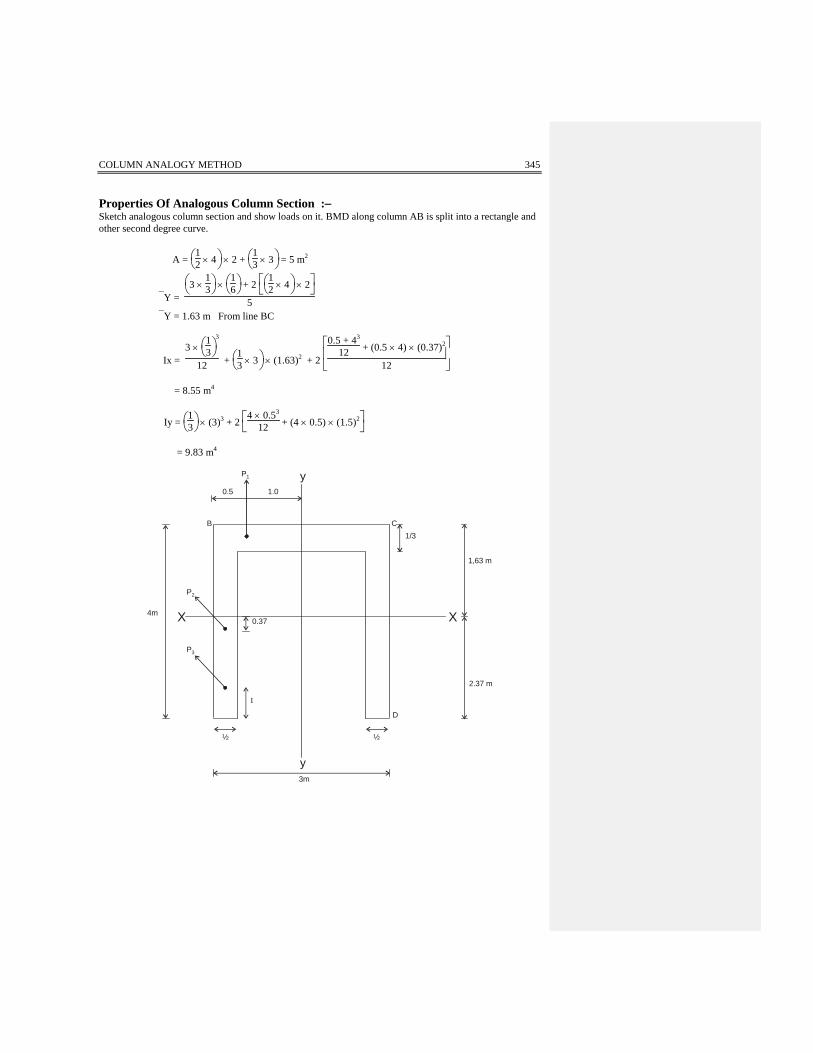
Properties Of Analogous Column Section :− Sketch analogous column section and show loads on it. BMD along column AB is split into a rectangle and other second degree curve.
A =
1
2 × 4 × 2 +
1
3 × 3 = 5 m2
Y =
3 ×
13 ×
1
6 + 2
1
2 × 4 × 2
5
Y = 1.63 m From line BC
Ix = 3 ×
1
3
3
12 +
1
3 × 3 × (1.63)2 + 2
0.5 + 43
12 + (0.5 × 4) × (0.37)2
12
= 8.55 m4
Iy =
1
3 × (3)3 + 2
4 × 0.53
12 + (4 × 0.5) × (1.5)2
= 9.83 m4
2.37 m
1,63 m
1/3
D
½½
I
y3m
yP1
1.00.5
B C
P2
P3
0.37X4m X
346 THEORY OF INDETERMINATE STRUCTURES
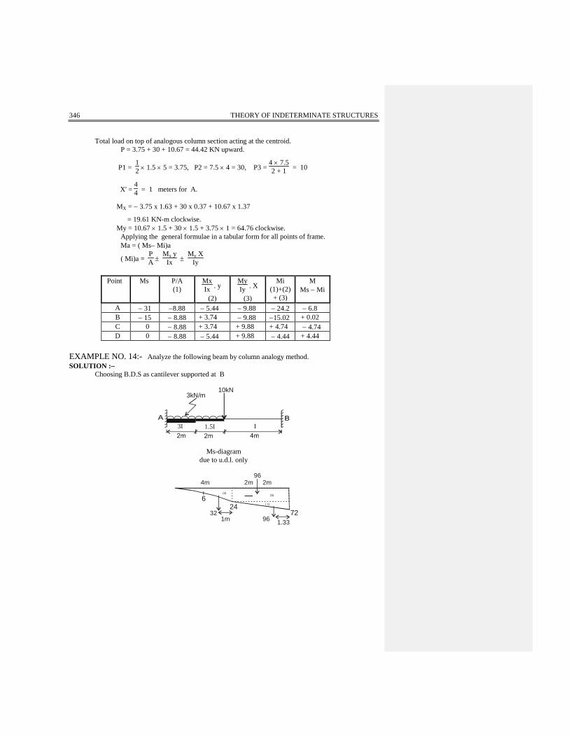
Total load on top of analogous column section acting at the centroid. P = 3.75 + 30 + 10.67 = 44.42 KN upward.
P1 = 12 × 1.5 × 5 = 3.75, P2 = 7.5 × 4 = 30, P3 =
4 × 7.52 + 1 = 10
X' = 44 = 1 meters for A.
MX = − 3.75 x 1.63 + 30 x 0.37 + 10.67 x 1.37
= 19.61 KN-m clockwise. My = 10.67 × 1.5 + 30 × 1.5 + 3.75 × 1 = 64.76 clockwise. Applying the general formulae in a tabular form for all points of frame. Ma = ( Ms− Mi)a
( Mi)a = PA ±
Mx yIx ±
My XIy
Point Ms P/A
(1) MxIx . y
(2)
MyIy . X
(3)
Mi (1)+(2) + (3)
M Ms − Mi
A − 31 −8.88 − 5.44 − 9.88 − 24.2 − 6.8 B − 15 − 8.88 + 3.74 − 9.88 −15.02 + 0.02 C 0 − 8.88 + 3.74 + 9.88 + 4.74 − 4.74 D 0 − 8.88 − 5.44 + 9.88 − 4.44 + 4.44
EXAMPLE NO. 14:- Analyze the following beam by column analogy method. SOLUTION :−
Choosing B.D.S as cantilever supported at B
3kN/m10kN
I1.5I3I
Ms-diagram
due to u.d.l. only
7224
6( c)
(b)(a)
962m2m4m
321m 96 1.33
COLUMN ANALOGY METHOD 347
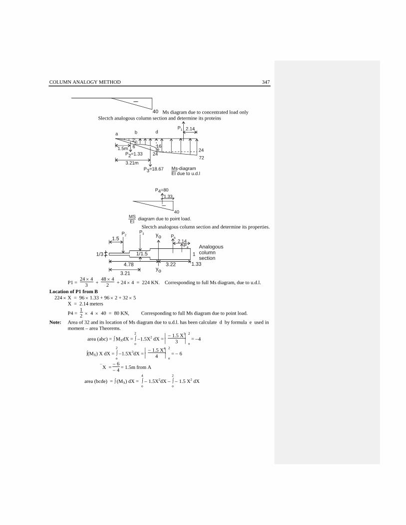
40 Ms diagram due to concentrated load only Slectch analogous column section and determine its proteins
a b d
ce 24
2472
161.5m
26
P2=1.33
3.21mP3=18.67
2.14
Ms-diagramEI due to u.d.l
P1
40
P4=801.33
MSEI diagram due to point load.
Slectch analogous column section and determine its properties.
1/1.5
o
yo3.224.78
1/3 1Analogouscolumnsection
2.14P6
P4
1.33
P3P21.5
3.21
P1 = 24 × 4
3 + 48 × 4
2 + 24 × 4 = 224 KN. Corresponding to full Ms diagram, due to u.d.l.
Location of P1 from B 224 × X = 96 × 1.33 + 96 × 2 + 32 × 5
X = 2.14 meters
P4 = 12 × 4 × 40 = 80 KN, Corresponding to full Ms diagram due to point load.
Note: Area of 32 and its location of Ms diagram due to u.d.l. has been calculate d by formula e used in moment – area Theorems.
area (abc) = ∫ MXdX = 2
∫o −1.5X2 dX =
− 1.5 X3
3
2 o = −4
∫(MX) X dX = 2
∫o −1.5X3dX =
− 1.5 X4
4
2 o = − 6
X = − 6− 4 = 1.5m from A
area (bcde) = ∫ (MX) dX = 4
∫o − 1.5X2dX −
2
∫o − 1.5 X2 dX

348 THEORY OF INDETERMINATE STRUCTURES
=
− 1.5
X3
3
4 o −
− 1.5
X3
3
2 o = − 28
∫ (MX)X dX = 4
∫o− 1.5 X3dX −
2
∫o − 1.5 X3dX = − 90
X = −90−28
= 3.21 meters from A (centroid of area bcde)
P3 = 1
1.5 (area bcde) = 1
1.5 (28) = 18.67 KN , P2 = 13 area abc =
13 × 4 = 1.33
P4 = 80 KN Total concentric load on analogous column section. P = − P1 + P2 + P3 − P4
= − 224 + 1.33 + 18.67 − 80 = − 284 KN (upward)
Total applied moment = M = − 224 × 1.68− 80 × 1.89 − 18.67 × 1.57 − 1.33 × 33 × 3.28
= − 426.79 KN-m (It means counter clockwise)
This total load P and M will now act at centroid of analogous column section. Properties of Analogous Column Section.
A = 13 × 2 +
11.5 × 2 + 1 × 4 = 6
X = (1 × 4) × 2 +
2 ×
11.5 × 5 +
1
3 × 2 × 7
6
= 3.22 from B.
Iyoyo = 1 × 43
12 + (1 × 4)(1.22)2 +
1
1.5 × 23
12 +
1
1.5 × 2 (1.78)2
COLUMN ANALOGY METHOD 349
+
1
3 × 23
12 +
1
3 × 2 (3.78)2
12 = 25.70 m4
(Mi)a = PA ±
McI
= − 284
6 + 426.79 × 4.78
25.7
= + 32.05 KN-m (Ms)a = 0 Ma = (Ms − Mi)a = 0 − 32.05 Ma = − 32.05 KN−m
(Mi)b = PA −
McI
= − 284
6 − 426.79 × 3.22
25.7
= − 100.81 (Ms)b = − 72 − 40 = − 112 Mb = (Ms − Mi)b = − 112 + 100.81 Mb = − 11.19 KN−m The beam has been analyzed. It is now statically determinate.


![Fast Multi-Precision Multiplication for Public-Key ...method (also referred as Comba [4] or column-wise multiplication method). There, each partial product is processed in a column-wise](https://static.fdocuments.in/doc/165x107/5f1cd208c17edf209e5ec6d3/fast-multi-precision-multiplication-for-public-key-method-also-referred-as.jpg)


