INTRODUCTION TO CNC ESSENTIALS - ‘The Balsa Challenge’ 3 ...
15
INTRODUCTION TO CNC ESSENTIALS - ‘The Balsa Challenge’ CNC controlled spindles are not difficult to use, but they do require some preparation in advance of using the machine, and they are potentially hazardous. Before we allow anyone to use the machines for themselves, you need to know: 1. What you can and cannot use the machines for, what the main hazards are, and how you can reduce the risk of incidents occurring. 2. How to use the Fab Lab Digital Machines Template file. 3. What you need in your CAD drawing. 4. How to program your files in Rhino CAM ready for cutting. This knowledge is set out as 4 steps in an online guide below. If you need help please come to the lab between 12 and 1 Monday to Thursday. STEP 1 WHAT YOU CAN AND CANNOT DO. What is a CNC spindle and how do we control it? A Spindle is a very fast spinning motor that holds an END MILL. The end mill spins at a specific SPEED and the machine that the spindle is attached to FEEDS it through the material to cut away the material in its path. This is what is known as the TOOL PATH. The machine that the spindle is attached to is either a MILL or a ROUTER. The machine is controlled by a computer, hence COMPUTER NUMERICAL CONTROL- CNC. The computer code is generated out of your Rhino CAD file by using a CAM (Computer Aided Manufacturing) plugin call RhinoCAM. The basics of what a CNC spindle can do and what can it not do. What it can do. At a very basic level the End Mill can cut 2 dimensional shapes by using two axis - the X and the Y - it can also create what is called a POCKET by cutting away a set region, down to a specified depth. However, it can do more. Using it’s 3rd axis - the Z axis- the machine can cut simultaneously with the X, Y and Z. This enables complex surfaces to be machined. What it cannot do.
Transcript of INTRODUCTION TO CNC ESSENTIALS - ‘The Balsa Challenge’ 3 ...
INTRODUCTION TO CNC ESSENTIALS - ‘The Balsa Challenge’
CNC controlled spindles are not difficult to use, but they do require some preparation in advance of using the machine, and they are potentially hazardous. Before we allow anyone to use the machines for themselves, you need to know: 1. What you can and cannot use the machines for, what the main hazards are, and how you can reduce the risk of incidents occurring. 2. How to use the Fab Lab Digital Machines Template file. 3. What you need in your CAD drawing. 4. How to program your files in Rhino CAM ready for cutting. This knowledge is set out as 4 steps in an online guide below. If you need help please come to the lab between 12 and 1 Monday to Thursday. STEP 1 WHAT YOU CAN AND CANNOT DO.
What is a CNC spindle and how do we control it?
A Spindle is a very fast spinning motor that holds an END MILL. The end mill spins at a specific SPEED and the machine that the spindle is attached to FEEDS it through the material to cut away the material in its path. This is what is known as the TOOL PATH. The machine that the spindle is attached to is either a MILL or a ROUTER. The machine is controlled by a computer, hence COMPUTER NUMERICAL CONTROL- CNC. The computer code is generated out of your Rhino CAD file by using a CAM (Computer Aided Manufacturing) plugin call RhinoCAM.
The basics of what a CNC spindle can do and what can it not do.
What it can do. At a very basic level the End Mill can cut 2 dimensional shapes by using two axis - the X and the Y - it can also create what is called a POCKET by cutting away a set region, down to a specified depth. However, it can do more. Using it’s 3rd axis - the Z axis- the machine can cut simultaneously with the X, Y and Z. This enables complex surfaces to be machined.
What it cannot do.

Fig 1.1 The end mill cannot cut pockets or internal parts smaller than the tools diameter. They cannot cut ‘undercuts’ (see the diagram below), this requires a 5 Axis CNC machine (our machines are 3 axis). They cannot cut deeper than the specific end mill will allow. Most* of our end mills are designed to cut through 50mm (our thickest stock material). *There are exceptions, Peter and Bernard will not cut deeper than 40 mm using a 6mm end mill and the 3mm end mill cuts to 10mm in depth.
What CNC Spindles do we have and what tools do they use?
We have 7 CNC spindles:
The MILLS (we have 5)
Peter, Bernard and Daniel are Mills; in fact they are so small we call them mini mills. These are machines that you will complete the CNC essentials on.
They can cut: Blue and Black polystyrene, Cream polyurethane.
Rem and Bjarke are larger than Peter and Bernard. They also have an automatic tool change so they can swap their end mill automatically based on your file.
They can cut: the same as Peter, Bernard and Daniel but also higher density orange foam.
The ROUTERS (we have 2)
Renzo and Norman are routers, unlike the mills their bed stays static and the gantry moves. These are designed for large sheet material but can also cut foam. Norman has an automatic tool change, Renzo does not.
They can cut: Ply, MDF, Acrylic and all foams.
The TOOLS
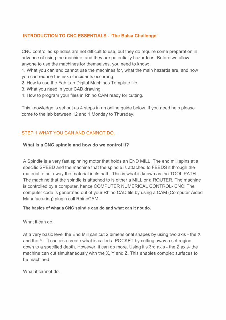
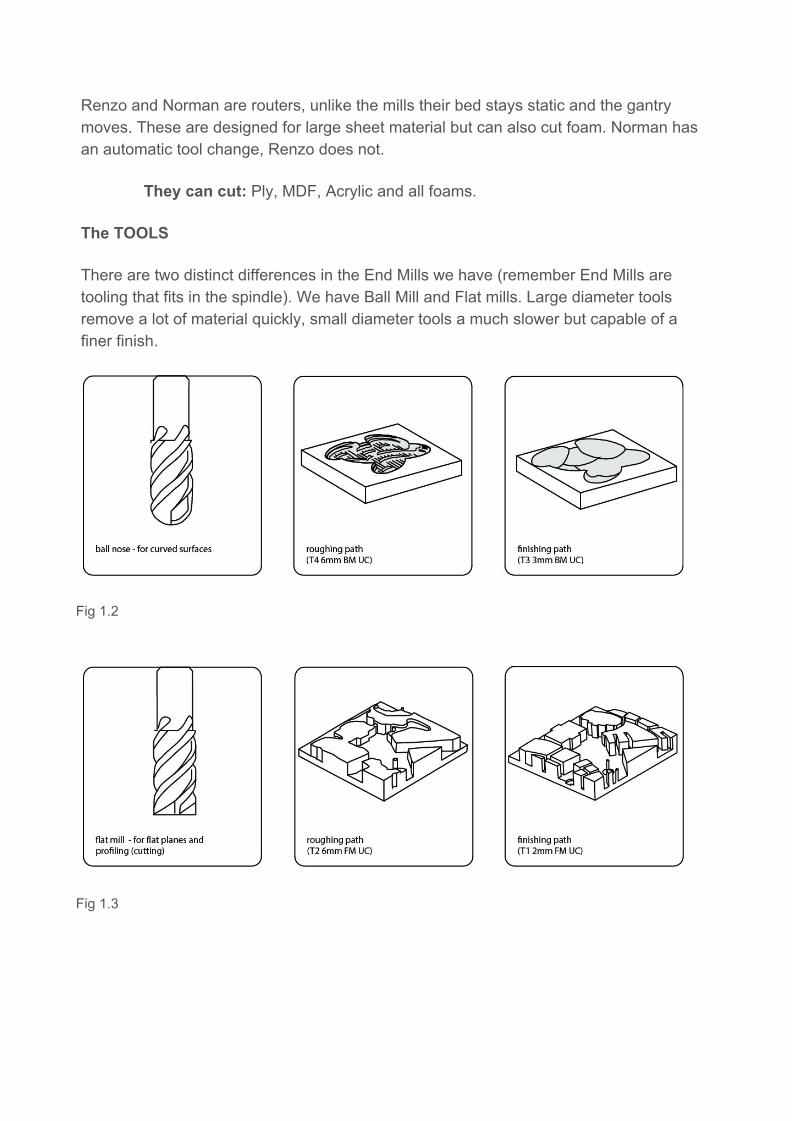
There are two distinct differences in the End Mills we have (remember End Mills are tooling that fits in the spindle). We have Ball Mill and Flat mills. Large diameter tools remove a lot of material quickly, small diameter tools a much slower but capable of a finer finish.
Fig 1.2
Fig 1.3

Fig 1.4
WHAT ARE THE HAZARDS?
The hazards involved with using high speed spindles and moving CNC machines can be great. The smaller Mills are less hazardous as they are enclosed. The larger routers are extremely powerful and have more hazards with greater consequences.
COLLISION - [HAZARD] As the mini mills are enclosed the risk of collision with yourself and the machine is not possible. This is not the case with Norman and Renzo. [CONTROL]To control this hazard we insist that you observe the machine from outside of the machine room. You must in no circumstances interfere with the machine or the material while the machine is in operation.
FIRE - [HAZARD] As the spindles rotate at an extremely high speed friction is created. If the End Mill is blunt then this friction can be much greater causing the material to ignite. Fire is a very real possibility on the routers. [CONTROL]Therefore when using Norman or Renzo, and observing from outside of the machine room, you must never lose sight of the End Mill.
HARMFUL INHALATION - [HAZARD] The end mills remove material as fine chips this can be a fine inhalable particulate. The mini mills are enclosed and the Routers have high power extraction systems however the particulate can still be made airborne when the material is moved. [CONTROL] Therefore when you have finished cutting be sure to vacuum as much as possible before moving the stock material.
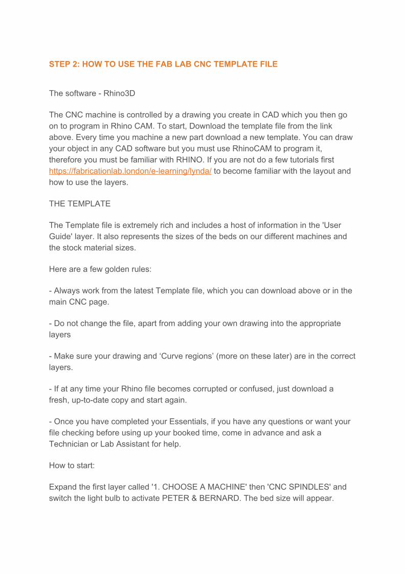
STEP 2: HOW TO USE THE FAB LAB CNC TEMPLATE FILE
The software - Rhino3D
The CNC machine is controlled by a drawing you create in CAD which you then go on to program in Rhino CAM. To start, Download the template file from the link above. Every time you machine a new part download a new template. You can draw your object in any CAD software but you must use RhinoCAM to program it, therefore you must be familiar with RHINO. If you are not do a few tutorials first https://fabricationlab.london/e-learning/lynda/ to become familiar with the layout and how to use the layers.
THE TEMPLATE
The Template file is extremely rich and includes a host of information in the 'User Guide' layer. It also represents the sizes of the beds on our different machines and the stock material sizes.
Here are a few golden rules:
- Always work from the latest Template file, which you can download above or in the main CNC page.
- Do not change the file, apart from adding your own drawing into the appropriate layers
- Make sure your drawing and ‘Curve regions’ (more on these later) are in the correct layers.
- If at any time your Rhino file becomes corrupted or confused, just download a fresh, up-to-date copy and start again.
- Once you have completed your Essentials, if you have any questions or want your file checking before using up your booked time, come in advance and ask a Technician or Lab Assistant for help.
How to start:
Expand the first layer called '1. CHOOSE A MACHINE' then 'CNC SPINDLES' and switch the light bulb to activate PETER & BERNARD. The bed size will appear.

Next, expand '2. CHOOSE YOUR STOCK' then 'CNC SPINDLES' expand BALSA and activate the layer called 'Balsa Challenge' using the light bulb. This is the size of your stock material.
Now expand the layer called '3. DRAW YOUR PARTS' - 'CNC SPINDLES'. Below is a screen grab of what you should have.
STEP 3 - WHAT YOU WILL NEED IN YOUR CAD DRAWING To complete the CNC Essentials, you must produce a part to be cut. This is ‘The Balsa Challenge’.
● This must be a two-part joint cut from one piece of balsa wood. ● The stock material (the balsa wood) is 65mm x 70mm ● Each part of the joint can be no bigger than 50mm x 20mm.
In the layers that you place your work you have seen there are 2 axis operations and 3 axis operations.
2 axis operations require curves these are known as Curve regions. These operations include Pocketing and Profiling (cutting).

3 axis operations require surfaces. With a region (a curve) drawn around the surface. These Operations include Roughing and Finishing.
In the template file under USER GUIDES you will find more information regarding each operation.
What you will need to Prepare for the next step of the CNC Essentials
● A 3D model* of each part of your joint set out in one file. The example below in Fig 3.1 is very basic we expect more creativity. For ideas on designing your joint either come down to the lab to see past examples or ‘google’ ‘cnc wood joints’ for ideas.
Things to remember when designing your joint.
1. The smallest tool diameter is 2mm 2. The tools cannot cut sharp internal corners (refer back to fig 1.1). 3. You must have curves drawn to specify your operations, for example pocketing,
and Profiling (Cutting).
*Although 2 axis machining only requires curves we do insist you create a 3-dimensional model of your joint
Fig 3.1
Now you have all your geometry in the right layers you're ready to use RhinoCam
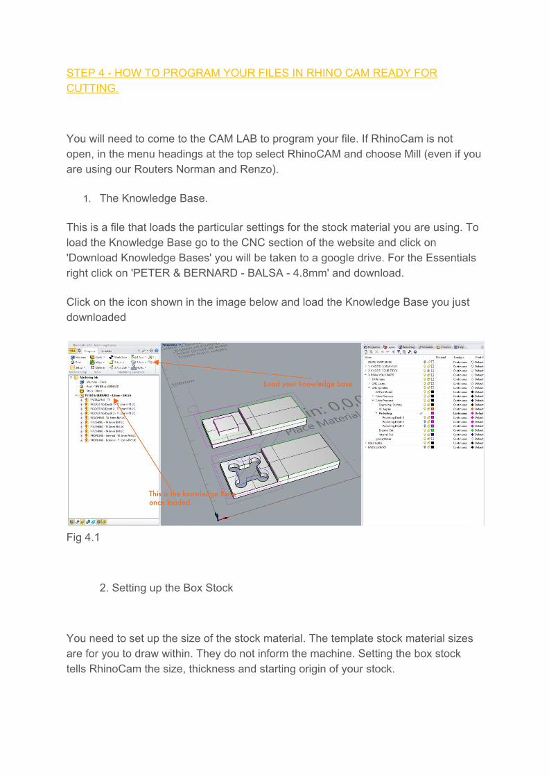
STEP 4 - HOW TO PROGRAM YOUR FILES IN RHINO CAM READY FOR CUTTING.
You will need to come to the CAM LAB to program your file. If RhinoCam is not open, in the menu headings at the top select RhinoCAM and choose Mill (even if you are using our Routers Norman and Renzo).
1. The Knowledge Base.
This is a file that loads the particular settings for the stock material you are using. To load the Knowledge Base go to the CNC section of the website and click on 'Download Knowledge Bases' you will be taken to a google drive. For the Essentials right click on 'PETER & BERNARD - BALSA - 4.8mm' and download.
Click on the icon shown in the image below and load the Knowledge Base you just downloaded
Fig 4.1
2. Setting up the Box Stock
You need to set up the size of the stock material. The template stock material sizes are for you to draw within. They do not inform the machine. Setting the box stock tells RhinoCam the size, thickness and starting origin of your stock.

Fig 4.2
3. Programing your operations
All machining operations require a region to machine. This is your curve. Double click on the operation in the Knowledge Base. Now from the pop up window 'select Curve / Edge region', Select the curves from your Rhino Layers* by right clicking on the layer of the operation you need and choose ‘Select Objects’ then press Enter. Once selected click ‘Generate’. *You must have first placed all your geometry in the correct layers as set out in Stage 1

Fig 4.3
For Pocketing, only - You will need to click on the ‘Cut Levels’ tab and specify a depth to which the machine will cut (see screen grab below).

Fig 4.4
4. Check tool paths
Now you have programmed each operation. Check each operation’s toolpaths by clicking on each operation and looking at the tool paths in the Top, Front and Perspective viewport to check that they are machining what you have programmed.
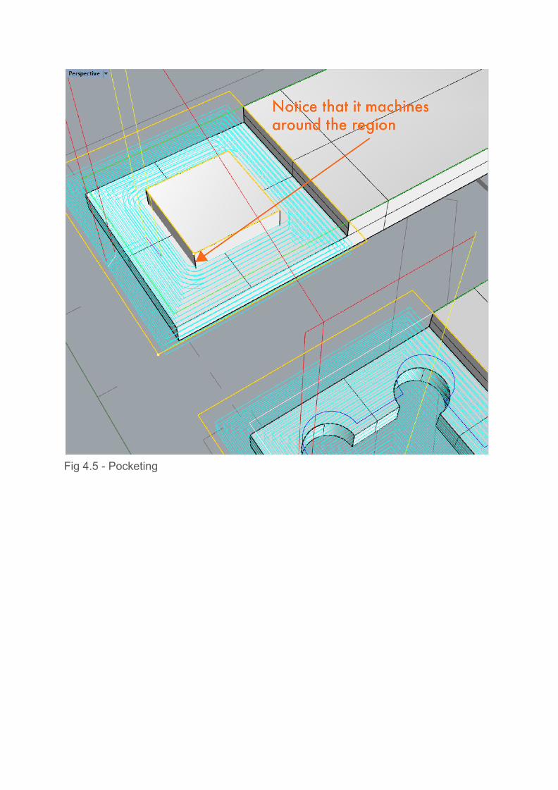
Fig 4.5 - Pocketing
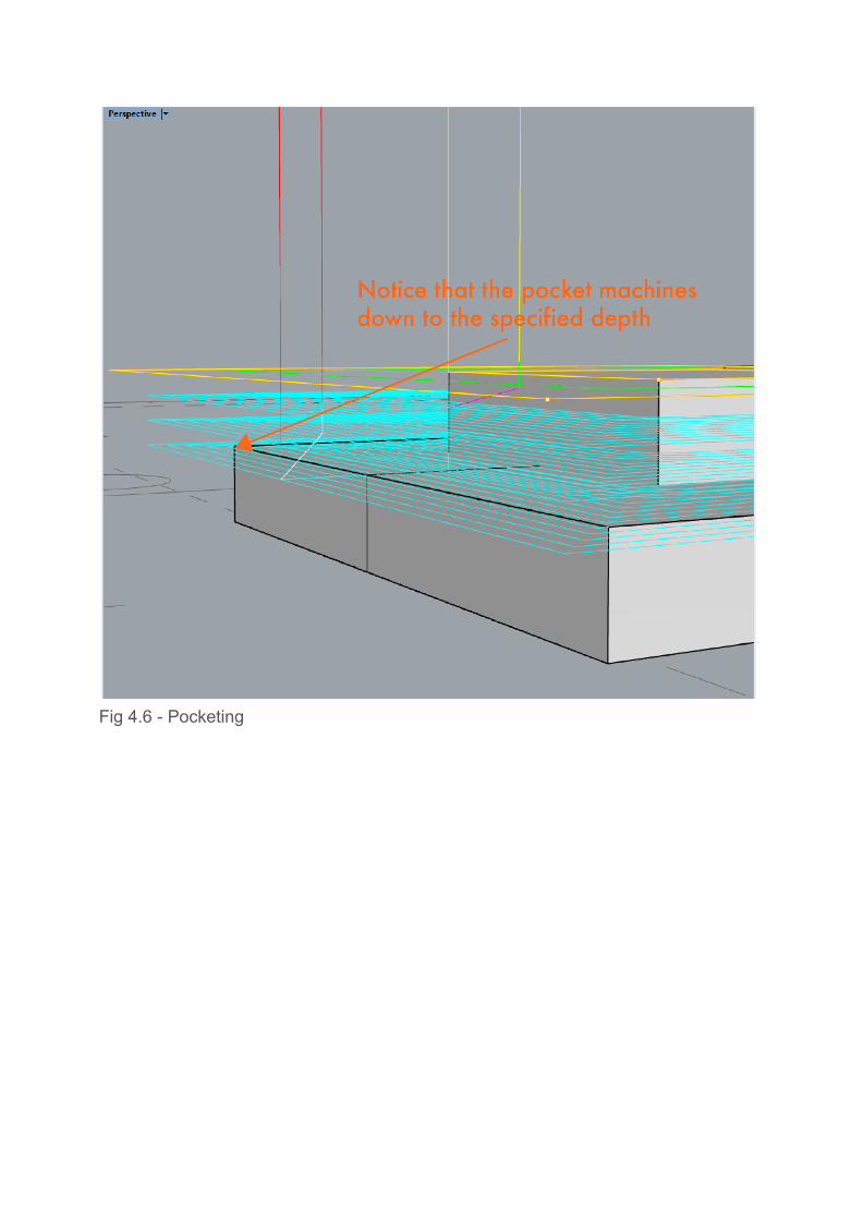
Fig 4.6 - Pocketing

Fig 4.7 - Profiling / Cutting
5. Time to ‘Post’. The mini mills used for the essentials have a slight quirk that none of the other machines have. You must select all your curves and type ‘Convert’ and convert all the curves to ‘lines’. This is because the Mini mills cannot interpret Curves and Arc. Once this is done right click on your knowledge base and ‘Regenerate’ all your operations. To process the CAM file into the G-code that the machine will read you need to 'Post' the file. For Machines that have no automatic tool change (that is Peter, Bernard, Daniel and Renzo) you need to Post each process separately. Right click on the Knowledge base operation and click ‘Post’. This will create a file called and NC post – save this onto a USB stick.
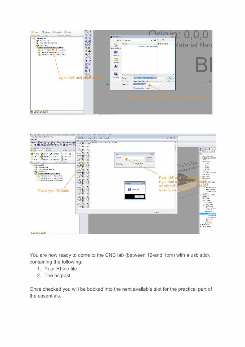
You are now ready to come to the CNC lab (between 12-and 1pm) with a usb stick containing the following:
1. Your Rhino file 2. The nc post
Once checked you will be booked into the next available slot for the practical part of the essentials.