Introduction to AutoCAD 2010 - Routledge · Introduction to AutoCAD 2010 Alf Yarwood Chapter 15...
9
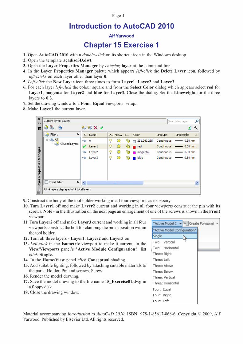
Introduction to AutoCAD 2010 Alf Yarwood Chapter 15 Exercise 1 1. Open AutoCAD 2010 with a double-click on its shortcut icon in the Windows desktop. 2. Open the template acadiso3D.dwt. 3. Open the Layer Properties Manager by entering layer at the command line. 4. In the Layer Properties Manager palette which appears left-click the Delete Layer icon, followed by left-clicks on each layer other than layer 0. 5. Left-click the New Layer icon three times to form Layer1, Layer2 and Layer3, . 6. For each layer left-click the colour square and from the Select Color dialog which appears select red for Layer1, magenta for Layer2 and blue for Layer3. Close the dialog. Set the Lineweight for the three layers to 0.3. 7. Set the drawing window to a Four: Equal viewports setup. 8. Make Layer1 the current layer. 9. Construct the body of the tool holder working in all four viewports as necessary. 10. Turn Layer1 off and make Layer2 current and working in all four viewports construct the pin with its screws. Note - in the Illustration on the next page an enlargement of one of the screws is shown in the Front viewport. 11. Turn Layer2 off and make Layer3 current and working in all four viewports construct the bolt for clamping the pin in position within the tool holder. 12. Turn all three layers - Layer1, Layer2 and Layer3 on. 13. Left-click in the Isometric viewport to make it current. In the View/Viewports panel’s *Active Module Configuration* list click Single. 14. In the Home/View panel click Conceptual shading. 15. Add suitable lighting, followed by attaching suitable materials to the parts: Holder, Pin and screws, Screw. 16. Render the model drawing. 17. Save the model drawing to the file name 15_Exercise01.dwg in a floppy disk. 18. Close the drawing window. Material accompanying Introduction to AutoCAD 2010, ISBN 978-1-85617-868-6. Copyright © 2009, Alf Yarwood. Published by Elsevier Ltd. All rights reserved. Page 1
Transcript of Introduction to AutoCAD 2010 - Routledge · Introduction to AutoCAD 2010 Alf Yarwood Chapter 15...
Introduction to AutoCAD 2010Alf Yarwood
Chapter 15 Exercise 11. Open AutoCAD 2010 with a double-click on its shortcut icon in the Windows desktop.2. Open the template acadiso3D.dwt.3. Open the Layer Properties Manager by entering layer at the command line.4. In the Layer Properties Manager palette which appears left-click the Delete Layer icon, followed by
left-clicks on each layer other than layer 0.5. Left-click the New Layer icon three times to form Layer1, Layer2 and Layer3, .6. For each layer left-click the colour square and from the Select Color dialog which appears select red for
Layer1, magenta for Layer2 and blue for Layer3. Close the dialog. Set the Lineweight for the threelayers to 0.3.
7. Set the drawing window to a Four: Equal viewports setup.8. Make Layer1 the current layer.
9. Construct the body of the tool holder working in all four viewports as necessary.10. Turn Layer1 off and make Layer2 current and working in all four viewports construct the pin with its
screws. Note - in the Illustration on the next page an enlargement of one of the screws is shown in the Frontviewport.
11. Turn Layer2 off and make Layer3 current and working in all fourviewports construct the bolt for clamping the pin in position withinthe tool holder.
12. Turn all three layers - Layer1, Layer2 and Layer3 on.13. Left-click in the Isometric viewport to make it current. In the
View/Viewports panel’s *Active Module Configuration* listclick Single.
14. In the Home/View panel click Conceptual shading.15. Add suitable lighting, followed by attaching suitable materials to
the parts: Holder, Pin and screws, Screw.16. Render the model drawing.17. Save the model drawing to the file name 15_Exercise01.dwg in
a floppy disk.18. Close the drawing window.
Material accompanying Introduction to AutoCAD 2010, ISBN 978-1-85617-868-6. Copyright © 2009, AlfYarwood. Published by Elsevier Ltd. All rights reserved.
Page 1

Material accompanying Introduction to AutoCAD 2010, ISBN 978-1-85617-868-6. Copyright © 2009, AlfYarwood. Published by Elsevier Ltd. All rights reserved.
Page 2

Material accompanying Introduction to AutoCAD 2010, ISBN 978-1-85617-868-6. Copyright © 2009, AlfYarwood. Published by Elsevier Ltd. All rights reserved.
Page 3

Chapter 15 Exercise 21. Open acadiso3d.dwt - left-click New... in the Quick Access toolbar.2. Construct the two sloping partitions first.
(a) In a Front view, construct two closed polyline outlines from which solids of revolution can be produced.(b) Call the Revolve tool from the Home/3D Modeling panel and form the required solids of revolution.
3. Set the window in the ViewCube/Top view.4. Construct the outlines for partitions and the surrounding 2 units thick walls and extrude the outlines to a height
of 15. Using the two tools Union and Subtract to form the partitions. Use the Fillet tool to fillet the right-hand corners of the partitions.
5. Construct the base from two polylines. Extrude the outer to a height of 15 and the inner to a height of 13.Place in the ViewCube/Front view and move the two into correct positions relative to each other. Subtractthe inner from the outer.
6. Still in the Front view make sure the partitions are at a correct height relative to the base and with Unionform a union of the base and partitions.
7. Place in the ViewCube/Isometric view and select 3D Hidden from the Home/View panel.
8. Place in the ViewCube/Top view and addsuitable lighting and a suitable material.
9. Place in the ViewCube/Isometric view andrender.
10. Save to a floppy disk with the file name15_Exercise02.dwg.
11. Close the drawing window.
Material accompanying Introduction to AutoCAD 2010, ISBN 978-1-85617-868-6. Copyright © 2009, AlfYarwood. Published by Elsevier Ltd. All rights reserved.
Page 4

Chapter 15 Exercise 31. Open acadiso3d.dwt - left-click New... in the Quick Access toolbar.2. Construct an extrusion for the plate, cylinders for the central part and the holes and a torus for the flange at
the outer edge of the large cylinder.
Material accompanying Introduction to AutoCAD 2010, ISBN 978-1-85617-868-6. Copyright © 2009, AlfYarwood. Published by Elsevier Ltd. All rights reserved.
Page 5

3 Place the drawing window in the ViewCube/Frontview and move the various solids to their correctpositions relative to each other and Zoom to 1.
4. While in the ViewCube/Front view, constructcylinders and a torus for the spindle bearing part ofthe component and an extrusion for the support piecebetween the upper and lower parts.
5. Go back to the ViewCube/Top view, and move theseparts to their correct positions relative to the otherparts and copy the torus to the other end of the spindlebearing.
6. Place the drawing area in the ViewCube/Isometricview, Zoom to 1 and using the Union and Subtracttools form the 3D model.
Material accompanying Introduction to AutoCAD 2010, ISBN 978-1-85617-868-6. Copyright © 2009, AlfYarwood. Published by Elsevier Ltd. All rights reserved.
Page 6

7. Place the drawing in the ViewCube/Top view, Zoom to 0.5and add suitable lighting. In this example one Point light is 800high above the model and two Distant lights one placed in frontand 900 high and the other to the left front and 600 high.
8. Attach a material to the model and render.9. Save the drawing to the file name 15_Exercise03.dwg in a
floppy disk.10. Close the drawing window.
Additional exercises
1. A drawing on the right gives details of the polyline fromwhich the rendered 3D solid model shown to its rightwas obtained. Construct the polyline and from the polylineconstruct the 3D solid model. Add suitable lighting anda material and render.
2. Construct and render a 3D solid model drawing of the support, working to the details given in the two-vieworthographic projection.
Material accompanying Introduction to AutoCAD 2010, ISBN 978-1-85617-868-6. Copyright © 2009, AlfYarwood. Published by Elsevier Ltd. All rights reserved.
Page 7

3. Construct and render the 3D solid model drawing of a support, working to the details given in the three-viewthird angle orthographic projection.
4. A rendering of a rotating arm from a machine is shown to the rightand details of the arm in a two-view orthographic projection isgiven below. Construct a 3D solid model drawing of the arm tothe given details, add lighting and a material and render the model.
Material accompanying Introduction to AutoCAD 2010, ISBN 978-1-85617-868-6. Copyright © 2009, AlfYarwood. Published by Elsevier Ltd. All rights reserved.
Page 8

Multiple choice questions1. Can Ambient lighting be set at a figure before rendering a 3D model:
(a) Yes(b) No(c) Requires a setting in a dialog(d) Set to a figure of 0.3
2. When setting lighting before rendering a 3D model Distant light can be described as:(a) A light the value of which diminishes in intensity the further the light position is set from the 3D model(b) Its light value is of the same intensity no matter how far the light position is set from the 3D model(c) Its intensity increases when set in front and above the 3D model compared with its being set to the sideand above the model(d) A light which sheds rays in all directions from its set position
3. Which in your opinion gives the best rendering results:(a) Medium(b) High(c) Presentation(d) They are all as good as each other
4. Can a 3D model which has been Conceptual shaded when using the 3D Orbit tool be rendered afterattaching materials:
(a) Yes(b) No(c) After materials have been added to a 3D model it cannot be Conceptual shaded(d) The 3D Orbit tool cannot be used after rendering has taken place
5. When printing or plotting a 3D model, which of the following statements is correct:(a) A rendered 3D model in a single viewport can be plotted in full colour(b) A Conceptual shaded 3D model in a single viewport can be plotted in full colour(c) A four-view viewport screen of a rendered 3D model in Model Space can be plotted in full colour(d) A four-view viewport screen of a Conceptual shaded 3D model in Model Space can be plotted in fullcolour
Material accompanying Introduction to AutoCAD 2010, ISBN 978-1-85617-868-6. Copyright © 2009, AlfYarwood. Published by Elsevier Ltd. All rights reserved.
Page 9