Introduction to ANSYS Mechanical Part 2 -...
12
© 2011 ANSYS, Inc. February 13, 2012 1 Release 14.0 14. 0 Release Introduction to ANSYS Mechanical Part 2 Workshop 7 Constraint Equations
Transcript of Introduction to ANSYS Mechanical Part 2 -...
© 2011 ANSYS, Inc. February 13, 20121 Release 14.0
14. 0 Release
Introduction to ANSYSMechanical Part 2
Workshop 7Constraint Equations

© 2011 ANSYS, Inc. February 13, 20122 Release 14.0
GoalsThe model shown represents a hook fastener often used to snap components together in an assembly. The goal of this workshop is construct a constraint equation that will simulate the Y displacements in the hook’s tip as it is pressed into place in the X direction. Only the hook section is modeled.
Note, although there are a number of ways this simulation could be set up, the purpose of this workshop is to gain practice with constraint equations.
X
Y

© 2011 ANSYS, Inc. February 13, 20123 Release 14.0
BackgroundUsing the dimensions shown here we can readily see that a simple relationship exists between the X and Y directions. Specifically, the –Y displacements will be 1/5 of the – X displacements. In other words, when the part has displaced 25 mm in the X direction it will have displaced 5 mm in the Y. Thus:
25 mm
5 mm
(1/5)*UX = (UY) UX = 5*(UY) 0 = 5*(UY) ‐ UX
X
Y
© 2011 ANSYS, Inc. February 13, 20124 Release 14.0
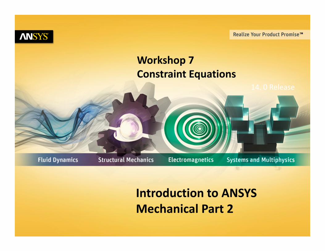
Project SchematicBegin a new Workbench session and, from the Project page, choose “Restore Archive . . . “ and browse to the file “WS7_ConstEqn.wbpz” and Open (location provided by instructor).
When prompted, “Save” using the default name in the same location as the archive file.
From the “Units” menu verify:• Project units are set to “Metric (kg, mm, s, ºC, mA, N, mV).• “Display Values in Project Units” is checked (on).

© 2011 ANSYS, Inc. February 13, 20125 Release 14.0
. . . Project Schematic1. From the Static Structural system double click
(or RMB > Edit) the “Model” cell.
2. When Mechanical opens, verify the units are set to “Metric (mm, kg, s, mV, mA)”. 2.
1.

© 2011 ANSYS, Inc. February 13, 20126 Release 14.0
3. Highlight the Model branch in the tree.
4. Highlight the top face of the hook tip (shownhere), RMB > Insert > Remote Point.
5. Right click the new remote point and rename “Tip Point”.
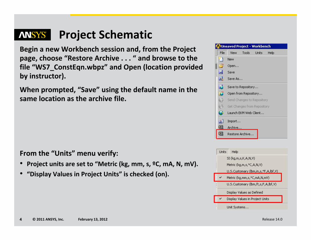
PreprocessingConstraint equations are written in terms of remote points. Before we can write the necessary expression we first need to create the remote points.
5.
4.
3.
© 2011 ANSYS, Inc. February 13, 20127 Release 14.0
. . . Preprocessing
6. Highlight the rectangular end of the hook.
7. RMB > Insert > Remote Point.
8. Right click the new remote point and rename “Press Point”.
8.
7.
6.

© 2011 ANSYS, Inc. February 13, 20128 Release 14.0
. . . Preprocessing9. Highlight the Static Structural branch, RMB >
Insert > Remote Displacement.
10. In the details for the remote displacement change the scope method to “Remote Point”.
11. In the “Remote Points” field choose the point “Press Point”.
11.
10.
9.
© 2011 ANSYS, Inc. February 13, 20129 Release 14.0
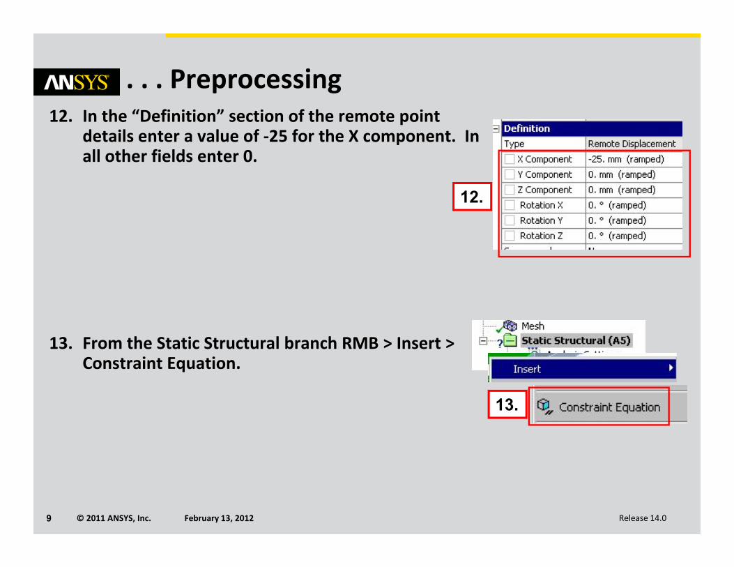
. . . Preprocessing12. In the “Definition” section of the remote point
details enter a value of ‐25 for the X component. In all other fields enter 0.
13. From the Static Structural branch RMB > Insert > Constraint Equation.
12.
13.

© 2011 ANSYS, Inc. February 13, 201210 Release 14.0
. . . Preprocessing14. In the constraint equation worksheet “RMB >
Add” to insert the first row.
15. Referring to the expression from page 5:
• Coefficient = 5
• Remote Point = “Tip Point”
• DOF Selection = Y Displacement
16. Add a second row and configure as shown below (coefficient = ‐1, remote point = “Press Point” and DOF = X displacement).
14.
15.
16.

© 2011 ANSYS, Inc. February 13, 201211 Release 14.0
Solution17. Highlight the “Analysis Settings” branch.
18. In the details change “Large Deflection” to “On”.
Since we are applying a displacement of 25 mm on the model it means the geometry will change location significantly. The large deflection option instructs the solver to track the change in location of each node. While beyond the scope of this course, the subject is covered in detail in the ANSYS Mechanical Structural Nonlinearities course.
19. Solve.
18.
19.
17.
© 2011 ANSYS, Inc. February 13, 201212 Release 14.0
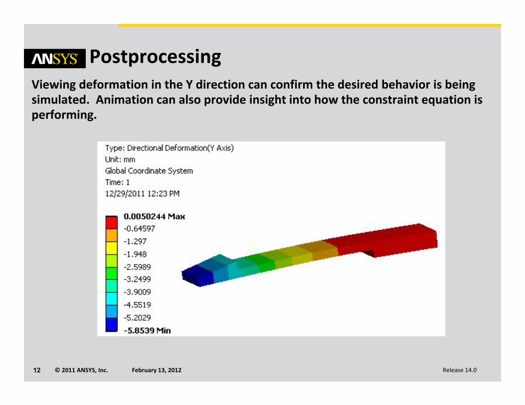
PostprocessingViewing deformation in the Y direction can confirm the desired behavior is being simulated. Animation can also provide insight into how the constraint equation is performing.