
Prof. Nizamettin AYDIN [email protected] naydin Digital Signal Processing 1.
Upload
philippa-carrCategory
view
233download
2
• What is a computer?
• in terms of what?
—Functional—Structural
Function
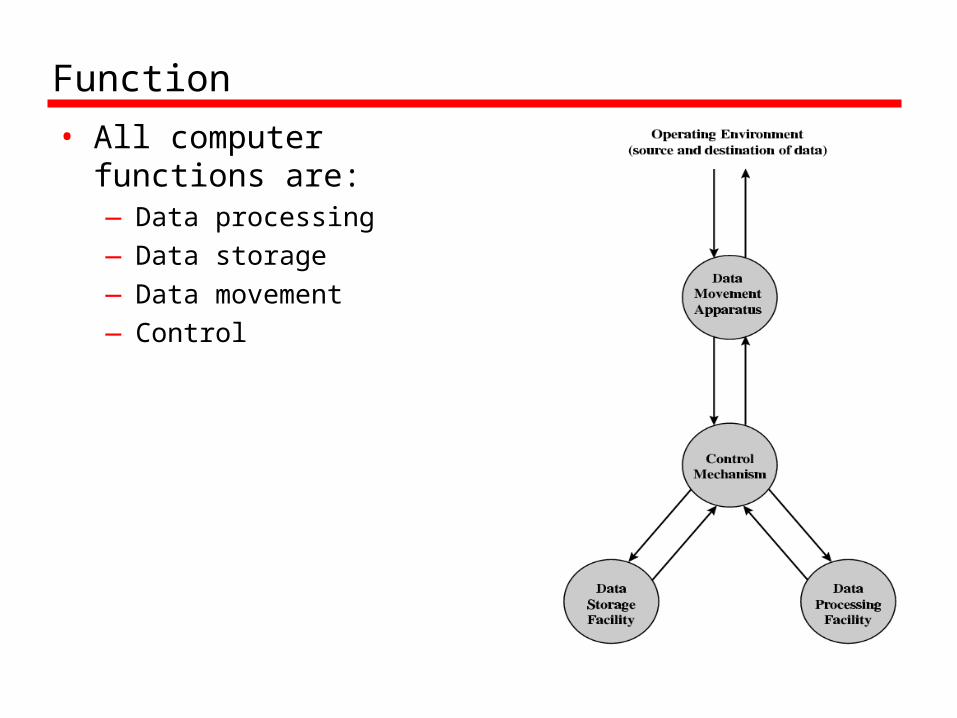
• All computer functions are:—Data processing—Data storage—Data movement—Control
Computer
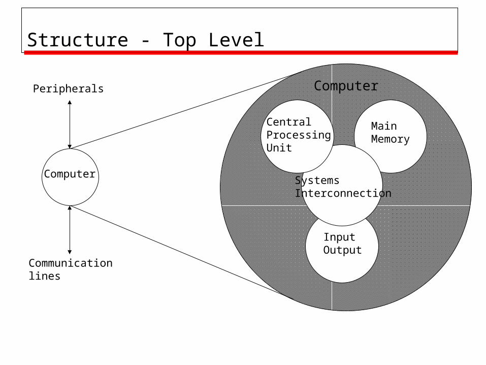
Structure - Top Level
Computer
Peripherals
Communicationlines
Main Memory
InputOutput
SystemsInterconnection
CentralProcessing Unit
CPU
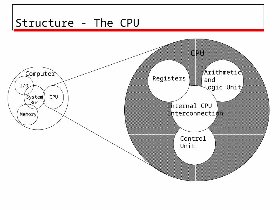
Structure - The CPU
Computer
CPU
I/O
Memory
SystemBus
Arithmeticand Logic Unit
ControlUnit
Internal CPUInterconnection
Registers
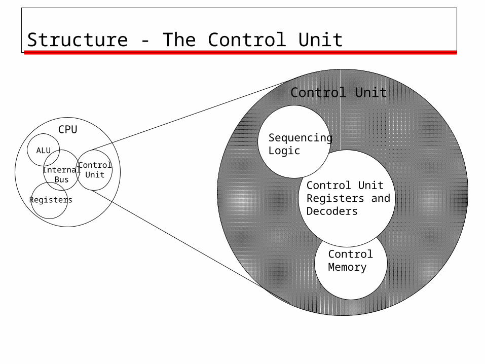
Control Unit
Structure - The Control Unit
ControlMemory
Control Unit Registers and Decoders
SequencingLogic
CPU
ControlUnit
ALU
Registers
InternalBus
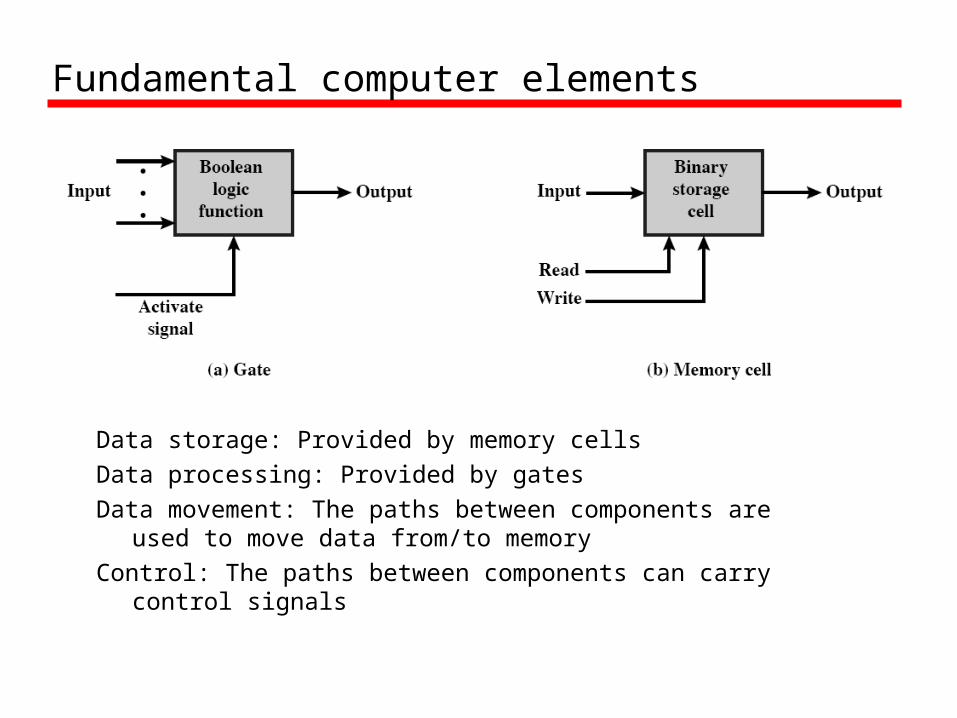
Fundamental computer elements
Data storage: Provided by memory cellsData processing: Provided by gatesData movement: The paths between components are used to
move data from/to memoryControl: The paths between components can carry control
signals
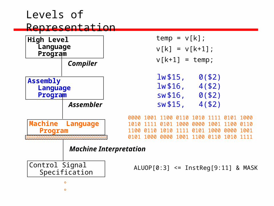
Levels of Representation
High Level Language Program
Assembly Language Program
Machine Language Program
Control Signal Specification
Compiler
Assembler
Machine Interpretation
temp = v[k];
v[k] = v[k+1];
v[k+1] = temp;
lw $15, 0($2)lw $16, 4($2)sw $16, 0($2)sw $15, 4($2)
0000 1001 1100 0110 1010 1111 0101 10001010 1111 0101 1000 0000 1001 1100 0110 1100 0110 1010 1111 0101 1000 0000 1001 0101 1000 0000 1001 1100 0110 1010 1111
°°
ALUOP[0:3] <= InstReg[9:11] & MASK
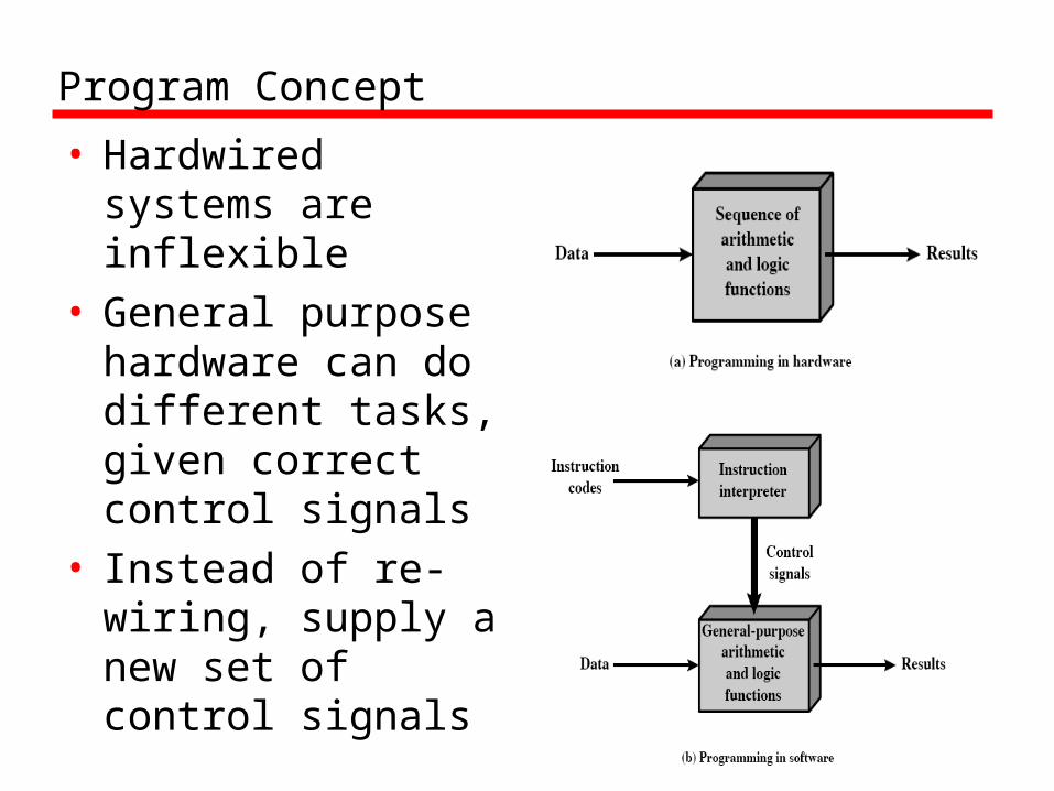
Program Concept
• Hardwired systems are inflexible
• General purpose hardware can do different tasks, given correct control signals
• Instead of re-wiring, supply a new set of control signals
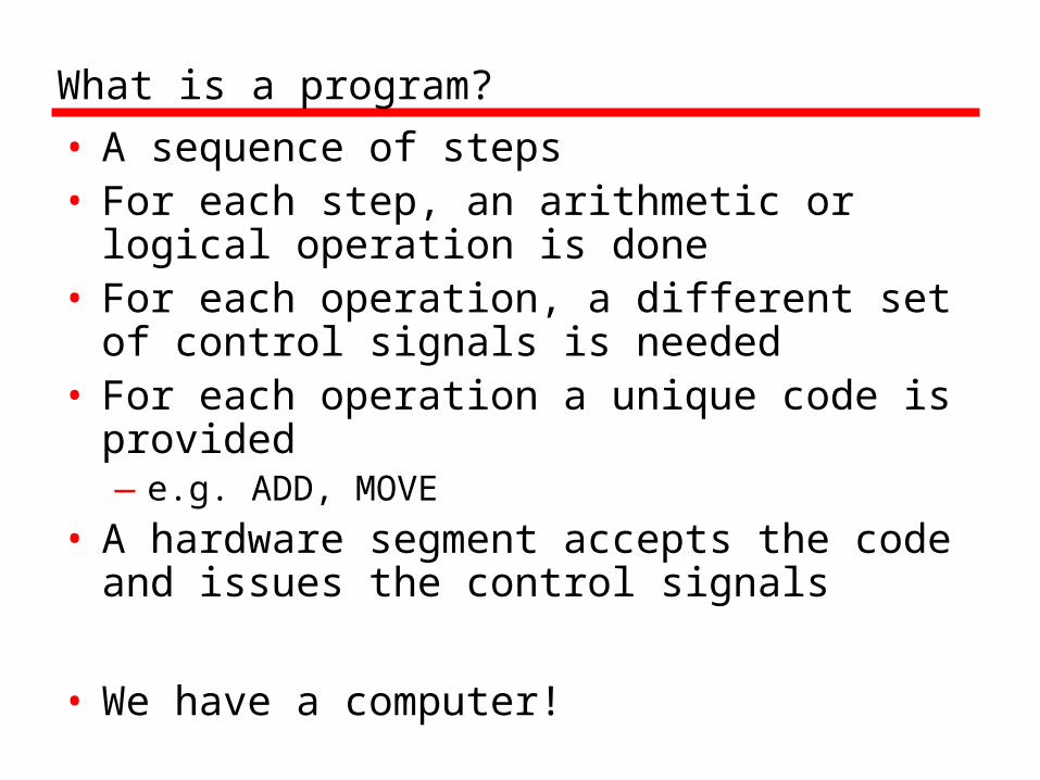
What is a program?
• A sequence of steps• For each step, an arithmetic or logical
operation is done• For each operation, a different set of
control signals is needed• For each operation a unique code is
provided—e.g. ADD, MOVE
• A hardware segment accepts the code and issues the control signals
• We have a computer!

Components
• The Control Unit and the Arithmetic and Logic Unit constitute the Central Processing Unit
• Data and instructions need to get into the system and results out—Input/output
• Temporary storage of code and results is needed—Main memory
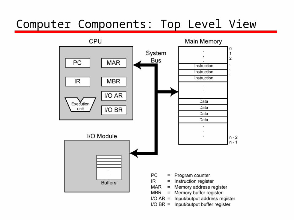
Computer Components: Top Level View

CPU Structure
• CPU must:—Fetch instructions—Interpret instructions—Fetch data—Process data—Write data
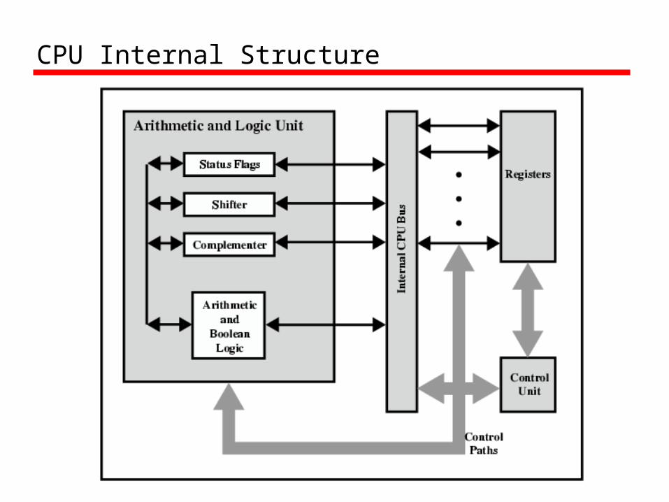
CPU Internal Structure
Registers
• CPU must have some working space (temporary storage)
• Called registers• Number and function vary between
processor designs• One of the major design decisions• Top level of memory hierarchy

Registers in the P perform two roles:
• User-visible registers—Enable the machine- or assembly language
programmer to minimize main memory references by optimizing use of registers
• Control and status registers—Used by the control unit to control the
operation of the processor and by priviliged, operating system programs to control the execution of programs

User Visible Registers
• General Purpose registers
• Data registers
• Address registers
• Condition Codes (flags)
Condition Code Registers
• Sets of individual bits—e.g. result of last operation was zero
• Can be read (implicitly) by programs—e.g. Jump if zero
• Can not (usually) be set by programs
Control & Status Registers
• Program Counter (PC)—Contains the address of an instruction to be fetched
• Instruction Decoding Register (IR) —Contains the instruction most recently fetched
• Memory Address Register (MAR)—Contains the addres of location in memory
• Memory Buffer Register (MBR) —Contains a word or data to be written to memory or
the word most recently read
Program Status Word• A set of bits containing status information• Includes Condition Codes (flags)
—Sign– sign of last result
—Zero – set when the result is 0
—Carry– set if an operation resulted in a carry (addition)
into or borrow (subtraction) out of a high order bit—Equal
– set if a logical compare result is equality—Overflow
– used to indicate arithmetic overflow—Interrupt enable/disable
– used to enable or disable interrupts
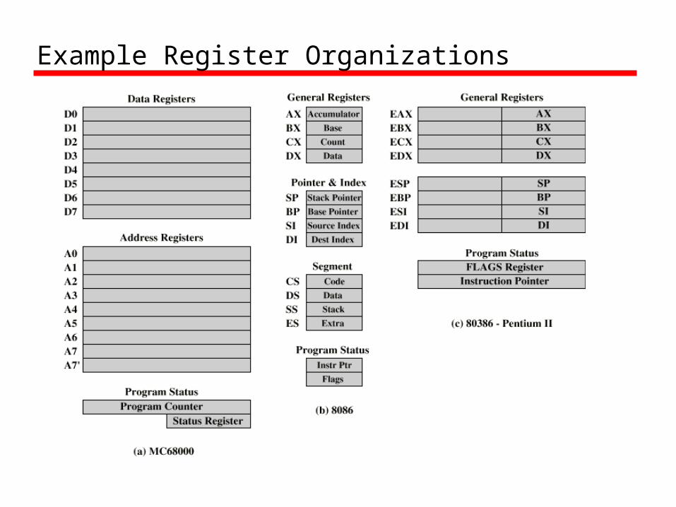
Example Register Organizations

Computer Components: Top Level View

Operation of Memory
• Each memory location has a unique address• Address from an instruction is copied to the MAR
which finds the location in memory• CPU determines if it is a store or retrieval• Transfer takes place between the MDR and
memory• MDR is a two way register
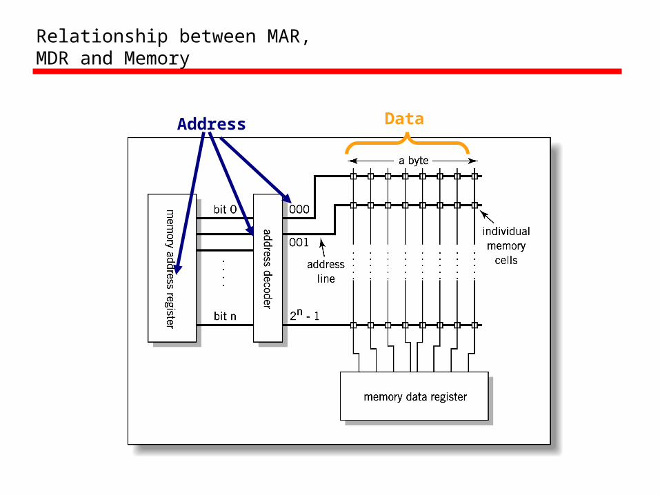
Relationship between MAR, MDR and Memory
Address
Data
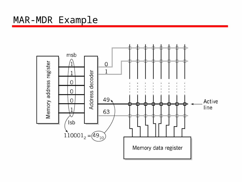
MAR-MDR Example
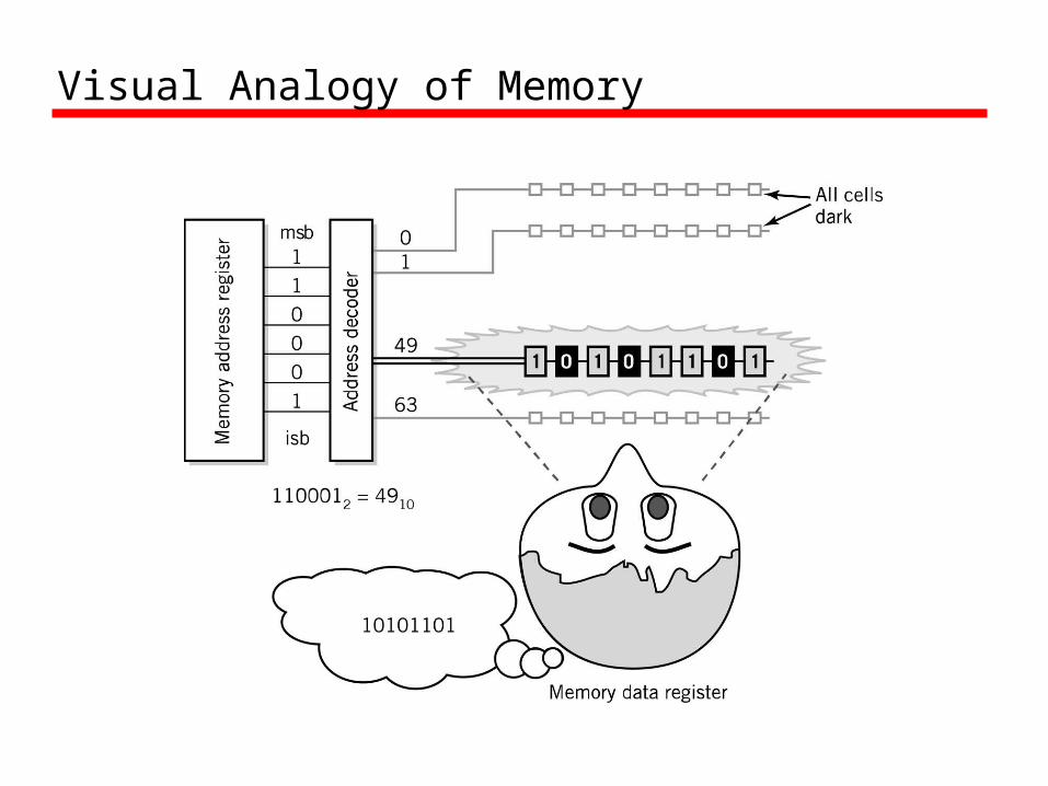
Visual Analogy of Memory

Individual Memory Cell
Memory Capacity• Determined by two factors
1. Number of bits in the MAR – 2K where K = width of the register in bits
2. Size of the address portion of the instruction– 4 bits allows 16 locations– 8 bits allows 256 locations– 32 bits allows 4,294,967,296 or 4 GB
• Important for performance—Insufficient memory can cause a processor to work at
50% below performance
RAM: Random Access Memory
• DRAM (Dynamic RAM)—Most common, cheap—Volatile: must be refreshed (recharged with power)
1000’s of times each second
• SRAM (static RAM)—Faster than DRAM and more expensive than DRAM—Volatile—Frequently small amount used in cache memory for
high-speed access used
ROM - Read Only Memory• Non-volatile memory to hold software that is not
expected to change over the life of the system• Magnetic core memory• EEPROM
—Electrically Erasable Programmable ROM—Slower and less flexible than Flash ROM
• Flash ROM —Faster than disks but more expensive—Uses
– BIOS: initial boot instructions and diagnostics– Digital cameras
Bus•The physical connection that makes it possible to
transfer data from one location in the computer system to another
•Group of electrical conductors for carrying signals from one location to another—Line: each conductor in the bus
•4 kinds of signals1.Data (alphanumeric, numerical, instructions)2.Addresses3.Control signals4.Power (sometimes)
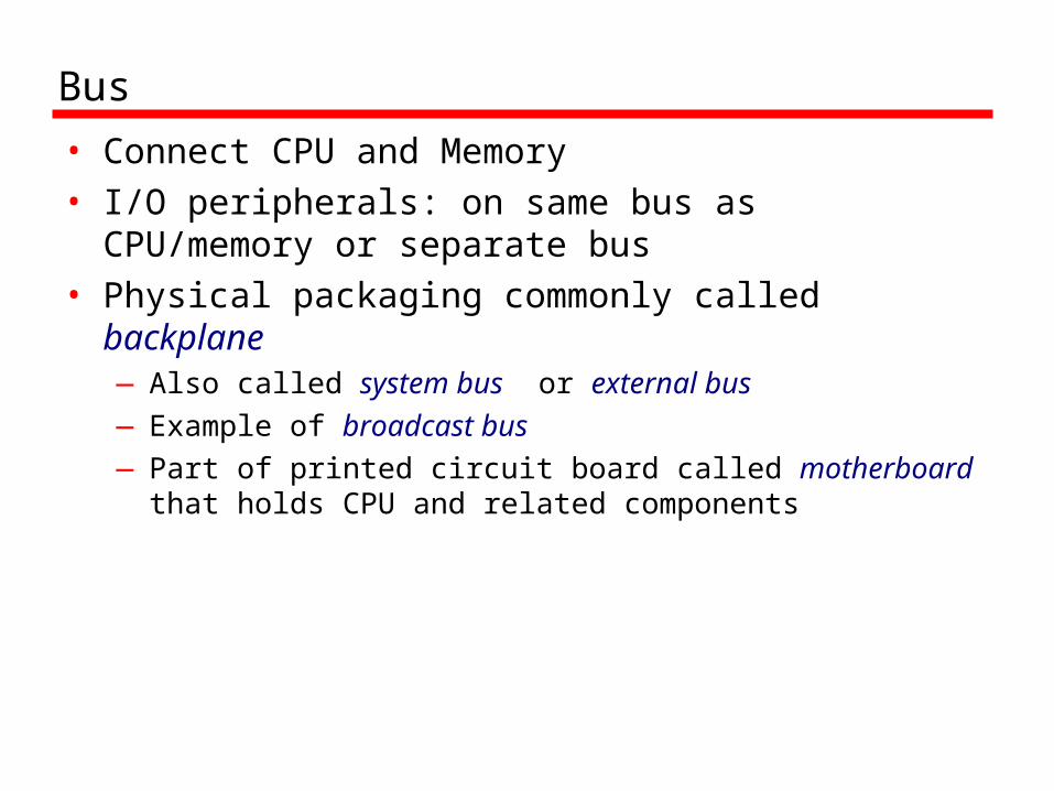
Bus
• Connect CPU and Memory• I/O peripherals: on same bus as CPU/memory or
separate bus• Physical packaging commonly called backplane
—Also called system bus or external bus—Example of broadcast bus—Part of printed circuit board called motherboard that
holds CPU and related components

Bus Characteristics
• Protocol—Documented agreement for communication—Specification that spells out the meaning of
each line and each signal on each line
• Throughput, i.e., data transfer rate in bits per second
• Data width in bits carried simultaneously
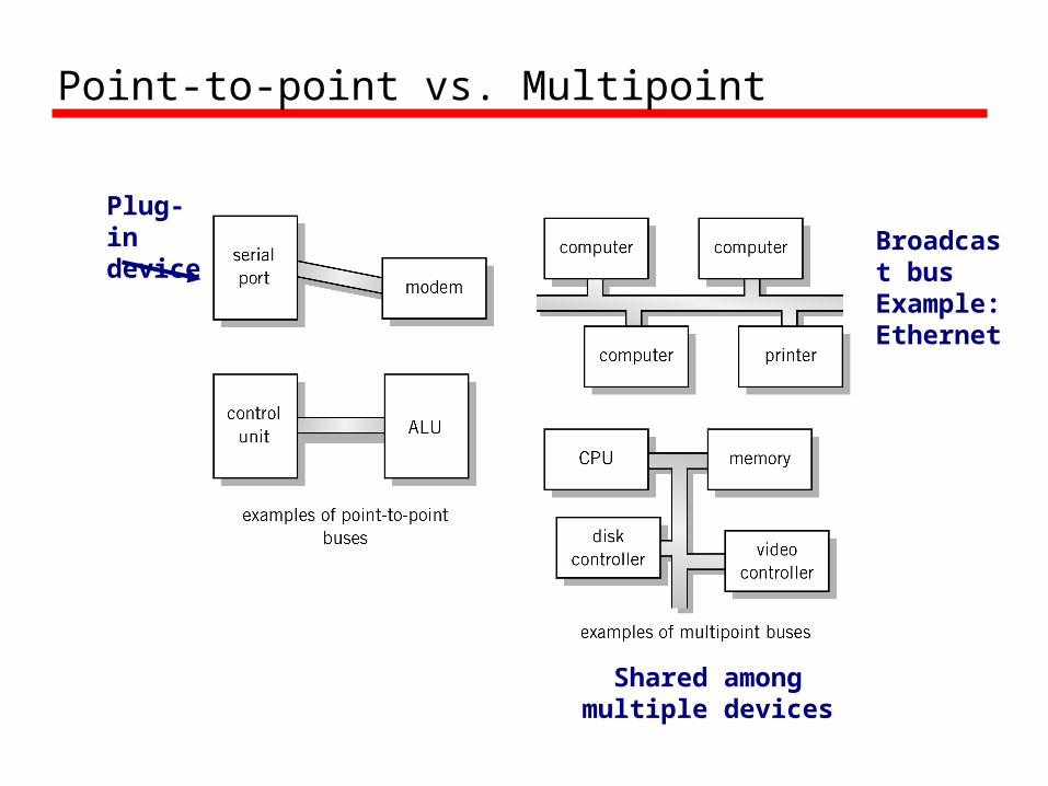
Point-to-point vs. Multipoint
Broadcast bus Example: Ethernet
Plug-in device
Shared among multiple devices

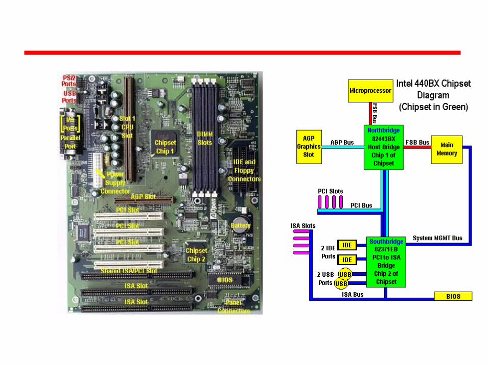
Motherboard• Printed circuit board that holds CPU and related
components including backplane
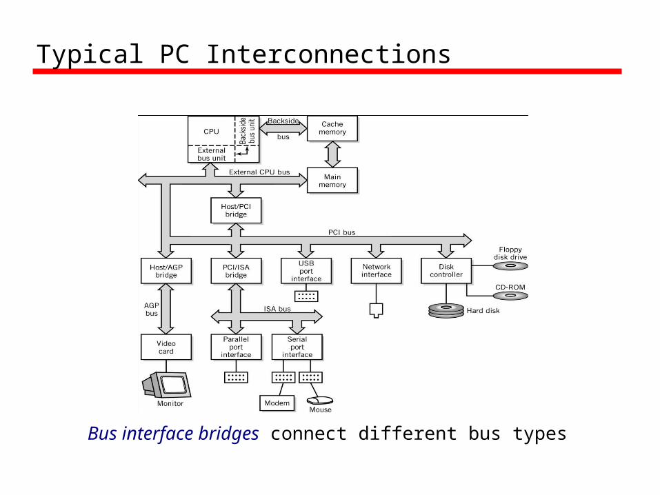
Typical PC Interconnections
Bus interface bridges connect different bus types
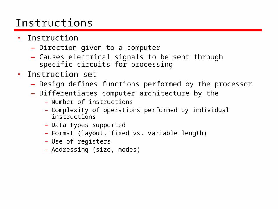
Instructions• Instruction
— Direction given to a computer— Causes electrical signals to be sent through specific circuits for
processing• Instruction set
— Design defines functions performed by the processor— Differentiates computer architecture by the
– Number of instructions– Complexity of operations performed by individual instructions– Data types supported– Format (layout, fixed vs. variable length)– Use of registers– Addressing (size, modes)
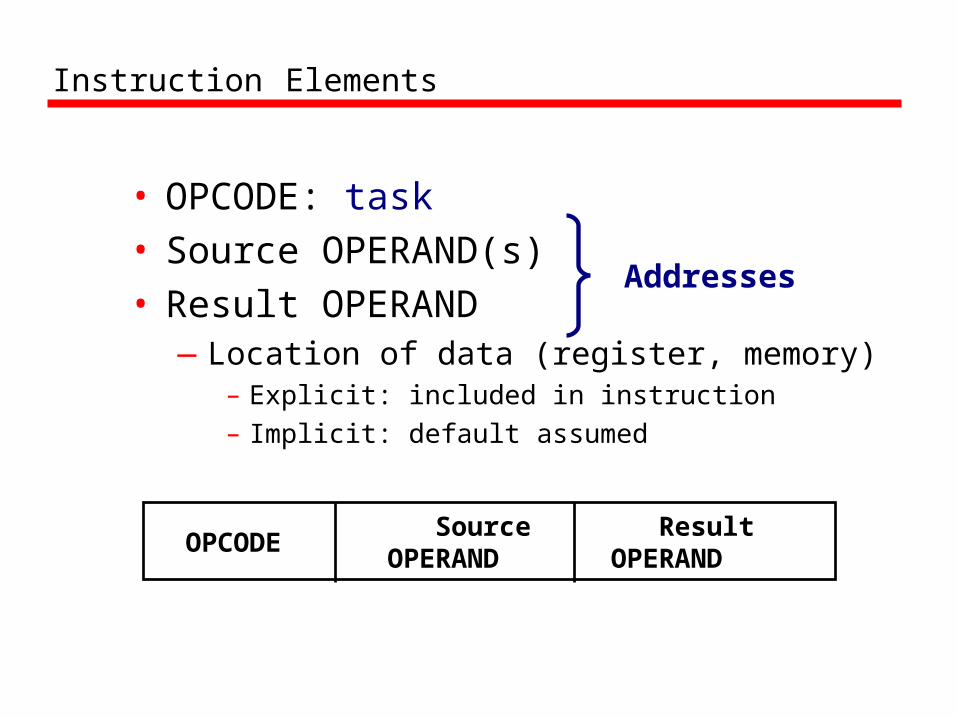
Instruction Elements
• OPCODE: task• Source OPERAND(s)• Result OPERAND
—Location of data (register, memory)– Explicit: included in instruction– Implicit: default assumed
OPCODE SourceOPERAND
Result OPERAND
Addresses
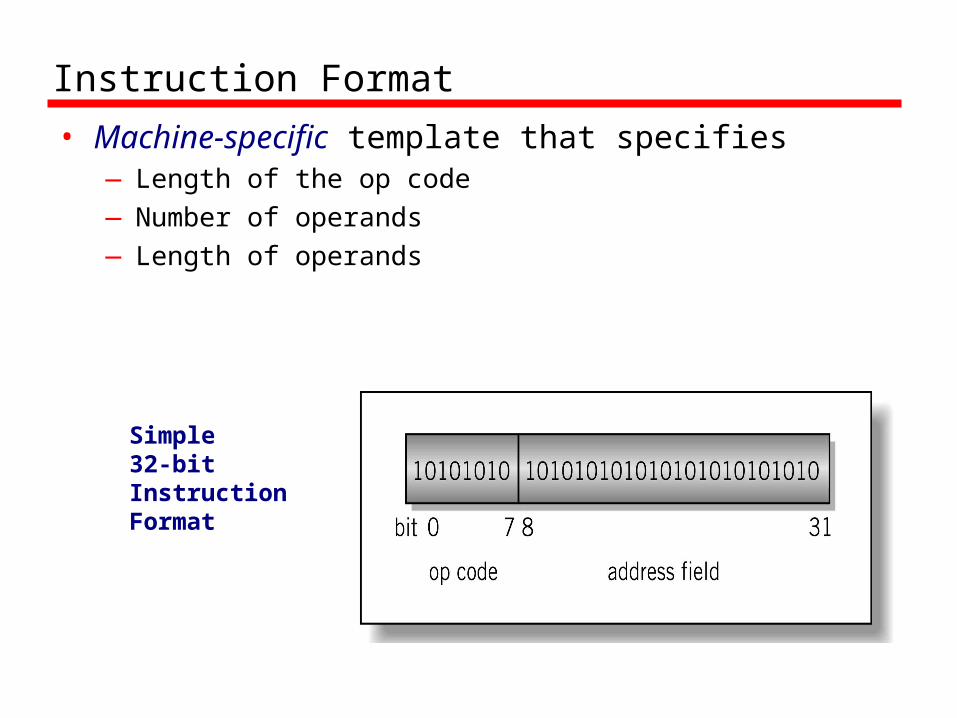
Instruction Format
• Machine-specific template that specifies—Length of the op code —Number of operands—Length of operands
Simple 32-bit Instruction Format
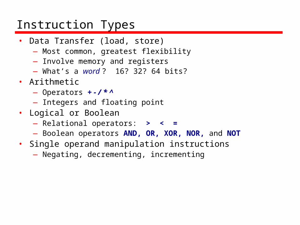
Instruction Types• Data Transfer (load, store)
— Most common, greatest flexibility— Involve memory and registers— What’s a word ? 16? 32? 64 bits?
• Arithmetic— Operators + - / * ^— Integers and floating point
• Logical or Boolean — Relational operators: > < = — Boolean operators AND, OR, XOR, NOR, and NOT
• Single operand manipulation instructions— Negating, decrementing, incrementing
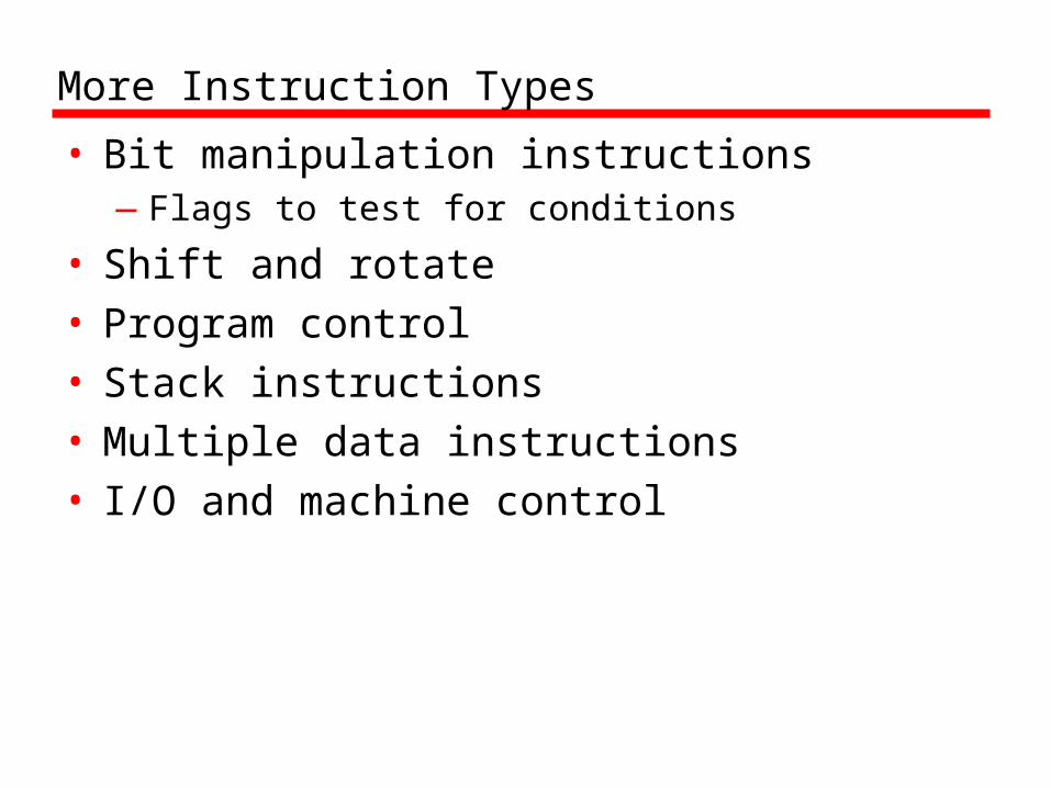
More Instruction Types
• Bit manipulation instructions—Flags to test for conditions
• Shift and rotate• Program control• Stack instructions• Multiple data instructions• I/O and machine control

Register Shifts and Rotates

Program Control Instructions
• Program control—Jump and branch—Subroutine call
and return

Instruction Cycle
• Two steps:—Fetch—Execute
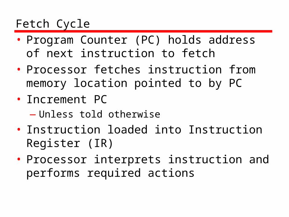
Fetch Cycle• Program Counter (PC) holds address of
next instruction to fetch• Processor fetches instruction from memory
location pointed to by PC• Increment PC
—Unless told otherwise
• Instruction loaded into Instruction Register (IR)
• Processor interprets instruction and performs required actions

Execute Cycle• Processor-memory
—data transfer between CPU and main memory
• Processor I/O—Data transfer between CPU and I/O module
• Data processing—Some arithmetic or logical operation on data
• Control—Alteration of sequence of operations—e.g. jump
• Combination of above
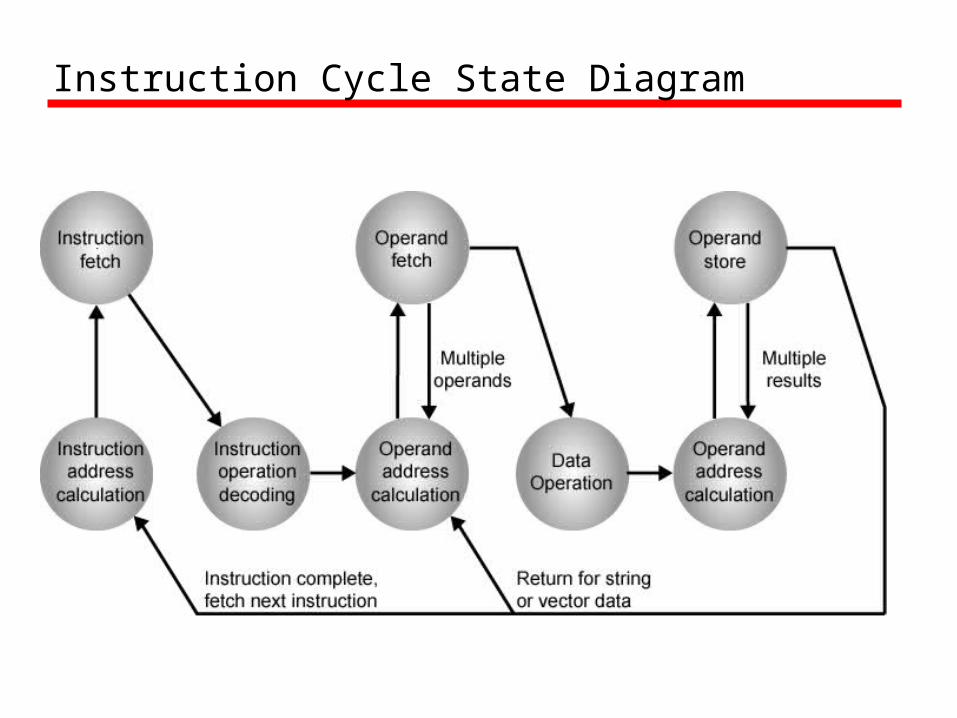
Instruction Cycle State Diagram
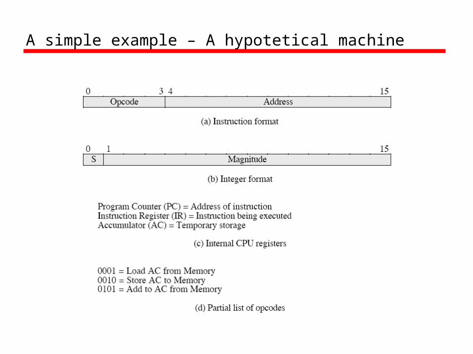
A simple example – A hypotetical machine
A simple example –
• Next figure illustrates a partial program execution.
• It adds the contents of the memory word at address 940 to the contents of the memory word at address 941 and stores the result in the address 941.
• Here 3 instructions (3 fetch and 3 execute cycles) are required

Example of Program Execution

von Neumann Architecture (1945)
• Stored program concept• Memory is addressed linearly• Memory is addressed without regard to
content
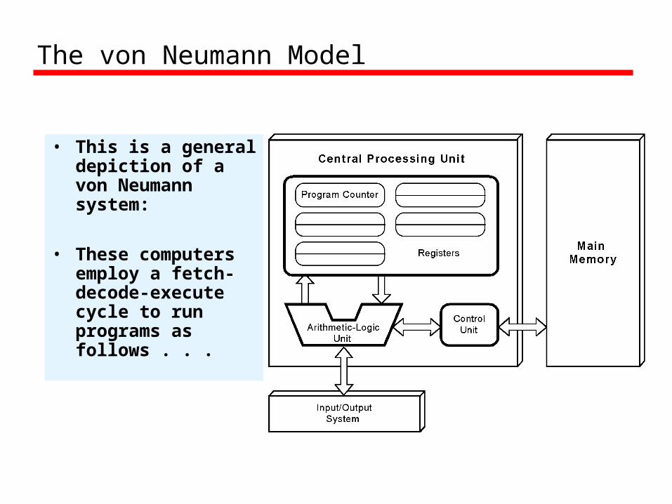
• This is a general depiction of a von Neumann system:
• These computers employ a fetch-decode-execute cycle to run programs as follows . . .
The von Neumann Model

• The control unit fetches the next instruction from memory using the program counter to determine where the instruction is located.
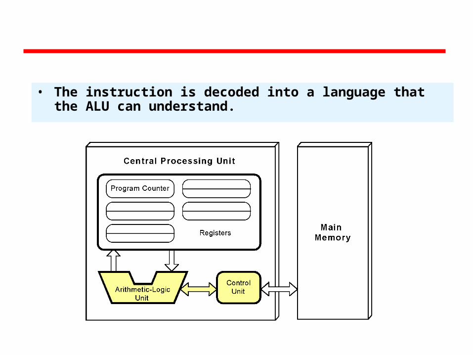
• The instruction is decoded into a language that the ALU can understand.
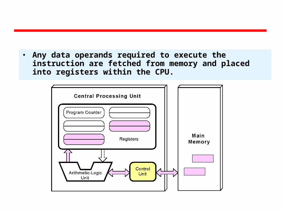
• Any data operands required to execute the instruction are fetched from memory and placed into registers within the CPU.
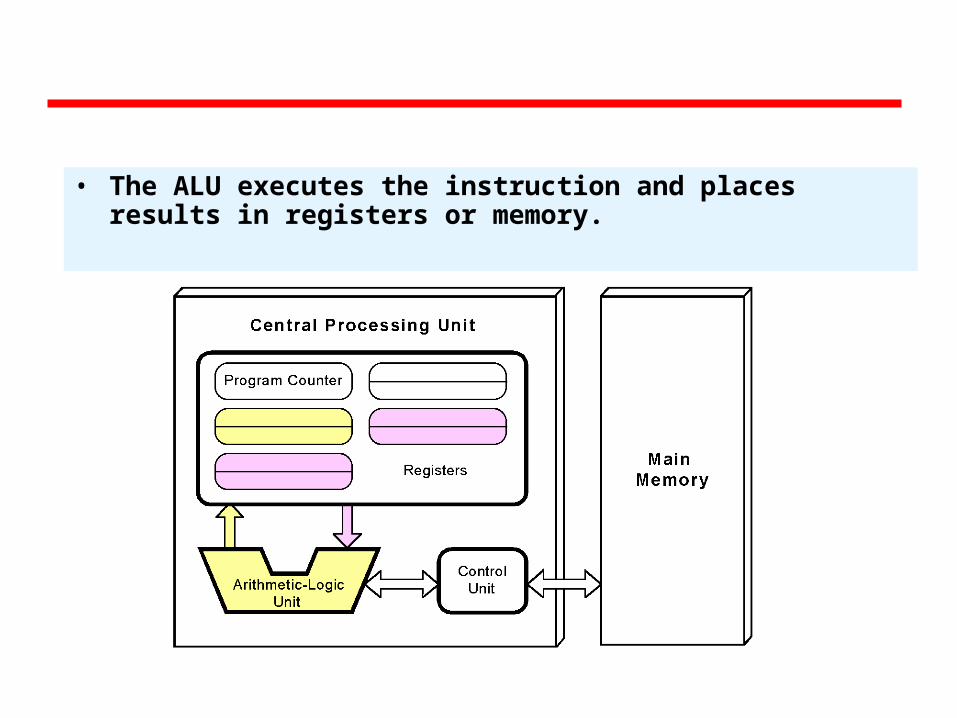
• The ALU executes the instruction and places results in registers or memory.
A virtual processor for understanding instruction cycle
The VVM Machine
• The Visible Virtual Machine (VVM) is based on a model of a simple computer device called the Little Man Computer which was originally developed by Stuart Madnick in 1965, and revised in 1979.
• The VVM is a virtual machine because it only appears to be a functioning hardware device.
• In reality, the VVM "hardware" is created through a software simulation. One important simplifying feature of this machine is that it works in decimal rather than in the traditional binary number system.
• Also, the VVM works with only one form of data - decimal integers.

Hardware Components of VVM• I/O Log. This represents the system console which shows
the details of relevant events in the execution of the program. Examples of events are the program begins, the program aborts, or input or output is generated.
• Accumulator Register (Accum). This register holds the values used in arithmetic and logical computations. It also serves as a buffer between input/output and memory. Legitimate values are any integer between -999 and +999. Values outside of this range will cause a fatal VVM Machine error. Non integer values are converted to integers before being loaded into the register.
• Instruction Cycle Display. This shows the number of instructions that have been executed since the current program execution began.
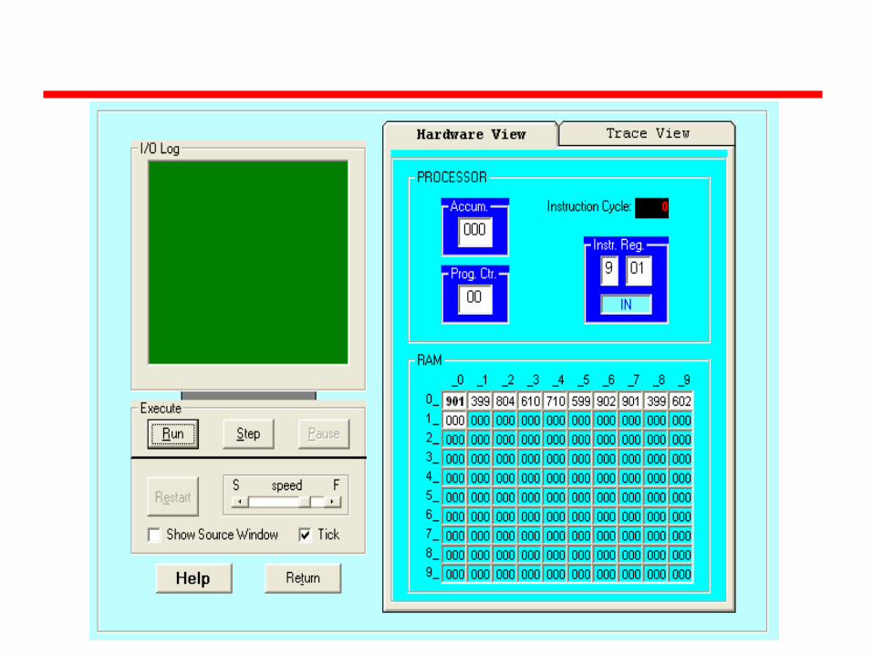
Hardware Components of VVM
• Instruction Register (Instr. Reg.). This register holds the next instruction to be executed. The register is divided into two parts: a one-digit operation code, and a two digit operand. The Assembly Language mnemonic code for the operation code is displayed below the register.
• Program Counter Register (Prog. Ctr.). The two-digit integer value in this register "points" to the next instruction to be fetched from RAM. Most instructions increment this register during the execute phase of the instruction cycle. Legitimate values range from 00 to 99. A value beyond this range causes a fatal VVM Machine error.
• RAM. The 100 data-word Random Access Storage is shown as a matrix of ten rows and ten columns. The two-digit memory addresses increase sequentially across the rows and run from 00 to 99. Each storage location can hold a three-digit integer value between -999 and +999.
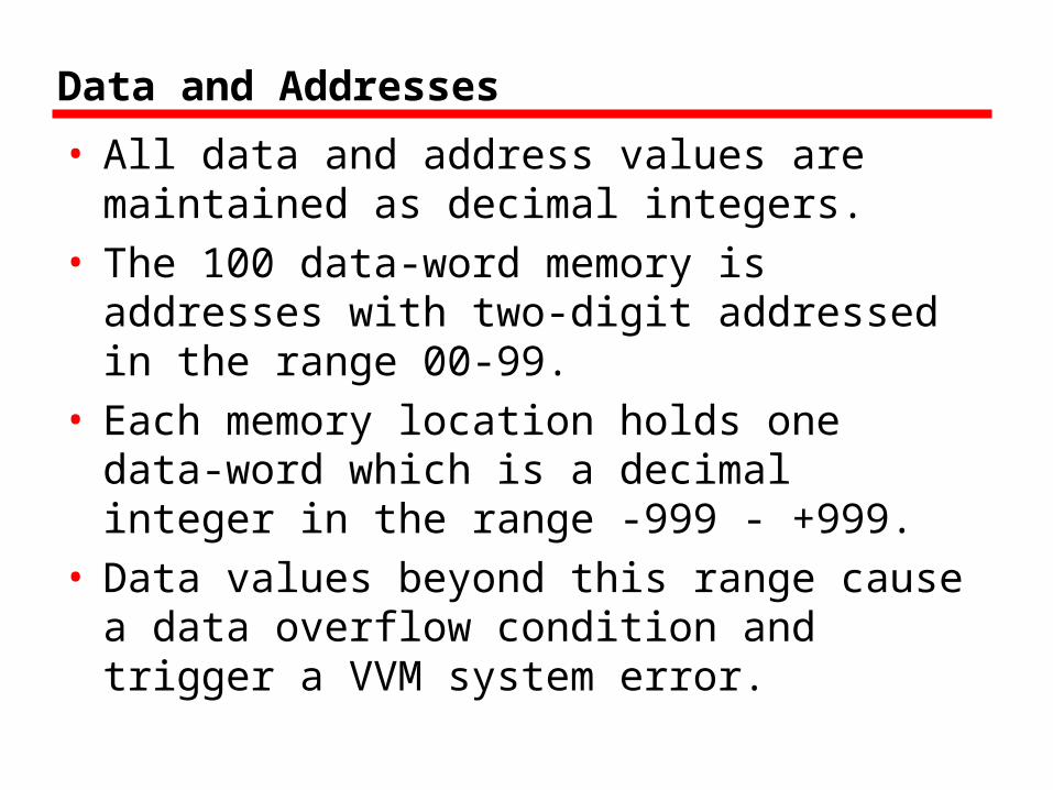
Data and Addresses
• All data and address values are maintained as decimal integers.
• The 100 data-word memory is addresses with two-digit addressed in the range 00-99.
• Each memory location holds one data-word which is a decimal integer in the range -999 - +999.
• Data values beyond this range cause a data overflow condition and trigger a VVM system error.

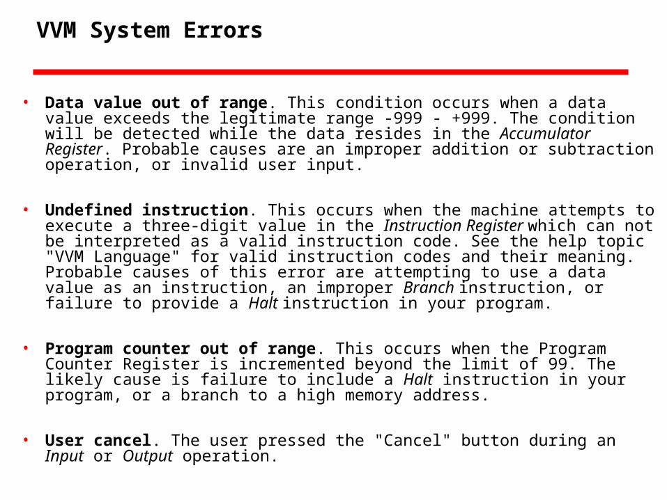
VVM System Errors
• Data value out of range. This condition occurs when a data value exceeds the legitimate range -999 - +999. The condition will be detected while the data resides in the Accumulator Register. Probable causes are an improper addition or subtraction operation, or invalid user input.
• Undefined instruction. This occurs when the machine attempts to execute a three-digit value in the Instruction Register which can not be interpreted as a valid instruction code. See the help topic "VVM Language" for valid instruction codes and their meaning. Probable causes of this error are attempting to use a data value as an instruction, an improper Branch instruction, or failure to provide a Halt instruction in your program.
• Program counter out of range. This occurs when the Program Counter Register is incremented beyond the limit of 99. The likely cause is failure to include a Halt instruction in your program, or a branch to a high memory address.
• User cancel. The user pressed the "Cancel" button during an Input or Output operation.
The Language Instructions
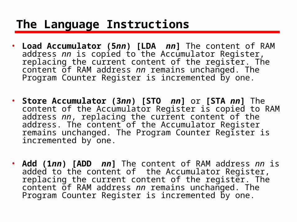
• Load Accumulator (5nn) [LDA nn] The content of RAM address nn is copied to the Accumulator Register, replacing the current content of the register. The content of RAM address nn remains unchanged. The Program Counter Register is incremented by one.
• Store Accumulator (3nn) [STO nn] or [STA nn] The content of the Accumulator Register is copied to RAM address nn, replacing the current content of the address. The content of the Accumulator Register remains unchanged. The Program Counter Register is incremented by one.
• Add (1nn) [ADD nn] The content of RAM address nn is added to the content of the Accumulator Register, replacing the current content of the register. The content of RAM address nn remains unchanged. The Program Counter Register is incremented by one.

The Language Instructions
• Subtract (2nn) [SUB nn] The content of RAM address nn is subtracted from the content of the Accumulator Register, replacing the current content of the register. The content of RAM address nn remains unchanged. The Program Counter Register is incremented by one.
• Input (901) [IN] or [INP] A value input by the user is stored in the Accumulator Register, replacing the current content of the register. Note that the two-digit operand does not represent an address in this instruction, but rather specifies the particulars of the I/O operation (see Output). The operand value can be omitted in the Assembly Language format. The Program Counter Register is incremented by one with this instruction.
• Output (902) [OUT] or [PRN] The content of the Accumulator Register is output to the user. The current content of the register remains unchanged. Note that the two-digit operand does not represent an address in this instruction, but rather specifies the particulars of the I/O operation (see Input). The operand value can be omitted in the Assembly Language format. The Program Counter Register is incremented by one with this instruction.
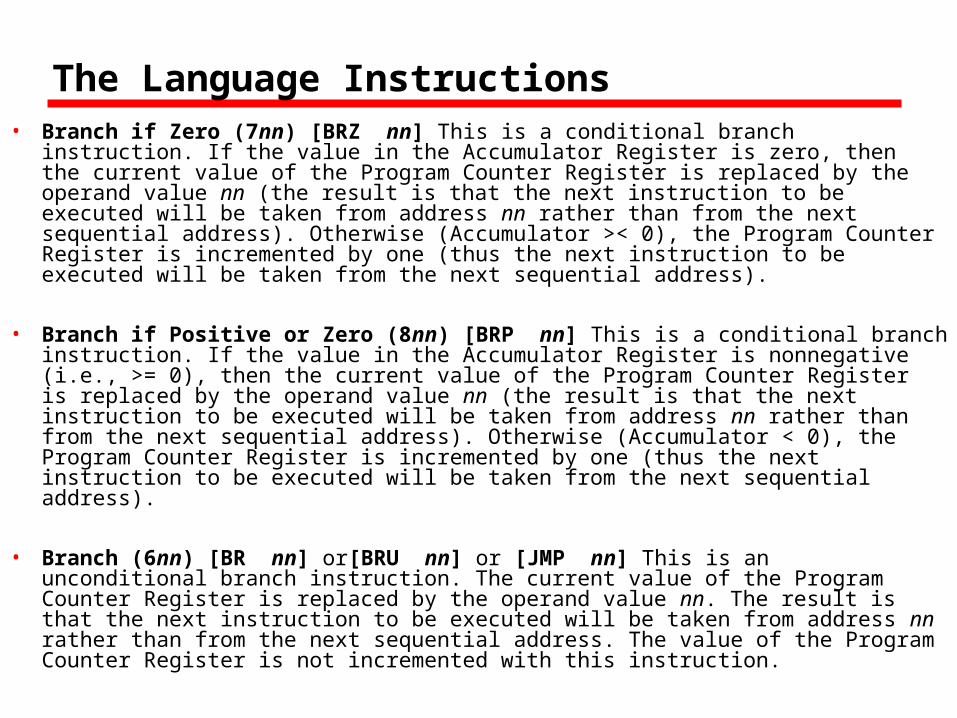
The Language Instructions• Branch if Zero (7nn) [BRZ nn] This is a conditional branch instruction. If
the value in the Accumulator Register is zero, then the current value of the Program Counter Register is replaced by the operand value nn (the result is that the next instruction to be executed will be taken from address nn rather than from the next sequential address). Otherwise (Accumulator >< 0), the Program Counter Register is incremented by one (thus the next instruction to be executed will be taken from the next sequential address).
• Branch if Positive or Zero (8nn) [BRP nn] This is a conditional branch instruction. If the value in the Accumulator Register is nonnegative (i.e., >= 0), then the current value of the Program Counter Register is replaced by the operand value nn (the result is that the next instruction to be executed will be taken from address nn rather than from the next sequential address). Otherwise (Accumulator < 0), the Program Counter Register is incremented by one (thus the next instruction to be executed will be taken from the next sequential address).
• Branch (6nn) [BR nn] or[BRU nn] or [JMP nn] This is an unconditional branch instruction. The current value of the Program Counter Register is replaced by the operand value nn. The result is that the next instruction to be executed will be taken from address nn rather than from the next sequential address. The value of the Program Counter Register is not incremented with this instruction.
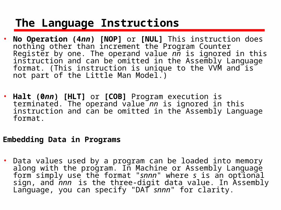
The Language Instructions• No Operation (4nn) [NOP] or [NUL] This instruction does
nothing other than increment the Program Counter Register by one. The operand value nn is ignored in this instruction and can be omitted in the Assembly Language format. (This instruction is unique to the VVM and is not part of the Little Man Model.)
• Halt (0nn) [HLT] or [COB] Program execution is terminated. The operand value nn is ignored in this instruction and can be omitted in the Assembly Language format.
Embedding Data in Programs
• Data values used by a program can be loaded into memory along with the program. In Machine or Assembly Language form simply use the format "snnn" where s is an optional sign, and nnn is the three-digit data value. In Assembly Language, you can specify "DAT snnn" for clarity.
The Little Man Computer
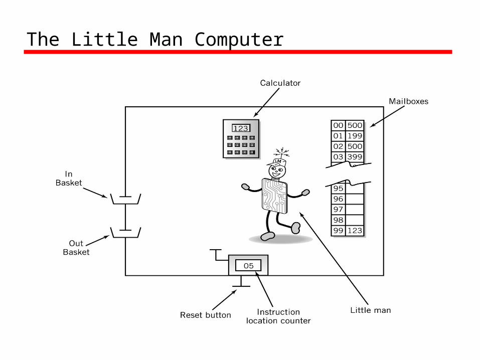
The Little Man Computer

Mailboxes: Address vs. Content
• Addresses are consecutive• Content may be
—Data or—Instructions
Address Content
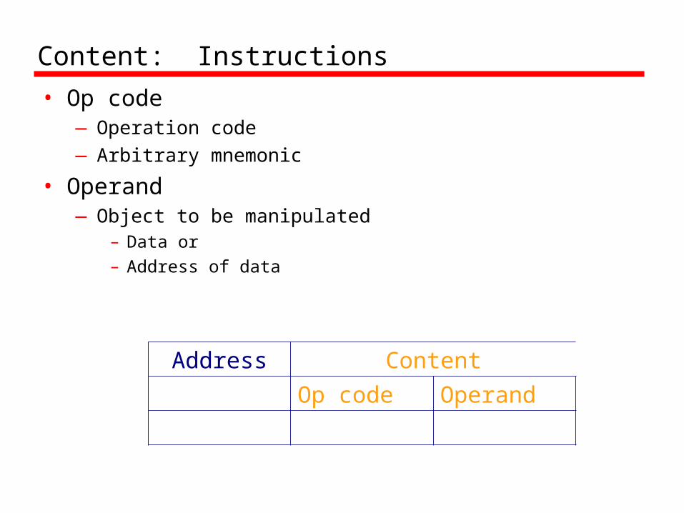
Content: Instructions
• Op code—Operation code—Arbitrary mnemonic
• Operand—Object to be manipulated
– Data or– Address of data
Address Content
Op code Operand

Magic!
• Load program into memory• Put data into In Basket
• http://www.herts.ac.uk/ltdu/projects/mm5/lmc.html
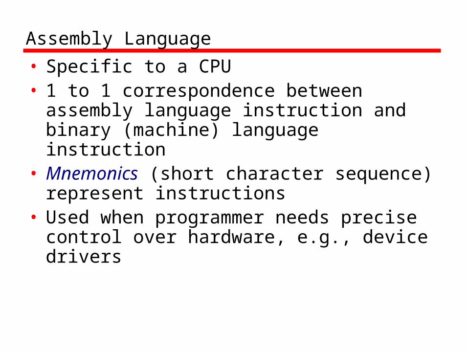
Assembly Language
• Specific to a CPU• 1 to 1 correspondence between assembly
language instruction and binary (machine) language instruction
• Mnemonics (short character sequence) represent instructions
• Used when programmer needs precise control over hardware, e.g., device drivers
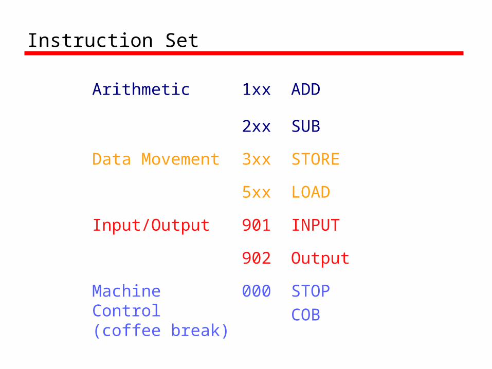
Instruction Set
Arithmetic 1xx ADD
2xx SUB
Data Movement 3xx STORE
5xx LOAD
Input/Output 901 INPUT
902 Output
Machine Control(coffee break)
000 STOPCOB
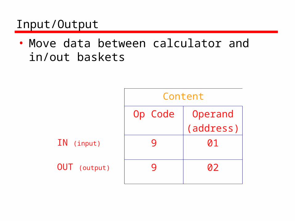
Input/Output
• Move data between calculator and in/out baskets
Content
Op Code Operand(address)
IN (input) 9 01
OUT (output) 9 02
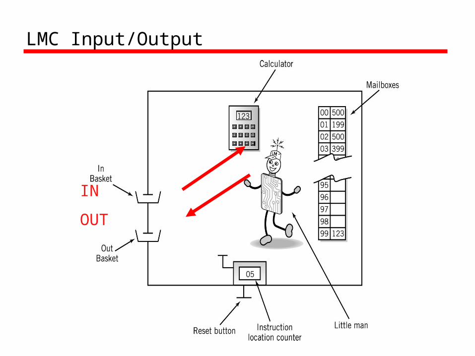
LMC Input/Output
IN
OUT
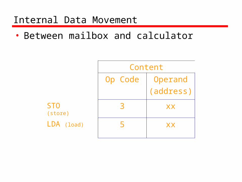
Internal Data Movement
• Between mailbox and calculator
Content
Op Code Operand(address)
STO (store) 3 xx
LDA (load) 5 xx
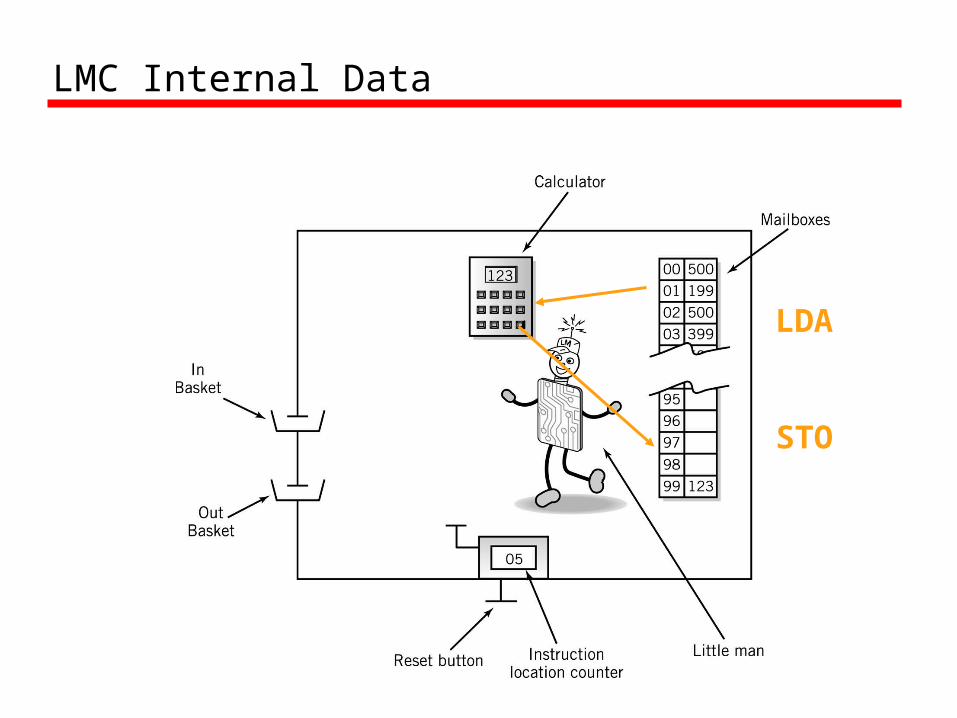
LMC Internal Data
LDA
STO

Data storage location
• Physically identical to instruction mailbox• Not located in instruction sequence• Identified by DAT mnemonic
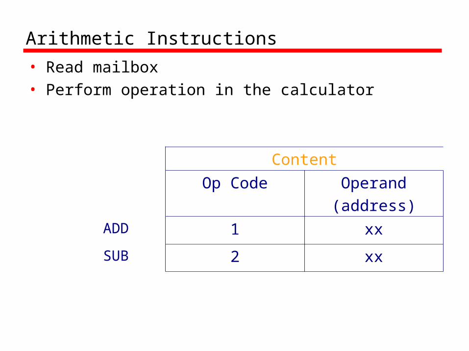
Arithmetic Instructions
• Read mailbox• Perform operation in the calculator
Content
Op Code Operand(address)
ADD 1 xx
SUB 2 xx
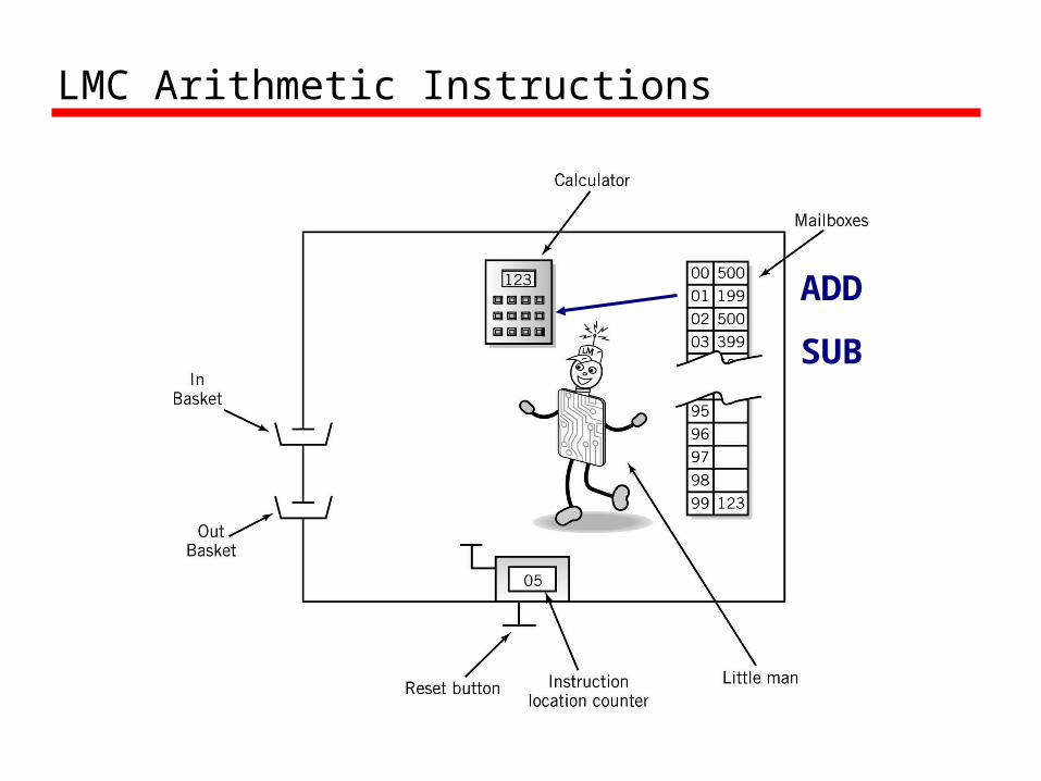
LMC Arithmetic Instructions
ADD
SUB
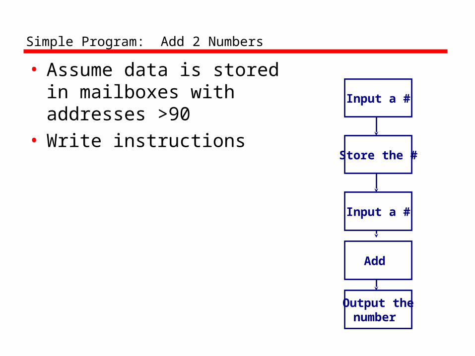
Simple Program: Add 2 Numbers
• Assume data is storedin mailboxes withaddresses >90
• Write instructions
Input a #
Store the #
Input a #
Add
Output thenumber
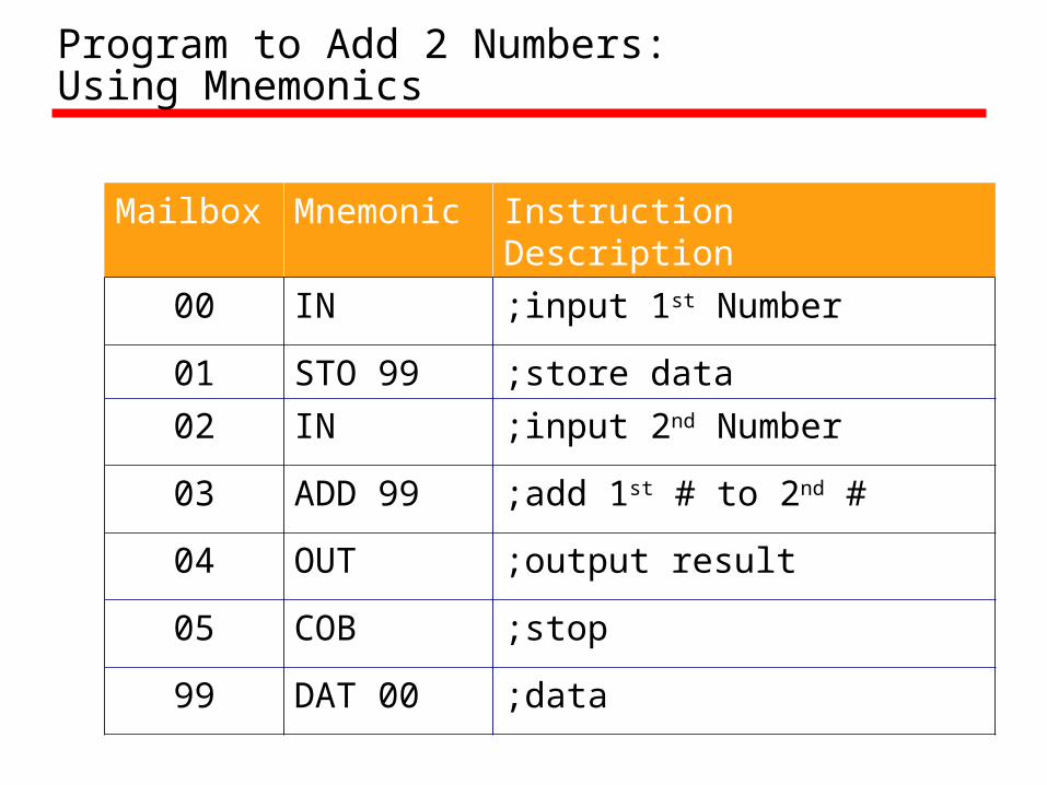
Program to Add 2 Numbers:Using Mnemonics
Mailbox Mnemonic Instruction Description
00 IN ;input 1st Number
01 STO 99 ;store data
02 IN ;input 2nd Number
03 ADD 99 ;add 1st # to 2nd #
04 OUT ;output result
05 COB ;stop
99 DAT 00 ;data
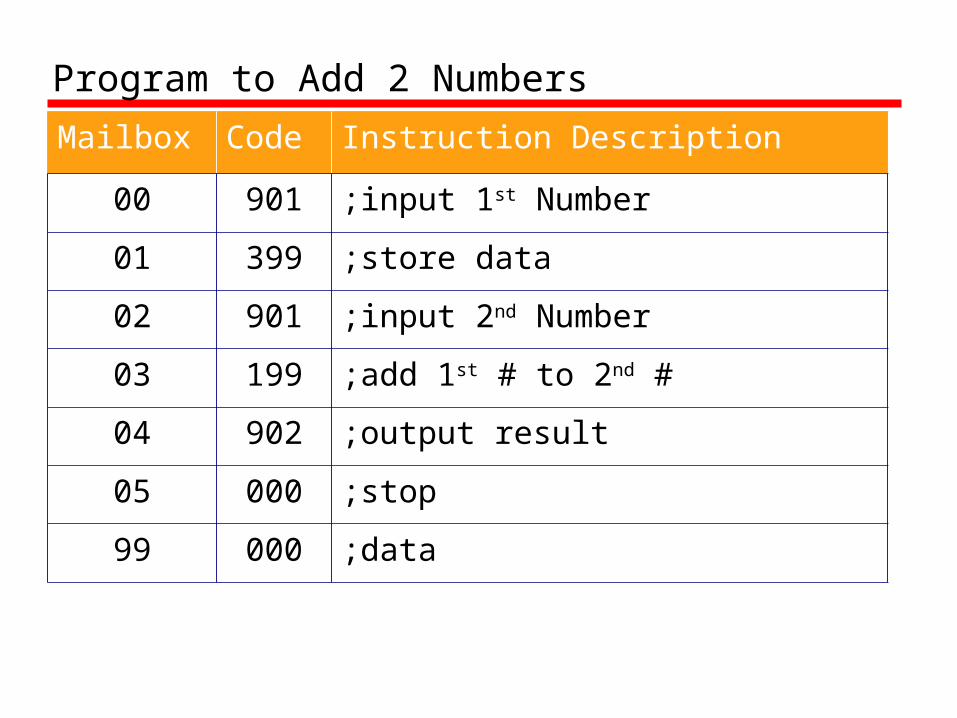
Program to Add 2 Numbers
Mailbox Code Instruction Description
00 901 ;input 1st Number
01 399 ;store data
02 901 ;input 2nd Number
03 199 ;add 1st # to 2nd #
04 902 ;output result
05 000 ;stop
99 000 ;data
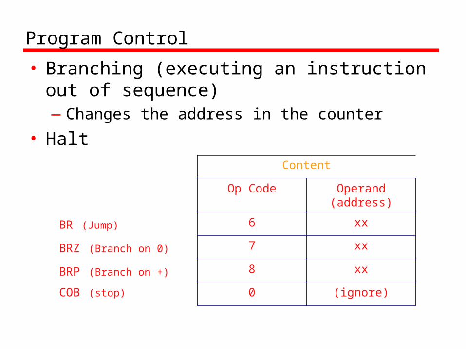
Program Control
• Branching (executing an instruction out of sequence)—Changes the address in the counter
• HaltContent
Op Code Operand(address)
BR (Jump) 6 xx
BRZ (Branch on 0) 7 xx
BRP (Branch on +) 8 xx
COB (stop) 0 (ignore)

Instruction Set
Arithmetic 1xx ADD
2xx SUB
Data Movement 3xx STORE
5xx LOAD
BR 6xx JUMP
BRZ 7xx BRANC ON 0
BRP 8xx BRANCH ON +
Input/Output 901 INPUT
902 OUTPUT
Machine Control(coffee break)
000 HALTCOB
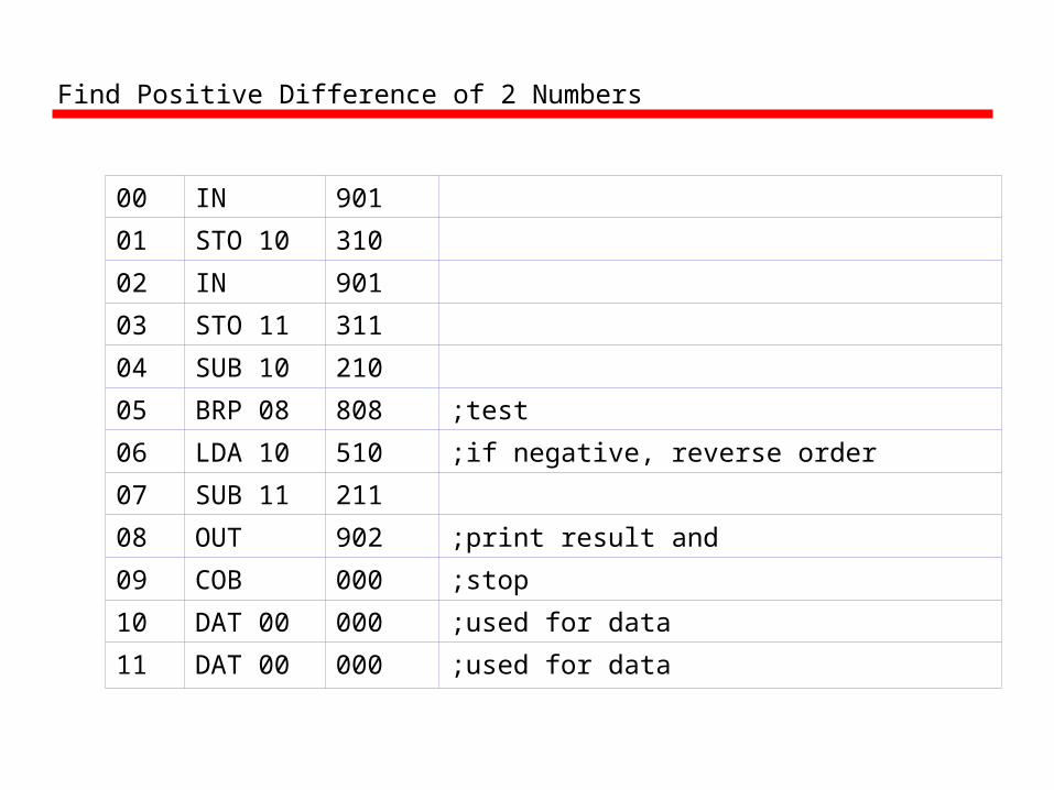
Find Positive Difference of 2 Numbers
00 IN 901
01 STO 10 310
02 IN 901
03 STO 11 311
04 SUB 10 210
05 BRP 08 808 ;test
06 LDA 10 510 ;if negative, reverse order
07 SUB 11 211
08 OUT 902 ;print result and
09 COB 000 ;stop
10 DAT 00 000 ;used for data
11 DAT 00 000 ;used for data

Instruction Cycle
• Fetch: Little Man finds out what instruction he is to execute
• Execute: Little Man performs the work.
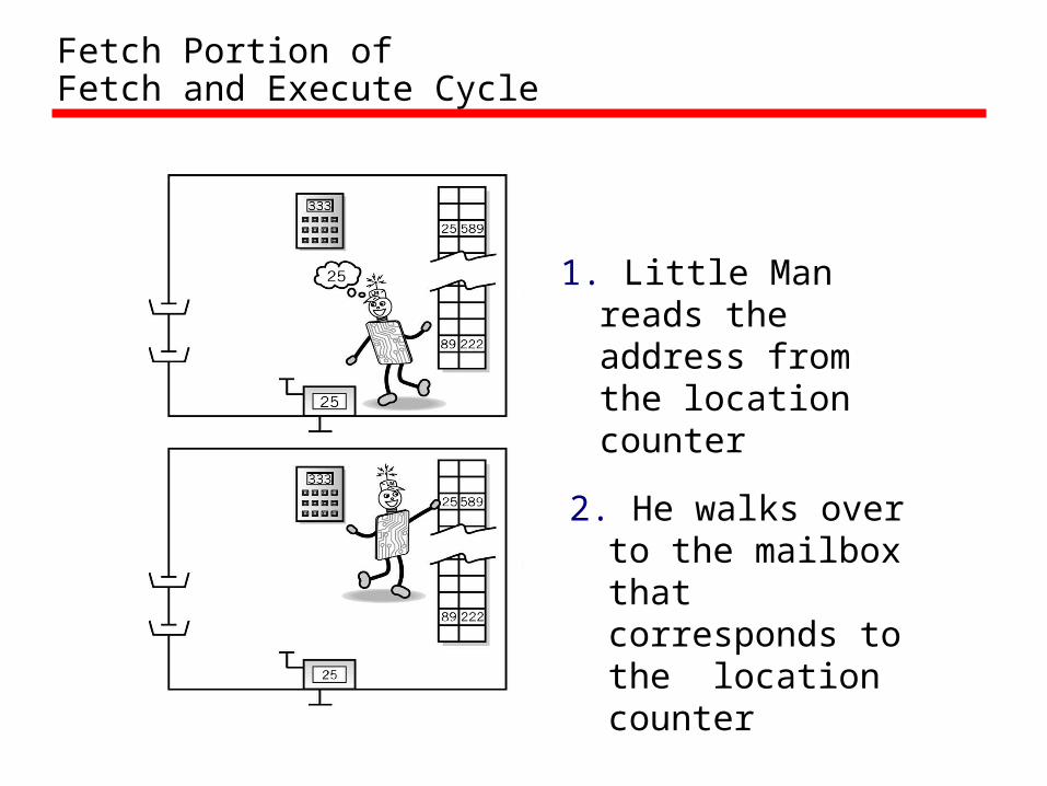
Fetch Portion ofFetch and Execute Cycle
1. Little Man reads the address from the location counter
2. He walks over to the mailbox that corresponds to the location counter
Fetch, cont.
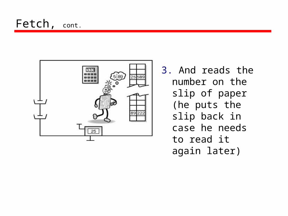
3. And reads the number on the slip of paper (he puts the slip back in case he needs to read it again later)

Execute Portion
1. The Little Man goes to the mailbox address specified in the instruction he just fetched.
2. He reads the number in that mailbox (he remembers to replace it in case he needs it later).

Execute, cont.
3. He walks over to the calculator and punches the number in.
4. He walks over to the location counter and clicks it, which gets him ready to fetch the next instruction.