Introduction to 3M Digital Designsmultimedia.3m.com/mws/media/520965O/3mtm-digital-designs...User...
15
User Guide June 2008 Introduction to 3M Digital Designs 3M™ Digital Designs provides you with a convenient system for precision cutting of paint protection film kits. When these cut pieces are applied to the vehicle body, they serve to protect the vehicle against chips and scratches. The procedure involves downloading the pattern for a given vehicle model into the 3M™ Digital Designs workspace, and then outputting the jobs to your plotter for cutting. This user guide includes instructions for installing the software, setting up plotters, viewing patterns and cutting a selected pattern. More detailed instructions for using the software are available in the Help documents found on the software workspace. User Guide Contents: Installing 3M™ Digital Designs Software Setting up a Plotter Viewing and Selecting Patterns Cutting Patterns into Kits Digital Designs Contact Information
Transcript of Introduction to 3M Digital Designsmultimedia.3m.com/mws/media/520965O/3mtm-digital-designs...User...
User Guide June 2008
Introduction to 3M Digital Designs 3M™ Digital Designs provides you with a convenient system for precision cutting of paint protection film kits. When these cut pieces are applied to the vehicle body, they serve to protect the vehicle against chips and scratches. The procedure involves downloading the pattern for a given vehicle model into the 3M™ Digital Designs workspace, and then outputting the jobs to your plotter for cutting. This user guide includes instructions for installing the software, setting up plotters, viewing patterns and cutting a selected pattern. More detailed instructions for using the software are available in the Help documents found on the software workspace.
User Guide Contents:
Installing 3M™ Digital Designs Software
Setting up a Plotter
Viewing and Selecting Patterns
Cutting Patterns into Kits
Digital Designs Contact Information

Installing 3M™ Digital Designs Software
WARNING!
To avoid problems with Windows, connect the USB dongle AFTER 3M Digital Designs is installed!
INITIAL INSTALLATION STEPS
1. Insert the 3M Digital Designs CD into your CD-ROM drive. The install wizard should “auto start”.
2. If the install wizard fails to auto start, then you will need to start the installation process manually.
3. From the Start menu, choose Run to open the Run dialog.
4. Click Browse and locate the setup.exe file that is on the CD in the CD-ROM drive.
5. Click Open to choose the setup.exe file, and click OK to close the Run dialog.
INSTALLING PLOTTER DRIVERS
1. When asked, click Yes to install cutter drivers.
2. You will be provided with a list of manufacturers and cutters to choose from.
3. In the Manufacturer column, choose Roland.
4. In the Output Device column, choose your plotter model (e.g., Roland GX 300, GX 400, or GX 500).
5. Click Next to continue the installation wizard.
INSTALLING FONTS
1. When asked to install fonts, it is recommended that you install fonts at this time.
2. The installer will locate any TrueType, OpenType and PostScript fonts that are already installed and make them available for use in 3M Digital Designs.
After Fonts are installed the software will automatically ask to restart your computer. In order to
continue with the set up process select Yes to restart your computer.
INSTALLING ADOBE ACROBAT READER
1. Go to www.adobe.com and download the latest version of Adobe Acrobat Reader.
2. Follow the instructions and install Acrobat Reader.

CONNECT THE USB DONGLE
1. After the installation is complete, you will be prompted to connect the security dongle.
2. Windows will detect the USB dongle, and after a few seconds the dongle will be ready for use with 3M Digital Designs.
Setting up a Plotter
INSTALLING THE PLOTTER DRIVER
1. Included with your plotter equipment package is a driver CD that contains additional driver software for the plotter.
2. Insert the driver CD into the CD-ROM drive.
3. A Roland menu should automatically open, which provides several content options.
4. For the Windows Driver option, click the Install link.
5. A set of instructions will open that describe how to install and configure the driver for your plotter.
6. These instructions can vary according to the types of connectors used for communicating with your plotter (i.e., parallel port, USB port, etc.).
7. For example, suppose that we want to use a USB cable for communicating with our plotter, so we clicked the USB Connection link to display information about this type of connector.
8. Connect the USB cable.
9. Windows will detect that the plotter has been connected via the USB cable, and the Found New Hardware Wizard will open.
10. For the question “Can Windows connect to Windows Update to search for software?” click the “No, not this time” option.
11. Click Next.
12. Click the “Install from a list or specific location” option.
13. Click Next.
14. By default, the “Search for the best driver in these locations” option will be clicked, and the “Search removable media (floppy, CD-ROM)” checkbox will be ticked.
15. Click Next.
16. The wizard will now search the CD for the required plotter driver.
17. Windows may ask you to confirm whether the plotter driver is installed.
18. Sometimes at the time of shipping, the Roland drivers have not been set to be recognized by Windows. However, it is acceptable for you to continue with the driver install.
19. If Windows asks to confirm the driver install, then click the Continue Anyway button.
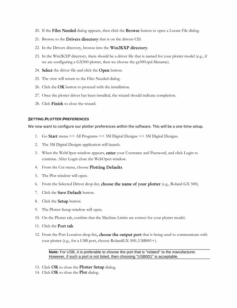
20. If the Files Needed dialog appears, then click the Browse button to open a Locate File dialog.
21. Browse to the Drivers directory that is on the drivers CD.
22. In the Drivers directory, browse into the Win2KXP directory.
23. In the Win2KXP directory, there should be a driver file that is named for your plotter model (e.g., if we are configuring a GX500 plotter, then we choose the gx500.rpd filename).
24. Select the driver file and click the Open button.
25. The view will return to the Files Needed dialog.
26. Click the OK button to proceed with the installation.
27. Once the plotter driver has been installed, the wizard should indicate completion.
28. Click Finish to close the wizard.
SETTING PLOTTER PREFERENCES We now want to configure our plotter preferences within the software. This will be a one‐time setup.
1. Go Start menu >> All Programs >> 3M Digital Designs >> 3M Digital Designs.
2. The 3M Digital Designs application will launch.
3. When the WebOpen window appears, enter your Username and Password, and click Login to continue. After Login close the WebOpen window.
4. From the Cut menu, choose Plotting Defaults.
5. The Plot window will open.
6. From the Selected Driver drop-list, choose the name of your plotter (e.g., Roland GX 500).
7. Click the Save Default button.
8. Click the Setup button.
9. The Plotter Setup window will open.
10. On the Plotter tab, confirm that the Machine Limits are correct for your plotter model.
11. Click the Port tab.
12. From the Port Location drop-list, choose the output port that is being used to communicate with your plotter (e.g., for a USB port, choose RolandGX-500_USB001+).
Note: For USB, it is preferable to choose the port that is "related" to the manufacturer. However, if such a port is not listed, then choosing "USB001" is acceptable.
13. Click OK to close the Plotter Setup dialog. 14. Click OK to close the Plot dialog.

Viewing and Selecting Patterns
FINDING AND SELECTING A PATTERN 3M Digital Designs patterns are available as a complete set of pieces that belong to a given vehicle model. The patterns that are provided with 3M Digital Designs are tested to ensure they will fit the given area of the vehicle body.
1. In 3M Digital Designs, go to the File menu and choose Open.
2. The WebOpen window for 3M Digital Designs will open, which provides options for quickly locating the patterns for your given vehicle model.
3. From the Select Year drop-list, choose the year in which the vehicle was released.
4. From the Select Make drop-list, choose the car manufacturer.
5. From the Select Model drop-list, choose the car model. Per your selections, the dialog will list the available patterns.
6. For a given vehicle, move the cursor over the vehicle name to view its Trim Description, which provides details that you can use to confirm that the given body package is what you need.
Generally, the Trim Description allows you to differentiate between the slight variations that car manufacturers will introduce to a given model line. Compare the Trim Description with the actual vehicle that you are working with, so as to confirm that you are using the correct pattern.
• For example, if the Trim Description states “2 DOOR,” then the pattern will be for a model that has two doors.
• For example, if the Trim Description states “WITH FRONT UNDER SPOILER,” then the pattern will be for a model that has a spoiler under the front bumper.
• For example, if the Trim Description states “4 DOOR,” then the pattern will be for a model that has four doors.

7. To preview the kits available for the trim model you are interested in, move your cursor to the Preview button and click to open a face sheet displaying an illustration of all available pieces.
8. To go back to the home page to being looking for a new year, make and model move your cursor over the Browse button and click.
9. For the pattern that you want, click the Download link. 10. The pattern should now appear on the 3M Digital Designs workspace.
Note how the pieces within the pattern are grouped in order to minimize wasted material when cutting (i.e., film).
To get back to the pattern selection page move your cursor over the File icon on the left hand side of the workspace and click.

Cutting Patterns into Kits CUTTING A PATTERN * These instructions use Roland® brand plotters to illustrate how to cut a Digital Designs pattern. If you use a different brand of plotter follow that manufacturers recommended procedures for setting film into your cutting machine.
1. The pattern should now appear on the 3M Digital Designs workspace.

Note how the pieces within the pattern are grouped in order to minimize wasted material when cutting (i.e., film).
2. With the mouse, drag a marquee box to select the pieces that you wish to cut. 3. A bounding box will indicate the corners and sides of your selection. 4. At the far-left of the workspace is the Tools toolbar. 5. On the Tools toolbar, locate the Cut Tool, which has the appearance of a pair of scissors. 6. Click the Cut Tool.

7. Your selected pieces will now be previewed in a Cut Preview mode. 8. Cut settings will appear along in the SmartBar along the top of the workspace. 9. A floating Cut Toolbox will also appear.
LOADING FILM INTO THE PLOTTER * These instructions use Roland® brand plotters to illustrate how to cut a Digital Designs pattern. If you use a different brand of plotter follow that manufacturers recommended procedures for setting up film into your cutting machine. At this point, our cut job is shown in Cut Preview mode. We now want to confirm that we have loaded a roll of the appropriate dimensions.
1. In the SmartBar, confirm the Length (Horizontal Size) and the Width (Vertical Size) values that are listed.
• The top field indicates the length of film that will be fed through the plotter. • The bottom field indicates how “tall” or “wide” the piece is. Use this value as a guide for
choosing the roll width that is loaded into the plotter.
2. Before proceeding, walk over to your plotter and load the film. 3. When loading new film into the plotter, always check that the width is sufficient, and that the roll
length will accommodate the job.

4. Behind the plotter are two bars. Place the roll of film ON TOP of these bars.
5. Behind the plotter are levers that are used to raise and lower the pinch rollers when loading media.
6. Raise the pinch rollers, and then feed the film under the pinch rollers. 7. Position the pinch rollers, such that they line up with the feed grips that are beneath the film.
Above the pinch rollers, notice that the gray bars indicate where the feed grips beneath the film.

8. Positioned the pinch rollers close to the edges of the film, so you can have the maximum amount of media available for cutting.
9. Behind the plotter, use the levers to lower the pinch rollers, such that the film is ready for cutting.
THE PLOTTER CONTROL PANEL Once the film has been loaded, we want the plotter to measure the film width, which we will check versus the width of our pattern.

3. Now that the pinch rollers have been lowered into place, the status screen will query whether you have loaded a roll or sheet of film.
4. As can be seen on the status screen, “roll” is the default selection. 5. On the control panel, press the [Enter] button to confirm the “roll” selection. 6. At this point, the plotter head will move the full length of the machine and measure the width of the
film. 7. The control panel will indicate the width of the film. 8. Back in the 3M Digital Designs application, confirm that the pattern width will fit the measured
width of the film.

CONFIRMING THE AVAILABLE LENGTH OF MEDIA
1. In the 3M Digital Designs application, make note of the film length that is required to complete the job.
2. On the plotter control panel, press the [DOWN] button to feed the film, until you can confirm that there is enough film.
The control panel will display the amount of film that is being fed.
3. Once you have confirmed that there is enough film, press the [UP] button to feed the film back to the starting position.
Note: When feeding the media, it is critical that the media is feeding straight (i.e., it is not skewed at an angle). Otherwise, there is a risk that the pattern may be cut askew and will not meet the exact shape required to fit the vehicle.
CONFIRMING THAT THE MEDIA IS ALIGNED
1. Beneath the film and plotter head are graduations that are used to observe film alignment. 2. When the film is at the home position, make note of where the film edge is with respect to the
graduations. 3. On the control panel, press the down button to feed the film. 4. If the film is aligned, then the edge should remain consistently along the same position as at the
home position (i.e., the edge does not drift).
Slight movement of perhaps 1/32” is acceptable. Otherwise, it is necessary to release the pinch rollers and realign the film.
CUTTING THE FILM Back in 3M Digital Designs, we are now ready to output the cut job. The job should still be in Cut Preview mode, and the Cut Toolbox should be floating over the workspace.

1. At the far-right of the Cut Toolbox, click the Cut button. 2. The cut data will now be sent to your plotter, and the film will feed back and forth, whilst the plotter
head scores the media.
If we had not taken care to align the film on the plotter, then bad cuts would likely occur at this stage.
3. When the cutting is complete, the plotter head will move to the end of the job and cut the film, thereby separating the job from the film c roll.
CUTTING THE NEXT PIECE
1. In 3M Digital Designs, click the Close button to exit Cut Preview mode. 2. Press [F7] to zoom to the remaining artwork. 3. Repeat the previous steps of selecting the job, activating cut preview, checking for available media
length on the roll, and outputting the job.

3M™ Digital Designs Contact Information
E-MAIL: [email protected]
WEBSITE: www.3M.com/autoprotection
SOFTWARE SUPPORT: 651‐733‐1000
PATTERN AND APPLICATION SUPPORT: 626‐962‐1236
626‐962‐1431
626‐962‐1939