Introduction - booksite.elsevier.com · “sucker-rod pumping.” ... A newly emerged rod-pumping...
8
CHAPTER 1 Introduction Contents 1.1 Artificial Lifting 1 1.1.1 Gas Lifting 2 1.1.2 Pumping 2 1.1.3 Comparison of Lift Methods 4 1.2 Short History of ESP Applications 5 1.3 Basic Features of ESP Installations 6 1.3.1 Applications 6 1.3.2 Advantages, Limitations 7 References 8 1.1 ARTIFICIAL LIFTING Usually, oil wells in the early stages of their lives flow naturally to the sur- face and are called “flowing wells.” Flowing production means that the pressure at the well bottom is sufficient to overcome the sum of pressure losses occurring along the flow path to the separator. When this criterion is not met, natural flow ends and the well dies. The two main reasons of a well’s dying are: • their flowing bottomhole pressure drops below the total pressure losses in the well, or • pressure losses in the well become greater than the bottomhole pres- sure needed for moving the wellstream to the surface. The first case occurs due to the removal of fluids from the underground reservoir; the second case involves an increasing flow resistance in the well. This can be caused by: • an increase in the density of the flowing fluid as a result of decreased gas production, or • various mechanical problems like a small tubing size, downhole restrictions, etc. Artificial lifting methods are used to produce fluids from wells already dead or to increase the production rate from flowing wells; and several lifting Electrical Submersible Pumps Manual ISBN 978-1-85617-557-9 # 2009 Elsevier Inc. All rights reserved. 1
-
Upload
phungnguyet -
Category
Documents
-
view
229 -
download
0
Transcript of Introduction - booksite.elsevier.com · “sucker-rod pumping.” ... A newly emerged rod-pumping...
CHAPTER11Introduction
Contents
1.1 Artificial Lifting 11.1.1 Gas Lifting 21.1.2 Pumping 21.1.3 Comparison of Lift Methods 4
1.2 Short History of ESP Applications 51.3 Basic Features of ESP Installations 6
1.3.1 Applications 61.3.2 Advantages, Limitations 7
References 8
1.1 ARTIFICIAL LIFTING
Usually, oil wells in the early stages of their lives flow naturally to the sur-
face and are called “flowing wells.” Flowing production means that the
pressure at the well bottom is sufficient to overcome the sum of pressure
losses occurring along the flow path to the separator. When this criterion
is not met, natural flow ends and the well dies. The two main reasons of
a well’s dying are:• their flowing bottomhole pressure drops below the total pressure lossesin the well, or
• pressure losses in the well become greater than the bottomhole pres-sure needed for moving the wellstream to the surface.
The first case occurs due to the removal of fluids from the underground
reservoir; the second case involves an increasing flow resistance in the well.
This can be caused by:• an increase in the density of the flowing fluid as a result of decreasedgas production, or
• various mechanical problems like a small tubing size, downholerestrictions, etc.
Artificial lifting methods are used to produce fluids from wells already dead
or to increase the production rate from flowing wells; and several lifting
Electrical Submersible Pumps Manual ISBN 978-1-85617-557-9# 2009 Elsevier Inc. All rights reserved.
1
mechanisms are available to choose from. One widely used type of artifi-
cial lift method uses a pump set below the liquid level in the well to
increase the pressure so as to overcome the pressure losses occurring along
the flow path. Other lifting methods use compressed gas, injected from the
surface into the well tubing to help lifting of well fluids to the surface.
Although all artificial lift methods can be distinguished based on the
previous basic mechanisms, the customary classification is somewhat differ-
ent as discussed below.
1.1.1 Gas LiftingAll versions of gas lift use high-pressure natural gas injected in the well-
stream at some downhole point. In continuous flow gas lift, a steady rate
of gas is injected in the well tubing aerating the liquid and thus reducing
the pressure losses occurring along the flow path. Due to the reduction
of flowing mixture density, consequently flow resistance, the well’s
original bottomhole pressure becomes sufficient to move the gas/liquid
mixture to the surface and the well starts to flow again. Therefore, contin-
uous flow gas lifting can be considered as the continuation of flowing
production.
In intermittent gas lift, gas is injected periodically into the tubing string
whenever a sufficient length of liquid has accumulated at the well bottom.
A relatively high volume of gas injected below the liquid column pushes
that column to the surface as a slug. Gas injection is then interrupted until
a new liquid slug of the proper column length builds up again. Production
of well liquids, therefore, is done by cycles. The plunger-assisted version of
intermittent gas lift uses a special free plunger traveling in the well tubing
to separate the upward-moving liquid slug from the gas below it. These
versions of gas lift physically displace the accumulated liquids from the
well, a mechanism totally different from that of continuous flow gas lifting.
1.1.2 PumpingPumping involves the use of a downhole pump to increase the pressure in
the well to overcome the sum of flowing pressure losses. It can be further
classified using several different criteria—for example, the operational
principle of the pump used. However, the generally accepted classification
is based on the way the downhole pump is driven and distinguishes
between rod and rodless pumping.
Rod pumping methods utilize a string of rods connecting the downhole
pump to the surface driving mechanism which, depending on the type of
2 Gabor Takacs
pump used, makes an oscillating or rotating movement. The first kinds of
pumps to be applied in water and oil wells were of the positive-displacement
type requiring an alternating vertical movement to operate. The dominant
and oldest type of rod pumping is walking-beam pumping, or simply called
“sucker-rod pumping.” It uses a positive-displacement plunger pump, and
its most well-known surface feature is a pivoted walking beam.
The need for producing deeper and deeper wells with increased liquid
volumes necessitated the evolution of long stroke sucker-rod pumping.
Several different units were developed with the common features of using
the same pumps and rod strings as in the case of beam-type units, but with
substantially longer pump stroke lengths. The desired long strokes did not
permit the use of a walking beam, and completely different surface driving
mechanisms had to be invented. The basic types in this class are distin-
guished according to the type of surface drive used: pneumatic drive,
hydraulic drive, or mechanical drive long-stroke pumping.
A newly emerged rod-pumping system uses a progressing cavity pump
that requires the rod string to be rotated for its operation. This pump,
like the plunger pumps used in other types of rod pumping systems, also
works on the principle of positive displacement, but does not contain any
valves.
Rodless pumping methods, as the name implies, do not have a rod
string to operate the downhole pump from the surface. Accordingly, other
means (besides mechanical) are used to drive the downhole pump, such as
electric or hydraulic. A variety of pump types are utilized with rodless
pumping including centrifugal, positive displacement, or hydraulic pumps.
Electric submersible pumping (ESP) utilizes a submerged electrical motor
driving a multistage centrifugal pump. Power is supplied to the motor
by an electric cable run from the surface. Such units are ideally suited to
produce high liquid volumes.
The other lifting systems in the rodless category all employ a high-
pressure power fluid that is pumped down the hole. Hydraulic pumping
was the first method developed; such units have a positive-displacement
pump driven by a hydraulic engine, contained in one downhole unit.
The engine or motor provides an alternating movement necessary to oper-
ate the pump section. The hydraulic turbine-driven pumping unit consists
of a multistage turbine and a multistage centrifugal pump section
connected in series. The turbine is supplied with power fluid from the sur-
face and drives the centrifugal pump at high rotational speeds, which lifts
well fluids to the surface.
3Introduction
Jet pumping, although it is a hydraulically driven method of fluid lifting,
completely differs from the rodless pumping principles discussed so far. Its
downhole equipment converts the energy of a high velocity jet stream into
useful work to lift well fluids. The downhole unit of a jet pump installation
is the only oil well pumping equipment known today containing no
moving parts.
1.1.3 Comparison of Lift MethodsAlthough there are some other types of artificial lift known, their importance is
negligible compared to those just mentioned. Thus, there is a multitude of
choices available to an engineer when selecting the type of lift to be used.
Although the use of many of those lifting mechanisms may be restricted or
even ruled out by actual field conditions such as well depth, production rates
desired, fluid properties, and so on, usually more than one lift system turns
out to be technically feasible. It is then the production engineer’s responsibility
to select the type of lift that provides the most profitable way of producing the
desired liquid volume from the given well(s). After a decision is made
concerning the lifting method to be applied, a complete design of the installa-
tion for initial and future conditions should follow.
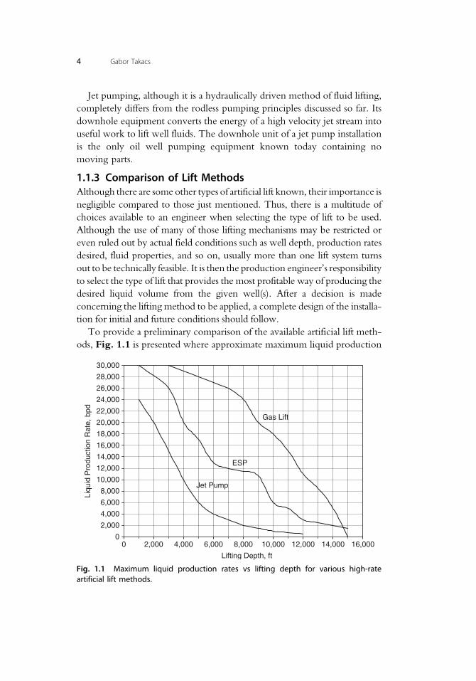
To provide a preliminary comparison of the available artificial lift meth-
ods, Fig. 1.1 is presented where approximate maximum liquid production
0
2,000
4,000
6,000
8,000
10,000
12,000
14,000
16,000
18,000
20,000
22,000
24,000
26,000
28,000
30,000
0 2,000 4,000 6,000 8,000 10,000 12,000 14,000 16,000
Lifting Depth, ft
Liqu
id P
rodu
ctio
n R
ate,
bpd
Gas Lift
Jet Pump
ESP
Fig. 1.1 Maximum liquid production rates vs lifting depth for various high-rateartificial lift methods.
4 Gabor Takacs
rates of the different installations are given [1] in the function of lifting
depth. The figure shows three lifting mechanisms capable of producing
exceptionally high liquid rates: gas lifting, ESP (electrical submersible
pumping) and jet pumping. As seen, gas lifting (continuous flow) can pro-
duce the greatest amounts of liquid from any depth. In all cases, lifting
depth has a profound importance on the liquid volume lifted with well
rates rapidly decreasing in deeper wells.
1.2 SHORT HISTORY OF ESP APPLICATIONS
Unlike most of the other artificial lift methods such as gas lifting or sucker-
rod pumping, whose invention cannot be attributed to any person or
any definite time, electrical submersible pumping was invented and devel-
oped by a Russian named Armais Arutunoff in the late 1910s [2].
In 1911, Arutunoff started the company Russian Electrical Dynamo
of Arutunoff (its acronym REDA still being known all over the world)
and developed the first electric motor that could be operated submersed
in an oil well. To acquire funding for the development of his ideas, Aru-
tunoff first emigrated to Germany in 1919, and then finally settled in the
USA in 1923. The US Patent he received on the electrical submersible
pump [3] was issued in 1926 and covered the principal features of this
new artificial lift method. The first ESP installation was successfully
operated in the El Dorado field in Kansas in 1926. Arutunoff moved to
Bartlesville, Oklahoma, in 1928 where he started the Bart Manufacturing
Co., later reorganized as REDA Pump Co. in 1930.
The first ESP units were driven by three-phase two-pole electric induc-
tion motors of 53 8= in or 71 4= in OD. The biggest motor was about 20 ft
long and developed 105 HP. Directly above the motor a seal unit was
attached whose main task was to prevent the leakage of well fluids into
the motor. On top of the seal unit, a multistage centrifugal pump lifted
well fluids to the surface. The complete ESP unit (motor, seal and pump)
was run into the well on the bottom of the tubing string, electricity being
supplied from the surface to the motor by a special three-conductor cable.
Even today, these are the main components of electrical submersible
pumping installations. After more than 80 years of operation, the company
established by Arutunoff, who alone received 90 patents related to sub-
mersible equipment, is still one of the leading suppliers of ESP equipment
to the world’s petroleum industry.
5Introduction
From its conception, ESP units have excelled in lifting much greater
liquid rates than most of the other types of artificial lift and found their best
use in high rate on- and offshore applications. It is believed that today
approximately 10% of the world’s oil supply is produced with submersible
pumping installations.
During its long history, ESP equipment underwent a continuous
improvement. The first breakthrough came in the early 1950s when seal
units (a.k.a. protectors) with mechanical seals on their shafts considerably
increased ESP run lives because they provided a much better protection
against leakage of well fluids into the motor. Production of gassy wells
was always a problem and the use of simple gravitational (reverse-flow)
gas separators did not solve the problem completely until the first rotary
gas separator [4] was introduced in the early 1970s. Although the other
components of the ESP unit have also evolved, the next revolutionary
moment came when the first variable speed ESP unit was installed in
August 1977 [5]. The variable speed drive (VSD) changes the frequency
of the electric current driving the ESP motor and thus considerably modi-
fies the head performance of the submersible pump. By properly setting
the driving frequency, a very basic limitation of ESP units can be elimi-
nated and the lifting capacity of the submersible pump can easily be mod-
ified to match the inflow performance of the well. Without a VSD unit, in
wells with unknown liquid production capacities the ESP unit has to be
exchanged with a unit better fitting the inflow to the well, which usually
involves a costly workover operation.
Running and pulling of conventional ESP units involves the use of heavy
workover units because the tubing string has to be moved into or out of the
well. Reduction of the high workover costs can be accomplished if the ESP
unit is run on a wire rope of the right mechanical strength. Cable suspended
units, first appearing in the oil field in the late 1970s, became very popular
for their advantageous features, especially in the offshore environment [6].
Similar advantages can be reached with coiled tubing (CT) conveyed ESP
units, first installed in Alaskan fields in 1992 [7].
1.3 BASIC FEATURES OF ESP INSTALLATIONS
1.3.1 ApplicationsThe first big-scale success for ESP installations occurred in the late 1920s
when the Oklahoma City field was converted from beam pumping to sub-
mersible pumping. The ESP units could lift oil volumes of up to 1,000
6 Gabor Takacs
bpd, an amount 2–3 times greater than beam pumping units were able to
produce [2]. Early applications also showed their advantages in waterflood
operations where increasing the liquid rates could greatly raise oil
production.
Today, main applications include onshore waterflood operations (both
liquid production and water injection), offshore production, and all other
cases where electricity is available and large volumes have to be lifted. The
usual range of liquid rates, in the typical installation depth range of 1,000
to 10,000 ft, is between 20,000 and 200 bpd, heavily decreasing with well
depth, see Fig. 1.1. Extreme depth and liquid rate limits of present-day
ESP units are around 15,000 ft and 30,000 bpd, respectively. One recent
case study [8] reported a sustained liquid rate of 31,800 bpd from installa-
tions utilizing 2,000 HP tandem motors in wells with 51 2= in tubing and
95 8= in casing strings.
Special applications outside the petroleum industry, like production
from water supply wells, can reach much greater liquid rates; one major
manufacturer offers submersible pumps capable of 64,000 bpd maximum
production rate.
1.3.2 Advantages, LimitationsGeneral advantages of using ESP units can be summed up as follows, based
on [9–11]:• Ideally suited to produce high to extremely high liquid volumes frommedium depths. Maximum rate is around 30,000 bpd from 1,000 ft.
• Energy efficiency is relatively high (around 50%) for systems produc-ing over 1,000 bpd.
• Can be used in deviated wells without any problems.• Requires low maintenance, provided the installation is properlydesigned and operated.
• Can be used in urban locations since surface equipment requiresminimal space.
• Well suited to the offshore environment because of the low spacerequirements.
• Corrosion and scale treatments are relatively easy to perform.
General disadvantages are listed below:• A reliable source of electric power of relatively high voltage must beavailable.
• The flexibility of ESP systems running on a constant electrical fre-quency is very low because the centrifugal pump’s liquid producingcapacity practically cannot be changed. Proper installation design basedon accurate well inflow data and matching the unit’s capacity to well
7Introduction
deliverability is crucial, otherwise costly workover operations arerequired to run a new unit in the well. The use of variable speeddrives can eliminate most of these problems but at an extra cost.
• Free gas present at suction conditions deteriorates the submersiblepump’s efficiency and can even totally prevent liquid production.The use of gas separators or gas handlers is required if more than 5%of free gas enters the pump.
• Sand or abrasive materials in well fluids increase equipment wear.Special abrasion-resistant materials are available but increase capitalcosts.
• Repair of ESP equipment in oilfield conditions is difficult, faultyequipment must be sent to the manufacturer’s repair shop.
• High well temperature is a limiting factor, standard equipment islimited to about 250�F, and use of special materials increases the tem-perature limit to 400�F.
• Production of high viscosity oils increases power requirements andreduces lift.
• Running and pulling costs are high because of the need for heavyworkover rigs. Cable suspended or CT (coiled tubing) deployed ESPunits reduce workover costs.
References
1. Artificial Lift Systems Brochure. Weatherford Co., Houston, Texas, 1999.2. History of Petroleum Engineering. American Petroleum Institute, Dallas, Texas, 1961.3. Arutunoff, A.: “Electrically Driven Pump.” US Patent 1,610,726, 1926.4. Bunnelle, P. R.: “Liquid-Gas Separator Unit.” US Patent 3,887,342, 1975.5. Divine, D. L.: “A Variable Speed Submersible Pumping System.” Paper SPE 8241
presented at the 54th Annual Fall Technical Conference and Exhibition held in LasVegas, September 23–26, 1979.
6. Taylor, D. F.: “Cable Suspended Submersible Pumps and their Related Operationaland Safety Systems.” Paper SPE 7811 presented at the Production Operations Sym-posium held in Oklahoma City, February 25–27, 1979.
7. Stephens, R. K., Loveland, K. R., Whitlow, R. R. and Melvan, J. J.: “Lessons Learnedon Coiled Tubing Completions.” Paper SPE 35590 presented at Western RegionalMeeting held in Anchorage, May 22–24, 1996.
8. Pettigrew, D. and Ling, D.: “Production Performance Evaluation of 2000 HorsepowerOilwell ESP System for 30,000 BFPD Production Capability.” Paper presented at theESP Workshop held in Houston, Texas, April 28–30, 2004.
9. Clegg, J. D., Bucaram, S. M. and Hein, N. M., Jr.: “Recommendations andComparisons for Selecting Artificial-Lift Methods.” JPT, December 1993, 1128–67.
10. Neely, B.: “Selection of Artificial Lift Methods.” Paper SPE 10337 presented at the56th Annual Fall Technical Conference and Exhibition held in San Antonio, Texas,October 5–7, 1981.
11. Brown, K. E.: The Technology of Artificial Lift Methods. Vol. 2b. PennWell Books, Tulsa,Oklahoma, 1980.
8 Gabor Takacs