Introduction of Transmission Line Pulse (TLP) Testing for ESD Analysis - Device Level

Version 2015.04.17
Wei Huang, Jerry Tichenor
Web: www.esdemc.com Email: [email protected] Tel: (+1) 573-202-6411 Fax: (+1) 877-641-9358
Address: 4000 Enterprise Drive, Suite 103, Rolla, MO, 65401
Introduction of Transmission Line Pulse (TLP) Testing
for ESD Analysis - Device Level

AG
END
AWhat is ESD?
Why do we care about ESD?
How can we protect against ESD?
How do we test for ESD robustness?
What is TLP testing?
ESD robustness tests vs. TLP testing (Pulse Shape Parameters)
Benefits of TLP testing vs. other ESD tests
Testing Procedure
Purchasing Considerations
TLP Standard Requirements
TLP Systems Comparison
TLP FAQ
References
2

WH
AT
ISESD
?
What is ESD ?
• Electrostatic Discharge (ESD) is an exchange of charge between two objects, It occurs when contact is established or if the dielectric breakdown of the material between the two objects is exceeded
3
Note: The voltages are relatively high, some of them may occur under some extreme cases.

WH
YD
OW
EC
AR
EA
BO
UT
ESD?
Why do we care about ESD?
• Potential damage to circuit designs, leading to:
• Poor product quality
• Angry customers
• Increased costs for repair and rework
• Components permanent damage by breakdown, or oxide punch through, excessive local heating as components may not be able to dissipate the energy fast enough
4
Source: 2005 ESD/EOS Symposium paper

WH
YD
OW
EC
AR
EA
BO
UT
ESD?
Hard failure - IC Damages from ESD
5
Picture 5
RS-232 interface IC after an ESD strike of 15kV

WH
YD
OW
EC
AR
EA
BO
UT
ESD?
Physical Damage, Still Functional - IC Damages from ESD
6
ESD overvoltage surge. Still operable but close to total failure.
Picture 6

WH
YD
OW
EC
AR
EA
BO
UT
ESD?
Hard failure - IC Damages from ESD
7
Picture 7
EOS (Electrostatic Over Stress)Damage

HO
WC
AN
WE
PR
OTEC
TA
GA
INST
ESD?
How can we protect against ESD?
1. Controlled Environment 1
• Reduce the potential for charge build up
• Grounded equipment and furniture
• Clean Room - Controlled humidity and particles
• Does not help when system is shipped to End-User, such as Consumer Electronics.
Picture 8 ESD Friendly Workspace
8

HO
WC
AN
WE
PR
OTEC
TA
GA
INST
ESD? C
ON
T’D
How can we protect against ESD? Cont’d
2. Improve System ESD Robustness
• Understand system working environment and potential ESD risks
• Design your system with careful ESD protection strategy ! (Please refer to System Level ESD - White Paper 1,2,3 - Industry Council on ESD Target Levels,
http://esda.org/IndustryCouncil.html)
• Understand ESD sensitivities of critical components
• Test and choose best ESD protection solutions for weakness
• Test and further improve system level ESD robustness
Design engineers need critical data from different types of ESD tests.
TLP test is a very powerful tool that provides many important data for ESD design !
Graph 1 Graph 2 9

HO
WD
OW
ETEST
FOR
ESD R
OB
USTN
ESS?
How do we test for ESD robustness?
• Human Body Model (HBM) 2
• Charged human body contact with device under test (DUT)
• ANSI/ANSI/ESDA/JEDEC JS-001-2010
• Test to 4000V, < 3A into a short (8000V optional)
• Discharge from the skin (IEC 61000-4-2 is a discharge from a metal part)
10
Rise Time (tr) for short – 2 to 10ns Decay Time (td) for short – 130 to 170ns
Picture 9

HO
WD
OW
ETEST
FOR
ESD R
OB
USTN
ESS? CO
NT’D
How do we test for ESD robustness? Cont’d
• Machine Model (MM) 3 (MM model is used very little)
• Charged machine discharge to devices, such as during production
• ESD STM5.2-2012
• Test to 400V
• < 7A into a short
11
Major Pulse Period (tpm) for short – 66 to 90ns
Graph 3

HO
WD
OW
ETEST
FOR
ESD R
OB
USTN
ESS? CO
NT’D
How do we test for ESD robustness? Cont’d
• Charged Device Model (CDM) 4
• Charged device discharge to other metal parts or ground plane, such as an integrated circuit during assembly
• ESD S5.3.1-2009
• Device is charged via a charging plate
• Non-contact discharge as grounded object approaches a charged pin
• Test to 2000V
• 30A (4pF verification module, 260ps rise time)
12
Rise Time (tr) – ~200ps, Full Width Half Height (td) - ~400ps
Graph 4
CDM Test Setup

HO
WD
OW
ETEST
FOR
ESD R
OB
USTN
ESS? CO
NT’D
How do we test for ESD robustness? Cont’d
• IEC 61000-4-2:2008 5
• Charged human body contacting a DUT with a metal, discharging to a system
• System level test
13Ideal contact discharge waveform (4kV)
Contact discharge current waveform parameters
IEC Test Configuration
EUT

HO
WD
OW
ETEST
FOR
ESD R
OB
USTN
ESS? CO
NT’D
How do we test for ESD robustness? Cont’d
• Human Metal Model (HMM) 6
• Charged human discharging through a metal tool
• ANSI/ESD SP5.6-2009
• Component level test similar to IEC 61000-4-2
• Current waveform parameters same as IEC 61000-4-2
• Can use TLP and the 50W arrangement for more reliable and automatic failure detection testing
14
50W Coaxial Source Setup
Setup A Setup B

WH
AT
ISTLP
TESTIN
G?
What is TLP Measurement ?
• Transmission-Line Pulse (TLP) Measurement is a methodology to test and study integrated circuit technologies and circuit behavior in the time domain of transient events, such as Electrostatic-Discharge (ESD), Cable Discharge Event (CDE) .
• History:
• Due to interest in Electromagnetic Pulse environments, Wunsch and Bell studied pulsed power failures in semiconductor junctions in the 1960’s. 7
• Also developed in the 1960’s, by Bradley, Higgins et.al., was the use of charged transmission lines to generate rectangular pulses 8
• In the 1980’s the idea of using Transmission Line Pulsing for modeling of ESD phenomena was introduced by Maloney and Khurana 9
• The first commercial TLP system was introduced by Barth Electronics in the mid-1990’s 10
15

TLP S
TAN
DA
RD
REQ
UIR
EMEN
TS
What is TLP Testing?
TLP Standard Requirements
• Standard TLP (STM5.5.1-2014)
• Typically 0.2 to 10 ns rise time
• 10ns to > ms pulse width (100ns typical)
• Minimum of 200MHz BW oscilloscope
• Minimum of 200MHz BW voltage probe
• Minimum of 200MHz BW current probe
• Very Fast TLP (SP5.5.2-2007)
• Typically <= 200 ps rise time
• 1 to 10ns pulse width
• Minimum of 2.5GHz BW oscilloscope with 5GSa/s sampling
• Minimum of 1GHz BW voltage probe
• Minimum of 2GHz BW current probe
16

WH
AT
ISTLP
TESTIN
G? C
ON
T’D
What is TLP Testing? Cont’d
• A basic pulse generator consists of a charge line (TL1) of length L, a switch (S1), and a High Voltage power supply (Vo)
• The length of the charge line determines the pulse width
• Standard TLP typically uses 100ns pulse width, and a 1ns rise time
• Pulses are incrementally increased until
failure, or the maximum voltage is reached
• Failure typically determined by DC leakage
current measurement
• Measurement window is typically between
the 70 to 90% region to obtain a point of
the I-V curve
17
t
I(t)
t
V(t)
IDUT
VDUT
I
V
I
V
Measurement Window
Graph 5

WH
AT
ISTLP
TESTIN
G? C
ON
T’D
What is TLP Testing? Cont’d
• I-V Characterization of TVS diode (70% to 90% window) measurement
18
Measurement Window (70 to 90% of Pulse)

WH
AT
ISTLP
TESTIN
G? C
ON
T’D
What is TLP Testing? Cont’d
• I-V Characterization of TVS diode (70% to 90% window) measurement
• 100ns Pulse
19
Semtech uClamp0541Z Datasheet ESDEMC TLP Measurement

WH
AT
ISTLP
TESTIN
G? C
ON
T’D
What is TLP Testing? Cont’d
• VF-TLP Measurement: turn on behavior of a TVS diode (first few nano-seconds of pulse)
20
RDUT vs. Time vs. Pulse Voltage Waterfall
6 VTLP Pulse
Upper RDUT value limitedfor plotting purposes
WH
AT
ISTLP
TESTIN
G? C
ON
T’D
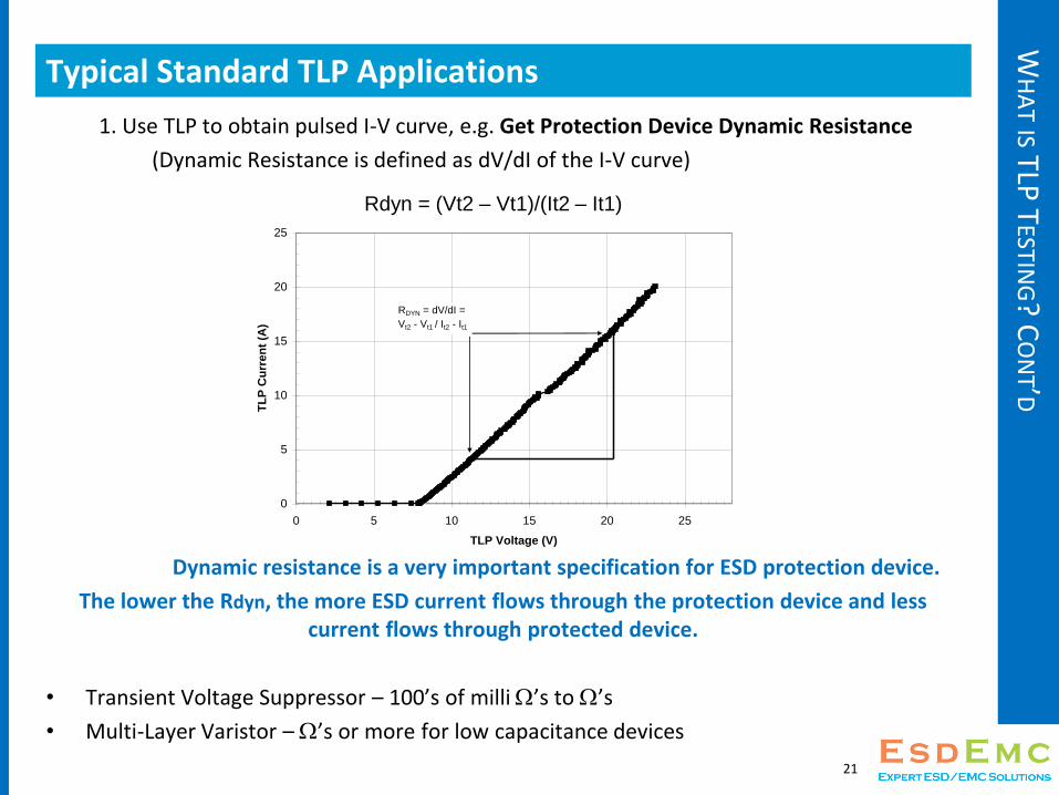
Typical Standard TLP Applications
1. Use TLP to obtain pulsed I-V curve, e.g. Get Protection Device Dynamic Resistance
(Dynamic Resistance is defined as dV/dI of the I-V curve)
Dynamic resistance is a very important specification for ESD protection device.
The lower the Rdyn, the more ESD current flows through the protection device and less current flows through protected device.
• Transient Voltage Suppressor – 100’s of milliW’s to W’s
• Multi-Layer Varistor – W’s or more for low capacitance devices
21
Rdyn = (Vt2 – Vt1)/(It2 – It1)
0
5
10
15
20
25
0 5 10 15 20 25
TLP Voltage (V)
TL
P C
urr
en
t (A
)
RDYN = dV/dI =
Vt2 - Vt1 / It2 - It1

WH
AT
ISTLP
TESTIN
G? C
ON
T’D
Typical Standard TLP Applications
2. Use TLP and auto failure check setup to test device ESD robustness / sensitivity
ESD Robustness of System / IC / Module are often evaluated with different ESD test setups. Some failure types due to transient high energy damage can be simulated with controlled rise-time / pulse-width rectangle TLP pulses or RC circuit discharging into matched 50 Ohm system waveform. TLP test results has been used to estimate HBM, IEC 61000-4-2, HMM failure level. n
Eg, ESD thermal failure correlations*(Note): TVS IEC 1 kV level = 2 A , 100 ns TLP pulse level
IC HBM 1 kV level = 1.5 A, 100 ns TLP pulse level
Please refer to publications for to TLP test correlations usage, different device has different sensitivities !
Correlation between transmission-line-pulsing I-V curve and human-body-model, Jon Barth, John Richner
ESD Relations between system level ESD and (vf-)TLP, T. Smedes, J. van Zwol, G. de Raad, T. Brodbeck, H. Wolf
A TLP-based Human Metal Model ESD-Generator for Device Qualification according to IEC 61000-4-2
Yiqun Cao 1, David Johnsson 1, Bastian Arndt 2 and Matthias Stecher
Pitfalls when correlating TLP, HBM and MM testing, Guido Notermans, Peter de Jong and Fred Kuper
A Failure Levels Study of Non-Snapback ESD Devices for Automotive Applications, Yiqun Cao , Ulrich Glaser , Stephan Frei and Matthias Stecher
Correlation Between TLP, HMM, and System-Level ESD Pulses for Cu Metallization, Y. Xi, S. Malobabic, V. Vashchenko, and J. Liou
Capacitive Coupled TLP (CC-TLP) and the Correlation with the CDM, Heinrich Wolf, Horst Gieser, Karlheinz Bock , Agha Jahanzeb, Charvaka Duvvury, Yen-Yi Lin
….. (please check for your device and applications)
Note: 1. Standard TLP doesn’t give first peak kind of pulse as IEC61000-4-2, so device failures during first peak can not repeat TLP tests. VF-TLP can provide fast rise-time and short pulse to approach the event.
2. Standard TLP are based on 50 Ohm impedance, while other ESD model are based on different impedance system so the voltage applied before device fully turn-on could be very different and cause different failure types.
22

Snapback Measurement of N-channel MOSFET
100ns TLP with <=200ps rise time, Overlap TDR measurement method was used
The snapback is due to Rdut has changed during the 100 ns pulse stressing
Typical TLP Applications 3. Test device TLP I-V curve to determine Safe Operation Area of Device
Snapback

Electrical Safe Operating Area of N-ch MOSFET
Safe operating area (SOA) is an important electrical property to understand the
ESD/EOS transient limitation of a component.

WH
AT
ISTLP
TESTIN
G? C
ON
T’D
Typical Standard TLP Applications
4. Characterize device turn-on/off transient characteristic (the 3D waterfall plots)
e.g. ESD protection device react speed
5. Characterize device Charge recovery effects
e.g. reverse and forward recovery of diodes
6. Characterize device linearity under pulsed transient
e.g. capacitance changes over high voltage
7. Characterize device break down effects
e.g. Touch panel sensor traces sparking / fuse effect during ESD
8. Characterize saturation effects on common mode chokes and Ethernet magnetics
9. Measure the non linearity of capacitance of Multi-Layer capacitors
....
• Note, there are more system level applications of TLP will be covered in another PPT release in 2015 Q2, please contact us if you needed it.
25

WH
AT
ISTLP
TESTIN
G? C
ON
T’DWhat is TLP Testing? Cont’d
• Very Fast TLP (VF-TLP)
• Commonly used for characterizing device Clamping Speed and Gate Oxide Punch Thru
• Pulse widths are very narrow (< 10ns)
• Rise times are at least 15% of Pulse Widths (100 ps to 500ps) at least? Or less than?
• A VF-TLP measurement setup (typically a low loss delay line with wide-bandwidth voltage pick-up T, or a wide-bandwidth directional coupler or a pair of wide-bandwidth direct I and V probes very closely positioned DUT, etc… ) is build so that the incident and reflected pulses can be measured separately and precisely
• De-embedding of the cable loss is necessary and performed using frequency domain techniques
26
Graph 6
A Typical VF-TLP Measurement Setup with Delay Line

ESDEM
C TEC
HN
OLO
GY
LLC
Ultra Fast VF-TLP Pulse
ESDEMC ES621 VF-TLP Waveform with 60 ps rise-time, 1ns pulse widthMeasured with 18GHz Cable/ATT + 23 GHz/100Gs Scope Tek MSO 72304DX

• Use TLP to Check ESD Protection Circuit Peak Pass Through Voltage and Clamping Voltage
• Peak voltage is the initial response to the pulse edge rate• Clamping voltage is the output voltage when protection device fully turns
on and clamps • Some sensitive device are sensitive to short time peak voltage (high E-field
strength), therefore both parameters are important to understand the device sensitivity and design best ESD protection solution.
Peak
Clamping
What is TLP Testing? Cont’d

ESD R
OB
USTN
ESSTESTS
VS. TLP
TESTING
ESD Robustness Tests vs. TLP Testing (Pulse Shape Parameters)
29
HBM MM IEC (2nd Peak) IEC (1st Peak) CDM
Typical max Peak V*
4000V 400V 8kV (contact) 2000V
Typical max Peak I*
< 3A (short) < 7A (short) 16A (@30ns) 30A 30A
Rise Time* 2 – 10ns ~ns – 10ns ~ns 800ps < 200ps
Pulse Width* 130 – 170ns 66 – 90ns ~100ns ~5ns < 400ps
Pulse shape compatible
withStandard TLP Standard TLP Standard TLP VF-TLP VF-TLP
TypicalFailure Modes
Junction damage, metal
penetration, melting of
metal layers, contact spiking,
gate-oxidedamage 11
Junction damage,
melting, gate-oxide damage
11
Melting failureOxide punch
through
Gate-oxidedamage, charge
trapping, junction
damage 11
* Typical values noted in each respective standard.

BEN
EFITSO
FTLP
TESTING
VS. O
THER
ESD TESTS
Benefits of TLP testing vs. other ESD tests
• Well Defined Consistent Waveform Shape
• Both circuit and waveform defined in ESD simulator standards are too flexible (no impedance control for test path, 30% tolerance at only certain time …) This cause ESD simulators to provide very different ESD test results between different test sites. TLP pulse is very clean and consistent.
• Highly Repeatable Test Setup
• Fatigue from holding ESD simulator with hand leads to inconsistency setup, vs TLP test with Jigs for mounting components give a more controlled test.
• Fast Automatic Test, Measurement and Report !
• Usually TLP test is done with full automation control of Pulsing, DC Leakage, I-V Curve real-time update and automatic failure detection
• Important Device Behavior is recorded for ESD analysis and design !
• Many useful parameters can be extracted from TLP tests for device transient behavior analysis, modeling and System-Efficient ESD Design (SEED). However traditional ESD tests only generate pulse for P/F results.
30

TESTIN
GP
RO
CED
UR
E
General Testing Procedure
• SOZL (Short – Open – Zener – Load) Calibration (only if change setup)
• Short and Open measurements provide Series and Shunt resistances, respectively
• Zener and Load measurements provide Voltage and Current correction factors, respectively
• This calibration should be performed every few months or if equipment is changed
• Test standard for comparison
• Measure a well known device for comparison
• Reporting
• Pulse width
• Rise time
• Failure type, and level (DC Leakage, Fusing, Snapback)
• Pulse Level, DUT Voltage, and DUT Current at failure
• Dynamic Resistance if applicable
• Snapback (eSOA)
31

PU
RC
HA
SING
CO
NSID
ERA
TION
S
TLP System Configuration Considerations
• What applications you want to test with TLP ?
• Evaluate ESD protection devices performance (Compare Rdyn and Clamping speed)
• Evaluate ESD failure level of device and module
• Different pulse shape (TLP, HMM, HBM etc…) or pulse-width, rise-time might needed, and wide range of current injection level (40A, 90A, 160A etc…)
• Evaluate Safe Operation Area
• A wide range of different pulse-width selection and injection level is needed.
• Touch panels breakdown and fuse sensitivity
• Differential Pulse injection and measurement
• What equipment will you need to configure ?
• Pulse generator – TLP / VF-TLP / HMM / HBM etc…
• Device probing method ? – PCB with SMA connector, IC test jig, probe station
• Single-end or differential Injection ? --- HV wideband splitter & Inverter
• Current and Voltage measurement method – direct probes
• Transient data capture – Oscilloscope (bandwidth depends on application)
• Bias and DC measurement -- SMU / Power Source / Picoammeter
32
TLP S
YSTEMS
CO
MP
AR
ISON
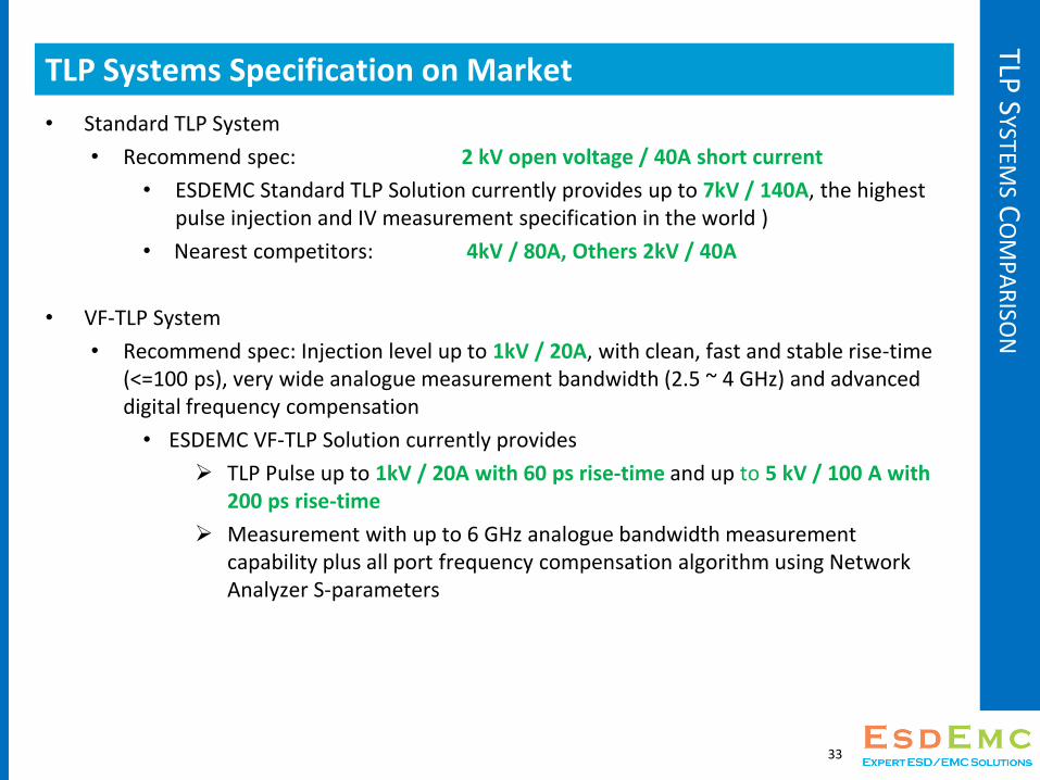
TLP Systems Specification on Market
• Standard TLP System
• Recommend spec: 2 kV open voltage / 40A short current
• ESDEMC Standard TLP Solution currently provides up to 7kV / 140A, the highest pulse injection and IV measurement specification in the world )
• Nearest competitors: 4kV / 80A, Others 2kV / 40A
• VF-TLP System
• Recommend spec: Injection level up to 1kV / 20A, with clean, fast and stable rise-time (<=100 ps), very wide analogue measurement bandwidth (2.5 ~ 4 GHz) and advanced digital frequency compensation
• ESDEMC VF-TLP Solution currently provides
TLP Pulse up to 1kV / 20A with 60 ps rise-time and up to 5 kV / 100 A with 200 ps rise-time
Measurement with up to 6 GHz analogue bandwidth measurement capability plus all port frequency compensation algorithm using Network Analyzer S-parameters
33
ESDEM
C TEC
HN
OLO
GY
LLC
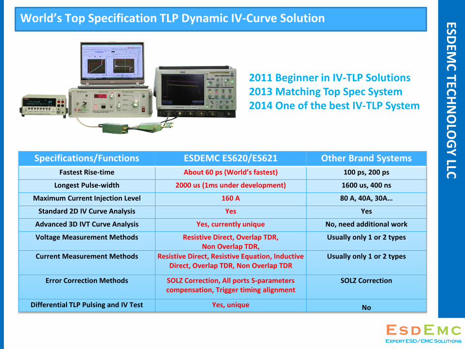
World’s Top Specification TLP Dynamic IV-Curve Solution
2011 Beginner in IV-TLP Solutions2013 Matching Top Spec System2014 One of the best IV-TLP System
Specifications/Functions ESDEMC ES620/ES621 Other Brand Systems
Fastest Rise-time About 60 ps (World’s fastest) 100 ps, 200 ps
Longest Pulse-width 2000 us (1ms under development) 1600 us, 400 ns
Maximum Current Injection Level 160 A 80 A, 40A, 30A…
Standard 2D IV Curve Analysis Yes Yes
Advanced 3D IVT Curve Analysis Yes, currently unique No, need additional work
Voltage Measurement Methods Resistive Direct, Overlap TDR, Non Overlap TDR,
Usually only 1 or 2 types
Current Measurement Methods Resistive Direct, Resistive Equation, Inductive Direct, Overlap TDR, Non Overlap TDR
Usually only 1 or 2 types
Error Correction Methods SOLZ Correction, All ports S-parameters compensation, Trigger timing alignment
SOLZ Correction
Differential TLP Pulsing and IV Test Yes, unique No

TLP S
YSTEMS
CO
MP
AR
ISON
General FAQ for TLP testing ?
• How much does TLP system cost ?
• Most TLP system in the market current cost about 80 ~ 250 K USD
• ESDEMC provides ES620 Ultra-portable and low cost version system cost about 40 – 100K from 2015 Q2 (only 1/2 of same specification system from other vendors)
• ESDEMC guarantee to provide better capability TLP system at same cost of other competitors
• Can customer use their equipment for TLP system configuration ?
• Most TLP system in the market doesn’t support wide range of instruments, but ESDEMC TLP software designed with great compatibility in mind, you can choose most equivalent instruments you had (Agilent, Tek, Lecroy, Rigol, Keithley, etc…). You change instrument settings in few clicks or contact us if you need support !
35

TLP S
YSTEMS
CO
MP
AR
ISON
General FAQ for TLP testing ?
• What bandwidth is really needed for TLP testing ?
• This really depends on the IV measurement window you want to measure, for most applications with standard 100 ns TLP, 200+ MHz bandwidth is fine if you only check the 70-90% of 100 ns pulse window for Rdyn and pulse failure level, even ESDA TLP standard require higher bandwidth.
• However if customer want to measure the device characteristic from the first ns of the pulse injection, VF-TLP generator with very clean and stable edge and 4~ 8 GHz oscilloscope is recommended.
36

TLP S
YSTEMS
CO
MP
AR
ISON
Thank you !
• Please feel free to contact [email protected] for questions about general ESD test and applications, we are expert in this field and we like to help !
• We will keep updating this ppt and we offer FREE application consulting. We also send out latest technical notes and sales promotion each quarter, please email us if you like to subscribe.
• If you are interested, below are few slides about ESDEMC Technology LLC
37

A Start-up Business Specializing in the Development of ESD/EMC Solutions and Customized HV/RF Designs from 2011, Located in Rolla, MO, USA.
ES/ESD
Solution
EMC Test
Solution
HV System
Design
RF System
Design
To be one of the best Commercial Solution Providers in the field,
by ESD/EMC Engineers, for ESD/EMC Engineers

ESDEM
C TEC
HN
OLO
GY
LLC
Development Achievements (2011.03 to present)
ESD/Transient
• World’s top spec Transmission Line Pulse System (TLP/VFTLP)
• World’s first Commercial Cable Discharge Event (CDE) System
• ESD Simulator, ESD Targets, Adapter Line
• Plus additional features…
EMC/ RF
• Microwave Material Characterization System (5-22 GHz)
• IC Strip TEM Cell (4kV/ DC-5.5 GHz)
• Wideband RF Amplifiers (Up to 40 GHz)
• Wideband Power Amplifier (4GHz/25W )
• Plus additional features…
Other Key Products
• Wideband HV Pulse Attenuator (Symmetric, 4kV / 3.5GHz)
• Oscilloscope ESD Protector (up to 6 GHz)
• HV Pulse Differential Splitter (1MHz to 2GHz)
• See website ESDEMC.COM for more products

Some Previous Customers (2011 to 2013) ESDEM
C TEC
HN
OLO
GY
LLC

Company Growth (2011 to 2013) ESDEM
C TEC
HN
OLO
GY
LLC
Niche: Solutions by ESD/EMC experts, innovative & flexible, focused on ESD/EMC design, analysis and debugging
Growth: 2010.09 Business setup in Founder’s home2011.03 to now Group of 5 professionals
ESDEMC is strategically located in the same facility with the world’s largest academia EMC research group MS&T-EMCLAB
About 40% each year

ESDEMC Group @ 2012 IEEE EMC Symposium
Oh, I have a new idea ...
We are growing … I can do
it …We can
improvise…
Fredric StevensonBusiness/Technical
Development
Wei Huang Founder/Owner
Chief Design Engineer
David PommerenkeChief Technology
Consultant
Jerry TichenorDesign Application
Engineer

REFER
ENC
ES
References1. Martin Rodgaard, 2007, ESD – Electrostatic Discharge, Retrieved Jan 13, 2015 from:
http://hibp.ecse.rpi.edu/~connor/education/Surge/Presentations/ESD_mr.pdf
2. ESDA/JEDEC Joint Standard for Electrostatic Discharge Sensitivity Testing - Human Body Model (HBM) – Component Level, ANSI/ANSI/ESDA/JEDEC JS-001-2010, April 2010.
3. ESD Association Standard Test Method for Electrostatic Discharge Sensitivity Testing - Machine Model – Component Level, ESD STM5.2-2012, July 2013.
4. ESD Association Standard for Electrostatic Discharge Sensitivity Testing - Charge Device Model (CDM) – Component Level, ESD S5.3.1-2009, December 2009.
5. International Electrotechnical Commission, Electromagnetic Compatibility (EMC) – Part 4-2: Testing and measurement techniques –Electrostatic discharge immunity test, IEC 61000-4-2:2008, 2008.
6. ESD Association Standard Practice for Electrostatic Discharge Sensitivity Testing - Human Metal Model (HMM) – Component Level, ANSI/ESD SP5.6-2009, September 2009.
7. D.C. Wunsch and R.R. Bell, “Determination of Threshold Failure Levels of Semiconductor Diodes and Transistors due to Pulse Voltages,” IEEE Trans. Nuc. Sci., NS-15, pp. 244-259, 1968.
8. D.J. Bradley, J.F. Higgins, M.H. Key and S. Majumdar, “A Simple Laser-triggered Spark Gap for Kilovolt Pulses of Accurately Variable Timing,” Opto-Electronics Letters, vol. 1, pp. 62-64, 1969.
9. T.J. Maloney and N. Khurana, “Transmission Line Pulsing Techniques for Circuit Modeling of ESD Phenomena,” 1985 EOS/ESD Symposium Conference Proceedings, pp. 49 -54, 1985.
10. W. Simburger, “AN 210 Effective ESD Protection Design at System Level Using VF-TLP Characterization Methodology,” Infineon Application Note 210, Revision 1.3, December 2012.
11. D. Byrd, T. Kugelstadt, 2011, Understanding and Comparing the Differences in ESD Testing, Retrieved Jan 14 2015 from: http://www.edn.com/design/test-and-measurement/4368466/Understanding-and-comparing-the-differences-in-ESD-testing
43

REFER
ENC
ESC
ON
T’D
References Cont’dGraph 1 & 2: (n.a.), 2013, How to Select Transient Voltage Suppressors (TVS Diode)?, Retrieved Jan 13 2015 from:
http://www.completepowerelectronics.com/tvs-diode-selection-tutorial/
Graph 3 & 4: D. Byrd, T. Kugelstadt, 2011, Understanding and Comparing the Differences in ESD Testing, Retrieved Jan 14 2015 from: http://www.edn.com/design/test-and-measurement/4368466/Understanding-and-comparing-the-differences-in-ESD-testing
Graph 5 & 6: Reference 10
Picture 1: Eric Puszczewicz, 2011, Electrostatic Discharge - ESD Basics and Protection, Retrieved Jan 13 2015 from: http://www.slideshare.net/ericpuszczewicz/esd-basics-by-transforming-technologies
Picture 2: Ron Kurtus, 2015, Static Electricity Sparks, Retrieved Jan 13 2015 from: http://www.school-for-champions.com/science/static_sparks.htm#.VLU51yvF9MY
Picture 3: K. Vermeer, 2011, Static dissipative ESD footware, Retrieved Jan 15 2015 from: http://electronics.stackexchange.com/questions/23107/static-dissipative-esd-footware
Picture 4: (n.a.), (n.d.), Anti-Static Design – ESD Protection, Retrieved Jan 15 2015 from: http://www.ecs.com.tw/ECSWebSite/Product/Product_Detail.aspx?DetailID=1446&MenuID=17&LanID=0
Picture 5: (n.a), 2000, Maxim Leads the Way in ESD Protection, Retrieved Jan 15 2015 from: http://www.maximintegrated.com/en/app-notes/index.mvp/id/639
Picture 6: T. G. Nagy, (n.d.), Effective ESD Transient Voltage Surge Suppression in New, High Speed Circuits, Retrieved Jan 15 2015 from: http://www.compliance-club.com/archive/old_archive/020930.htm
Picture 7: P. Yu, 2010, Component Failure Analysis – Hermetic Packaging, Retrieved Jan 15 2015 from: http://www.empf.org/empfasis/2010/Apr10/help-410.html
Picture 8: P. Corr, 2014, Laser Diodes: Laser diode operation 101: A user’s guide, Retrieved Jan 15 2015 from: http://www.laserfocusworld.com/articles/print/volume-50/issue-03/features/laser-diodes-laser-diode-operation-101-a-user-s-guide.html
Picture 9: S. Pefhany, 2014, FET Electrostatic Damage, Retrieved Jan 15 2015 from: http://electronics.stackexchange.com/questions/97605/fet-electrostatic-damage
44