IntroductIon - genton.com.t Microwave Antenna.pdf · Rosenberger Asia Pacific Electronic Co., Ltd....
40
MICROWAVE ANTENNAS www.RosenbergerAP.com
-
Upload
nguyennguyet -
Category
Documents
-
view
221 -
download
0
Transcript of IntroductIon - genton.com.t Microwave Antenna.pdf · Rosenberger Asia Pacific Electronic Co., Ltd....
Mic
ro
wa
ve
an
te
nn
as
Microwave antennas
Rosenberger Asia Pacific Electronic Co., Ltd.
No.3, Anxiang Street, Block B, Tianzhu Airport Industrial Zone
Beijing, China 101300
Tel : (+86 10) 80481995
Fax : (+86 10) 80497052
Email: [email protected]
Rosenberger (Shanghai) Technology Co.,Ltd.
No. 303, Xinke Road, Qingpu Industrial Zone
Shanghai, China 201707
Tel : (+86 21) 69214567
Fax : (+86 21) 69212923
Rosenberger Asia Pacific Electronic Co., Ltd. Shanghai Division
B7, No. 509, Renqing Road, East Zone of Zhangjiang High-Tech Park
Shanghai, China 201201
Tel : (+86 21) 58995997
Fax : (+86 21) 58995594
Rosenberger Asia Pacific Electronic Co., Ltd. Dongguan Division
3rd Floor, Building E, Pingqian Industrial Park, Dongkeng Town
Dongguan, Guangdong Province, China
Tel : (+86 769) 82802098
Fax : (+86 769) 82802099
Rosenberger All rights reserved. 1st Edition, 2013
Please visit our website: www.RosenbergerAP.com
www.RosenbergerAP.com

www.RosenbergerAP.com
IntroductIon
Rosenberger Hochfrequenztechnik GmbH&Co. was founded in Germany in 1958 and ranks among the leading manufacturers of high-speed interconnect solutions worldwide. To serve the continuous growth and demand of the global market, Rosenberger Asia Pacific Electronic Co., Ltd. was established in China in 1997. With its long tradition of excellence and providing creative solutions, Rosenberger Asia Pacific has excelled and earned an outstanding reputation in the Asia Pacific region.
Rosenberger Asia Pacific provides products and solutions for Telecommunication, Automotive Electronics, Information Technology, Test & Measurement, Aviation, and Medical & Industries. Their product portfolio includes:• RF In-Cabinet Connection Solutions• Total Site Solutions for Base Station Applications• In-Building Wireless Solutions and Enhancement• Microwave Transmission Systems• Passive Intermodulation Analyzers• FTTX• Data Center Cabling Systems
Rosenberger HQ, Bavaria, Germany

A
B
C
D
E
www.RosenbergerAP.com
A sales network covering the entire Asia Pacific region generates an annual turnover close to 200 million USD. Reliability and competitiveness are the cornerstones of this sustainable growth, resulting in long term partnerships with most of the leading companies in their respective industries.
Rosenberger Asia Pacific maintains 6 modern manufacturing and R&D base locations in Beijing, Shanghai, and Dongguan in China; and New Delhi in India, the largest of its kind in the Asia Pacific Region. Rosenberger Asia Pacific is an ISO 9001 quality system, ISO 14001 environmental system, and ISO/TS16949 automotive industry system certified company. Equipped with advanced machining, electronic plating, assembly and testing centers and staffed by a large group of more then 200 R&D engineers, Rosenberger Asia Pacific has developed first class production assembly lines and exercises stringent product and quality control.
Presently, Rosenberger Asia Pacific maintains a far reaching network of R&D, Production, Sales and Service which extends to the whole Asia Pacific and Middle East area. For over 50 years Rosenberger has established its brand all over the world. In the future, Rosenberger Asia Pacific will continue to provide excellent product solutions and services for its customers in the entire region.
Rosenberger Asia Pacific:
A: Beijing − Headquarters, R&D, and Production
B: Shanghai Zhangjiang − R&D and Production
C: Shanghai Qingpu − R&D and Production
D: India − R&D and Production
E: Dongguan − R&D and Production

www.RosenbergerAP.com
MISSIon StAtEMEnt
corE VAluE
• Design, manufacture and deploy total solutions for telecommunication networks worldwide• Create value for our customers through innovative products, customized services and cost
effective solutions• Maintain the highest quality standards, state-of-the-art manufacturing facilities and employ
reliable supply chain management to achieve and exceed customer expectations• Be socially responsible to our community and environment • Be committed to employee's personnel development
• Value Innovation• Customer Focus• Sustainable Growth• Social Responsibility

www.RosenbergerAP.com
ProductPortFolIoS
Base Station Antenna Feeder SystemsWireless Coverage Optimization SolutionsMicrowave Backhaul SolutionsRF In-cabinet SolutionsPassive Intermodulation Measurement SystemsFTTA/FTTH Optical Fiber SolutionsOSP Fiber Optic Outdoor Plant SolutionsIn-building Optical Network Connectivity SolutionsLow Frequency Cables and ComponentsNetwork Optimization Services
Premise Network Cabling ProductsData Center/Cloud Computing SolutionsIntelligent Infrastructure Management System
Test CablesPrecision ConnectorsCalibrationsAccessories and Tools
FAKRA Connectors and Cable AssembliesHSD® System
Non-Magnetic RF Connectors Non-Magnetic RF Cable AssembliesData/RF/Power/DC Hybrid Connectors and AssembliesCustom Data/Power Connectivity SystemFiber Optic Connectivity Products
Telecommunication System Solutions
IT/Data Communication
Testing and Measurement
Automotive
Medical & Industrial
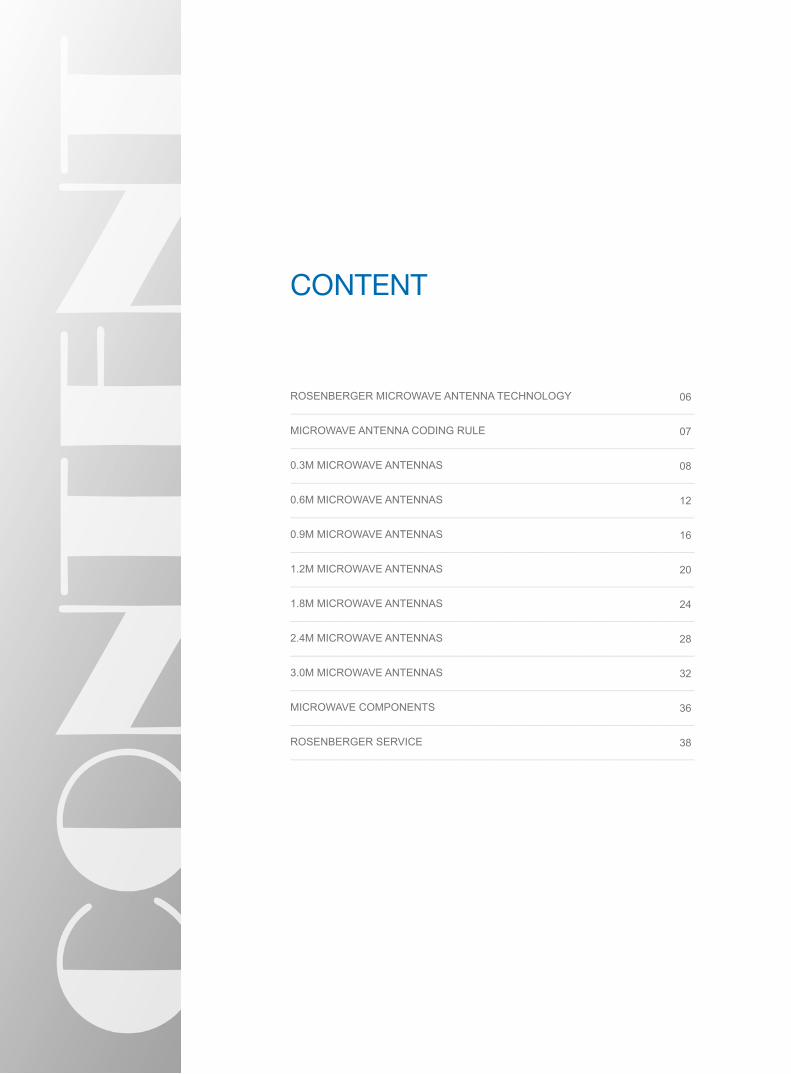
contEnt
ROSENBERGER MICROWAVE ANTENNA TECHNOLOGy ——————————————————————————————————————MICROWAVE ANTENNA CODING RULE ——————————————————————————————————————0.3M MICROWAVE ANTENNAS——————————————————————————————————————0.6M MICROWAVE ANTENNAS——————————————————————————————————————0.9M MICROWAVE ANTENNAS——————————————————————————————————————1.2M MICROWAVE ANTENNAS——————————————————————————————————————1.8M MICROWAVE ANTENNAS——————————————————————————————————————2.4M MICROWAVE ANTENNAS——————————————————————————————————————3.0M MICROWAVE ANTENNAS——————————————————————————————————————MICROWAVE COMPONENTS——————————————————————————————————————ROSENBERGER SERVICE——————————————————————————————————————
06
07
08
12
16
20 24
28
32
36
38
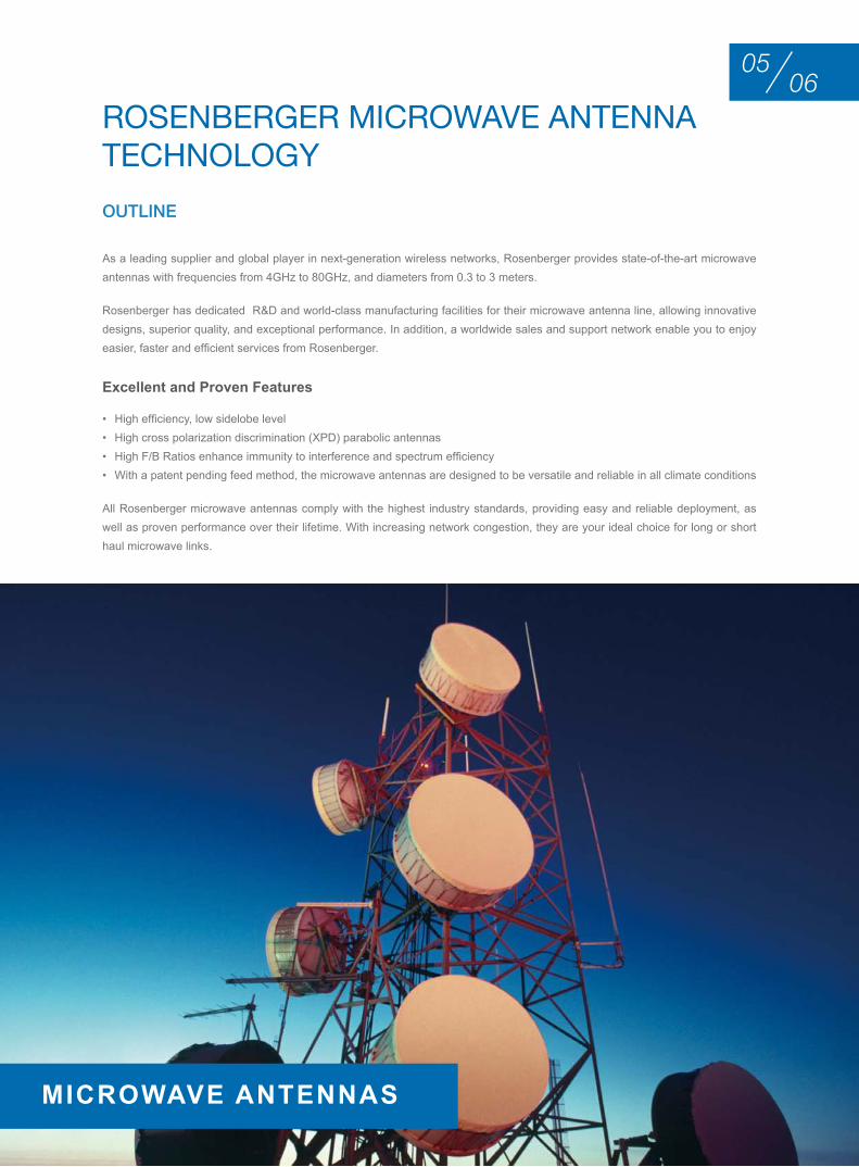
roSEnbErgEr MIcrowAVE AntEnnA tEchnology
0605
MICrowAve AnTennAS
As a leading supplier and global player in next-generation wireless networks, Rosenberger provides state-of-the-art microwave antennas with frequencies from 4GHz to 80GHz, and diameters from 0.3 to 3 meters.
Rosenberger has dedicated R&D and world-class manufacturing facilities for their microwave antenna line, allowing innovative designs, superior quality, and exceptional performance. In addition, a worldwide sales and support network enable you to enjoy easier, faster and efficient services from Rosenberger.
excellent and Proven Features
• High efficiency, low sidelobe level • High cross polarization discrimination (XPD) parabolic antennas• High F/B Ratios enhance immunity to interference and spectrum efficiency• With a patent pending feed method, the microwave antennas are designed to be versatile and reliable in all climate conditions
All Rosenberger microwave antennas comply with the highest industry standards, providing easy and reliable deployment, as well as proven performance over their lifetime. With increasing network congestion, they are your ideal choice for long or short haul microwave links.
OUTLINE
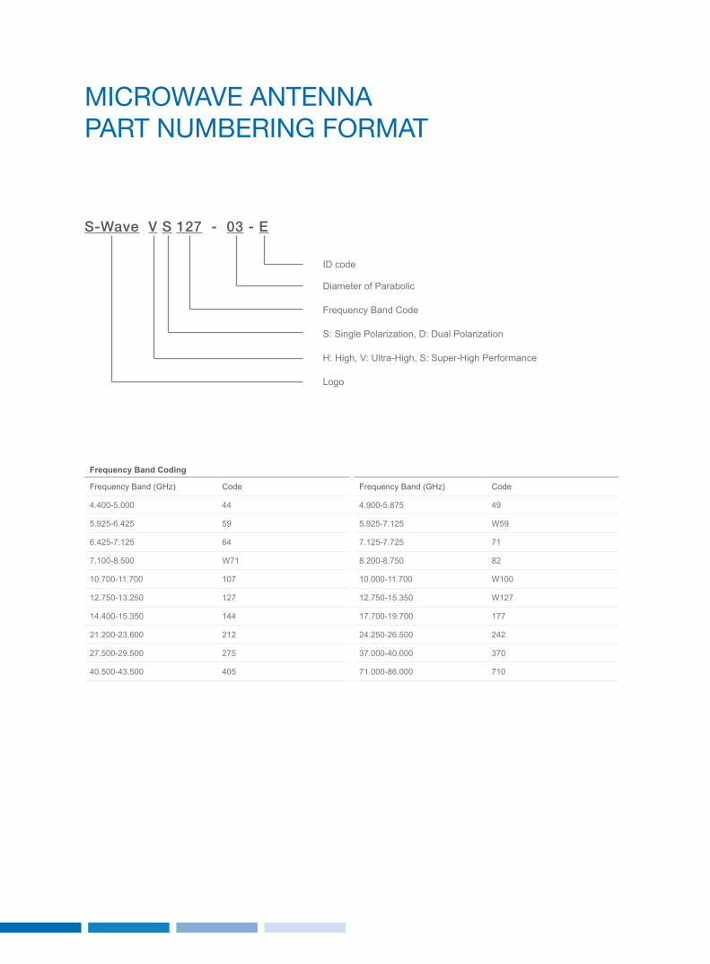
MIcrowAVE AntEnnA PArt nuMbErIng ForMAt
Logo
Diameter of Parabolic
ID code
Frequency Band Code
H: High, V: Ultra-High, S: Super-High Performance
S: Single Polarization, D: Dual Polarization
S-Wave V S 127 - 03 - E
Frequency Band Coding
Frequency Band (GHz) Code
4.400-5.000 44
5.925-6.425 59
6.425-7.125 64
7.100-8.500 W71
10.700-11.700 107
12.750-13.250 127
14.400-15.350 144
21.200-23.600 212
27.500-29.500 275
40.500-43.500 405
Frequency Band (GHz) Code
4.900-5.875 49
5.925-7.125 W59
7.125-7.725 71
8.200-8.750 82
10.000-11.700 W100
12.750-15.350 W127
17.700-19.700 177
24.250-26.500 242
37.000-40.000 370
71.000-86.000 710
0807
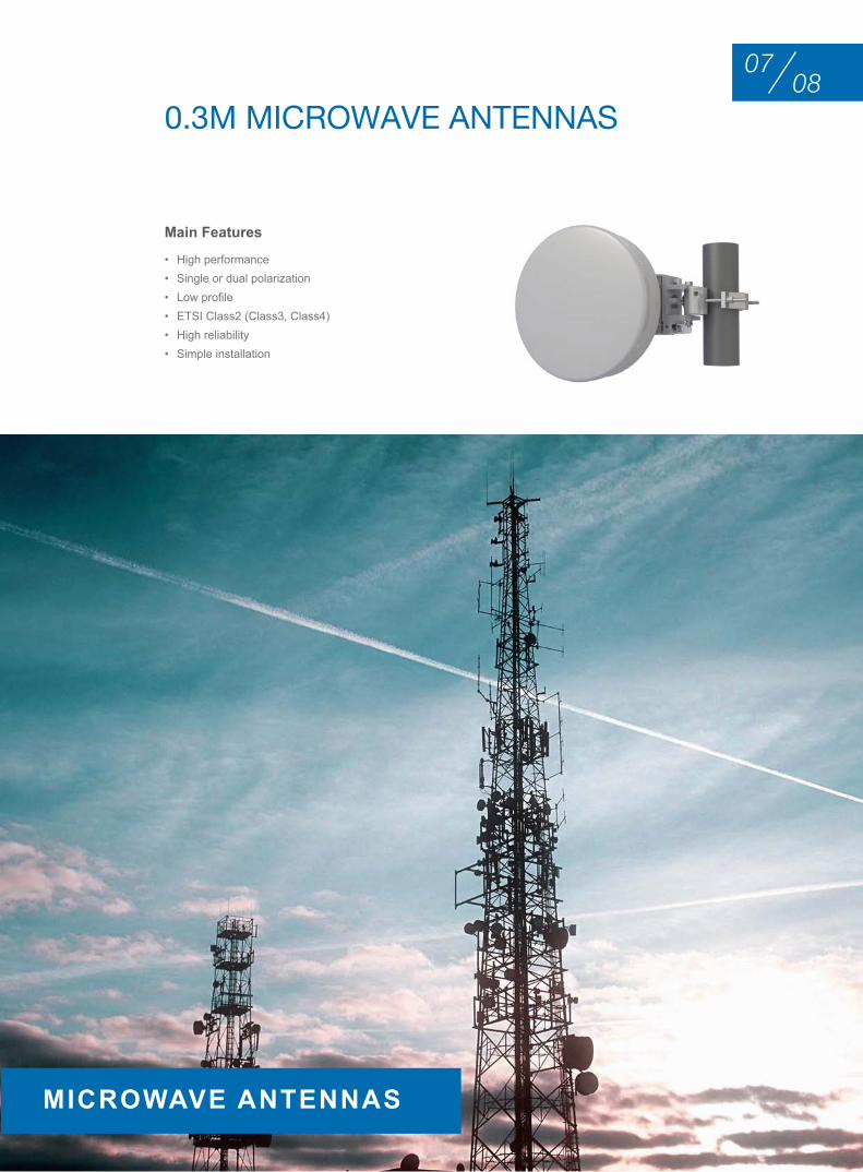
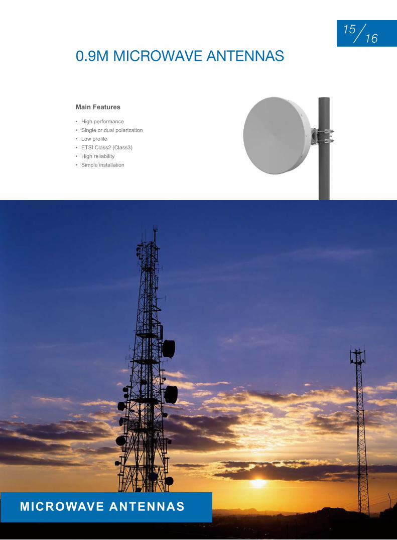
• High performance• Single or dual polarization• Low profile • ETSI Class2 (Class3, Class4)• High reliability• Simple installation
Main Features
0.3M MIcrowAVE AntEnnAS
MICrowAve AnTennAS
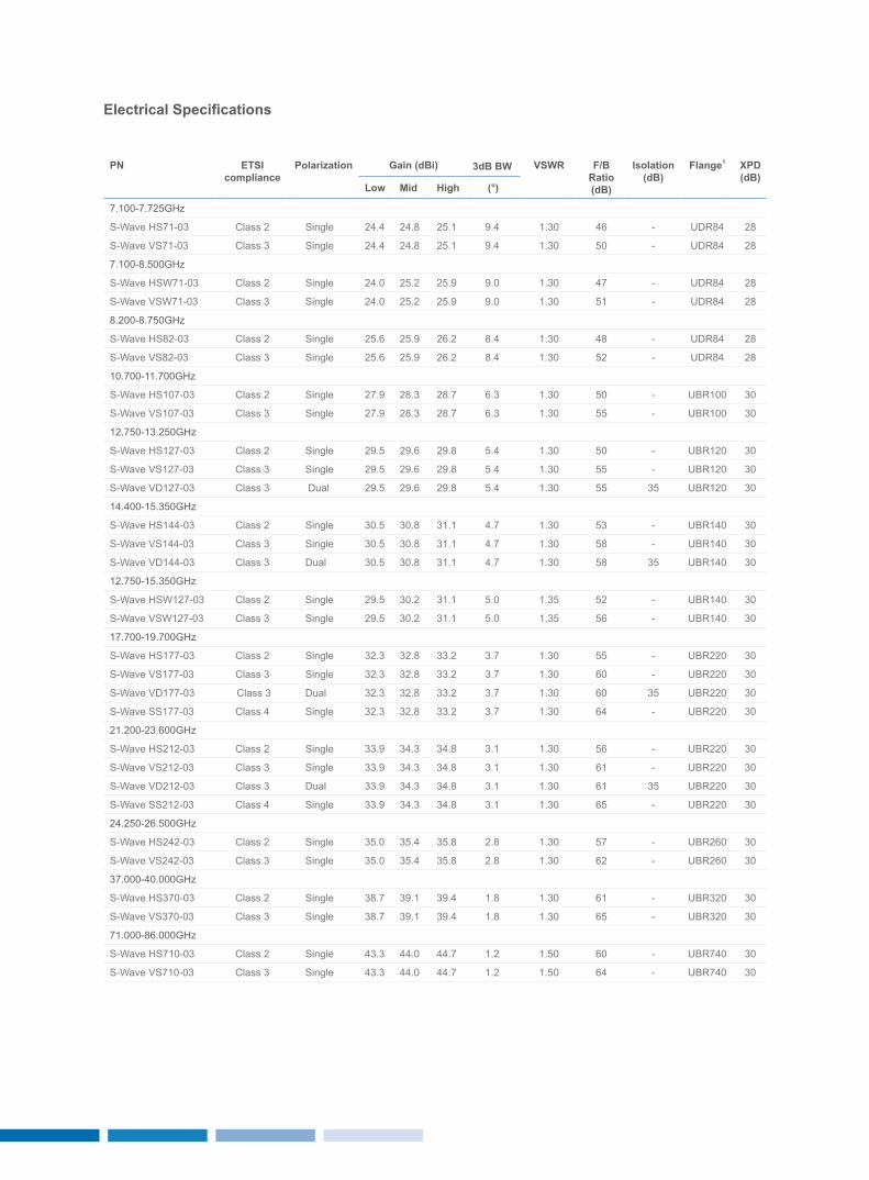
Electrical Specifications
Pn eTSI compliance
Polarization Gain (dBi) 3dB Bw vSwr F/B ratio(dB)
Isolation(dB)
Flange1 XPD(dB)
Low Mid High (°)
7.100-7.725GHz
S-Wave HS71-03 Class 2 Single 24.4 24.8 25.1 9.4 1.30 46 - UDR84 28
S-Wave VS71-03 Class 3 Single 24.4 24.8 25.1 9.4 1.30 50 - UDR84 28
7.100-8.500GHz
S-Wave HSW71-03 Class 2 Single 24.0 25.2 25.9 9.0 1.30 47 - UDR84 28
S-Wave VSW71-03 Class 3 Single 24.0 25.2 25.9 9.0 1.30 51 - UDR84 28
8.200-8.750GHz
S-Wave HS82-03 Class 2 Single 25.6 25.9 26.2 8.4 1.30 48 - UDR84 28
S-Wave VS82-03 Class 3 Single 25.6 25.9 26.2 8.4 1.30 52 - UDR84 28
10.700-11.700GHz
S-Wave HS107-03 Class 2 Single 27.9 28.3 28.7 6.3 1.30 50 - UBR100 30
S-Wave VS107-03 Class 3 Single 27.9 28.3 28.7 6.3 1.30 55 - UBR100 30
12.750-13.250GHz
S-Wave HS127-03 Class 2 Single 29.5 29.6 29.8 5.4 1.30 50 - UBR120 30
S-Wave VS127-03 Class 3 Single 29.5 29.6 29.8 5.4 1.30 55 - UBR120 30
S-Wave VD127-03 Class 3 Dual 29.5 29.6 29.8 5.4 1.30 55 35 UBR120 30
14.400-15.350GHz
S-Wave HS144-03 Class 2 Single 30.5 30.8 31.1 4.7 1.30 53 - UBR140 30
S-Wave VS144-03 Class 3 Single 30.5 30.8 31.1 4.7 1.30 58 - UBR140 30
S-Wave VD144-03 Class 3 Dual 30.5 30.8 31.1 4.7 1.30 58 35 UBR140 30
12.750-15.350GHz
S-Wave HSW127-03 Class 2 Single 29.5 30.2 31.1 5.0 1.35 52 - UBR140 30
S-Wave VSW127-03 Class 3 Single 29.5 30.2 31.1 5.0 1.35 56 - UBR140 30
17.700-19.700GHz
S-Wave HS177-03 Class 2 Single 32.3 32.8 33.2 3.7 1.30 55 - UBR220 30
S-Wave VS177-03 Class 3 Single 32.3 32.8 33.2 3.7 1.30 60 - UBR220 30
S-Wave VD177-03 Class 3 Dual 32.3 32.8 33.2 3.7 1.30 60 35 UBR220 30
S-Wave SS177-03 Class 4 Single 32.3 32.8 33.2 3.7 1.30 64 - UBR220 30
21.200-23.600GHz
S-Wave HS212-03 Class 2 Single 33.9 34.3 34.8 3.1 1.30 56 - UBR220 30
S-Wave VS212-03 Class 3 Single 33.9 34.3 34.8 3.1 1.30 61 - UBR220 30
S-Wave VD212-03 Class 3 Dual 33.9 34.3 34.8 3.1 1.30 61 35 UBR220 30
S-Wave SS212-03 Class 4 Single 33.9 34.3 34.8 3.1 1.30 65 - UBR220 30
24.250-26.500GHz
S-Wave HS242-03 Class 2 Single 35.0 35.4 35.8 2.8 1.30 57 - UBR260 30
S-Wave VS242-03 Class 3 Single 35.0 35.4 35.8 2.8 1.30 62 - UBR260 30
37.000-40.000GHz
S-Wave HS370-03 Class 2 Single 38.7 39.1 39.4 1.8 1.30 61 - UBR320 30
S-Wave VS370-03 Class 3 Single 38.7 39.1 39.4 1.8 1.30 65 - UBR320 30
71.000-86.000GHz
S-Wave HS710-03 Class 2 Single 43.3 44.0 44.7 1.2 1.50 60 - UBR740 30
S-Wave VS710-03 Class 3 Single 43.3 44.0 44.7 1.2 1.50 64 - UBR740 30
1009
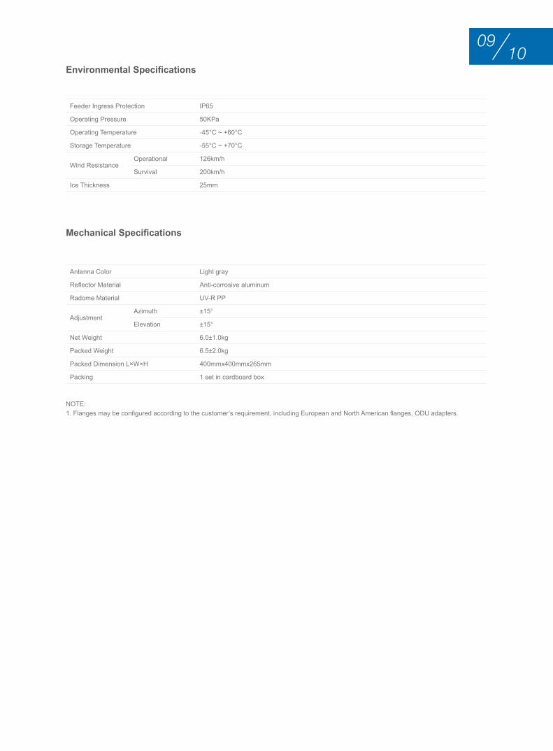
Environmental Specifications
Mechanical Specifications
Feeder Ingress Protection IP65
Operating Pressure 50KPa
Operating Temperature -45°C ~ +60°C
Storage Temperature -55°C ~ +70°C
Wind ResistanceOperational 126km/h
Survival 200km/h
Ice Thickness 25mm
Antenna Color Light gray
Reflector Material Anti-corrosive aluminum
Radome Material UV-R PP
Adjustment Azimuth ±15°
Elevation ±15°
Net Weight 6.0±1.0kg
Packed Weight 6.5±2.0kg
Packed Dimension L×W×H 400mmx400mmx265mm
Packing 1 set in cardboard box
NOTE:1. Flanges may be configured according to the customer’s requirement, including European and North American flanges, ODU adapters.
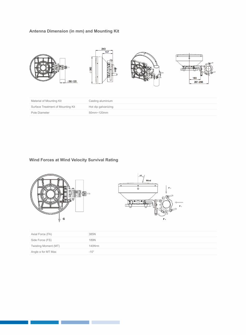
Antenna Dimension (in mm) and Mounting Kit
wind Forces at wind velocity Survival rating
Material of Mounting Kit Casting aluminium
Surface Treatment of Mounting Kit Hot dip galvanizing
Pole Diameter 50mm~120mm
Axial Force (FA) 385N
Side Force (FS) 189N
Twisting Moment (MT) 140N•m
Angle α for MT Max -10°
1211
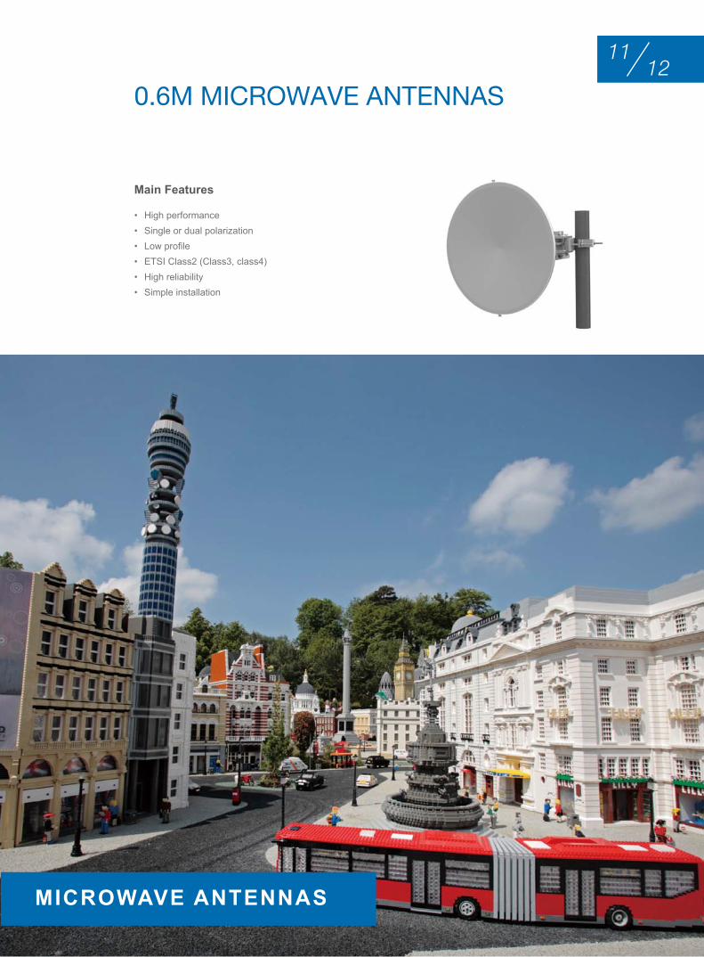
• High performance• Single or dual polarization• Low profile• ETSI Class2 (Class3, class4)• High reliability• Simple installation
Main Features
0.6M MIcrowAVE AntEnnAS
MICrowAve AnTennAS
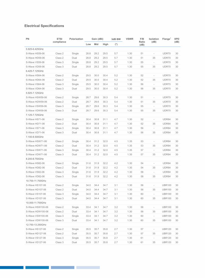
Electrical Specifications
Pn eTSI compliance
Polarization Gain (dBi) 3dB Bw vSwr F/B ratio(dB)
Isolation(dB)
Flange1 XPD(dB)
Low Mid High (°)
5.925-6.425GHz
S-Wave HS59-06 Class 2 Single 28.8 29.2 29.5 5.7 1.30 51 - UDR70 30
S-Wave HD59-06 Class 2 Dual 28.8 29.2 29.5 5.7 1.30 51 35 UDR70 30
S-Wave VS59-06 Class 3 Single 28.8 29.2 29.5 5.7 1.30 55 - UDR70 30
S-Wave VD59-06 Class 3 Dual 28.8 29.2 29.5 5.7 1.30 55 35 UDR70 30
6.425-7.125GHz
S-Wave HS64-06 Class 2 Single 29.5 30.0 30.4 5.2 1.30 52 - UDR70 30
S-Wave HD64-06 Class 2 Dual 29.5 30.0 30.4 5.2 1.30 52 35 UDR70 30
S-Wave VS64-06 Class 3 Single 29.5 30.0 30.4 5.2 1.30 56 - UDR70 30
S-Wave VD64-06 Class 3 Dual 29.5 30.0 30.4 5.2 1.30 56 35 UDR70 30
5.925-7.125GHz
S-Wave HSW59-06 Class 2 Single 28.7 29.6 30.3 5.4 1.30 51 - UDR70 30
S-Wave HDW59-06 Class 2 Dual 28.7 29.6 30.3 5.4 1.30 51 35 UDR70 30
S-Wave VSW59-06 Class 3 Single 28.7 29.6 30.3 5.4 1.30 55 - UDR70 30
S-Wave VDW59-06 Class 3 Dual 28.7 29.6 30.3 5.4 1.30 55 35 UDR70 30
7.125-7.725GHz
S-Wave HS71-06 Class 2 Single 30.4 30.8 31.1 4.7 1.30 52 - UDR84 30
S-Wave HD71-06 Class 2 Dual 30.4 30.8 31.1 4.7 1.30 52 35 UDR84 30
S-Wave VS71-06 Class 3 Single 30.4 30.8 31.1 4.7 1.30 56 - UDR84 30
S-Wave VD71-06 Class 3 Dual 30.4 30.8 31.1 4.7 1.30 56 35 UDR84 30
7.100-8.500GHz
S-Wave HSW71-06 Class 2 Single 30.4 31.2 32.0 4.5 1.35 53 - UDR84 30
S-Wave HDW71-06 Class 2 Dual 30.4 31.2 32.0 4.5 1.35 53 35 UDR84 30
S-Wave VSW71-06 Class 3 Single 30.4 31.2 32.0 4.5 1.35 57 - UDR84 30
S-Wave VDW71-06 Class 3 Dual 30.4 31.2 32.0 4.5 1.35 57 35 UDR84 30
8.200-8.750GHz
S-Wave HS82-06 Class 2 Single 31.6 31.9 32.2 4.2 1.30 54 - UDR84 30
S-Wave HD82-06 Class 2 Dual 31.6 31.9 32.2 4.2 1.30 54 35 UDR84 30
S-Wave VS82-06 Class 3 Single 31.6 31.9 32.2 4.2 1.30 58 - UDR84 30
S-Wave VD82-06 Class 3 Dual 31.6 31.9 32.2 4.2 1.30 58 35 UDR84 30
10.700-11.700GHz
S-Wave HS107-06 Class 2 Single 34.0 34.4 34.7 3.1 1.30 56 - UBR100 30
S-Wave HD107-06 Class 2 Dual 34.0 34.4 34.7 3.1 1.30 56 35 UBR100 30
S-Wave VS107-06 Class 3 Single 34.0 34.4 34.7 3.1 1.30 60 - UBR100 30
S-Wave VD107-06 Class 3 Dual 34.0 34.4 34.7 3.1 1.30 60 35 UBR100 30
10.000-11.700GHz
S-Wave HSW100-06 Class 2 Single 33.4 34.1 34.7 3.2 1.30 56 - UBR100 30
S-Wave HDW100-06 Class 2 Dual 33.4 34.1 34.7 3.2 1.30 56 35 UBR100 30
S-Wave VSW100-06 Class 3 Single 33.4 34.1 34.7 3.2 1.30 60 - UBR100 30
S-Wave VDW100-06 Class 3 Dual 33.4 34.1 34.7 3.2 1.30 60 35 UBR100 30
12.750-13.250GHz
S-Wave HS127-06 Class 2 Single 35.5 35.7 35.8 2.7 1.30 57 - UBR120 30
S-Wave HD127-06 Class 2 Dual 35.5 35.7 35.8 2.7 1.30 57 35 UBR120 30
S-Wave VS127-06 Class 3 Single 35.5 35.7 35.8 2.7 1.30 61 - UBR120 30
S-Wave VD127-06 Class 3 Dual 35.5 35.7 35.8 2.7 1.30 61 35 UBR120 30
1413
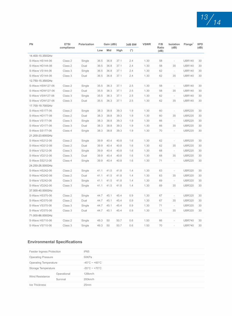
Environmental Specifications
Feeder Ingress Protection IP65
Operating Pressure 50KPa
Operating Temperature -45°C ~ +60°C
Storage Temperature -55°C ~ +70°C
Wind Resistance Operational 126km/h
Survival 200km/h
Ice Thickness 25mm
Pn eTSI compliance
Polarization Gain (dBi) 3dB Bw vSwr F/B ratio(dB)
Isolation(dB)
Flange1 XPD(dB)
Low Mid High (°)
14.400-15.350GHz
S-Wave HS144-06 Class 2 Single 36.5 36.8 37.1 2.4 1.30 58 - UBR140 30
S-Wave HD144-06 Class 2 Dual 36.5 36.8 37.1 2.4 1.30 58 35 UBR140 30
S-Wave VS144-06 Class 3 Single 36.5 36.8 37.1 2.4 1.30 62 - UBR140 30
S-Wave VD144-06 Class 3 Dual 36.5 36.8 37.1 2.4 1.30 62 35 UBR140 30
12.750-15.350GHz
S-Wave HSW127-06 Class 2 Single 35.5 36.3 37.1 2.5 1.30 58 - UBR140 30
S-Wave HDW127-06 Class 2 Dual 35.5 36.3 37.1 2.5 1.30 58 35 UBR140 30
S-Wave VSW127-06 Class 3 Single 35.5 36.3 37.1 2.5 1.30 62 - UBR140 30
S-Wave VDW127-06 Class 3 Dual 35.5 36.3 37.1 2.5 1.30 62 35 UBR140 30
17.700-19.700GHz
S-Wave HS177-06 Class 2 Single 38.3 38.8 39.3 1.9 1.30 60 - UBR220 30
S-Wave HD177-06 Class 2 Dual 38.3 38.8 39.3 1.9 1.30 60 35 UBR220 30
S-Wave VS177-06 Class 3 Single 38.3 38.8 39.3 1.9 1.30 66 - UBR220 30
S-Wave VD177-06 Class 3 Dual 38.3 38.8 39.3 1.9 1.30 66 35 UBR220 30
S-Wave SS177-06 Class 4 Single 38.3 38.8 39.3 1.9 1.30 70 - UBR220 30
21.200-23.600GHz
S-Wave HS212-06 Class 2 Single 39.9 40.4 40.8 1.6 1.30 62 - UBR220 30
S-Wave HD212-06 Class 2 Dual 39.9 40.4 40.8 1.6 1.30 62 35 UBR220 30
S-Wave VS212-06 Class 3 Single 39.9 40.4 40.8 1.6 1.30 68 - UBR220 30
S-Wave VD212-06 Class 3 Dual 39.9 40.4 40.8 1.6 1.30 68 35 UBR220 30
S-Wave SS212-06 Class 4 Single 39.9 40.4 40.8 1.6 1.30 71 - UBR220 30
24.250-26.500GHz
S-Wave HS242-06 Class 2 Single 41.1 41.5 41.8 1.4 1.30 63 - UBR320 30
S-Wave HD242-06 Class 2 Dual 41.1 41.5 41.8 1.4 1.30 63 35 UBR320 30
S-Wave VS242-06 Class 3 Single 41.1 41.5 41.8 1.4 1.30 69 - UBR320 30
S-Wave VD242-06 Class 3 Single 41.1 41.5 41.8 1.4 1.30 69 35 UBR320 30
37.000-40.000GHz
S-Wave HS370-06 Class 2 Single 44.7 45.1 45.4 0.9 1.30 67 - UBR320 30
S-Wave HD370-06 Class 2 Dual 44.7 45.1 45.4 0.9 1.30 67 35 UBR320 30
S-Wave VS370-06 Class 3 Single 44.7 45.1 45.4 0.9 1.30 71 - UBR320 30
S-Wave VD370-06 Class 3 Dual 44.7 45.1 45.4 0.9 1.30 71 35 UBR320 30
71.000-86.000GHz
S-Wave HS710-06 Class 2 Single 49.3 50 50.7 0.6 1.50 66 - UBR740 30
S-Wave VS710-06 Class 3 Single 49.3 50 50.7 0.6 1.50 70 - UBR740 30
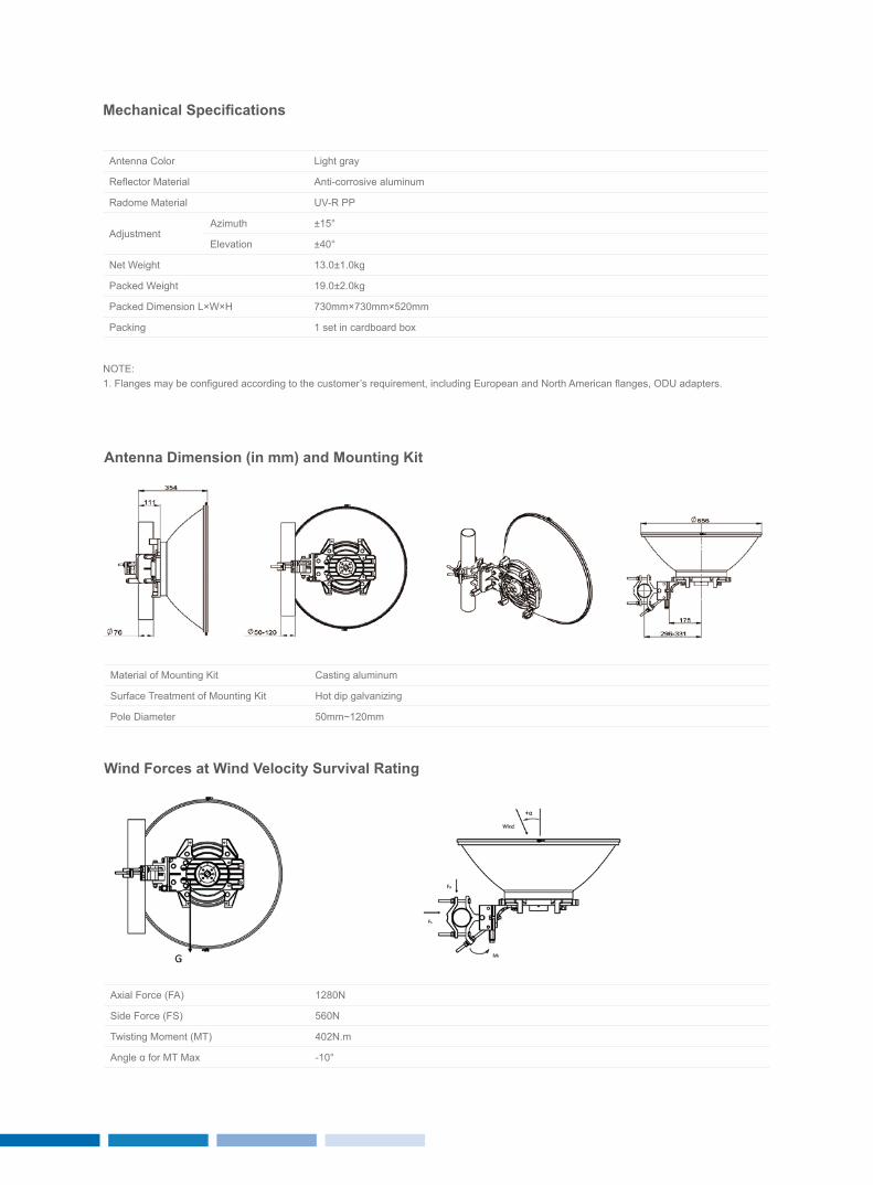
Mechanical Specifications
Antenna Color Light gray
Reflector Material Anti-corrosive aluminum
Radome Material UV-R PP
Adjustment Azimuth ±15°
Elevation ±40°
Net Weight 13.0±1.0kg
Packed Weight 19.0±2.0kg
Packed Dimension L×W×H 730mm×730mm×520mm
Packing 1 set in cardboard box
NOTE:1. Flanges may be configured according to the customer’s requirement, including European and North American flanges, ODU adapters.
Antenna Dimension (in mm) and Mounting Kit
wind Forces at wind velocity Survival rating
Material of Mounting Kit Casting aluminum
Surface Treatment of Mounting Kit Hot dip galvanizing
Pole Diameter 50mm~120mm
Axial Force (FA) 1280N
Side Force (FS) 560N
Twisting Moment (MT) 402N.m
Angle α for MT Max -10°
1615
• High performance• Single or dual polarization • Low profile• ETSI Class2 (Class3)• High reliability• Simple installation
Main Features
0.9M MIcrowAVE AntEnnAS
MICrowAve AnTennAS
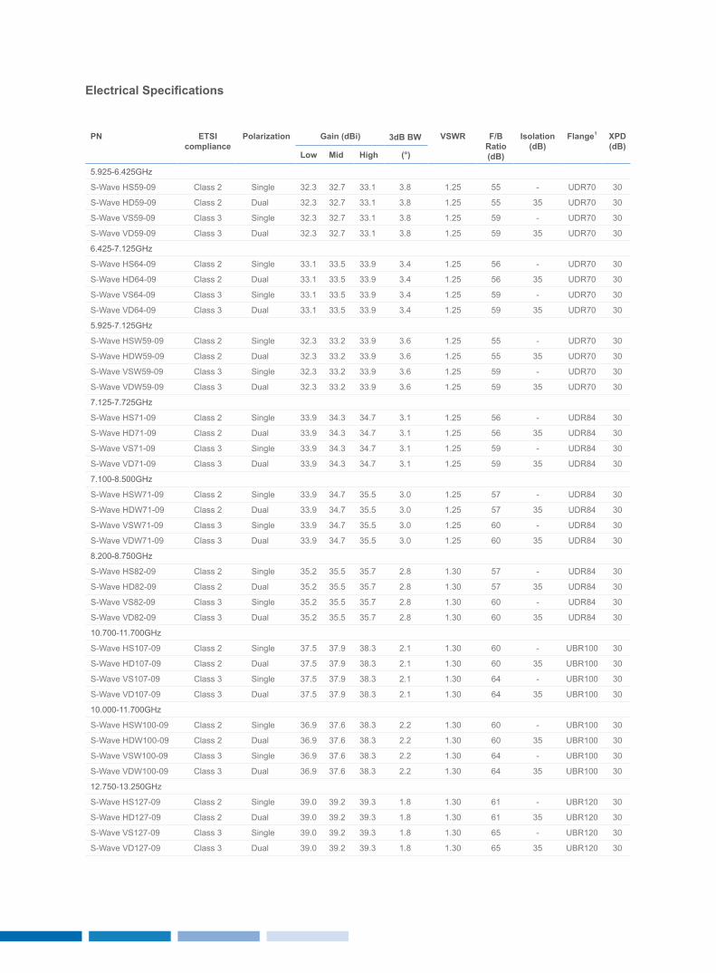
Electrical Specifications
Pn eTSI compliance
Polarization Gain (dBi) 3dB Bw vSwr F/B ratio(dB)
Isolation(dB)
Flange1 XPD(dB)
Low Mid High (°)
5.925-6.425GHz
S-Wave HS59-09 Class 2 Single 32.3 32.7 33.1 3.8 1.25 55 - UDR70 30
S-Wave HD59-09 Class 2 Dual 32.3 32.7 33.1 3.8 1.25 55 35 UDR70 30
S-Wave VS59-09 Class 3 Single 32.3 32.7 33.1 3.8 1.25 59 - UDR70 30
S-Wave VD59-09 Class 3 Dual 32.3 32.7 33.1 3.8 1.25 59 35 UDR70 30
6.425-7.125GHz
S-Wave HS64-09 Class 2 Single 33.1 33.5 33.9 3.4 1.25 56 - UDR70 30
S-Wave HD64-09 Class 2 Dual 33.1 33.5 33.9 3.4 1.25 56 35 UDR70 30
S-Wave VS64-09 Class 3 Single 33.1 33.5 33.9 3.4 1.25 59 - UDR70 30
S-Wave VD64-09 Class 3 Dual 33.1 33.5 33.9 3.4 1.25 59 35 UDR70 30
5.925-7.125GHz
S-Wave HSW59-09 Class 2 Single 32.3 33.2 33.9 3.6 1.25 55 - UDR70 30
S-Wave HDW59-09 Class 2 Dual 32.3 33.2 33.9 3.6 1.25 55 35 UDR70 30
S-Wave VSW59-09 Class 3 Single 32.3 33.2 33.9 3.6 1.25 59 - UDR70 30
S-Wave VDW59-09 Class 3 Dual 32.3 33.2 33.9 3.6 1.25 59 35 UDR70 30
7.125-7.725GHz
S-Wave HS71-09 Class 2 Single 33.9 34.3 34.7 3.1 1.25 56 - UDR84 30
S-Wave HD71-09 Class 2 Dual 33.9 34.3 34.7 3.1 1.25 56 35 UDR84 30
S-Wave VS71-09 Class 3 Single 33.9 34.3 34.7 3.1 1.25 59 - UDR84 30
S-Wave VD71-09 Class 3 Dual 33.9 34.3 34.7 3.1 1.25 59 35 UDR84 30
7.100-8.500GHz
S-Wave HSW71-09 Class 2 Single 33.9 34.7 35.5 3.0 1.25 57 - UDR84 30
S-Wave HDW71-09 Class 2 Dual 33.9 34.7 35.5 3.0 1.25 57 35 UDR84 30
S-Wave VSW71-09 Class 3 Single 33.9 34.7 35.5 3.0 1.25 60 - UDR84 30
S-Wave VDW71-09 Class 3 Dual 33.9 34.7 35.5 3.0 1.25 60 35 UDR84 30
8.200-8.750GHz
S-Wave HS82-09 Class 2 Single 35.2 35.5 35.7 2.8 1.30 57 - UDR84 30
S-Wave HD82-09 Class 2 Dual 35.2 35.5 35.7 2.8 1.30 57 35 UDR84 30
S-Wave VS82-09 Class 3 Single 35.2 35.5 35.7 2.8 1.30 60 - UDR84 30
S-Wave VD82-09 Class 3 Dual 35.2 35.5 35.7 2.8 1.30 60 35 UDR84 30
10.700-11.700GHz
S-Wave HS107-09 Class 2 Single 37.5 37.9 38.3 2.1 1.30 60 - UBR100 30
S-Wave HD107-09 Class 2 Dual 37.5 37.9 38.3 2.1 1.30 60 35 UBR100 30
S-Wave VS107-09 Class 3 Single 37.5 37.9 38.3 2.1 1.30 64 - UBR100 30
S-Wave VD107-09 Class 3 Dual 37.5 37.9 38.3 2.1 1.30 64 35 UBR100 30
10.000-11.700GHz
S-Wave HSW100-09 Class 2 Single 36.9 37.6 38.3 2.2 1.30 60 - UBR100 30
S-Wave HDW100-09 Class 2 Dual 36.9 37.6 38.3 2.2 1.30 60 35 UBR100 30
S-Wave VSW100-09 Class 3 Single 36.9 37.6 38.3 2.2 1.30 64 - UBR100 30
S-Wave VDW100-09 Class 3 Dual 36.9 37.6 38.3 2.2 1.30 64 35 UBR100 30
12.750-13.250GHz
S-Wave HS127-09 Class 2 Single 39.0 39.2 39.3 1.8 1.30 61 - UBR120 30
S-Wave HD127-09 Class 2 Dual 39.0 39.2 39.3 1.8 1.30 61 35 UBR120 30
S-Wave VS127-09 Class 3 Single 39.0 39.2 39.3 1.8 1.30 65 - UBR120 30
S-Wave VD127-09 Class 3 Dual 39.0 39.2 39.3 1.8 1.30 65 35 UBR120 30
1817
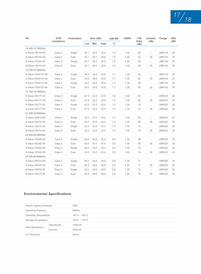
Environmental Specifications
Feeder Ingress Protection IP65
Operating Pressure 50KPa
Operating Temperature -45°C ~ +60°C
Storage Temperature -55°C ~ +70°C
Wind Resistance Operational 126km/h
Survival 200km/h
Ice Thickness 25mm
Pn eTSI compliance
Polarization Gain (dBi) 3dB Bw vSwr F/B ratio(dB)
Isolation(dB)
Flange1 XPD(dB)
Low Mid High (°)
14.400-15.350GHz
S-Wave HS144-09 Class 2 Single 40.1 40.3 40.6 1.6 1.30 62 - UBR140 30
S-Wave HD144-09 Class 2 Dual 40.1 40.3 40.6 1.6 1.30 62 35 UBR140 30
S-Wave VS144-09 Class 3 Single 40.1 40.3 40.6 1.6 1.30 68 - UBR140 30
S-Wave VD144-09 Class 3 Dual 40.1 40.3 40.6 1.6 1.30 68 35 UBR140 30
12.750-15.350GHz
S-Wave HSW127-09 Class 2 Single 39.0 39.8 40.6 1.7 1.30 62 - UBR140 30
S-Wave HDW127-09 Class 2 Dual 39.0 39.8 40.6 1.7 1.30 62 35 UBR140 30
S-Wave VSW127-09 Class 3 Single 39.0 39.8 40.6 1.7 1.30 66 - UBR140 30
S-Wave VDW127-09 Class 3 Dual 39.0 39.8 40.6 1.7 1.30 66 35 UBR140 30
17.700-19.700GHz
S-Wave HS177-09 Class 2 Single 41.9 42.3 42.8 1.2 1.30 64 - UBR220 30
S-Wave HD177-09 Class 2 Dual 41.9 42.3 42.8 1.2 1.30 64 35 UBR220 30
S-Wave VS177-09 Class 3 Single 41.9 42.3 42.8 1.2 1.30 70 - UBR220 30
S-Wave VD177-09 Class 3 Dual 41.9 42.3 42.8 1.2 1.30 70 35 UBR220 30
21.200-23.600GHz
S-Wave HS212-09 Class 2 Single 43.4 43.9 44.4 1.0 1.30 66 - UBR220 30
S-Wave HD212-09 Class 2 Dual 43.4 43.9 44.4 1.0 1.30 66 35 UBR220 30
S-Wave VS212-09 Class 3 Single 43.4 43.9 44.4 1.0 1.30 72 - UBR220 30
S-Wave VD212-09 Class 3 Dual 43.4 43.9 44.4 1.0 1.30 72 35 UBR220 30
24.250-26.500GHz
S-Wave HS242-09 Class 2 Single 44.6 45.0 45.4 0.8 1.30 68 - UBR320 30
S-Wave HD242-09 Class 2 Dual 44.6 45.0 45.4 0.8 1.30 68 35 UBR320 30
S-Wave VS242-09 Class 3 Single 44.6 45.0 45.4 0.8 1.30 73 - UBR320 30
S-Wave VD242-09 Class 3 Dual 44.6 45.0 45.4 0.8 1.30 73 35 UBR320 30
37.000-40.000GHz
S-Wave HS370-09 Class 2 Single 48.3 48.6 48.9 0.6 1.30 71 - UBR320 30
S-Wave HD370-09 Class 2 Dual 48.3 48.6 48.9 0.6 1.30 71 35 UBR320 30
S-Wave VS370-09 Class 3 Single 48.3 48.6 48.9 0.6 1.30 75 - UBR320 30
S-Wave VD370-09 Class 3 Dual 48.3 48.6 48.9 0.6 1.30 75 35 UBR320 30
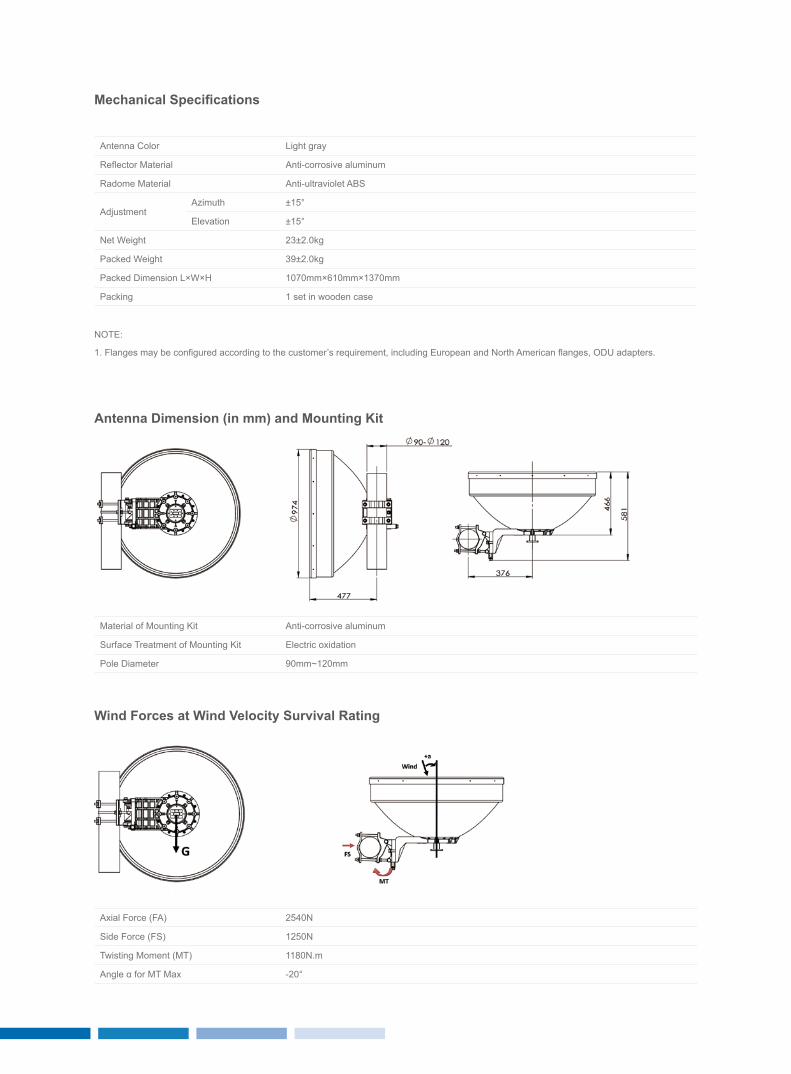
Mechanical Specifications
Antenna Color Light gray
Reflector Material Anti-corrosive aluminum
Radome Material Anti-ultraviolet ABS
Adjustment Azimuth ±15°
Elevation ±15°
Net Weight 23±2.0kg
Packed Weight 39±2.0kg
Packed Dimension L×W×H 1070mm×610mm×1370mm
Packing 1 set in wooden case
NOTE:
1. Flanges may be configured according to the customer’s requirement, including European and North American flanges, ODU adapters.
Antenna Dimension (in mm) and Mounting Kit
wind Forces at wind velocity Survival rating
Material of Mounting Kit Anti-corrosive aluminum
Surface Treatment of Mounting Kit Electric oxidation
Pole Diameter 90mm~120mm
Axial Force (FA) 2540N
Side Force (FS) 1250N
Twisting Moment (MT) 1180N.m
Angle α for MT Max -20°
2019
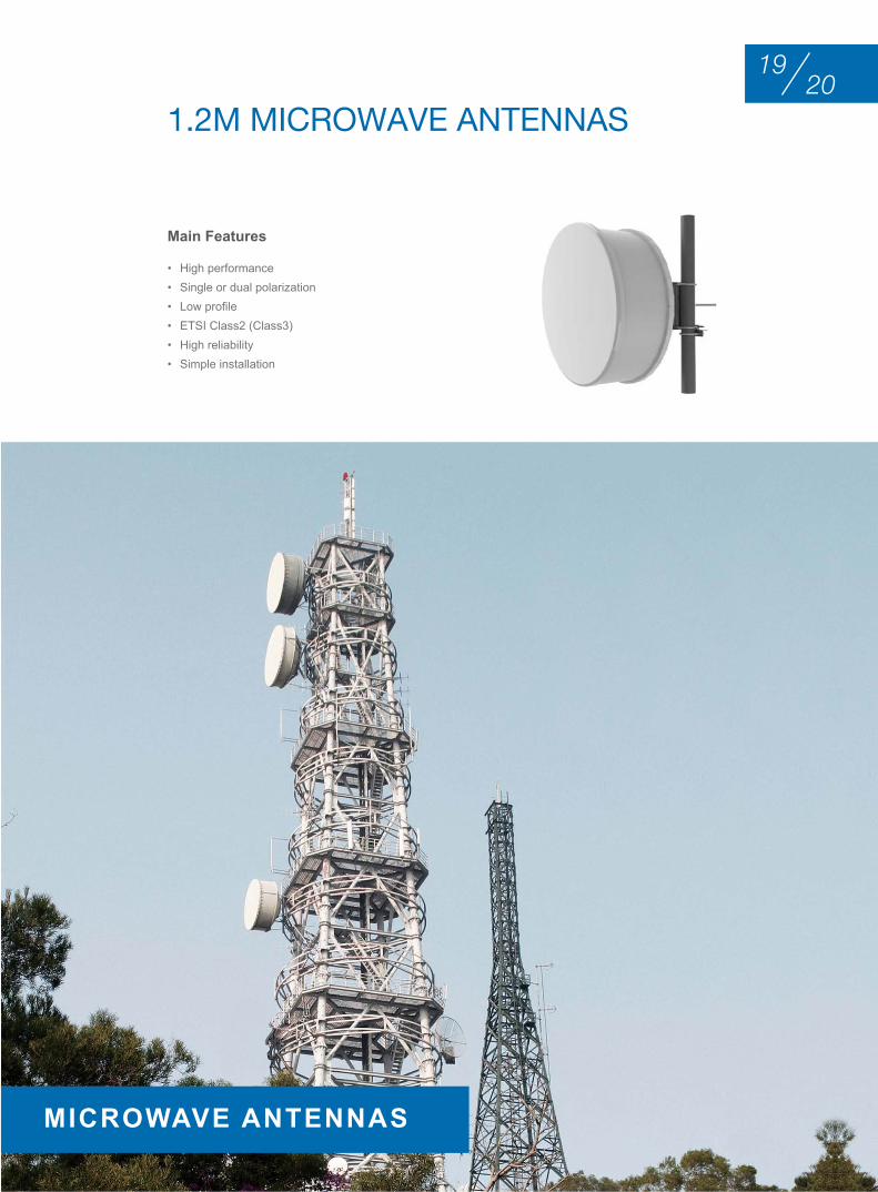
• High performance• Single or dual polarization• Low profile • ETSI Class2 (Class3)• High reliability• Simple installation
Main Features
1.2M MIcrowAVE AntEnnAS
MICrowAve AnTennAS

Electrical Specifications
Pn eTSI compliance
Polarization Gain (dBi) 3dB Bw vSwr F/B ratio(dB)
Isolation(dB)
Flange1 XPD(dB)
Low Mid High (°)
5.925-6.425GHz
S-Wave HS59-12 Class 2 Single 34.8 35.2 35.6 2.8 1.20 57 - UDR70 30
S-Wave HD59-12 Class 2 Dual 34.8 35.2 35.6 2.8 1.20 57 35 UDR70 30
S-Wave VS59-12 Class 3 Single 34.8 35.2 35.6 2.8 1.20 60 - UDR70 30
S-Wave VD59-12 Class 3 Dual 34.8 35.2 35.6 2.8 1.20 60 35 UDR70 30
6.425-7.125GHz
S-Wave HS64-12 Class 2 Single 35.5 36.0 36.4 2.6 1.20 58 - UDR70 30
S-Wave HD64-12 Class 2 Dual 35.5 36.0 36.4 2.6 1.20 58 35 UDR70 30
S-Wave VS64-12 Class 3 Single 35.5 36.0 36.4 2.6 1.20 61 - UDR70 30
S-Wave VD64-12 Class 3 Dual 35.5 36.0 36.4 2.6 1.20 61 35 UDR70 30
5.925-7.125GHz
S-Wave HSW59-12 Class 2 Single 34.8 35.2 35.6 2.7 1.20 58 - UDR70 30
S-Wave HDW59-12 Class 2 Dual 34.8 35.2 35.6 2.7 1.20 58 35 UDR70 30
S-Wave VSW59-12 Class 3 Single 34.8 35.2 35.6 2.7 1.20 61 - UDR70 30
S-Wave VDW59-12 Class 3 Dual 34.8 35.2 35.6 2.7 1.20 61 35 UDR70 30
7.125-7.725GHz
S-Wave HS71-12 Class 2 Single 36.4 36.8 37.2 2.4 1.20 59 - UDR84 30
S-Wave HD71-12 Class 2 Dual 36.4 36.8 37.2 2.4 1.20 59 35 UDR84 30
S-Wave VS71-12 Class 3 Single 36.4 36.8 37.2 2.4 1.20 62 - UDR84 30
S-Wave VD71-12 Class 3 Dual 36.4 36.8 37.2 2.4 1.20 62 35 UDR84 30
7.100-8.500GHz
S-Wave HSW71-12 Class 2 Single 36.4 37.2 38.0 2.2 1.30 59 - UDR84 30
S-Wave HDW71-12 Class 2 Dual 36.4 37.2 38.0 2.2 1.30 59 35 UDR84 30
S-Wave VSW71-12 Class 3 Single 36.4 37.2 38.0 2.2 1.30 63 - UDR84 30
S-Wave VDW71-12 Class 3 Dual 36.4 37.2 38.0 2.2 1.30 63 35 UDR84 30
8.200-8.750GHz
S-Wave HS82-12 Class 2 Single 37.7 38.0 38.2 2.1 1.15 60 - UDR84 30
S-Wave HD82-12 Class 2 Dual 37.7 38.0 38.2 2.1 1.15 60 35 UDR84 30
S-Wave VS82-12 Class 3 Single 37.7 38.0 38.2 2.1 1.15 63 - UDR84 30
S-Wave VD82-12 Class 3 Dual 37.7 38.0 38.2 2.1 1.15 63 35 UDR84 30
10.700-11.700GHz
S-Wave HS107-12 Class 2 Single 40.0 40.4 40.8 1.6 1.15 62 - UBR100 30
S-Wave HD107-12 Class 2 Dual 40.0 40.4 40.8 1.6 1.15 62 35 UBR100 30
S-Wave VS107-12 Class 3 Single 40.0 40.4 40.8 1.6 1.15 66 - UBR100 30
S-Wave VD107-12 Class 3 Dual 40.0 40.4 40.8 1.6 1.15 66 35 UBR100 30
10.000-11.700GHz
S-Wave HSW100-12 Class 2 Single 39.4 40.1 40.8 1.6 1.15 62 - UBR100 30
S-Wave HDW100-12 Class 2 Dual 39.4 40.1 40.8 1.6 1.15 62 35 UBR100 30
S-Wave VSW100-12 Class 3 Single 39.4 40.1 40.8 1.6 1.15 66 - UBR100 30
S-Wave VDW100-12 Class 3 Dual 39.4 40.1 40.8 1.6 1.15 66 35 UBR100 30
12.750-13.250GHz
S-Wave HS127-12 Class 2 Single 41.5 41.7 41.8 1.3 1.15 64 - UBR120 30
S-Wave HD127-12 Class 2 Dual 41.5 41.7 41.8 1.3 1.15 64 35 UBR120 30
S-Wave VS127-12 Class 3 Single 41.5 41.7 41.8 1.3 1.15 67 - UBR120 30
S-Wave VD127-12 Class 3 Dual 41.5 41.7 41.8 1.3 1.15 67 35 UBR120 30
2221
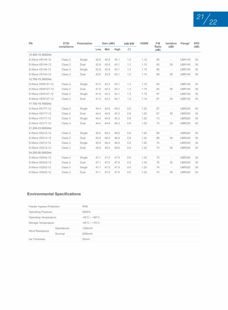
Environmental Specifications
Feeder Ingress Protection IP65
Operating Pressure 50KPa
Operating Temperature -45°C ~ +60°C
Storage Temperature -55°C ~ +70°C
Wind Resistance Operational 126km/h
Survival 200km/h
Ice Thickness 25mm
Pn eTSI compliance
Polarization Gain (dBi) 3dB Bw vSwr F/B ratio(dB)
Isolation(dB)
Flange1 XPD(dB)
Low Mid High (°)
14.400-15.350GHz
S-Wave HS144-12 Class 2 Single 42.6 42.8 43.1 1.2 1.15 65 - UBR140 30
S-Wave HD144-12 Class 2 Dual 42.6 42.8 43.1 1.2 1.15 65 35 UBR140 30
S-Wave VS144-12 Class 3 Single 42.6 42.8 43.1 1.2 1.15 68 - UBR140 30
S-Wave VD144-12 Class 3 Dual 42.6 42.8 43.1 1.2 1.15 68 35 UBR140 30
12.750-15.350GHz
S-Wave HSW127-12 Class 2 Single 41.5 42.3 43.1 1.3 1.15 64 - UBR140 30
S-Wave HDW127-12 Class 2 Dual 41.5 42.3 43.1 1.3 1.15 64 35 UBR140 30
S-Wave VSW127-12 Class 3 Single 41.5 42.3 43.1 1.3 1.15 67 - UBR140 30
S-Wave VDW127-12 Class 3 Dual 41.5 42.3 43.1 1.3 1.15 67 35 UBR140 30
17.700-19.700GHz
S-Wave HS177-12 Class 2 Single 44.4 44.8 45.3 0.9 1.20 67 - UBR220 30
S-Wave HD177-12 Class 2 Dual 44.4 44.8 45.3 0.9 1.20 67 35 UBR220 30
S-Wave VS177-12 Class 3 Single 44.4 44.8 45.3 0.9 1.20 73 - UBR220 30
S-Wave VD177-12 Class 3 Dual 44.4 44.8 45.3 0.9 1.20 73 35 UBR220 30
21.200-23.600GHz
S-Wave HS212-12 Class 2 Single 45.9 46.4 46.9 0.8 1.20 68 - UBR220 30
S-Wave HD212-12 Class 2 Dual 45.9 46.4 46.9 0.8 1.20 68 35 UBR220 30
S-Wave VS212-12 Class 3 Single 45.9 46.4 46.9 0.8 1.20 74 - UBR220 30
S-Wave VD212-12 Class 3 Dual 45.9 46.4 46.9 0.8 1.20 74 35 UBR220 30
24.250-26.500GHz
S-Wave HS242-12 Class 2 Single 47.1 47.5 47.9 0.6 1.25 70 - UBR320 30
S-Wave HD242-12 Class 2 Dual 47.1 47.5 47.9 0.6 1.25 70 35 UBR320 30
S-Wave VS242-12 Class 3 Single 47.1 47.5 47.9 0.6 1.25 74 - UBR320 30
S-Wave VD242-12 Class 3 Dual 47.1 47.5 47.9 0.6 1.25 74 35 UBR320 30
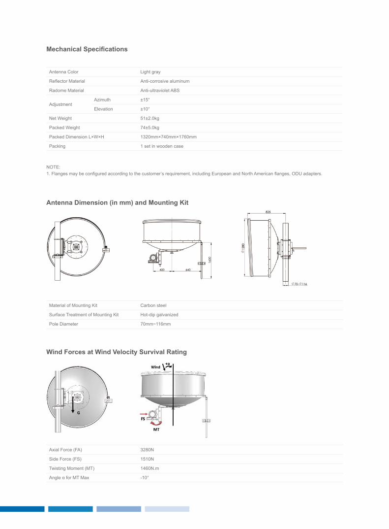
Mechanical Specifications
Antenna Color Light gray
Reflector Material Anti-corrosive aluminum
Radome Material Anti-ultraviolet ABS
Adjustment Azimuth ±15°
Elevation ±10°
Net Weight 51±2.0kg
Packed Weight 74±5.0kg
Packed Dimension L×W×H 1320mm×740mm×1760mm
Packing 1 set in wooden case
NOTE:1. Flanges may be configured according to the customer’s requirement, including European and North American flanges, ODU adapters.
Antenna Dimension (in mm) and Mounting Kit
wind Forces at wind velocity Survival rating
Material of Mounting Kit Carbon steel
Surface Treatment of Mounting Kit Hot-dip galvanized
Pole Diameter 70mm~116mm
Axial Force (FA) 3280N
Side Force (FS) 1510N
Twisting Moment (MT) 1460N.m
Angle α for MT Max -10°
2423
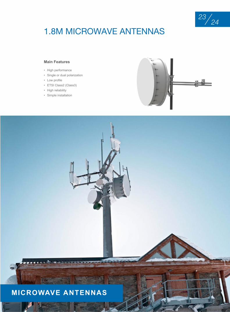
• High performance• Single or dual polarization• Low profile • ETSI Class2 (Class3)• High reliability• Simple installation
Main Features
1.8M MIcrowAVE AntEnnAS
MICrowAve AnTennAS
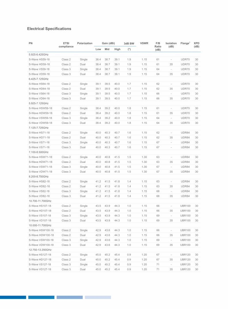
Electrical Specifications
Pn eTSI compliance
Polarization Gain (dBi) 3dB Bw vSwr F/B ratio(dB)
Isolation(dB)
Flange1 XPD(dB)
Low Mid High (°)
5.925-6.425GHz
S-Wave HS59-18 Class 2 Single 38.4 38.7 39.1 1.9 1.15 61 - UDR70 30
S-Wave HD59-18 Class 2 Dual 38.4 38.7 39.1 1.9 1.15 61 35 UDR70 30
S-Wave VS59-18 Class 3 Single 38.4 38.7 39.1 1.9 1.15 64 - UDR70 30
S-Wave VD59-18 Class 3 Dual 38.4 38.7 39.1 1.9 1.15 64 35 UDR70 30
6.425-7.125GHz
S-Wave HS64-18 Class 2 Single 39.1 39.5 40.0 1.7 1.15 62 - UDR70 30
S-Wave HD64-18 Class 2 Dual 39.1 39.5 40.0 1.7 1.15 62 35 UDR70 30
S-Wave VS64-18 Class 3 Single 39.1 39.5 40.0 1.7 1.15 66 - UDR70 30
S-Wave VD64-18 Class 3 Dual 39.1 39.5 40.0 1.7 1.15 66 35 UDR70 30
5.925-7.125GHz
S-Wave HSW59-18 Class 2 Single 38.4 39.2 40.0 1.8 1.15 61 - UDR70 30
S-Wave HDW59-18 Class 2 Dual 38.4 39.2 40.0 1.8 1.15 61 35 UDR70 30
S-Wave VSW59-18 Class 3 Single 38.4 39.2 40.0 1.8 1.15 64 - UDR70 30
S-Wave VDW59-18 Class 3 Dual 38.4 39.2 40.0 1.8 1.15 64 35 UDR70 30
7.125-7.725GHz
S-Wave HS71-18 Class 2 Single 40.0 40.3 40.7 1.6 1.15 62 - UDR84 30
S-Wave HD71-18 Class 2 Dual 40.0 40.3 40.7 1.6 1.15 62 35 UDR84 30
S-Wave VS71-18 Class 3 Single 40.0 40.3 40.7 1.6 1.15 67 - UDR84 30
S-Wave VS71-18 Class 3 Dual 40.0 40.3 40.7 1.6 1.15 67 - UDR84 30
7.100-8.500GHz
S-Wave HSW71-18 Class 2 Single 40.0 40.8 41.5 1.5 1.30 63 - UDR84 30
S-Wave HDW71-18 Class 2 Dual 40.0 40.8 41.5 1.5 1.30 63 35 UDR84 30
S-Wave VSW71-18 Class 3 Single 40.0 40.8 41.5 1.5 1.30 67 - UDR84 30
S-Wave VDW71-18 Class 3 Dual 40.0 40.8 41.5 1.5 1.30 67 35 UDR84 30
8.200-8.750GHz
S-Wave HS82-18 Class 2 Single 41.2 41.5 41.8 1.4 1.15 63 - UDR84 30
S-Wave HD82-18 Class 2 Dual 41.2 41.5 41.8 1.4 1.15 63 35 UDR84 30
S-Wave VS82-18 Class 3 Single 41.2 41.5 41.8 1.4 1.15 68 - UDR84 30
S-Wave VD82-18 Class 3 Dual 41.2 41.5 41.8 1.4 1.15 68 35 UDR84 30
10.700-11.700GHz
S-Wave HS107-18 Class 2 Single 43.5 43.9 44.3 1.0 1.15 66 - UBR100 30
S-Wave HD107-18 Class 2 Dual 43.5 43.9 44.3 1.0 1.15 66 35 UBR100 30
S-Wave VS107-18 Class 3 Single 43.5 43.9 44.3 1.0 1.15 69 - UBR100 30
S-Wave VD107-18 Class 3 Dual 43.5 43.9 44.3 1.0 1.15 69 35 UBR100 30
10.000-11.700GHz
S-Wave HSW100-18 Class 2 Single 42.9 43.6 44.3 1.0 1.15 66 - UBR100 30
S-Wave HDW100-18 Class 2 Dual 42.9 43.6 44.3 1.0 1.15 66 35 UBR100 30
S-Wave VSW100-18 Class 3 Single 42.9 43.6 44.3 1.0 1.15 69 - UBR100 30
S-Wave VDW100-18 Class 3 Dual 42.9 43.6 44.3 1.0 1.15 69 35 UBR100 30
12.750-13.250GHz
S-Wave HS127-18 Class 2 Single 45.0 45.2 45.4 0.9 1.20 67 - UBR120 30
S-Wave HD127-18 Class 2 Dual 45.0 45.2 45.4 0.9 1.20 67 35 UBR120 30
S-Wave VS127-18 Class 3 Single 45.0 45.2 45.4 0.9 1.20 71 - UBR120 30
S-Wave VD127-18 Class 3 Dual 45.0 45.2 45.4 0.9 1.20 71 35 UBR120 30
2625
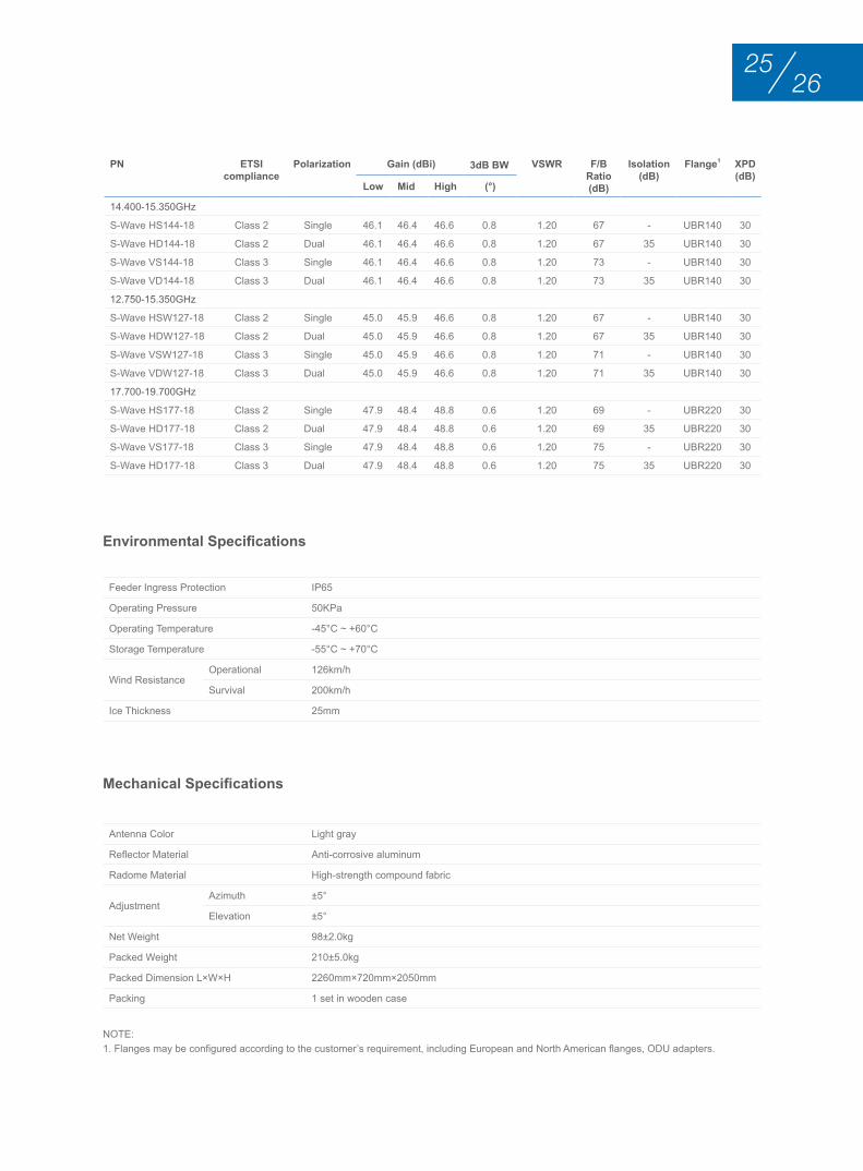
Environmental Specifications
Mechanical Specifications
Feeder Ingress Protection IP65
Operating Pressure 50KPa
Operating Temperature -45°C ~ +60°C
Storage Temperature -55°C ~ +70°C
Wind Resistance Operational 126km/h
Survival 200km/h
Ice Thickness 25mm
Antenna Color Light gray
Reflector Material Anti-corrosive aluminum
Radome Material High-strength compound fabric
Adjustment Azimuth ±5°
Elevation ±5°
Net Weight 98±2.0kg
Packed Weight 210±5.0kg
Packed Dimension L×W×H 2260mm×720mm×2050mm
Packing 1 set in wooden case
NOTE:1. Flanges may be configured according to the customer’s requirement, including European and North American flanges, ODU adapters.
Pn eTSI compliance
Polarization Gain (dBi) 3dB Bw vSwr F/B ratio(dB)
Isolation(dB)
Flange1 XPD(dB)
Low Mid High (°)
14.400-15.350GHz
S-Wave HS144-18 Class 2 Single 46.1 46.4 46.6 0.8 1.20 67 - UBR140 30
S-Wave HD144-18 Class 2 Dual 46.1 46.4 46.6 0.8 1.20 67 35 UBR140 30
S-Wave VS144-18 Class 3 Single 46.1 46.4 46.6 0.8 1.20 73 - UBR140 30
S-Wave VD144-18 Class 3 Dual 46.1 46.4 46.6 0.8 1.20 73 35 UBR140 30
12.750-15.350GHz
S-Wave HSW127-18 Class 2 Single 45.0 45.9 46.6 0.8 1.20 67 - UBR140 30
S-Wave HDW127-18 Class 2 Dual 45.0 45.9 46.6 0.8 1.20 67 35 UBR140 30
S-Wave VSW127-18 Class 3 Single 45.0 45.9 46.6 0.8 1.20 71 - UBR140 30
S-Wave VDW127-18 Class 3 Dual 45.0 45.9 46.6 0.8 1.20 71 35 UBR140 30
17.700-19.700GHz
S-Wave HS177-18 Class 2 Single 47.9 48.4 48.8 0.6 1.20 69 - UBR220 30
S-Wave HD177-18 Class 2 Dual 47.9 48.4 48.8 0.6 1.20 69 35 UBR220 30
S-Wave VS177-18 Class 3 Single 47.9 48.4 48.8 0.6 1.20 75 - UBR220 30
S-Wave HD177-18 Class 3 Dual 47.9 48.4 48.8 0.6 1.20 75 35 UBR220 30
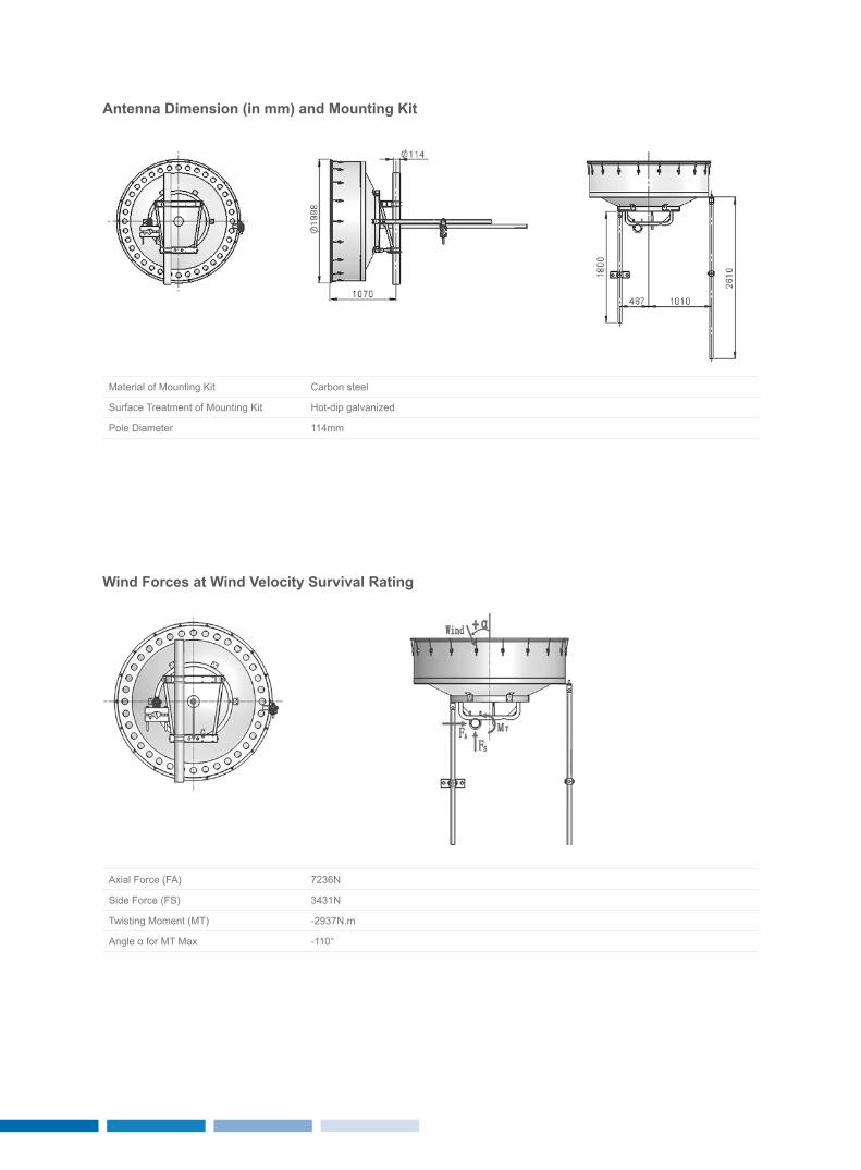
Antenna Dimension (in mm) and Mounting Kit
wind Forces at wind velocity Survival rating
Material of Mounting Kit Carbon steel
Surface Treatment of Mounting Kit Hot-dip galvanized
Pole Diameter 114mm
Axial Force (FA) 7236N
Side Force (FS) 3431N
Twisting Moment (MT) -2937N.m
Angle α for MT Max -110°
2827
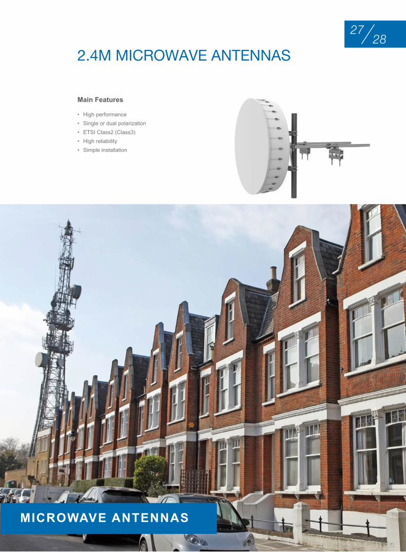
• High performance• Single or dual polarization• ETSI Class2 (Class3)• High reliability• Simple installation
Main Features
2.4M MIcrowAVE AntEnnAS
MICrowAve AnTennAS
Electrical Specifications
Pn eTSI compliance
Polarization Gain (dBi) 3dB Bw vSwr F/B ratio(dB)
Isolation(dB)
Flange1 XPD(dB)
Low Mid High (°)
5.925-6.425GHz
S-Wave HS59-24 Class 2 Single 40.9 41.2 41.6 1.4 1.15 61 - UDR70 30
S-Wave HD59-24 Class 2 Dual 40.9 41.2 41.6 1.4 1.15 61 35 UDR70 30
S-Wave VS59-24 Class 3 Single 40.9 41.2 41.6 1.4 1.15 68 - UDR70 30
S-Wave VD59-24 Class 3 Dual 40.9 41.2 41.6 1.4 1.15 68 35 UDR70 30
6.425-7.125GHz
S-Wave HS64-24 Class 2 Single 41.6 42.0 42.5 1.3 1.15 62 - UDR70 30
S-Wave HD64-24 Class 2 Dual 41.6 42.0 42.5 1.3 1.15 62 35 UDR70 30
S-Wave VS64-24 Class 3 Single 41.6 42.0 42.5 1.3 1.15 69 - UDR70 30
S-Wave VD64-24 Class 3 Dual 41.6 42.0 42.5 1.3 1.15 69 35 UDR70 30
5.925-7.125GHz
S-Wave HSW59-24 Class 2 Single 40.9 41.7 42.5 1.3 1.15 62 - UDR70 30
S-Wave HDW59-24 Class 2 Dual 40.9 41.7 42.5 1.3 1.15 62 35 UDR70 30
S-Wave VSW59-24 Class 3 Single 40.9 41.7 42.5 1.3 1.15 69 - UDR70 30
S-Wave VDW59-24 Class 3 Dual 40.9 41.7 42.5 1.3 1.15 69 35 UDR70 30
7.125-7.725GHz
S-Wave HS71-24 Class 2 Single 42.5 42.8 43.2 1.2 1.15 62 - UDR84 30
S-Wave HD71-24 Class 2 Dual 42.5 42.8 43.2 1.2 1.15 62 35 UDR84 30
S-Wave VS71-24 Class 3 Single 42.5 42.8 43.2 1.2 1.15 69 - UDR84 30
S-Wave VD71-24 Class 3 Dual 42.5 42.8 43.2 1.2 1.15 69 35 UDR84 30
7.100-8.500GHz
S-Wave HSW71-24 Class 2 Single 42.5 43.3 44.0 1.1 1.30 63 - UDR84 30
S-Wave HDW71-24 Class 2 Dual 42.5 43.3 44.0 1.1 1.30 63 35 UDR84 30
S-Wave VSW71-24 Class 3 Single 42.5 43.3 44.0 1.1 1.30 69 - UDR84 30
S-Wave VDW71-24 Class 3 Dual 42.5 43.3 44.0 1.1 1.30 69 35 UDR84 30
8.200-8.750GHz
S-Wave HS82-24 Class 2 Single 43.7 44.0 44.3 1.0 1.15 63 - UDR84 30
S-Wave HD82-24 Class 2 Dual 43.7 44.0 44.3 1.0 1.15 63 35 UDR84 30
S-Wave VS82-24 Class 3 Single 43.7 44.0 44.3 1.0 1.15 69 - UDR84 30
S-Wave VD82-24 Class 3 Dual 43.7 44.0 44.3 1.0 1.15 69 35 UDR84 30
10.700-11.700GHz
S-Wave HS107-24 Class 2 Single 46.0 46.4 46.8 0.8 1.15 66 - UBR100 30
S-Wave HD107-24 Class 2 Dual 46.0 46.4 46.8 0.8 1.15 66 35 UBR100 30
S-Wave VS107-24 Class 3 Single 46.0 46.4 46.8 0.8 1.15 72 - UBR100 30
S-Wave VD107-24 Class 3 Dual 46.0 46.4 46.8 0.8 1.15 72 35 UBR100 30
10.000-11.700GHz
S-Wave HSW100-24 Class 2 Single 45.4 46.1 46.8 0.8 1.15 66 - UBR100 30
S-Wave HDW100-24 Class 2 Dual 45.4 46.1 46.8 0.8 1.15 66 35 UBR100 30
S-Wave VSW100-24 Class 3 Single 45.4 46.1 46.8 0.8 1.15 72 - UBR100 30
S-Wave VDW100-24 Class 3 Dual 45.4 46.1 46.8 0.8 1.15 72 35 UBR100 30
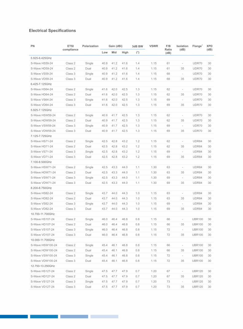
12.750-13.250GHz
S-Wave HS127-24 Class 2 Single 47.5 47.7 47.9 0.7 1.20 67 - UBR120 30
S-Wave HD127-24 Class 2 Dual 47.5 47.7 47.9 0.7 1.20 67 35 UBR120 30
S-Wave VS127-24 Class 3 Single 47.5 47.7 47.9 0.7 1.20 73 - UBR120 30
S-Wave VD127-24 Class 3 Dual 47.5 47.7 47.9 0.7 1.20 73 35 UBR120 30
3029
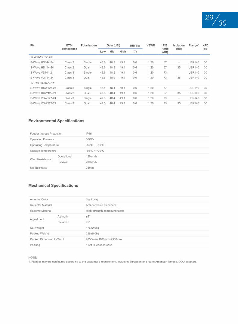
Environmental Specifications
Mechanical Specifications
Feeder Ingress Protection IP65
Operating Pressure 50KPa
Operating Temperature -45°C ~ +60°C
Storage Temperature -55°C ~ +70°C
Wind Resistance Operational 126km/h
Survival 200km/h
Ice Thickness 25mm
Antenna Color Light gray
Reflector Material Anti-corrosive aluminum
Radome Material High-strength compound fabric
Adjustment Azimuth ±5°
Elevation ±5°
Net Weight 176±2.0kg
Packed Weight 226±5.0kg
Packed Dimension L×W×H 2650mm×1100mm×2560mm
Packing 1 set in wooden case
NOTE:1. Flanges may be configured according to the customer’s requirement, including European and North American flanges, ODU adapters.
Pn eTSI compliance
Polarization Gain (dBi) 3dB Bw vSwr F/B ratio(dB)
Isolation(dB)
Flange1 XPD(dB)
Low Mid High (°)
14.400-15.350 GHz
S-Wave HS144-24 Class 2 Single 48.6 48.9 49.1 0.6 1.20 67 - UBR140 30
S-Wave HD144-24 Class 2 Dual 48.6 48.9 49.1 0.6 1.20 67 35 UBR140 30
S-Wave VS144-24 Class 3 Single 48.6 48.9 49.1 0.6 1.20 73 - UBR140 30
S-Wave VD144-24 Class 3 Dual 48.6 48.9 49.1 0.6 1.20 73 35 UBR140 30
12.750-15.350GHz
S-Wave HSW127-24 Class 2 Single 47.5 48.4 49.1 0.6 1.20 67 - UBR140 30
S-Wave HDW127-24 Class 2 Dual 47.5 48.4 49.1 0.6 1.20 67 35 UBR140 30
S-Wave VSW127-24 Class 3 Single 47.5 48.4 49.1 0.6 1.20 73 - UBR140 30
S-Wave VDW127-24 Class 3 Dual 47.5 48.4 49.1 0.6 1.20 73 35 UBR140 30
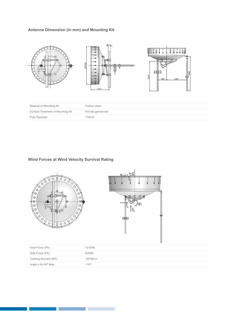
Antenna Dimension (in mm) and Mounting Kit
wind Forces at wind velocity Survival rating
Material of Mounting Kit Carbon steel
Surface Treatment of Mounting Kit Hot-dip galvanized
Pole Diameter 114mm
Axial Force (FA) 12100N
Side Force (FS) 6290N
Twisting Moment (MT) -5970N.m
Angle α for MT Max -110°
3231
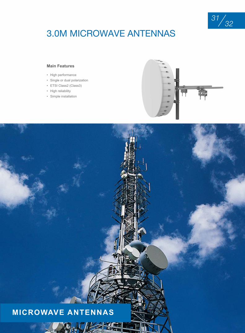
• High performance• Single or dual polarization• ETSI Class2 (Class3)• High reliability• Simple installation
Main Features
3.0M MIcrowAVE AntEnnAS
MICrowAve AnTennAS
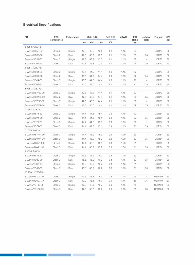
Electrical Specifications
Pn eTSI compliance
Polarization Gain (dBi) 3dB Bw vSwr F/B ratio(dB)
Isolation(dB)
Flange1 XPD(dB)
Low Mid High (°)
5.925-6.425GHz
S-Wave HS59-30 Class 2 Single 42.8 43.2 43.5 1.1 1.15 63 - UDR70 30
S-Wave HD59-30 Class 2 Dual 42.8 43.2 43.5 1.1 1.15 63 35 UDR70 30
S-Wave VS59-30 Class 3 Single 42.8 43.2 43.5 1.1 1.15 69 - UDR70 30
S-Wave VD59-30 Class 3 Dual 42.8 43.2 43.5 1.1 1.15 69 35 UDR70 30
6.425-7.125GHz
S-Wave HS64-30 Class 2 Single 43.5 44.0 44.4 1.0 1.15 62 - UDR70 30
S-Wave HD64-30 Class 2 Dual 43.5 44.0 44.4 1.0 1.15 62 35 UDR70 30
S-Wave VS64-30 Class 3 Single 43.5 44.0 44.4 1.0 1.15 70 - UDR70 30
S-Wave VD64-30 Class 3 Dual 43.5 44.0 44.4 1.0 1.15 70 35 UDR70 30
5.925-7.125GHz
S-Wave HSW59-30 Class 2 Single 42.8 43.6 44.4 1.1 1.15 63 - UDR70 30
S-Wave HDW59-30 Class 2 Dual 42.8 43.6 44.4 1.1 1.15 63 35 UDR70 30
S-Wave VSW59-30 Class 3 Single 42.8 43.6 44.4 1.1 1.15 69 - UDR70 30
S-Wave VDW59-30 Class 3 Dual 42.8 43.6 44.4 1.1 1.15 69 35 UDR70 30
7.125-7.725GHz
S-Wave HS71-30 Class 2 Single 44.4 44.8 45.1 0.9 1.15 62 - UDR84 30
S-Wave HD71-30 Class 2 Dual 44.4 44.8 45.1 0.9 1.15 62 35 UDR84 30
S-Wave VS71-30 Class 3 Single 44.4 44.8 45.1 0.9 1.15 70 - UDR84 30
S-Wave VD71-30 Class 3 Dual 44.4 44.8 45.1 0.9 1.15 70 35 UDR84 30
7.100-8.500GHz
S-Wave HSW71-30 Class 2 Single 44.4 45.2 45.9 0.9 1.30 63 - UDR84 30
S-Wave HDW71-30 Class 2 Dual 44.4 45.2 45.9 0.9 1.30 63 35 UDR84 30
S-WaveVSW71-30 Class 3 Single 44.4 45.2 45.9 0.9 1.30 71 - UDR84 30
S-WaveVDW71-30 Class 3 Dual 44.4 45.2 45.9 0.9 1.30 71 35 UDR84 30
8.200-8.750GHz
S-Wave HS82-30 Class 2 Single 45.6 45.9 46.2 0.8 1.15 63 - UDR84 30
S-Wave HD82-30 Class 2 Dual 45.6 45.9 46.2 0.8 1.15 63 35 UDR84 30
S-Wave VS82-30 Class 3 Single 45.6 45.9 46.2 0.8 1.15 71 - UDR84 30
S-Wave VD82-30 Class 3 Dual 45.6 45.9 46.2 0.8 1.15 71 35 UDR84 30
10.700-11.700GHz
S-Wave HS107-30 Class 2 Single 47.9 48.3 48.7 0.6 1.15 66 - UBR100 30
S-Wave HD107-30 Class 2 Dual 47.9 48.3 48.7 0.6 1.15 66 35 UBR100 30
S-Wave VS107-30 Class 3 Single 47.9 48.3 48.7 0.6 1.15 75 - UBR100 30
S-Wave VD107-30 Class 3 Dual 47.9 48.3 48.7 0.6 1.15 75 35 UBR100 30
3433
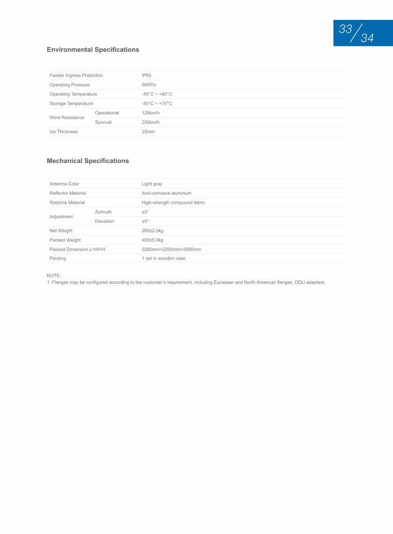
Environmental Specifications
Mechanical Specifications
Feeder Ingress Protection IP65
Operating Pressure 50KPa
Operating Temperature -45°C ~ +60°C
Storage Temperature -55°C ~ +70°C
Wind Resistance Operational 126km/h
Survival 200km/h
Ice Thickness 25mm
Antenna Color Light gray
Reflector Material Anti-corrosive aluminum
Radome Material High-strength compound fabric
Adjustment Azimuth ±5°
Elevation ±5°
Net Weight 260±2.0kg
Packed Weight 405±5.0kg
Packed Dimension L×W×H 3280mm×2250mm×2560mm
Packing 1 set in wooden case
NOTE:1. Flanges may be configured according to the customer’s requirement, including European and North American flanges, ODU adapters.
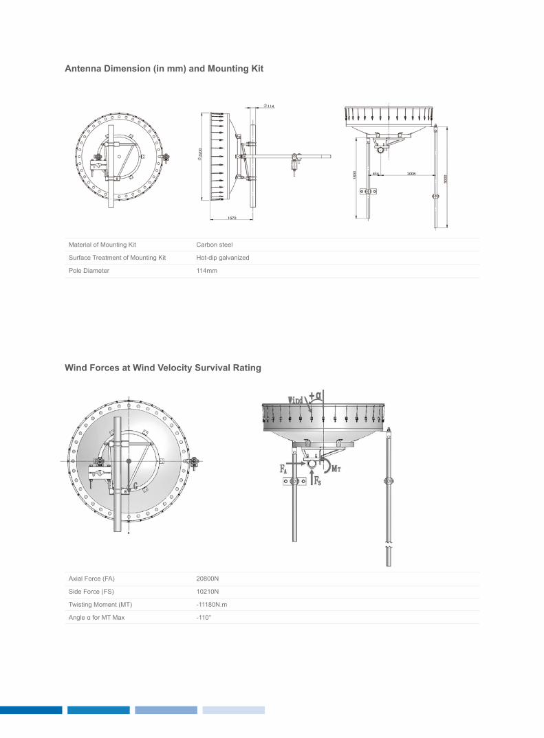
Antenna Dimension (in mm) and Mounting Kit
wind Forces at wind velocity Survival rating
Material of Mounting Kit Carbon steel
Surface Treatment of Mounting Kit Hot-dip galvanized
Pole Diameter 114mm
Axial Force (FA) 20800N
Side Force (FS) 10210N
Twisting Moment (MT) -11180N.m
Angle α for MT Max -110°
3635
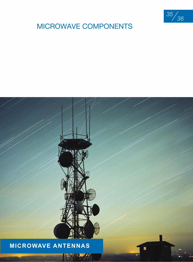
MIcrowAVE coMPonEntS
MICrowAve AnTennAS
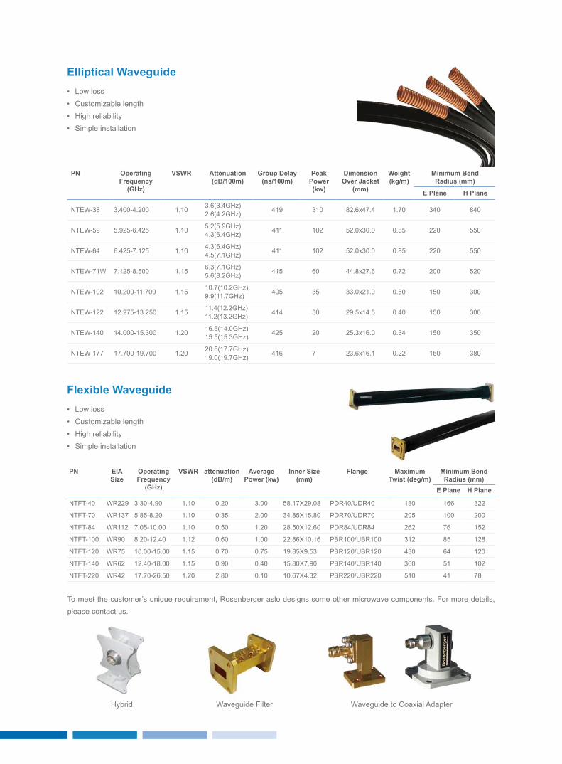
• Low loss• Customizable length • High reliability• Simple installation
elliptical waveguide
Pn operating Frequency
(GHz)
vSwr Attenuation(dB/100m)
Group Delay(ns/100m)
Peak Power(kw)
Dimension over Jacket
(mm)
weight(kg/m)
Minimum Bendradius (mm)
e Plane H Plane
NTEW-38 3.400-4.200 1.10 3.6(3.4GHz)2.6(4.2GHz) 419 310 82.6x47.4 1.70 340 840
NTEW-59 5.925-6.425 1.10 5.2(5.9GHz)4.3(6.4GHz) 411 102 52.0x30.0 0.85 220 550
NTEW-64 6.425-7.125 1.10 4.3(6.4GHz)4.5(7.1GHz) 411 102 52.0x30.0 0.85 220 550
NTEW-71W 7.125-8.500 1.15 6.3(7.1GHz)5.6(8.2GHz) 415 60 44.8x27.6 0.72 200 520
NTEW-102 10.200-11.700 1.15 10.7(10.2GHz)9.9(11.7GHz) 405 35 33.0x21.0 0.50 150 300
NTEW-122 12.275-13.250 1.15 11.4(12.2GHz)11.2(13.2GHz) 414 30 29.5x14.5 0.40 150 300
NTEW-140 14.000-15.300 1.20 16.5(14.0GHz)15.5(15.3GHz) 425 20 25.3x16.0 0.34 150 350
NTEW-177 17.700-19.700 1.20 20.5(17.7GHz)19.0(19.7GHz) 416 7 23.6x16.1 0.22 150 380
• Low loss• Customizable length• High reliability• Simple installation
Flexible waveguide
Pn eIASize
operating Frequency
(GHz)
vSwr attenuation(dB/m)
Average Power (kw)
Inner Size (mm)
Flange Maximum Twist (deg/m)
Minimum Bendradius (mm)
e Plane H Plane
NTFT-40 WR229 3.30-4.90 1.10 0.20 3.00 58.17X29.08 PDR40/UDR40 130 166 322
NTFT-70 WR137 5.85-8.20 1.10 0.35 2.00 34.85X15.80 PDR70/UDR70 205 100 200
NTFT-84 WR112 7.05-10.00 1.10 0.50 1.20 28.50X12.60 PDR84/UDR84 262 76 152
NTFT-100 WR90 8.20-12.40 1.12 0.60 1.00 22.86X10.16 PBR100/UBR100 312 85 128
NTFT-120 WR75 10.00-15.00 1.15 0.70 0.75 19.85X9.53 PBR120/UBR120 430 64 120
NTFT-140 WR62 12.40-18.00 1.15 0.90 0.40 15.80X7.90 PBR140/UBR140 360 51 102
NTFT-220 WR42 17.70-26.50 1.20 2.80 0.10 10.67X4.32 PBR220/UBR220 510 41 78
Waveguide FilterHybrid Waveguide to Coaxial Adapter
To meet the customer’s unique requirement, Rosenberger aslo designs some other microwave components. For more details, please contact us.

3837
roSEnbErgEr SErVIcE
MICrowAve AnTennAS
rosenberger offers professional services that improve network design, reliability, scalability and efficiency.
Our service core competences include:• Network optimization• Technical consultation• Customized product design• Installation & commissioning• Onsite training & supervision• System troubleshooting• After-sales services
In addition, we also offer professional training, technical support and workshops for distributors and agents. We are committed to offering exceptional services for our customers.
Rosenberger is much more than just a supplier – Rosenberger is a valued development partner and we will strive to meet new challenges in order to scale to new heights.

Mic
ro
wa
ve
an
te
nn
as
Microwave antennas
Rosenberger Asia Pacific Electronic Co., Ltd.
No.3, Anxiang Street, Block B, Tianzhu Airport Industrial Zone
Beijing, China 101300
Tel : (+86 10) 80481995
Fax : (+86 10) 80497052
Email: [email protected]
Rosenberger (Shanghai) Technology Co.,Ltd.
No. 303, Xinke Road, Qingpu Industrial Zone
Shanghai, China 201707
Tel : (+86 21) 69214567
Fax : (+86 21) 69212923
Rosenberger Asia Pacific Electronic Co., Ltd. Shanghai Division
B7, No. 509, Renqing Road, East Zone of Zhangjiang High-Tech Park
Shanghai, China 201201
Tel : (+86 21) 58995997
Fax : (+86 21) 58995594
Rosenberger Asia Pacific Electronic Co., Ltd. Dongguan Division
3rd Floor, Building E, Pingqian Industrial Park, Dongkeng Town
Dongguan, Guangdong Province, China
Tel : (+86 769) 82802098
Fax : (+86 769) 82802099
Rosenberger All rights reserved. 1st Edition, 2013
Please visit our website: www.RosenbergerAP.com
www.RosenbergerAP.com