
Introduction - King of Covers · HE T KING OF COVERS, INC. (860) 379-2427 Catalog of Parts
26
Transcript of Introduction - King of Covers · HE T KING OF COVERS, INC. (860) 379-2427 Catalog of Parts


THE KING OF COVERS, INC. (860) 379-2427
Table of Contents
Introduction 1
Close-Up Parts Diagram-Diagram 1 2
Full Truck Parts Diagram-Diagram 2 3
Figure Number/Part Number 4
Parts Listing with Pictures 5-8
Adjusting The Flow Control Valve 9
Electric Remote Pump Parts Diagram and List 10-11
Manual Pump Parts Diagram and List 12-13
Pump Repair and Maintenance 14-15
Cylinder Diagrams and Repair 16-17
Roller Tube Assembly and Repair 18-19
Changing The Tarp-while on the truck 20-21
Changing The Tarp-with roller tube off truck 21
Troubleshooting 22-23
© Copyright 2014 by The King of Covers, Inc.
154 Torrington Road, Winsted, Connecticut.
All rights reserved. No part of this material may be reproduced in any form
without the prior written permission of the copyright holder.

Congratulations! You are now the owner of a tried and true, Richard’s® Hydraulic
Covering System. Our systems have been covering loads since 1979, and we be-
lieve you won’t find a more durable system or better customer service anywhere.
We hope you are highly satisfied with your cover’s operation and enjoy many years
of hassle-free service. If you ever have questions or concerns, please call us; we
will be happy to assist you.
The system is controlled from the driver’s seat by a single switch. For optimum
durability, the cover should be “locked down” whenever the truck is in motion.
After the roller assembly reaches the end of its travel, either front or back, engage
the pump for an additional second to keep it locked down. When your system is
locked down, you should be able to see a slight downward bow in the arms. This
keeps the cover tight against the truck, preventing the tarp from unrolling, and re-
ducing wear from vibration as you travel.
The system benefits from regular inspection. The grease fittings located on each
flange casting (diagram 1, parts 39 and 57),should receive two shots of grease each
month. The hydraulic system is self-contained and shouldn’t need any additional
fluid unless you have done repair work or damaged the system. Should you need to
add fluid, we use Dexron II transmission fluid in our system. The oil level should
be about one inch below the fill hole when the roller assembly is at the front.
Never add fluid with the roller assembly at the back. The right and left sides of the
roller assembly should land on the cab shield at the same time. If they are more
than six inches apart in landing, see adjustment instructions for the flow control
valve. If your pump is operated by a manual valve body, occasionally check the
contact fingers and torsion spring on your pump handle assembly (page 12, parts 8
& 12) and replace them if they appear worn. If they fail, your pump may run con-
tinuously, and you risk burning out your motor (see troubleshooting on pages 22-
23). For pumps operated by a remote electric switch, no maintenance is necessary.
This gives you an overview of the proper use, and maintenance of your cover. For
more details on repair work, see the sections further on in this manual or bring your
truck in for servicing.
Thank you for choosing our cover. We’re confident you’ll be pleased!
Introduction
THE KING OF COVERS, INC. (860) 379-2427
1

THE KING OF COVERS, INC. (860) 379-2427
2
As viewed from passenger side
Close-Up Parts Diagram
Diagram 1
*se
e up
date
UPD
ATE
Mos
t cy
linde
rs in
stal
led
afte
r 01
/08
have
a s
teel
clev
is w
elde
d on
the
end
of
the
ram
ins
tead
of
a ca
st
alum
inum
cle
vis.
*
*

THE KING OF COVERS, INC. (860) 379-2427
Full Truck Part Diagram
Diagram 2
8
11
12
9
3
7
4
3
5 6
1 2 10
3

Diagram Numbers/Part Numbers
THE KING OF COVERS, INC. (860) 379-2427
Diagram 1
Diagram 2
Item # Part # Description 44, 45 Bolt, Washer
1 101/100 Driver’s Base/ Passenger’s Base 46 By Serial # Canvas Tarp
702 2 Pc. Roll Pin Set (old ) 47-52 Bolt, Washer, Lock Washer
705 Grade 8 Clevis Pin (new) 53 204 Roller Shaft
4 102 Lower Arm Casting 54 108 Spring Cone Casting
5 200 Lower Arm Tube 55 Screw
6, 7 402 Lower Arm Bolt & Lock Nut 56 205 Extra Heavy Spring
8 104 Mid Arm Casting 57 107 Driver Flange Casting
9, 11 404 Mid Arm Bolt & Lock Nut 58, 59 Bolt, Washer
12 405 Set Screw 60, 61 Washer, Cotter Pin
13 202 Upper Arm Tube
14, 16 406 Grade 8 Upper Arm Bolt
17 Set Screw Item # Part # Description
18 201 Cylinder 1 100/101 Passenger’s Base/Driver’s Base
19-21 700 Sm. Clevis , Washer, Cotter Pin 2 102 Lower Arm Casting
22 103 Cylinder Casting 3 111-1/111-2 Arch Castings - Thin/Thick
23-28 701 Lg. Clevis Pin, Washer, Cotter Pin 4 210 Rubber Back Stop Pad
29 105 Upper Arm Casting 5 112-1/112-2 Wedge Casting - Thin/Thick
30-35 403 Upper Arm Bolt 6 113 Backstop Casting
36, 37 Washer, Cotter Pin 7 209 Arch
38 203 Thrust Bearing 8 115 Roller Rest Casting
39 106 Passenger Flange Casting 9 PA Pivot Angle
40, 41 Bolt, Washer 10 110 Base Casting Spacer (not on all)
42 206 Roller Tube 11 211 Roller Rest Pad
43 109 Roller Ring Casting 12 PS Pivot Strap
3
Diagram 2
4

Catalog of Parts
THE KING OF COVERS, INC. (860) 379-2427
EZ 100-1 Small Base Casting-Passenger EZ 101-1 Small Base Casting-Driver EZ 100-2 Large Base Casting-Passenger EZ 101-2 Large Base Casting-Driver
Diagram 1 Item 1
Diagram 2 Item 1
EZ 102 Lower Arm Casting
Diagram 1 Item 4
Diagram 2 Item 2
EZ 104 Mid Arm Casting
Diagram 1 Item 8
Diagram 2 Not Identified
EZ 105 Upper Arm Casting
Diagram 1 Item 29
Diagram 2 Not Identified
Diagram 1 Item 22
Diagram 2 Not Identified
EZ 103 Cylinder Casting Replaced by steel clevis on newer systems
5
THE KING OF COVERS, INC. (860) 379-2427
Catalog of Parts
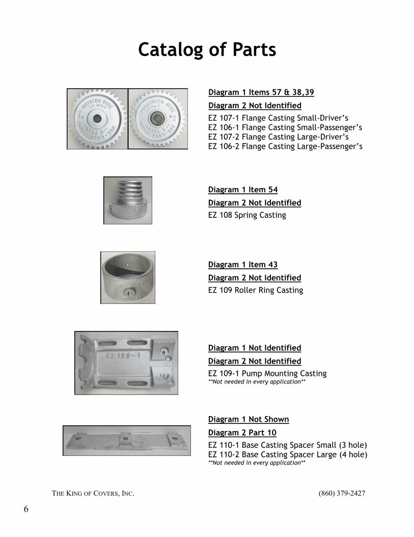
EZ 107-1 Flange Casting Small-Driver’s EZ 106-1 Flange Casting Small-Passenger’s EZ 107-2 Flange Casting Large-Driver’s EZ 106-2 Flange Casting Large-Passenger’s
Diagram 1 Items 57 & 38,39
Diagram 2 Not Identified
EZ 108 Spring Casting
Diagram 1 Item 54
Diagram 2 Not Identified
EZ 109 Roller Ring Casting
Diagram 1 Item 43
Diagram 2 Not Identified
EZ 109-1 Pump Mounting Casting **Not needed in every application**
Diagram 1 Not Identified
Diagram 2 Not Identified
Diagram 1 Not Shown
Diagram 2 Part 10
EZ 110-1 Base Casting Spacer Small (3 hole) EZ 110-2 Base Casting Spacer Large (4 hole) **Not needed in every application**
6

THE KING OF COVERS, INC. (860) 379-2427
Catalog of Parts
Diagram 1 Not Shown
Diagram 2 Not Shown
F20SK Flow Control Valve
EZ 111-1 Arch Casting-Thin EZ 111-2 Arch Casting-Thick
Diagram 1 Not Shown
Diagram 2 Item 3
EZ 115-1 Roller Rest-no rib EZ 115-2 Roller Rest-with rib EZ 115-3 Roller Rest-flat **Casting comes with pad attached. For rubber pad alone (figure 2 Part 13) item # EZ 211-1**
Diagram 1 Not Shown
Diagram 2 Item 8
EZ 112-1 Wedge Casting-Thin 1” EZ 112-2 Wedge Casting-Thick 1½”
Diagram 2 Item 5
Diagram 1 Not Shown
EZ 113 Back Stop Small-no rib EZ 113-2 Back Stop Large-with rib EZ 113-1 Back Stop Small-with rib **Casting comes with pad attached. For rub-ber pad alone (figure 2 Part 4) item # EZ 210 small or EZ 210-1 large**
Diagram 2 Item 6
Diagram 1 Not Shown
7
Catalog of Parts
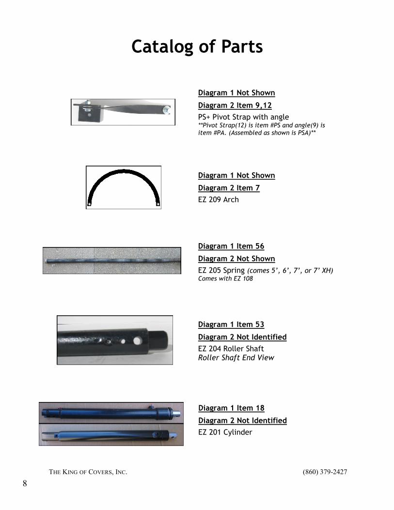
EZ 205 Spring (comes 5’, 6’, 7’, or 7’ XH) Comes with EZ 108
Diagram 2 Not Shown
Diagram 1 Item 56
Diagram 2 Not Identified
EZ 204 Roller Shaft Roller Shaft End View
Diagram 1 Item 53
EZ 201 Cylinder
Diagram 2 Not Identified
Diagram 1 Item 18
PS+ Pivot Strap with angle **Pivot Strap(12) is item #PS and angle(9) is item #PA. (Assembled as shown is PSA)**
Diagram 1 Not Shown
Diagram 2 Item 9,12
EZ 209 Arch
Diagram 1 Not Shown
Diagram 2 Item 7
THE KING OF COVERS, INC. (860) 379-2427
8
THE KING OF COVERS, INC. (860) 379-2427
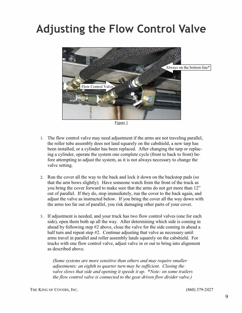
Adjusting the Flow Control Valve
Flow Control Valve
Always on the bottom line*
1. The flow control valve may need adjustment if the arms are not traveling parallel,
the roller tube assembly does not land squarely on the cabshield, a new tarp has
been installed, or a cylinder has been replaced. After changing the tarp or replac-
ing a cylinder, operate the system one complete cycle (front to back to front) be-
fore attempting to adjust the system, as it is not always necessary to change the
valve setting.
2. Run the cover all the way to the back and lock it down on the backstop pads (so
that the arm bows slightly). Have someone watch from the front of the truck as
you bring the cover forward to make sure that the arms do not get more than 12”
out of parallel. If they do, stop immediately, run the cover to the back again, and
adjust the valve as instructed below. If you bring the cover all the way down with
the arms too far out of parallel, you risk damaging other parts of your cover.
3. If adjustment is needed, and your truck has two flow control valves (one for each
side), open them both up all the way. After determining which side is coming in
ahead by following step #2 above, close the valve for the side coming in ahead a
half turn and repeat step #2. Continue adjusting that valve as necessary until
arms travel in parallel and roller assembly lands squarely on the cabshield. For
trucks with one flow control valve, adjust valve in or out to bring into alignment
as described above.
(Some systems are more sensitive than others and may require smaller
adjustments; an eighth to quarter turn may be sufficient. Closing the
valve slows that side and opening it speeds it up. *Note: on some trailers
the flow control valve is connected to the gear driven flow divider valve.)
Figure 1
9

THE KING OF COVERS, INC. (860) 379-2427
10
Electric Remote Pump Parts Breakdown
ADJUSTABLE RELIEF
VALVE (SEE NOTE
ON PAGE 15)
NEW COILS HAVE TWO YELLOW
WIRES. ONE FROM EACH GOES
TO RED/GREEN WIRES ON PART
#23 AS INDICATED. REMAINING
WIRE GOES TO GROUND ON
SOLENOID MOUNTING BRACKET.

THE KING OF COVERS, INC. (860) 379-2427
11
ITEM NO QTY PART NO DESCRIPTION
1 1 12789 BASE ASSY, M3534, MOD 3" MTR/BRKT
2 1 08111-D MOTOR, DC, 12V, 4.5", 1 TERM
3 1 12171-250 P ASSY, QM MDLR, DC, BRGS BLD RSV
4 4 07818 SCREW. S.H. CAP, 1/4-20 X 3
5 1 01209 TUBE, SUCTION, 90 DGR, 3/8 NPT
6 1 01134 FILTER, SCREEN M-SERIES SUCT.
7 1 13058 TUBE, RETURN, 90 DEG, 1/8NPT, M301
8 1 06910 RESV, 5X5X6, H/MT, M300, 2 3/4 CL
9 6 07703 SCREW, SELF-TAPPING, 10-24 3/8
10 2 00679-D CARTRIDGE, 3W/2P, #8, 3000PSI
11 1 07345-D VALVE, CHCK, CART, SIZE 8, DBL PILT
12 1 07781 WASHER, LOCK, 5/16
13 1 07773 SCREW, H.H. CAP, 5/16-18 X 1/2
14 1 01143 PLUG, RESEV, BREATHER-FILLER
15 1 01108 PLUG, SQUARE HEAD 1/4 NPT
16 1 02238 BRACKET, PUMP MT, M-SERIES
17 2 01988 WASHER, FLAT, 5/16", (ZINC PLATE)
18 2 07859 SCREW, HEX WASH HD, 5/16-18X5/8
19 1 07518 SWITCH, SOL, ACT MTR STRT, 12V
20 1 04776 STRAP, MTR-TOWER SOL CONNECTING
21 2 07587 SCREW, HEX, WSHR, SERRATED HD
22 1 03394 SWITCH, TOGGLE, W/JUMPER
23 1 13156DH112-018 CORD, HRNSS, 4 WIR, TGL SW, M3551
Electric Remote Pump Parts Item List
RELIEF VALVE ADJUSTMENT INSTRUCTIONS:
A. LOOSEN JAM NUT
B. ADJUST PRESSURE
1. TURN SCREW CLOCKWISE TO INCREASE PRESSURE
2. TURN SCREW COUNTER CLOCKWISE TO DECREASE PRESSURE
NOTE: OUTLET PORT (PRESSURE) FLOW MUST BE BLOCKED
TO MAKE RELIEF VALVE OPERATE WHILE ADJUSTING
C. TIGHTEN JAM NUT

THE KING OF COVERS, INC. (860) 379-2427
12
Manual Pump Parts Breakdown
SOLENOID POSTS MUST BE MAINTAINED INSULATED
Electric Remote Pump Bracket
Regular Pumps use EZ 109-1
THE KING OF COVERS, INC. (860) 379-2427
13
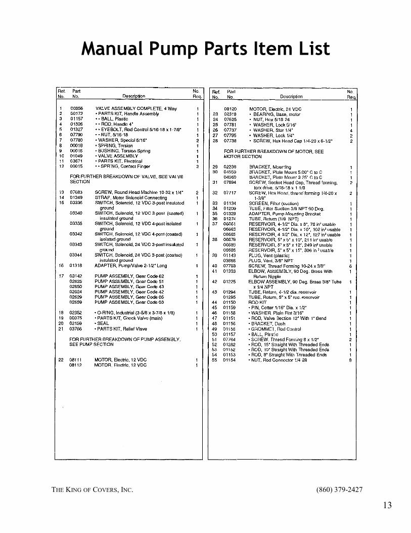
Manual Pump Parts Item List
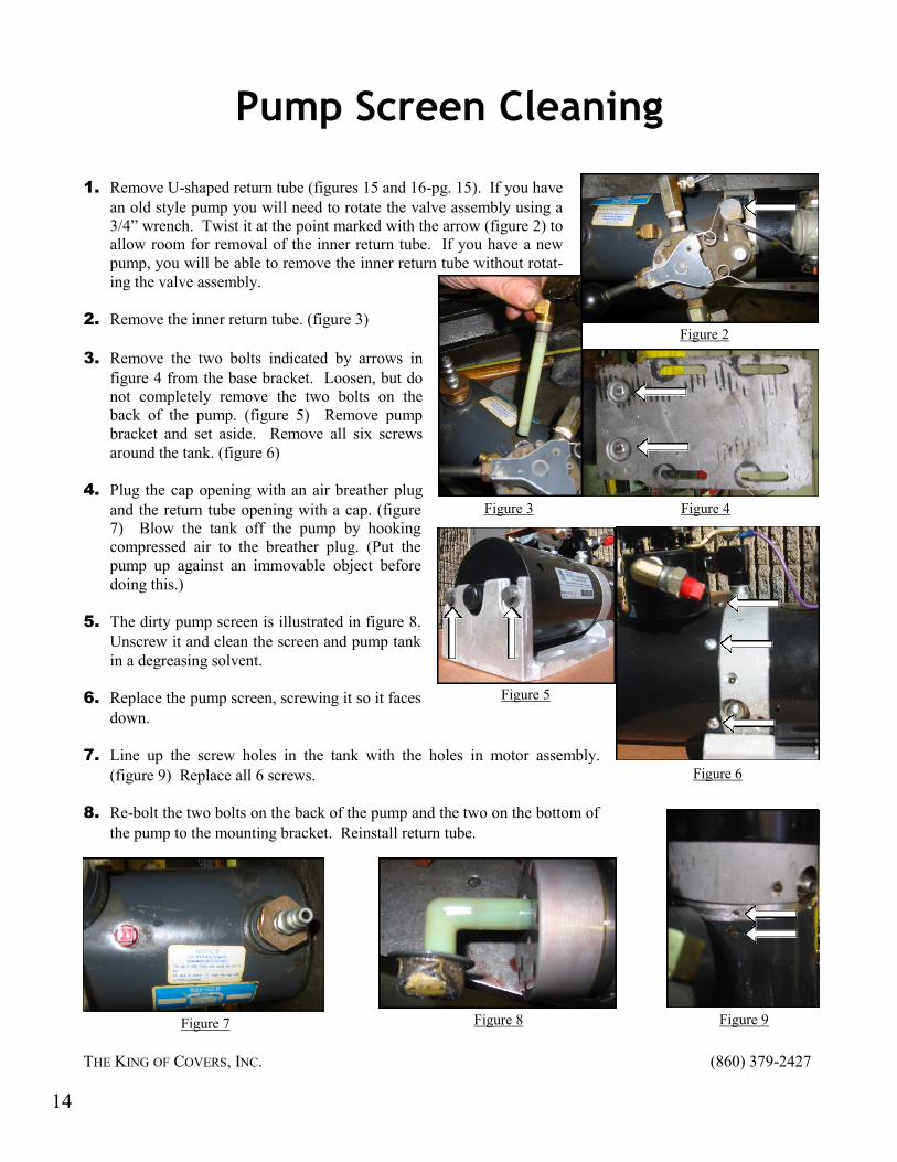
1. Remove U-shaped return tube (figures 15 and 16-pg. 15). If you have
an old style pump you will need to rotate the valve assembly using a
3/4” wrench. Twist it at the point marked with the arrow (figure 2) to
allow room for removal of the inner return tube. If you have a new
pump, you will be able to remove the inner return tube without rotat-
ing the valve assembly.
2. Remove the inner return tube. (figure 3)
3. Remove the two bolts indicated by arrows in
figure 4 from the base bracket. Loosen, but do
not completely remove the two bolts on the
back of the pump. (figure 5) Remove pump
bracket and set aside. Remove all six screws
around the tank. (figure 6)
4. Plug the cap opening with an air breather plug
and the return tube opening with a cap. (figure
7) Blow the tank off the pump by hooking
compressed air to the breather plug. (Put the
pump up against an immovable object before
doing this.)
5. The dirty pump screen is illustrated in figure 8.
Unscrew it and clean the screen and pump tank
in a degreasing solvent.
6. Replace the pump screen, screwing it so it faces
down.
7. Line up the screw holes in the tank with the holes in motor assembly.
(figure 9) Replace all 6 screws.
8. Re-bolt the two bolts on the back of the pump and the two on the bottom of
the pump to the mounting bracket. Reinstall return tube.
THE KING OF COVERS, INC. (860) 379-2427
Pump Screen Cleaning
Figure 2
Figure 3 Figure 4
Figure 5
Figure 6
Figure 7 Figure 8 Figure 9
14
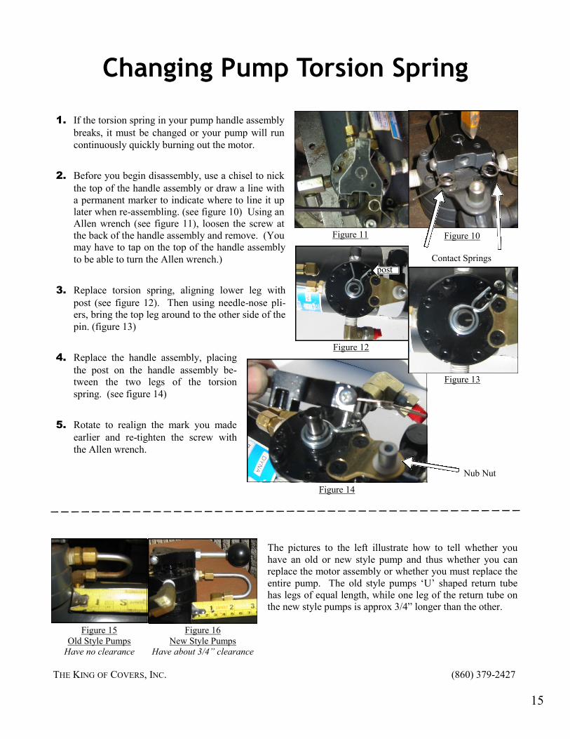
The pictures to the left illustrate how to tell whether you
have an old or new style pump and thus whether you can
replace the motor assembly or whether you must replace the
entire pump. The old style pumps ‘U’ shaped return tube
has legs of equal length, while one leg of the return tube on
the new style pumps is approx 3/4” longer than the other.
1. If the torsion spring in your pump handle assembly
breaks, it must be changed or your pump will run
continuously quickly burning out the motor.
2. Before you begin disassembly, use a chisel to nick
the top of the handle assembly or draw a line with
a permanent marker to indicate where to line it up
later when re-assembling. (see figure 10) Using an
Allen wrench (see figure 11), loosen the screw at
the back of the handle assembly and remove. (You
may have to tap on the top of the handle assembly
to be able to turn the Allen wrench.)
3. Replace torsion spring, aligning lower leg with
post (see figure 12). Then using needle-nose pli-
ers, bring the top leg around to the other side of the
pin. (figure 13)
4. Replace the handle assembly, placing
the post on the handle assembly be-
tween the two legs of the torsion
spring. (see figure 14)
5. Rotate to realign the mark you made
earlier and re-tighten the screw with
the Allen wrench.
Changing Pump Torsion Spring
Figure 10 Figure 11
Figure 13
Figure 12
post
Figure 14
Figure 16
New Style Pumps
Have about 3/4” clearance
Figure 15
Old Style Pumps
Have no clearance
Contact Springs
Nub Nut
THE KING OF COVERS, INC. (860) 379-2427
15

A-Style Cylinder-Figure A
B-Style PolyPak Cylinder-Figure B
5
4 2
3
7 10
8
9
6 8
THE KING OF COVERS, INC. (860) 379-2427
Cylinder Diagrams
16
5
4 2
3
10
7 9
8 6
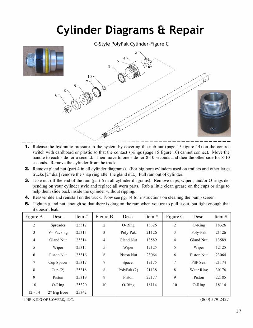
Cylinder Diagrams & Repair
1. Release the hydraulic pressure in the system by covering the nub-nut (page 15 figure 14) on the control
switch with cardboard or plastic so that the contact springs (page 15 figure 10) cannot connect. Move the
handle to each side for a second. Then move to one side for 8-10 seconds and then the other side for 8-10
seconds. Remove the cylinder from the truck.
2. Remove gland nut (part 4 in all cylinder diagrams). (For big bore cylinders used on trailers and other large
trucks [2” dia.] remove the snap ring after the gland nut.) Pull ram out of cylinder.
3. Take nut off the end of the ram (part 6 in all cylinder diagrams). Remove cups, wipers, and/or O-rings de-
pending on your cylinder style and replace all worn parts. Rub a little clean grease on the cups or rings to
help them slide back inside the cylinder without ripping.
4. Reassemble and reinstall on the truck. Now see pg. 14 for instructions on cleaning the pump screen.
5. Tighten gland nut, enough so that there is drag on the ram when you try to pull it out, but tight enough that
it doesn’t leak.
C-Style PolyPak Cylinder-Figure C
Figure A Item # Figure B Desc. Figure C Desc. Desc. Item # Item #
2 25312 2 O-Ring 2 O-Ring Spreader 18326 18326
3 25313 3 Poly-Pak 3 Poly-Pak V– Packing 21126 21126
4 25314 4 Gland Nut 4 Gland Nut Gland Nut 13589 13589
5 25315 5 Wiper 5 Wiper Wiper 12125 12125
6 25316 6 Piston Nut 6 Piston Nut Piston Nut 23064 23064
7 25317 7 Spacer 7 PSP Seal Cup Spacer 19175 21174
8 25318 8 PolyPak (2) 8 Wear Ring Cup (2) 21138 30176
9 25319 9 Piston 9 Piston Piston 22177 22185
10 25320 10 O-Ring 10 O-Ring O-Ring 18114 18114
12 - 14 25342 2” Big Bore
THE KING OF COVERS, INC. (860) 379-2427
17
Roller Tube Assembly and Repair
REMOVING THE ROLLER TUBE ASSEMBLY FROM THE TRUCK NEVER EXTEND THE COVER TO THE BACK OF THE TRUCK WHEN DISASSEMBLING AS THIS WINDS THE SPRING TIGHTER. ASSEMBLY AND DISASSEMBLY OF THE ROLLER ASSEMBLY MUST BE MADE FROM THE FRONT ONLY.
Begin by putting some pressure in the system to lift the roller assembly 6-10” off the cab. This procedure should
be accomplished with one person on each side of the truck; however, if you are repairing the roller tube assem-
bly by yourself, tie the arms together to prevent it from falling out of the upper arm castings. (figure 20 page 20)
Remove top nut and bolt from the upper arm casting(29) on one side, then place a 3/4” offset box end wrench
over the end of the roller shaft (53) on the other side and remove the bolt (figure 25 page 21).
MAKE SURE YOU HAVE A GOOD GRIP ON THE WRENCH TO PREVENT THE SPRING TENSION ON THE ROLLER SHAFT FROM CAUSING THE WRENCH TO SPIN AROUND 6 OR 7 TIMES CAUSING SERIOUS IN-
JURY. MAINTAIN A FIRM GRIP ON THE WRENCH AND UNWIND SLOWLY, KEEPING YOUR BODY AWAY FROM THE ROTATION OF THE WRENCH.
If changing the canvas at the same time, remove 8 bolts holding the canvas to the pivot straps. (Note: the outside
bolts have nuts on the back, remove the nuts first) Otherwise, leave the front of the tarp attached to pivot straps,
unroll the tarp from the roller tube, unbolt from the roller tube, and leave the tarp in truck bed.
Carefully slide each upper arm casting off the roller tube shaft, and lower the arm
gently until it stops. Remove roller tube assembly from cab shield. If changing
tarp, unroll, and unbolt old tarp from roller tube.
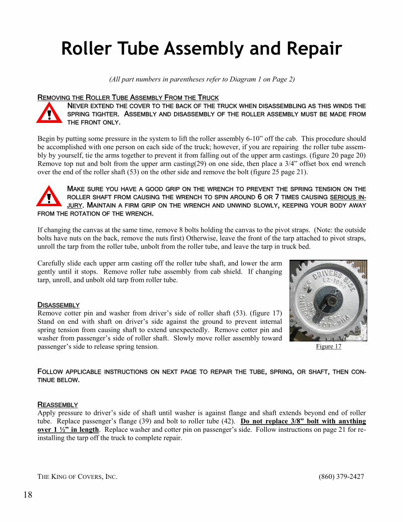
DISASSEMBLY Remove cotter pin and washer from driver’s side of roller shaft (53). (figure 17)
Stand on end with shaft on driver’s side against the ground to prevent internal
spring tension from causing shaft to extend unexpectedly. Remove cotter pin and
washer from passenger’s side of roller shaft. Slowly move roller assembly toward
passenger’s side to release spring tension.
FOLLOW APPLICABLE INSTRUCTIONS ON NEXT PAGE TO REPAIR THE TUBE, SPRING, OR SHAFT, THEN CON-
TINUE BELOW.
REASSEMBLY Apply pressure to driver’s side of shaft until washer is against flange and shaft extends beyond end of roller
tube. Replace passenger’s flange (39) and bolt to roller tube (42). Do not replace 3/8” bolt with anything
over 1 ½” in length. Replace washer and cotter pin on passenger’s side. Follow instructions on page 21 for re-
installing the tarp off the truck to complete repair.
Figure 17
THE KING OF COVERS, INC. (860) 379-2427
(All part numbers in parentheses refer to Diagram 1 on Page 2)
18

Roller Tube Assembly and Repair
REPLACING ROLLER TUBE (42) Remove three bolts from the passenger side flange casting (39) and pull flange casting from tube. Remove three
bolts from the driver side flange casting (57) and slide broken roller tube (42) off shaft. If reusing roller rings
(43) remove from broken tube and install on new tube. Slide new tube onto shaft and reattach driver’s flange
casting with three bolts. Do not replace 3/8” bolt with anything over 1 ½” in length.
REPLACING SPRING (56) Remove three bolts from passenger’s (39) flange casting and pull flange casting from tube. Remove three bolts
from driver’s (57) flange casting and slide roller tube (42) off shaft. Loosen two set screws (55) and slide spring
and driver’s flange (57) from shaft (53). Place driver’s flange in a vice and, using a spanner wrench, remove
broken spring from flange. Note: this is a left handed thread. Screw new spring on driver’s flange using a pipe
wrench. Slide shaft inside of spring. If marks from set screws are visible, slide shaft to the same position and
retighten screws. If not, replace washer and cotter pin on driver’s end of shaft. Using measurement from Chart
1, move driver’s flange required distance from washer (figure 19). Tighten set screws. Slide roller tube over
spring and shaft and attach using three bolts to driver’s flange. Do not replace 3/8” bolt with anything over 1 ½”
in length.
REPLACING/REPAIRING SHAFT (53) Remove three bolts from passenger’s (39) flange casting and pull flange casting from tube. Remove three bolts
from driver’s (57) flange casting and slide roller tube (42) off shaft. Loosen two set screws (55) and slide spring
and driver’s flange (57) from bent/broken shaft (53). Most bent shafts can be straightened without heat using a
manual press. After either straightening your bent shaft or purchasing a new one, slide shaft inside spring. If
reusing straightened shaft and marks from set screws on spring are visible, slide shaft to the same position and
retighten screws. If not, replace washer and cotter pin on driver’s end of shaft. Using measurement from Chart
1, move driver’s flange required distance from washer (figure 19). Tighten set screws (55). Slide roller tube
over spring and shaft and attach using three bolts to driver’s flange. Do not replace 3/8” bolt with anything over
1 ½” in length.
Spring Length Measurement X
5’ 6”
6’ 7”
7’ 8”
Chart 1
X”
Figure 18
For cotter pin
For upper arm bolt
Figure 19
THE KING OF COVERS, INC. (860) 379-2427
19

NEVER EXTEND THE COVER TO THE BACK OF THE TRUCK WHEN DISASSEMBLING AS THIS WINDS THE SPRING TIGHTER. ASSEMBLY AND DISASSEMBLY OF THE ROLLER ASSEMBLY MUST BE MADE FROM THE FRONT ONLY.
Begin by putting some pressure in the system to lift the
roller assembly 6-10” off the cab. If you are changing the
tarp by yourself, tie the arms together to prevent the roller
tube assembly from falling out of the upper arm castings.
(figure 20) Remove top nut and bolt from the upper arm
casting on one side, then place a 3/4” offset box end wrench
over the end of the roller shaft on the other side and remove
the bolt.
MAKE SURE YOU HAVE A GOOD GRIP ON THE WRENCH TO PREVENT THE SPRING TENSION ON
THE ROLLER SHAFT FROM CAUSING THE WRENCH TO SPIN AROUND 6 OR 7 TIMES CAUSING SERIOUS INJURY. MAINTAIN A FIRM GRIP ON THE WRENCH AND UNWIND SLOWLY, KEEPING YOUR BODY AWAY FROM THE ROTA-
TION OF THE WRENCH.
Remove 8 bolts holding the old tarp to the pivot straps. (Note: the
outside bolts have nuts on the back, remove the nuts first) Unroll the
tarp and unbolt from the roller tube.
New tarp: Lay the tarp in the bed with the white
tag facing up in the back on the driver’s side.
(figure 21) (except rolloffs—place with tag facing
down) Place the back of the tarp over the top of
the roller tube, hem side up. (figures 22, 23) Place
the flat washer and then the lock washer on top of
the grommet before bolting. (figure 24) Use a zip-
tie for the center grommet.
Using the 3/4” offset box end wrench, roll the tarp around the tube, turning towards the front of the truck. (In the
direction of the arrows on the flange casting - figure 25, page 23)
Changing the Tarp
Figure 20
Tag facing up in back driver’s side corner
Figure 21
Figure 22 Figure 23
Figure 24
Without removing the roller tube from the truck
Truck Body Length Number of Turns
15’ and under 6 1/2
16-17’ 7 1/2
18-19’ 7
20’ and Trailers 7 1/2
Roll-Off Trucks 8
Roll-Off HD Spring 3
Chart 2
THE KING OF COVERS, INC. (860) 379-2427
20

With the pivot strap behind the tarp (figure 26), bolt the front of the tarp to the
pivot straps with a flat washer and lock washer as shown in Figure 24 page 20.
(Note: the outside bolts have nuts on the back.)
Turning the flange by hand, remove all slack from tarp. Using the 3/4” offset
box end wrench, tension the spring using the appropriate number of turns from
Chart 2. Make sure you rotate the wrench in the direction indicated by the ar-
row on the flange casting.
MAINTAIN A GOOD GRIP ON THE WRENCH TO PREVENT THE SPRING TENSION ON THE ROLLER SHAFT FROM CAUSING THE WRENCH TO
SPIN AROUND 6 OR 7 TIMES CAUSING SERIOUS INJURY. MAINTAIN A FIRM GRIP ON THE WRENCH AND WIND SLOWLY, KEEPING YOUR BODY AWAY FROM THE ROTATION OF THE WRENCH.
After achieving the proper tension, while still holding the wrench firmly, insert
the bolts through the upper arm casting and roller shaft. Remove wrench and
install and tighten the nuts on the bolts. Run the cover out and in once to make
sure the roller tube lands squarely on the cab shield. If it does not, see page 11
on adjusting your flow control valve.
Changing the Tarp-off the Truck
Lay the roller tube as illustrated in figures 27 and 28 with the nice side of the tarp face-up. Wrap it under the
roller tube and over the top. Secure the center grommet with a zip tie and bolt the other four grommets down
with washers and lock washers (see figure 24, page 20).
Have two people grasp the front corners of
the tarp and pull it toward them slowly. The
roller tube will roll up the tarp as it rolls to-
ward them. (see figure 29) Have each person
place their foot on the flange gear to keep the
roller tube from unrolling and pull the tarp
tight around the tube. Place the assembly on
the truck (make sure driver’s flange is on
driver’s side) with
the shaft through the
center of the upper
arm castings. (See
top of page for re-
mainder of instruc-
tions.)
Changing the Tarp
Figure 25
Figure 26
FRONT
BACK
PA
SS
EN
GE
R
DR
IVE
R
Figure 28
Figure 27 Figure 29 (this canvas has flaps)
THE KING OF COVERS, INC. (860) 379-2427
21

Troubleshooting
Pumps
Broken contact spring
A broken contact spring will prevent the pump from operating. To replace a contact spring, remove
screw and replace broken part with a new one making sure the coil spring faces the outside of the
pump.
Bad ground
Most problems with pumps are ground related problems. Using a 12 volt multi-meter, clip the posi-
tive on the multi-meter to the battery positive at the solenoid. Clip the ground of the multi-meter to
a good ground on the pump (such as the aluminum block in the center of the pump). Operate the
pump; if the multi-meter drops below 12V, you have a bad ground. Using battery cable, connect
the battery ground to the hold down bolt on the pump under the floor of the cab.
Bad solenoid
Using a 12 volt multi-meter, clip the positive on the multi-meter to the copper strap on the back
side of the solenoid that goes to the motor. Operate pump; you should get 12V. If you do not, you
have a bad solenoid.
Bad motor
If you have tried all of the above and you get 12V, but the pump still doesn’t work, you have a bad
motor.
Cover moves slowly, only in one direction, or not at all
Worn cylinder packings
Raise the roller assembly about one foot off the cab shield. If it settles back down on its own, the
cylinder packings are likely failing and need to be replaced. Refer to page 17 for instructions on
repacking a cylinder.
A slow leak somewhere in the system would have a similar result but leaking oil should be seen if a
leak exists. If no oil is visible, see leaking crossover lines below as oil may be trapped inside body
rails.
Broken roller tube, bent roller shaft or improper spring tension
Failure of the roller tube to work smoothly usually indicates a broken roller tube, bent roller shaft
or improper spring tension as a result of slipping or breaking. If the arms are moving properly but
the canvas will not roll up when moving from the back to the front, the spring inside the roller as-
sembly has most likely lost its pre-set tension as a result of breaking, being put on backwards or
slipping off its internal mountings. Refer to pages 18-19 for instructions on repairing the roller as-
sembly.
THE KING OF COVERS, INC. (860) 379-2427
22
Troubleshooting
THE KING OF COVERS, INC. (860) 379-2427
Badly worn tarp or excessive build up of asphalt on tarp
Replace canvas. Refer to pages 20-21 for replacing the tarp.
Leaking crossover line
If the body is heated and the cover has been on the truck for several years the crossover lines may
have a hole in them. Replace both crossover lines
Plugged pump screen
If the pump makes a high pitched whining sound, the screen in the tank is most likely plugged and
needs to be cleaned. Refer to page 14 for instructions on cleaning the pump screen.
Flange Casting caught
Under rare circumstances, the teeth on the flange casting may get stuck either in the backstop pad
or on the bolt heads that hold down the backstop pad .
Tarp Rolls Up Unevenly
Worn tarp
The roller assembly is designed to land evenly on the cab shield and should not be allowed to be
more than six to eight inches out of alignment. A worn tarp, especially with one or more tears on an
edge, is the primary cause of trouble. If the tarp is severely worn, no amount of adjusting will cor-
rect an uneven operation; the tarp will need to be replaced. Refer to pages 20-21 for replacing the
tarp.
Heavy build up of asphalt on tarp
Refer to pages 20-21 for replacing the tarp.
Broken roller tube
Examine roller tube, especially under the roller rings and make sure it isn’t broken. Refer to pages
18-19 for repairing the roller assembly.
Bent arms
Either straighten or replace bent arms.
Tarp not centered on roller assembly
Operating in high wind can push the tarp to one side of the roller assembly. If the tarp is not cen-
tered on the roller assembly when it is at the back of the truck, manually unroll the tarp the rest of
the way, re-center it on the tube and then allow it to re-roll on the tube.
Tarp may have stretched
If the tarp is in good shape and nothing is bent or broken, the tarp may have stretched. This can be
fixed by adjusting the knob on the flow control valve. Turning the valve stem in will slow the
driver’s side arm down as it moves to the front. If the cylinder is style A (pg. 16) with a gland nut at
the top end, tightening the nut a quarter to a half turn will slow that side down.
23