
Introduction Harmonic filter design for EMT study ... · Harmonic impact study Filter design EMT...
20
Introduction Harmonic impact study Filter design EMT study Conclusion Harmonic filter design for electrified railways DIgSILENT USER GROUP Sydney — 5 September 2013 M Jansen, S Hagaman, T George
-
Upload
nguyennhan -
Category
Documents
-
view
222 -
download
1
Transcript of Introduction Harmonic filter design for EMT study ... · Harmonic impact study Filter design EMT...

Introduction
Harmonicimpact study
Filter design
EMT study
Conclusion
Harmonic filter design forelectrified railwaysDIgSILENT USER GROUP
Sydney — 5 September 2013
M Jansen, S Hagaman, T George

Introduction
Harmonicimpact study
Filter design
EMT study
Conclusion
Introduction
I Railway electrification projectI Adds significant unbalanced non-linear load to the gridI PowerFactory used for
I Harmonic emission/complianceI Filter design/ratingI EMT reviewI Protection design
Introduction
Harmonicimpact study
Filter design
EMT study
Conclusion
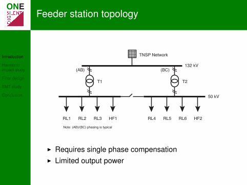
Feeder station topology
TNSP Network
132 kV
RL1 RL2 RL3 HF1 RL4 RL5 RL6 HF2
50 kV
(AB) (BC)
T1 T2
Note: (AB)/(BC) phasing is typical
I Requires single phase compensationI Limited output power

Introduction
Harmonicimpact study
Filter design
EMT study
Conclusion
Emission limits
Emis
sion
lim
it (%
of V
1)
0
0.5
1.0
1.5
Harmonic orderTHD 7 13 19 25 31 37 43 49

Introduction
Harmonicimpact study
Filter design
EMT study
Conclusion
Range of network conditions
Net
wor
k im
peda
nce
(Ω)
10
100
1000
Frequency (× 50 Hz)0 5 10 15 20 25 30 35 40 45 50

Introduction
Harmonicimpact study
Filter design
EMT study
Conclusion
Current spectra
MeasuredExpandedUsed
Cur
rent
em
issi
on (%
of V
1)
0.001
0.01
0.1
1
10
Harmonic orderTHD 7 13 19 25 31 37 43 49

Introduction
Harmonicimpact study
Filter design
EMT study
Conclusion
Voltage distortion without filters
PoC
vol
tage
dis
torti
on (%
of V
1)
0.001
0.01
0.1
1
10
Harmonic orderTHD 7 13 19 25 31 37 43 49

Introduction
Harmonicimpact study
Filter design
EMT study
Conclusion
Filter configuration
Shunt Third Fifth Ninth
Phase A
Phase B
From 50 kV switchroom

Introduction
Harmonicimpact study
Filter design
EMT study
Conclusion
Voltage distortion with filters
PoC
vol
tage
dis
torti
on (%
of V
1)
0.001
0.01
0.1
1
Harmonic orderTHD 7 13 19 25 31 37 43 49
Introduction
Harmonicimpact study
Filter design
EMT study
Conclusion
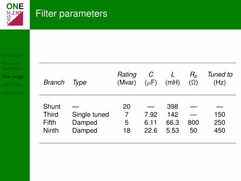
Filter parameters
Rating C L Rp Tuned toBranch Type (Mvar) (µF) (mH) (Ω) (Hz)
Shunt — 20 — 398 — —Third Single tuned 7 7.92 142 — 150Fifth Damped 5 6.11 66.3 800 250Ninth Damped 18 22.6 5.53 50 450

Introduction
Harmonicimpact study
Filter design
EMT study
Conclusion
Component ratings
Capacitor VN Reactor IRMS Resistor PR(kV) (A) (kW)
Third 78.2 178.78 –Fifth 64.8 117.21 16Ninth 61.0 414.45 80

Introduction
Harmonicimpact study
Filter design
EMT study
Conclusion
Electromagnetic study
I Design for electromagnetic transient (EMT) phenomena
I Peak voltage across capacitor banksI Peak currentsI Protection setting stability
I Studies for switching transients and lightning surgesI Specification of mitigation measures

Introduction
Harmonicimpact study
Filter design
EMT study
Conclusion
Model augmentation for EMT study
TNSP Network
132 kV
RL1
RL2
RL3 HF1 RL4 RL5
RL6
HF2
50 kV
T1 T2
Stray capacitance
Surge arrester

Introduction
Harmonicimpact study
Filter design
EMT study
Conclusion
PowerFactory simulation
I Operational scenarios to define different switchingarrangements
I 1 or 2 transformers onlineI 1 or 2 filters onlineI Several different track feeder arrangementsI Lightning strike points
I Study cases for each switching/lightning caseI Analysis of different point on wave switchingI DPL scripts to automate study cases, print plots and
analyse waveforms

Introduction
Harmonicimpact study
Filter design
EMT study
Conclusion
Switching study
VC3 VC5 VC9
Cap
acito
r vol
tage
(kV)
0
200
Time (s)0.02 0.04 0.06 0.08 0.10
I3 I5 I9
Bran
ch c
urre
nt (k
A)
−1
0
1
Time (s)0.02 0.04 0.06 0.08 0.10

Introduction
Harmonicimpact study
Filter design
EMT study
Conclusion
Mitigation measures
I Switching transientI Surge arresters specified across the 3rd tuned branch
capacitor bank (approaching IEC 60871-1 peak limit)I Overcurrent protection graded to avoid spurious trips on
filter energisationI Lightning surge
I Surge arresters specified for the filter busbars

Introduction
Harmonicimpact study
Filter design
EMT study
Conclusion
Capacitor bank voltages with surge arresters
175.4 kV
-205.9 kV
IEC 60871 voltage withstand limit
V C3 (
kV)
−200
0
200
Time (s)0.005 0.010 0.015 0.020

Introduction
Harmonicimpact study
Filter design
EMT study
Conclusion
Surge arrester current — PoW switching
PoW time 6 ms, Ipeak = -380 A
I MO
V (k
A)
−0.4
−0.2
0
Time (s)0.005 0.010 0.015 0.020 0.025 0.030

Introduction
Harmonicimpact study
Filter design
EMT study
Conclusion
Surge arrester current — Lightning
Cur
rent
(kA)
0
10
Time (ms)−0.1 0 0.1 0.2
Ener
gy (k
J)
0
20
Time (ms)−0.1 0 0.1 0.2

Introduction
Harmonicimpact study
Filter design
EMT study
Conclusion
Conclusion
Thank you for your time
Questions?


