
INTRODUCTION - df_media.s3.amazonaws.com · the special operating characteristics of sidecar outfit...
103
-
Upload
vuongduong -
Category
Documents
-
view
214 -
download
0
Transcript of INTRODUCTION - df_media.s3.amazonaws.com · the special operating characteristics of sidecar outfit...

Intentionally left blank
INTRODUCTION
Welcome to the URAL Motorcycling Family! Your Ural has been built by the Irbit Motorcycle Factory in Russia and distributed by Irbit Motorworks of America, the United States affiliate of the Irbit Motorcycle Factory. This Ural motorcycle conforms to all applicable US Federal Motor Vehicle Safety Standards and US Environmental Protection Agency regulations effective on the date of manufacture. This manual covers the Gear-Up, Patrol, and cT model and has been prepared to acquaint you with the operation, care and maintenance of your motorcycle and to provide you with important safety information. Follow these instructions carefully for maximum motorcycle performance and for your personal motorcycling safety and pleasure. It is critical that a beginning sidecar driver becomes thoroughly familiar with the special operating characteristics of sidecar outfit before venturing out on the busy roads. Your Owner’s Manual contains instructions for operation, maintenance and minor repairs. Major repairs require the attention of a skilled mechanic and the use of special tools and equipment. Your Authorized IMWA Ural Dealer has the facilities, experience and genuine Ural parts necessary to properly render this valuable service. Any suggestions or comments are welcome! Happy Uraling!
IMPORTANT SAFTEY INFORMATION
WE STRORLY SUGGEST THAT YOU READ THIS MANUAL COMPLETELY PRIOR TO RIDING
YOUR NEW URAL MOTORCYLE. THIS MANUAL CONTAINS INFORMATION AND ADVICE
THAT WILL HELP YOU PROPERLY OPERATE AND MAINTAIN YOUR MOTORCYCLE. PLEASE
PAY SPECIAL ATTENTION TO NOTICES IN THIS MANUAL MARKED AS FOLLOWS:
CAUTION
INDICATES POSSIBILITY OF EQUIPMENT FAILURE THAT MAY RESULT IN YOUR
MOTORCYLE BE UNSAFE TO OPERATE IF INSTRUCTIONS ARE NOT FOLLOWED
WARNING
INDICATES A VERY STRONG POSSIBLILITY OF INJURY TO YOURSELF AND OTHERS OR
LOSS OF LIFE IF INSTRUCTIONS ARE NOT FOLLOWED
NOTE
PROVIDES HELPFUL INFORMATION AND TIPS
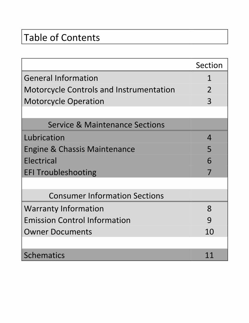
Table of Contents
Section
General Information 1
Motorcycle Controls and Instrumentation 2
Motorcycle Operation 3
Service & Maintenance Sections
Lubrication 4
Engine & Chassis Maintenance 5
Electrical 6
EFI Troubleshooting 7
Consumer Information Sections
Warranty Information 8
Emission Control Information 9
Owner Documents 10
Schematics 11
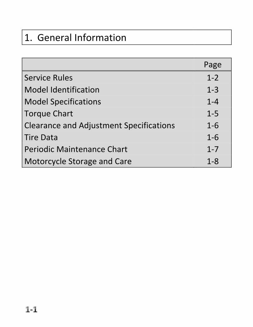
1. General Information
Page
Service Rules 1-2
Model Identification 1-3
Model Specifications 1-4
Torque Chart 1-5
Clearance and Adjustment Specifications 1-6
Tire Data 1-6
Periodic Maintenance Chart 1-7
Motorcycle Storage and Care 1-8
SERVICE RULES
1. Always wear proper safety equipment including but not limited to safety glasses
and gloves.
2. Allow your motorcycle to cool down completely prior to servicing to avoid getting
burned.
3. Always use genuine Ural or Ural recommended parts, fluids and components
when servicing your motorcycle. Parts that do not meet these requirements may
result in damage.
4. Follow the service procedures as outlined in this manual.
5. Always follow the torque specifications when tightening nuts and bolts.
6. Clean all parts with non-flammable solvents prior to reassembly after servicing.
7. Always replace seals, O-rings, gaskets and cotter pins when reassembling.
8. If you remove self-locking nuts they should always be replaced with new ones.
9. Be responsible with solvents, cleaners and waste oils. Always dispose of them in
accordance with your local regulations.
WARNING
IF THE ENGINE MUST BE RUNNING TO PREFORM A PARTICULAR SERVICE
PROCEEDURE BE SURE YOU ARE IN A WELL VENTALATED AREA. EXHAUST
CONTAINS CARBON MONOXIDE GAS.
WARNING
GASOLINE IS VERY FLAMMABLE AND CAN BE EXPLOSIVE UNDER CERTAIN CONDITIONS.
IT IS ALSO VERY HARMFUL TO THE SKIN AND EYES. DO NOT SMOKE OR ALLOW SPARKS
IN OR NEAR YOUR WORK AREA.
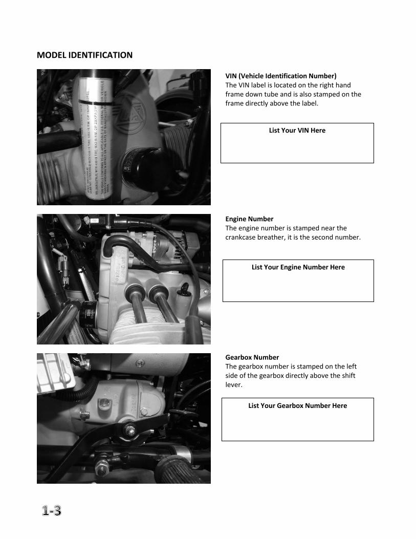
MODEL IDENTIFICATION
VIN (Vehicle Identification Number) The VIN label is located on the right hand frame down tube and is also stamped on the frame directly above the label.
List Your VIN Here
Engine Number The engine number is stamped near the crankcase breather, it is the second number.
List Your Engine Number Here
Gearbox Number The gearbox number is stamped on the left side of the gearbox directly above the shift lever.
List Your Gearbox Number Here
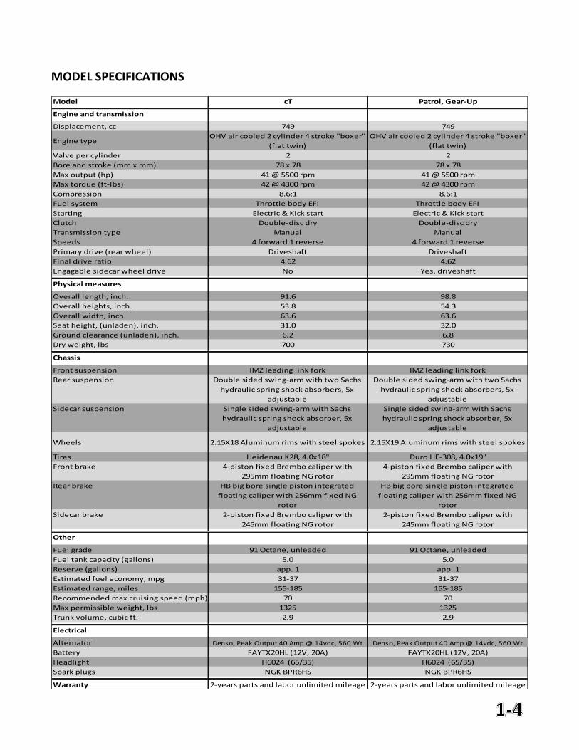
MODEL SPECIFICATIONS
Model cT Patrol, Gear-Up
Engine and transmission
Displacement, cc 749 749
Engine typeOHV air cooled 2 cylinder 4 stroke "boxer"
(flat twin)
OHV air cooled 2 cylinder 4 stroke "boxer"
(flat twin)
Valve per cylinder 2 2
Bore and stroke (mm x mm) 78 x 78 78 x 78
Max output (hp) 41 @ 5500 rpm 41 @ 5500 rpm
Max torque (ft-lbs) 42 @ 4300 rpm 42 @ 4300 rpm
Compression 8.6:1 8.6:1
Fuel system Throttle body EFI Throttle body EFI
Starting Electric & Kick start Electric & Kick start
Clutch Double-disc dry Double-disc dry
Transmission type Manual Manual
Speeds 4 forward 1 reverse 4 forward 1 reverse
Primary drive (rear wheel) Driveshaft Driveshaft
Final drive ratio 4.62 4.62
Engagable sidecar wheel drive No Yes, driveshaft
Physical measures
Overall length, inch. 91.6 98.8
Overall heights, inch. 53.8 54.3
Overall width, inch. 63.6 63.6
Seat height, (unladen), inch. 31.0 32.0
Ground clearance (unladen), inch. 6.2 6.8
Dry weight, lbs 700 730
Chassis
Front suspension IMZ leading link fork IMZ leading link fork
Rear suspension Double sided swing-arm with two Sachs
hydraulic spring shock absorbers, 5x
adjustable
Double sided swing-arm with two Sachs
hydraulic spring shock absorbers, 5x
adjustable
Sidecar suspension Single sided swing-arm with Sachs
hydraulic spring shock absorber, 5x
adjustable
Single sided swing-arm with Sachs
hydraulic spring shock absorber, 5x
adjustable
Wheels 2.15X18 Aluminum rims with steel spokes 2.15X19 Aluminum rims with steel spokes
Tires Heidenau K28, 4.0x18" Duro HF-308, 4.0x19"
Front brake 4-piston fixed Brembo caliper with
295mm floating NG rotor
4-piston fixed Brembo caliper with
295mm floating NG rotor
Rear brake HB big bore single piston integrated
floating caliper with 256mm fixed NG
rotor
HB big bore single piston integrated
floating caliper with 256mm fixed NG
rotor
Sidecar brake 2-piston fixed Brembo caliper with
245mm floating NG rotor
2-piston fixed Brembo caliper with
245mm floating NG rotor
Other
Fuel grade 91 Octane, unleaded 91 Octane, unleaded
Fuel tank capacity (gallons) 5.0 5.0
Reserve (gallons) app. 1 app. 1
Estimated fuel economy, mpg 31-37 31-37
Estimated range, miles 155-185 155-185
Recommended max cruising speed (mph) 70 70
Max permissible weight, lbs 1325 1325
Trunk volume, cubic ft. 2.9 2.9
Electrical
Alternator Denso, Peak Output 40 Amp @ 14vdc, 560 Wt Denso, Peak Output 40 Amp @ 14vdc, 560 Wt
Battery FAYTX20HL (12V, 20A) FAYTX20HL (12V, 20A)
Headlight H6024 (65/35) H6024 (65/35)
Spark plugs NGK BPR6HS NGK BPR6HS
Warranty 2-years parts and labor unlimited mileage 2-years parts and labor unlimited mileage
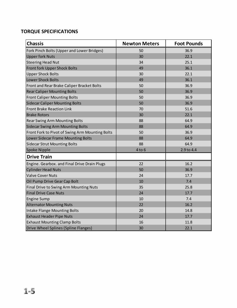
TORQUE SPECIFICATIONS
Chassis Newton Meters Foot PoundsFork Pinch Bolts (Upper and Lower Bridges) 50 36.9
Upper fork Nuts 30 22.1
Steering Head Nut 34 25.1
Front fork Upper Shock Bolts 49 36.1
Upper Shock Bolts 30 22.1
Lower Shock Bolts 49 36.1
Front and Rear Brake Caliper Bracket Bolts 50 36.9
Rear Caliper Mounting Bolts 50 36.9
Front Caliper Mounting Bolts 50 36.9
Sidecar Caliper Mounting Bolts 50 36.9
Front Brake Reaction Link 70 51.6
Brake Rotors 30 22.1
Rear Swing Arm Mounting Bolts 88 64.9
Sidecar Swing Arm Mounting Bolts 88 64.9
Front Fork to Pivot of Swing Arm Mounting Bolts 50 36.9
Lower Sidecar Frame Mounting Bolts 88 64.9
Sidecar Strut Mounting Bolts 88 64.9
Spoke Nipple 4 to 6 2.9 to 4.4
Drive TrainEngine. Gearbox. and Final Drive Drain Plugs 22 16.2
Cylinder Head Nuts 50 36.9
Valve Cover Nuts 24 17.7
Oil Pump Drive Gear Cap Bolt 10 7.4
Final Drive to Swing Arm Mounting Nuts 35 25.8
Final Drive Case Nuts 24 17.7
Engine Sump 10 7.4
Alternator Mounting Nuts 22 16.2
Intake Flange Mounting Bolts 20 14.8
Exhaust Header Pipe Nuts 24 17.7
Exhaust Mounting Clamp Bolts 16 11.8
Drive Wheel Splines (Spline Flanges) 30 22.1
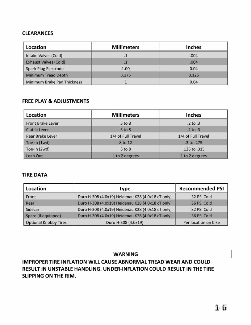
CLEARANCES
Location Millimeters Inches
Intake Valves (Cold) .1 .004
Exhaust Valves (Cold) .1 .004
Spark Plug Electrode 1.00 0.04
Minimum Tread Depth 3.175 0.125
Minimum Brake Pad Thickness 1 0.04
FREE PLAY & ADJUSTMENTS
Location Millimeters Inches
Front Brake Lever 5 to 8 .2 to .3
Clutch Lever 5 to 8 .2 to .3
Rear Brake Lever 1/4 of Full Travel 1/4 of Full Travel
Toe-In (1wd) 8 to 12 .3 to .475
Toe-In (2wd) 3 to 8 .125 to .315
Lean Out 1 to 2 degrees 1 to 2 degrees
TIRE DATA
Location Type Recommended PSI
Front Duro H-308 (4.0x19) Heidenau K28 (4.0x18 cT only) 32 PSI Cold
Rear Duro H-308 (4.0x19) Heidenau K28 (4.0x18 cT only) 36 PSI Cold
Sidecar Duro H-308 (4.0x19) Heidenau K28 (4.0x18 cT only) 32 PSI Cold
Spare (if equipped) Duro H-308 (4.0x19) Heidenau K28 (4.0x18 cT only) 36 PSI Cold
Optional Knobby Tires Duro H-308 (4.0x19) Per location on bike
WARNING
IMPROPER TIRE INFLATION WILL CAUSE ABNORMAL TREAD WEAR AND COULD RESULT IN UNSTABLE HANDLING. UNDER-INFLATION COULD RESULT IN THE TIRE SLIPPING ON THE RIM.
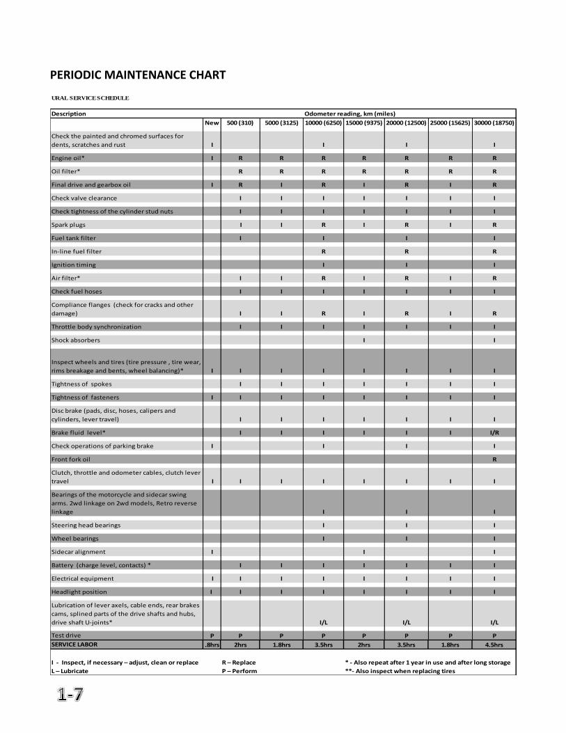
PERIODIC MAINTENANCE CHART
URAL SERVICE SCHEDULE
Description Odometer reading, km (miles)
New 500 (310) 5000 (3125) 10000 (6250) 15000 (9375) 20000 (12500) 25000 (15625) 30000 (18750)
Check the painted and chromed surfaces for
dents, scratches and rust I I I I
Engine oil* I R R R R R R R
Oil filter* R R R R R R R
Final drive and gearbox oil I R I R I R I R
Check valve clearance I I I I I I I
Check tightness of the cylinder stud nuts I I I I I I I
Spark plugs I I R I R I R
Fuel tank filter I I I I
In-line fuel filter R R R
Ignition timing I I I
Air filter* I I R I R I R
Check fuel hoses I I I I I I I
Compliance flanges (check for cracks and other
damage) I I R I R I R
Throttle body synchronization I I I I I I I
Shock absorbers I I
Inspect wheels and tires (tire pressure , tire wear,
rims breakage and bents, wheel balancing)* I I I I I I I I
Tightness of spokes I I I I I I I
Tightness of fasteners I I I I I I I I
Disc brake (pads, disc, hoses, calipers and
cylinders, lever travel) I I I I I I I
Brake fluid level* I I I I I I I/R
Check operations of parking brake I I I I
Front fork oil R
Clutch, throttle and odometer cables, clutch lever
travel I I I I I I I I
Bearings of the motorcycle and sidecar swing
arms. 2wd linkage on 2wd models, Retro reverse
linkage I I I
Steering head bearings I I I
Wheel bearings I I I
Sidecar alignment I I I
Battery (charge level, contacts) * I I I I I I I
Electrical equipment I I I I I I I I
Headlight position I I I I I I I I
Lubrication of lever axels, cable ends, rear brakes
cams, splined parts of the drive shafts and hubs,
drive shaft U-joints* I/L I/L I/L
Test drive P P P P P P P P
SERVICE LABOR .8hrs 2hrs 1.8hrs 3.5hrs 2hrs 3.5hrs 1.8hrs 4.5hrs
I - Inspect, if necessary – adjust, clean or replace R – Replace * - Also repeat after 1 year in use and after long storage
L – Lubricate P – Perform **- Also inspect when replacing tires
MOTORCYCLE STORAGE AND CARE
Storage If you will be storing your motorcycle for the winter or long term, take the following steps:
1. The motorcycle should be cleaned. 2. Check all fluid levels and add as necessary. 3. Check tire pressure. 4. Lubricate all shafts, splines, cables and joints. 5. Use a battery maintenance charger or disconnect battery. 6. Always store in a warm dry place to avoid rust and moisture build up. 7. Use a protective cover when needed.
After storage take the following steps prior to running your motorcycle:
1. Perform the pre-ride inspection. 2. Reconnect battery and/or disconnect charger. 3. Follow starting procedures. 4. Take the motorcycle for a short ride prior to any long trips.
CLEANING It is important to maintain your motorcycle properly and clean on a regular basis. Use the following guidelines when washing your motorcycle:
Make sure the engine is completely cool
Use warm soapy water and wash thoroughly
Avoid water from entering the air filter and electrical components
After washing dry the motorcycle with a cloth
Lubricate joints and cables as necessary
Run motorcycle to evaporate remaining water WINTER CONSIDERATIONS Motorists in many areas of the US experience the use of salt and other chemicals that are applied to road surfaces in the winter. Salt and other caustic chemicals should always be washed of you bike with fresh water as soon as possible to avoid rust and corrosion.
NOTE
RUSTED OR CORRODED PARTS CAUSED BY SALT ARE NOT COVERED BY WARRANTY.
2. Motorcycle Controls & Instrumentation
Page
Hand Controls 2-2
Foot Controls 2-3
Ignition Switch 2-4
Indicator Lamps 2-4
Speedometer Functions 2-5
Speedometer Operation 2-6
Parking Brake 2-7
Reverse Lever 2-7
Kick Starter 2-8
2wd Engagement Lever 2-8
Hydraulic Spring Shock Absorbers 2-9
Hydraulic Steering Damper 2-9
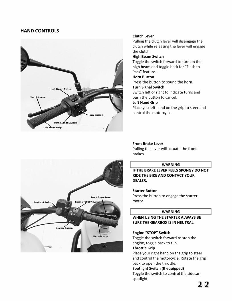
HAND CONTROLS
Clutch Lever Pulling the clutch lever will disengage the clutch while releasing the lever will engage the clutch. High Beam Switch Toggle the switch forward to turn on the high beam and toggle back for “Flash to Pass” feature. Horn Button Press the button to sound the horn. Turn Signal Switch Switch left or right to indicate turns and push the button to cancel. Left Hand Grip Place you left hand on the grip to steer and control the motorcycle.
Front Brake Lever Pulling the lever will actuate the front brakes.
WARNING
IF THE BRAKE LEVER FEELS SPONGY DO NOT RIDE THE BIKE AND CONTACT YOUR DEALER. Starter Button Press the button to engage the starter motor.
WARNING
WHEN USING THE STARTER ALWAYS BE SURE THE GEARBOX IS IN NEUTRAL. Engine “STOP” Switch Toggle the switch forward to stop the engine, toggle back to run. Throttle Grip Place your right hand on the grip to steer and control the motorcycle. Rotate the grip back to open the throttle. Spotlight Switch (If equipped) Toggle the switch to control the sidecar spotlight.
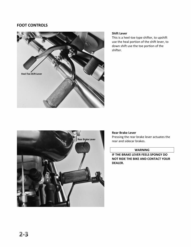
FOOT CONTROLS
Shift Lever This is a heel-toe type shifter, to upshift use the heal portion of the shift lever, to down shift use the toe portion of the shifter.
Rear Brake Lever Pressing the rear brake lever actuates the rear and sidecar brakes.
WARNING
IF THE BRAKE LEVER FEELS SPONGY DO NOT RIDE THE BIKE AND CONTACT YOUR DEALER.
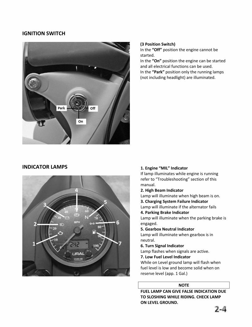
IGNITION SWITCH
INDICATOR LAMPS
1. Engine “MIL” Indicator If lamp illuminates while engine is running refer to “Troubleshooting” section of this manual. 2. High Beam Indicator Lamp will illuminate when high beam is on. 3. Charging System Failure Indicator Lamp will illuminate if the alternator fails 4. Parking Brake Indicator Lamp will illuminate when the parking brake is engaged. 5. Gearbox Neutral Indicator Lamp will illuminate when gearbox is in neutral. 6. Turn Signal Indicator Lamp flashes when signals are active. 7. Low Fuel Level Indicator While on Level ground lamp will flash when fuel level is low and become solid when on reserve level (app. 1 Gal.)
NOTE
FUEL LAMP CAN GIVE FALSE INDICATION DUE TO SLOSHING WHILE RIDING. CHECK LAMP ON LEVEL GROUND.
(3 Position Switch) In the “Off” position the engine cannot be started. In the “On” position the engine can be started and all electrical functions can be used. In the “Park” position only the running lamps (not including headlight) are illuminated.
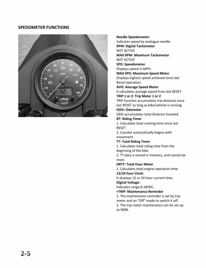
SPEDOMETER FUNCTIONS
Needle Speedometer: Indicates speed by analogue needle. RPM: Digital Tachometer NOT ACTIVE MAX RPM: Maximum Tachometer NOT ACTIVE SPD: Speedometer Displays speed in MPH. MAX SPD: Maximum Speed Meter Displays highest speed achieved since last Reset operation. AVG: Average Speed Meter It calculates average speed from last RESET. TRIP 1 or 2: Trip Meter 1 or 2 TRIP function accumulates trip distance since last RESET as long as bike/vehicle is moving. ODO: Odometer ODO accumulates total distance traveled. RT: Riding Timer 1. Calculates total running time since last RESET. 2. Counter automatically begins with movement. TT: Total Riding Timer 1. Calculates total riding time from the beginning of the bike. 2. TT data is stored in memory, and cannot be reset. HRTT: Total Hour Meter 1. Calculates total engine operation time. 12/24 hour Clock: It displays 12 or 24 hour current time. Digital Voltage: Indicates range 8-18VDC. +TRIP: Maintenance Reminder 1. The maintenance reminder is set by trip meter and an “Off” mode to switch it off. 2. The trip meter maintenance can be set up to 9999.
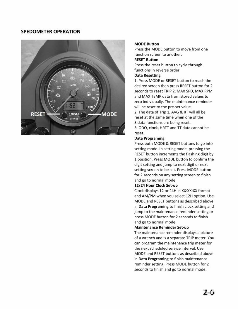
SPEDOMETER OPERATION
MODE Button Press the MODE button to move from one function screen to another. RESET Button Press the reset button to cycle through functions in reverse order. Data Resetting 1. Press MODE or RESET button to reach the desired screen then press RESET button for 2 seconds to reset TRIP 2, MAX SPD, MAX RPM and MAX TEMP data from stored values to zero individually. The maintenance reminder will be reset to the pre-set value. 2. The data of Trip 1, AVG & RT will all be reset at the same time when one of the 3 data functions are being reset. 3. ODO, clock, HRTT and TT data cannot be reset. Data Programing Press both MODE & RESET buttons to go into setting mode. In setting mode, pressing the RESET button increments the flashing digit by 1 position. Press MODE button to confirm the digit setting and jump to next digit or next setting screen to be set. Press MODE button for 2 seconds on any setting screen to finish and go to normal mode. 12/24 Hour Clock Set-up Clock displays 12 or 24H in XX:XX:XX format and AM/PM when you select 12H option. Use MODE and RESET buttons as described above in Data Programing to finish clock setting and jump to the maintenance reminder setting or press MODE button for 2 seconds to finish and go to normal mode. Maintenance Reminder Set-up The maintenance reminder displays a picture of a wrench and is a separate TRIP meter. You can program the maintenance trip meter for the next scheduled service interval. Use MODE and RESET buttons as described above in Data Programing to finish maintenance reminder setting. Press MODE button for 2 seconds to finish and go to normal mode.
PARKING BRAKE
REVERSE LEVER
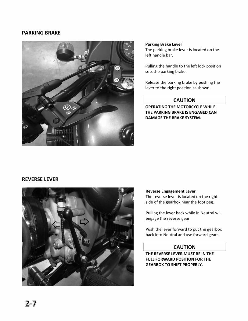
Parking Brake Lever The parking brake lever is located on the left handle bar. Pulling the handle to the left lock position sets the parking brake. Release the parking brake by pushing the lever to the right position as shown.
CAUTION OPERATING THE MOTORCYCLE WHILE THE PARKING BRAKE IS ENGAGED CAN DAMAGE THE BRAKE SYSTEM.
Reverse Engagement Lever The reverse lever is located on the right side of the gearbox near the foot peg. Pulling the lever back while in Neutral will engage the reverse gear. Push the lever forward to put the gearbox back into Neutral and use forward gears.
CAUTION THE REVERSE LEVER MUST BE IN THE FULL FORWARD POSITION FOR THE GEARBOX TO SHIFT PROPERLY.
KICK START LEVER
2WD ENGAGEMENT LEVER
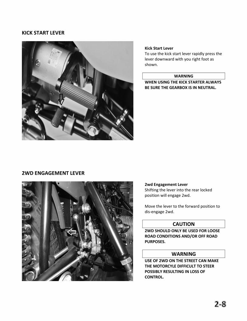
2wd Engagement Lever Shifting the lever into the rear locked position will engage 2wd. Move the lever to the forward position to dis-engage 2wd.
CAUTION 2WD SHOULD ONLY BE USED FOR LOOSE ROAD CONDITIONS AND/OR OFF ROAD PURPOSES.
WARNING USE OF 2WD ON THE STREET CAN MAKE THE MOTORCYLE DIFFICULT TO STEER POSSIBLY RESULTING IN LOSS OF CONTROL.
Kick Start Lever To use the kick start lever rapidly press the lever downward with you right foot as shown.
WARNING
WHEN USING THE KICK STARTER ALWAYS BE SURE THE GEARBOX IS IN NEUTRAL.
HYDRAULIC SPRING SHOCK ABSORBERS
HYDRAULIC STEERING DAMPER
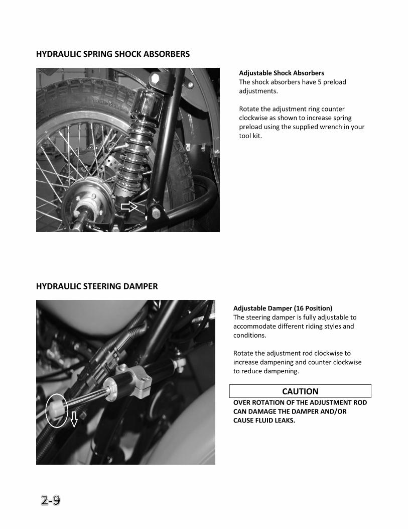
Adjustable Shock Absorbers The shock absorbers have 5 preload adjustments. Rotate the adjustment ring counter clockwise as shown to increase spring preload using the supplied wrench in your tool kit.
Adjustable Damper (16 Position) The steering damper is fully adjustable to accommodate different riding styles and conditions. Rotate the adjustment rod clockwise to increase dampening and counter clockwise to reduce dampening.
CAUTION OVER ROTATION OF THE ADJUSTMENT ROD CAN DAMAGE THE DAMPER AND/OR CAUSE FLUID LEAKS.
3. Motorcycle Operation
Page
Pre-ride Inspections 3-2
Initial Ride Instructions 3-2
Sidecar Safety 3-3
Starting Procedures 3-5
Run-In 3-6
PRE-RIDE INSPECTIONS
Prior to each ride you should inspect the motorcycles technical condition for safety. Use
the following pre-ride inspection list to ensure your motorcycle is safe and ready to ride.
1. Check the oil level. Low oil level causes premature wear and possible engine damage.
2. Check the fuel level. 3. Check the tire pressure. Low tire pressure can cause poor handling, also inspect
the tire for abnormal and/or excessive wear that may lead to a flat tire. 4. Check all lights for proper operations including headlight, running lights, turn
signals, and brake lights. 5. Check the brakes for proper operations and correct fluid level. If for any reason
the brakes feel abnormal or spongy do not ride the bike as it may be unsafe. 6. Inspect all cables to insure they are not pinched or routed improperly; also
inspect the clutch cable for correct free play. 7. Check for any loose fasteners and tighten as necessary. 8. Be sure any luggage is secured before riding.
INSTRUCTIONS FOR INITIAL RIDE
The following steps should be taken prior and during your first ride:
1. Read the entire owner’s manual prior to starting and/or taking you first ride. 2. Familiarize yourself with all controls and instruments. 3. Make any required adjustments to mirrors and controls for comfort. 4. Always wear safety gear including but not limited to: helmet, boots, gloves, and
jacket regardless of weather. 5. Ride in a safe environment such as a parking lot or area you are familiar with
while you learn the specific handling characteristics of your new sidecar motorcycle.
6. Follow the “Engine Run-in” instructions.
SIDECAR SAFETY
The Ural sidecar motorcycle, since it has three wheels, behaves quite differently from either a solo motorcycle or a car. For these reasons the following label has been attached to your motorcycle tank: WARNING: LEFT-HAND AND RIGHT-HAND TURNS MAY BE DANGEROUS. EXCESSIVE SPEED AND AN UNWEIGHTED SIDECAR MUST BE AVOIDED. Like any other motor vehicle, if the Ural is driven beyond its design limits, you can get hurt. Properly driven, since you have the added stability of the third wheel in case of sand, ice or slippery road conditions, the Ural will give you a much safer ride than a solo motorcycle in adverse conditions. If possible, an experienced sidecar driver (preferably your Authorized Ural dealer) should ride along during your first ride. If not, put about 100 LB of ballast in the sidecar during your initial training. Although an experienced driver can safely drive the Ural with an empty sidecar a beginner should always have ballast or a passenger in the chair. Check with your local IMWA Dealer to find out your particular state’s sidecar driver’s license requirements. When you accelerate, the Ural will pull slightly to the right due to the inertia and drag of the side car. When you let off the gas it will pull slightly to the left due to the inertia of the sidecar. Practice starting and stopping from various speeds, shifting up and down, accelerating and decelerating in each gear, turning right and left at slow-to-medium speeds.
WARNING
The Patrol and Gear-up with engageable sidecar wheel handles differently with the sidecar driveshaft engaged and cannot turn on paved roads. For this reason, the sidecar drive must only be engaged when operating the vehicle off-road or where snow, ice and mud conditions are encountered on road.
SIDECAR SAFETY (CONT.)
Finally, practice lifting the sidecar. To do this drive in a clockwise circle about 20 feet in diameter. Gradually increase your speed until the sidecar wheel lifts from the surface 6 - 12 inches. Then roll off the throttle and ease steering pressure on the grips so it gradually comes back down. Repeat doing this until you feel comfortable with the wheel in the air. Remember, the moment you roll off the throttle it will come down. When you have mastered “flying the chair” to the point where you can keep it in the air for a full circle you will have a good feel for the speed and turn radius that will lift the sidecar. If, after gaining proficiency with the Ural, you plan to drive on the street with an empty sidecar, go back to the parking lot and practice the above maneuvers with an empty sidecar. You’ll find that the sidecar will lift much more readily when it is empty, especially if you enter a decreasing radius turn (such as a freeway off ramp) at too high a speed. This is why we recommend generally carrying about 100 lbs or more in the sidecar.
WARNING
BALLAST WEIGHT SHOULD ALWAYS BE PROPERLY SECURED IN THE SIDECAR AND CENTERED FOR BEST BALANCE.
STARTING THE ENGINE WHEN COLD
Use the following instructions when starting a cold engine:
1. Check to be sure you have enough fuel. 2. Switch ignition on. 3. Be sure the transmission is in neutral. 4. Switch the kill switch to run. 5. Press the starter button or use the kick starter until engine starts. 6. Allow engine to warm for a few moments prior to riding.
NOTE
ENGINE CRANKING SPEED CAN BE REDUCED IN COLD WEATHER, FOLLOW THE RECOMMENDATIONS FOR PROPER OIL WEIGHT FOUND ON PAGE 4-2.
CAUTION
DO NOT ACCELERATE WHILE STARTING THE BIKE! DO NOT RUN STARTER FOR MORE
THAN 5 SECONDS. NEVER STAND IN FRONT OF THE MOTORCYCLE WHILE THE ENGINE
IS RUNNING.
STARTING THE ENGINE WHEN WARM OR HOT
Use the following instructions when starting a warm or hot engine:
1. Check to be sure you have enough fuel. 2. Switch ignition on. 3. Be sure the transmission is in neutral. 4. Switch the kill switch to run. 5. Press the starter button or use the kick starter until engine starts.
CAUTION
DO NOT ACCELERATE WHILE STARTING THE BIKE! DO NOT RUN STARTER FOR MORE
THAN 5 SECONDS. NEVER STAND IN FRONT OF THE MOTORCYCLE WHILE THE ENGINE
IS RUNNING.
ENGINE RUN-IN
During the first 1000 kilometers it is important not to overload or over rev the engine
while riding. To ensure proper break-in you should ride the motorcycle conservatively at
varying speeds and loads. Use the following guidelines during the first 1000 kilometers
prior to the initial break-in service:
1. Do not overload or “lug” the engine. 2. Do not exceed a top speed beyond 60mph. 3. Do not ride at a constant rpm for long periods of time. 4. Try to vary speed and load when riding. 5. Shift smoothly between gears and do not down shift at high rpm. 6. Always be sure the engine is warmed up before riding. 7. Follow the pre-ride inspection.
4. Lubrication
Page
Recommended Fluids, Lubricants & Capacities 4-2
Lubrication Diagram 4-3
Lubrication Points 4-4
Engine oil and filter replacement 4-5
Gearbox oil replacement 4-7
Final drive oil replacement 4-8
Drive Shaft Lubrication 4-9
Cable Lubrication 4-10
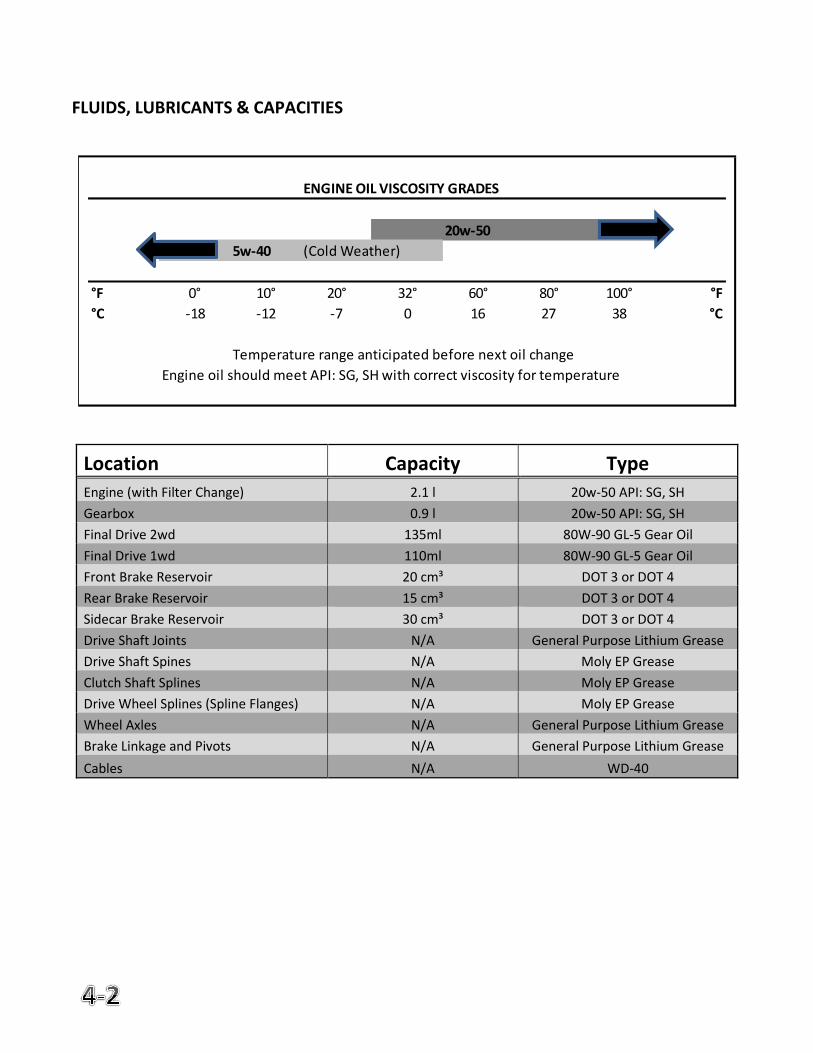
FLUIDS, LUBRICANTS & CAPACITIES
Location Capacity Type
Engine (with Filter Change) 2.1 l 20w-50 API: SG, SH
Gearbox 0.9 l 20w-50 API: SG, SH
Final Drive 2wd 135ml 80W-90 GL-5 Gear Oil
Final Drive 1wd 110ml 80W-90 GL-5 Gear Oil
Front Brake Reservoir 20 cm³ DOT 3 or DOT 4
Rear Brake Reservoir 15 cm³ DOT 3 or DOT 4
Sidecar Brake Reservoir 30 cm³ DOT 3 or DOT 4
Drive Shaft Joints N/A General Purpose Lithium Grease
Drive Shaft Spines N/A Moly EP Grease
Clutch Shaft Splines N/A Moly EP Grease
Drive Wheel Splines (Spline Flanges) N/A Moly EP Grease
Wheel Axles N/A General Purpose Lithium Grease
Brake Linkage and Pivots N/A General Purpose Lithium Grease
Cables N/A WD-40
ENGINE OIL VISCOSITY GRADES
20w-50
5w-40 (Cold Weather)
°F 0° 10° 20° 32° 60° 80° 100° °F
°C -18 -12 -7 0 16 27 38 °C
Temperature range anticipated before next oil change
Engine oil should meet API: SG, SH with correct viscosity for temperature
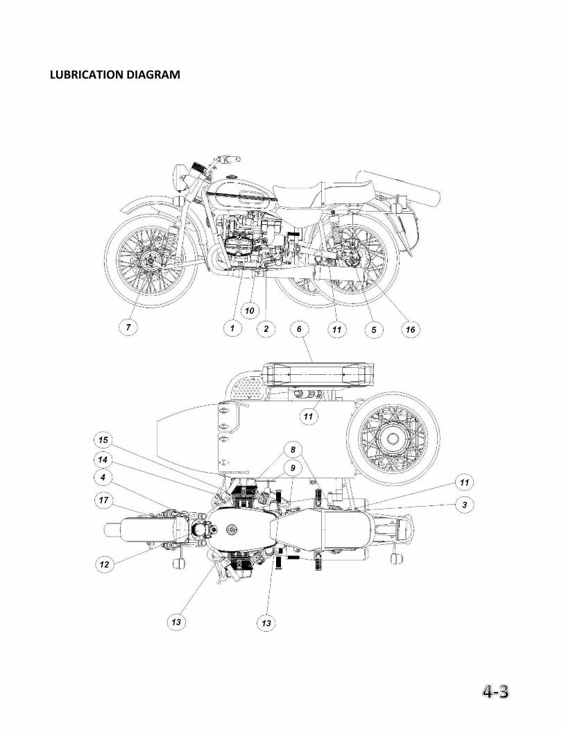
LUBRICATION DIAGRAM
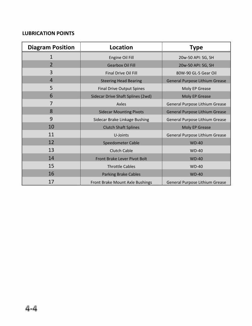
LUBRICATION POINTS
Diagram Position Location Type
1 Engine Oil Fill 20w-50 API: SG, SH
2 Gearbox Oil Fill 20w-50 API: SG, SH
3 Final Drive Oil Fill 80W-90 GL-5 Gear Oil
4 Steering Head Bearing General Purpose Lithium Grease
5 Final Drive Output Spines Moly EP Grease
6 Sidecar Drive Shaft Splines (2wd) Moly EP Grease
7 Axles General Purpose Lithium Grease
8 Sidecar Mounting Pivots General Purpose Lithium Grease
9 Sidecar Brake Linkage Bushing General Purpose Lithium Grease
10 Clutch Shaft Splines Moly EP Grease
11 U-Joints General Purpose Lithium Grease
12 Speedometer Cable WD-40
13 Clutch Cable WD-40
14 Front Brake Lever Pivot Bolt WD-40
15 Throttle Cables WD-40
16 Parking Brake Cables WD-40
17 Front Brake Mount Axle Bushings General Purpose Lithium Grease
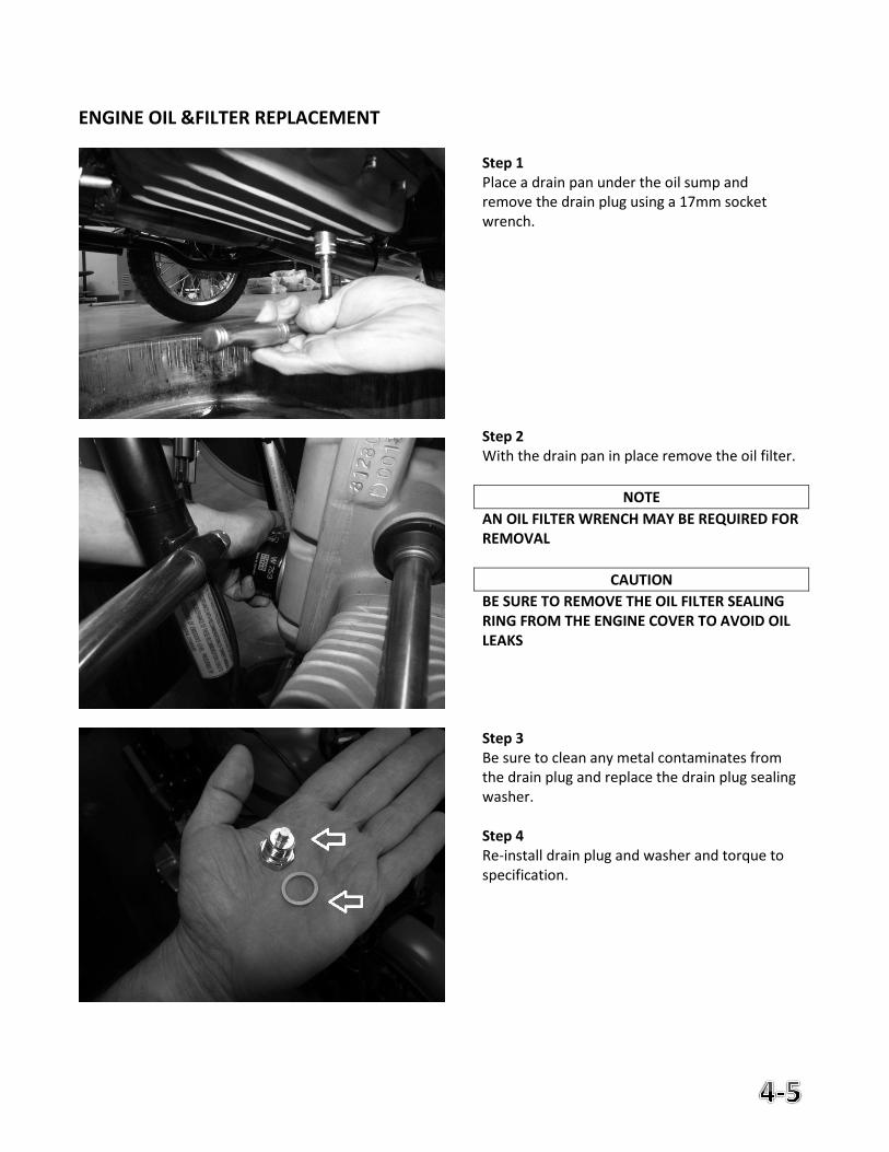
ENGINE OIL &FILTER REPLACEMENT
Step 1 Place a drain pan under the oil sump and remove the drain plug using a 17mm socket wrench. Step 2 With the drain pan in place remove the oil filter.
NOTE
AN OIL FILTER WRENCH MAY BE REQUIRED FOR REMOVAL
CAUTION
BE SURE TO REMOVE THE OIL FILTER SEALING RING FROM THE ENGINE COVER TO AVOID OIL LEAKS Step 3 Be sure to clean any metal contaminates from the drain plug and replace the drain plug sealing washer. Step 4 Re-install drain plug and washer and torque to specification.
ENGINE OIL & FILTER REPLACEMENT (CONT.)
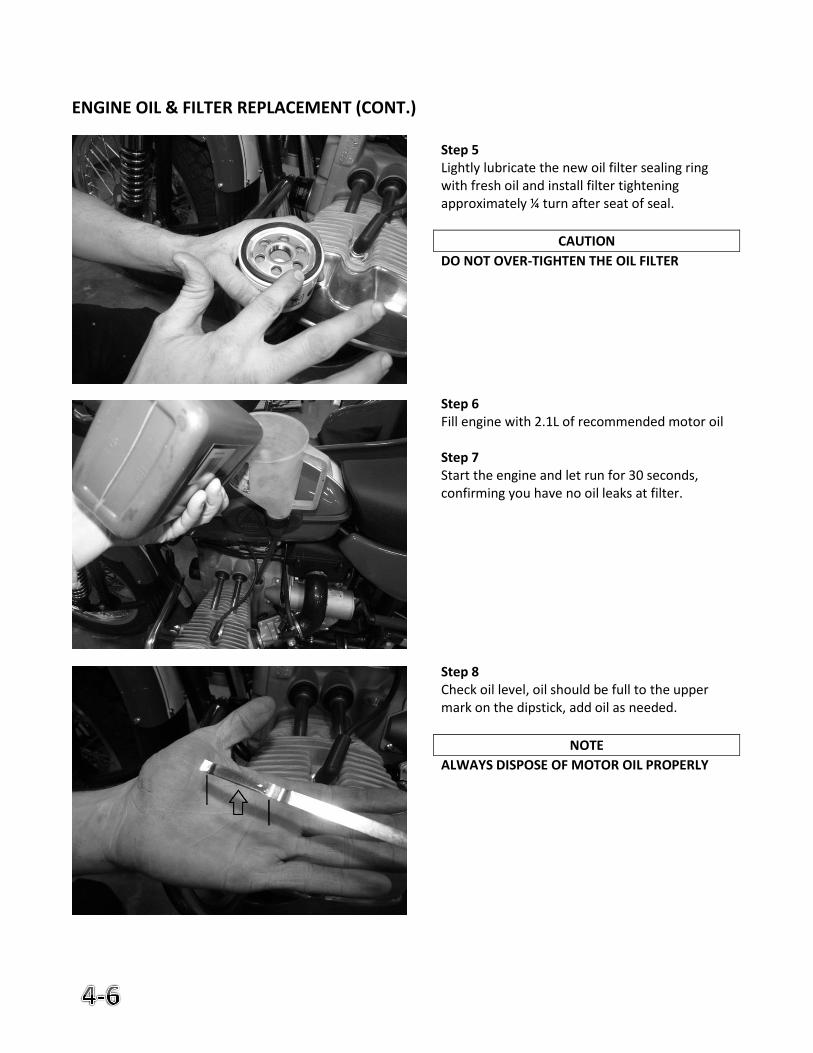
Step 5 Lightly lubricate the new oil filter sealing ring with fresh oil and install filter tightening approximately ¼ turn after seat of seal.
CAUTION
DO NOT OVER-TIGHTEN THE OIL FILTER Step 6 Fill engine with 2.1L of recommended motor oil Step 7 Start the engine and let run for 30 seconds, confirming you have no oil leaks at filter. Step 8 Check oil level, oil should be full to the upper mark on the dipstick, add oil as needed.
NOTE
ALWAYS DISPOSE OF MOTOR OIL PROPERLY
GEARBOX OIL REPLACEMENT
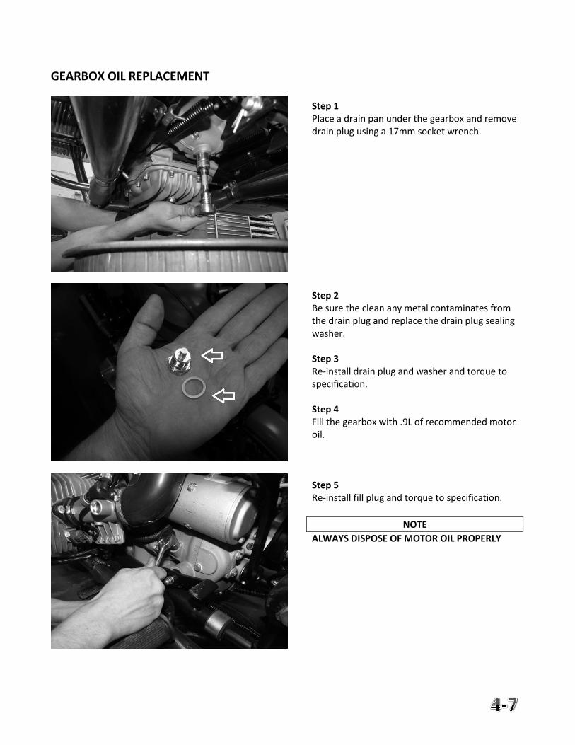
Step 1 Place a drain pan under the gearbox and remove drain plug using a 17mm socket wrench. Step 2 Be sure the clean any metal contaminates from the drain plug and replace the drain plug sealing washer. Step 3 Re-install drain plug and washer and torque to specification. Step 4 Fill the gearbox with .9L of recommended motor oil. Step 5 Re-install fill plug and torque to specification.
NOTE
ALWAYS DISPOSE OF MOTOR OIL PROPERLY
FINAL DRIVE OIL REPLACEMENT
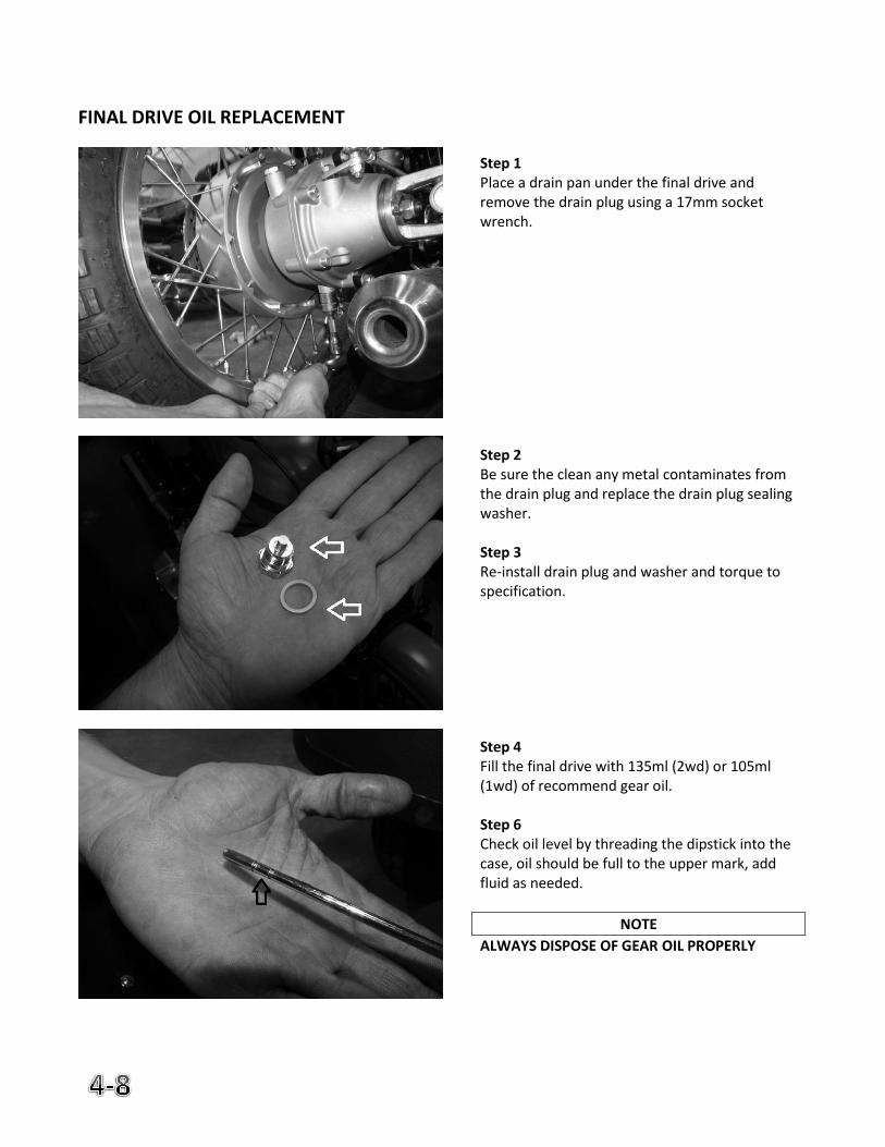
Step 1 Place a drain pan under the final drive and remove the drain plug using a 17mm socket wrench. Step 2 Be sure the clean any metal contaminates from the drain plug and replace the drain plug sealing washer. Step 3 Re-install drain plug and washer and torque to specification. Step 4 Fill the final drive with 135ml (2wd) or 105ml (1wd) of recommend gear oil. Step 6 Check oil level by threading the dipstick into the case, oil should be full to the upper mark, add fluid as needed.
NOTE
ALWAYS DISPOSE OF GEAR OIL PROPERLY
DRIVE SHAFT & SPLINE LUBRICATION
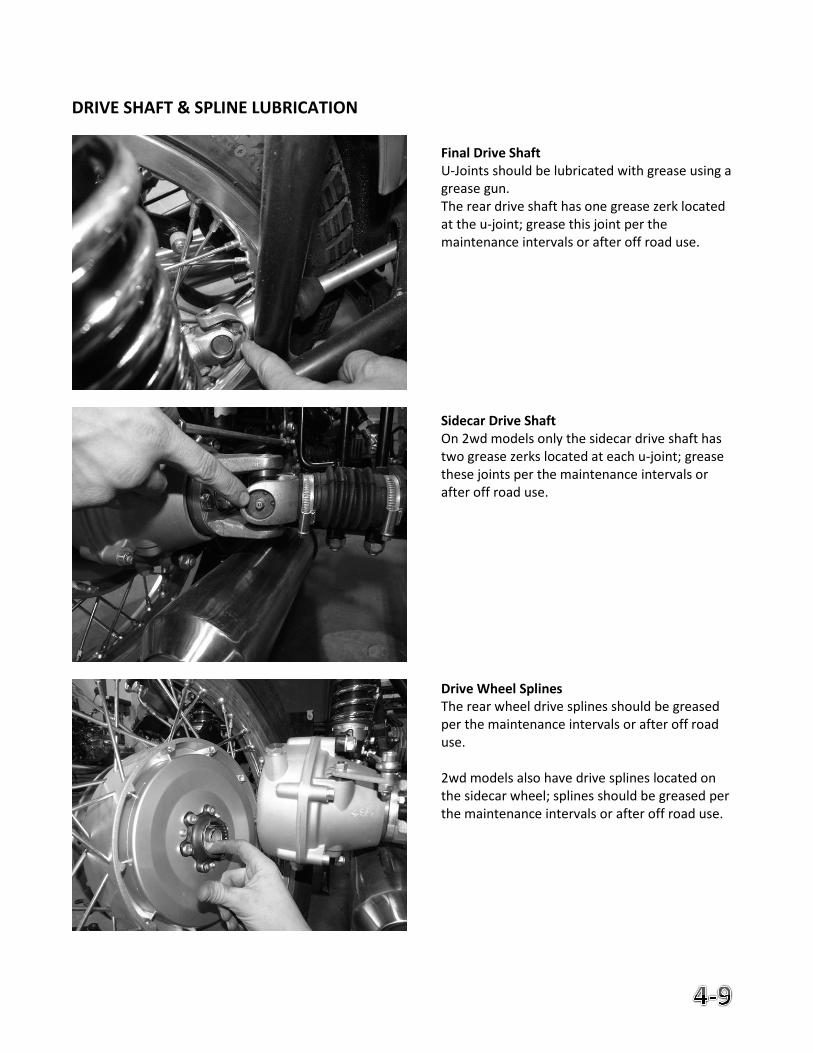
Final Drive Shaft U-Joints should be lubricated with grease using a grease gun. The rear drive shaft has one grease zerk located at the u-joint; grease this joint per the maintenance intervals or after off road use. Sidecar Drive Shaft On 2wd models only the sidecar drive shaft has two grease zerks located at each u-joint; grease these joints per the maintenance intervals or after off road use. Drive Wheel Splines The rear wheel drive splines should be greased per the maintenance intervals or after off road use. 2wd models also have drive splines located on the sidecar wheel; splines should be greased per the maintenance intervals or after off road use.
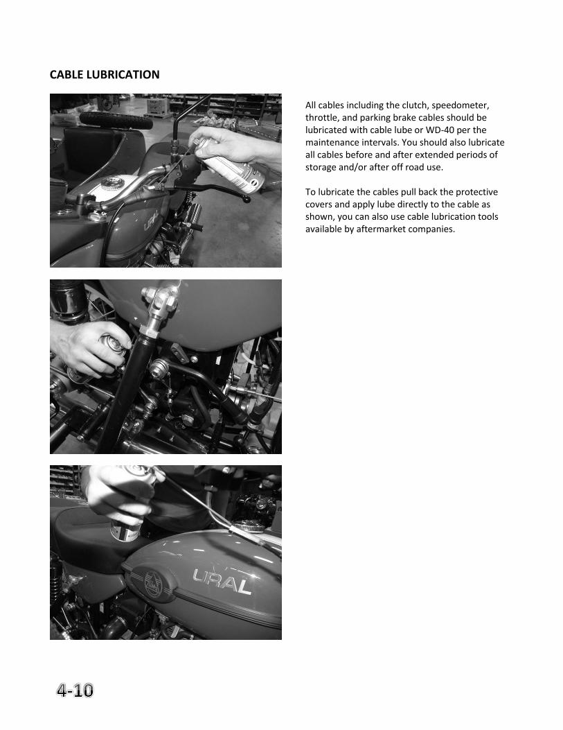
CABLE LUBRICATION
All cables including the clutch, speedometer, throttle, and parking brake cables should be lubricated with cable lube or WD-40 per the maintenance intervals. You should also lubricate all cables before and after extended periods of storage and/or after off road use. To lubricate the cables pull back the protective covers and apply lube directly to the cable as shown, you can also use cable lubrication tools available by aftermarket companies.
5. Engine & Chassis Maintenance
Page
Air filter Inspection & Replacement 5-2
Fuel System Maintenance 5-3
Valve Train Inspection & Adjustment 5-5
Front Brake System Maintenance 5-7
Rear Brake System Maintenance 5-9
Parking Brake Adjustment 5-11
Sidecar Brake System Maintenance 5-12
Wheel Removal & Installation 5-14
Using the Spare Wheel 5-22
Spoke Maintenance 5-22
Wheel Bearing Replacement & Diagrams 5-23
Tire & Tube Replacement 5-24
Sidecar Alignment 5-25
Sidecar Alignment Diagram 5-26
AIR FILTER INSPECTION & REPLACEMENT
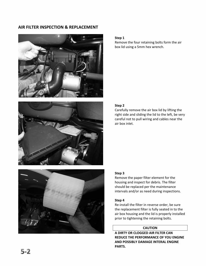
Step 1 Remove the four retaining bolts form the air box lid using a 5mm hex wrench. Step 2 Carefully remove the air box lid by lifting the right side and sliding the lid to the left, be very careful not to pull wiring and cables near the air box inlet. Step 3 Remove the paper filter element for the housing and inspect for debris. The filter should be replaced per the maintenance intervals and/or as need during inspections. Step 4 Re-install the filter in reverse order, be sure the replacement filter is fully seated in to the air box housing and the lid is properly installed prior to tightening the retaining bolts.
CAUTION
A DIRTY OR CLOGGED AIR FILTER CAN REDUCE THE PERFORMANCE OF YOU ENGINE AND POSSIBLY DAMAGE INTERAL ENGINE PARTS.
FUEL SYSTEM MAINTENANCE
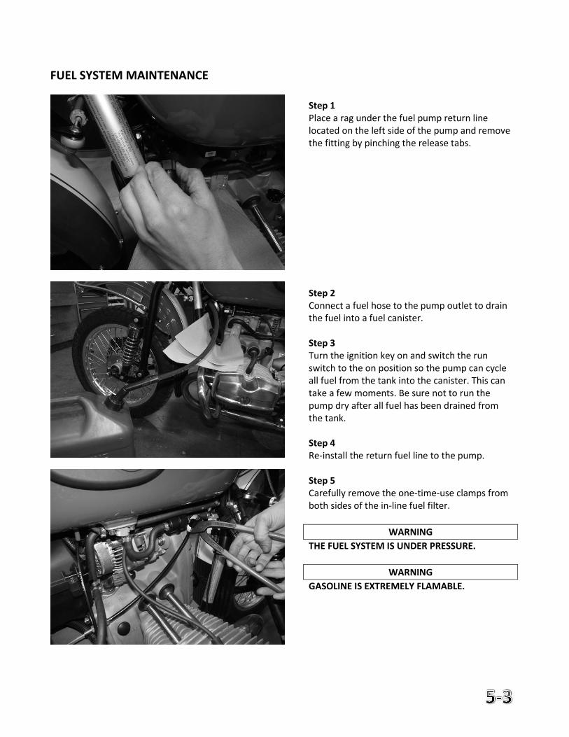
Step 1 Place a rag under the fuel pump return line located on the left side of the pump and remove the fitting by pinching the release tabs. Step 2 Connect a fuel hose to the pump outlet to drain the fuel into a fuel canister. Step 3 Turn the ignition key on and switch the run switch to the on position so the pump can cycle all fuel from the tank into the canister. This can take a few moments. Be sure not to run the pump dry after all fuel has been drained from the tank. Step 4 Re-install the return fuel line to the pump. Step 5 Carefully remove the one-time-use clamps from both sides of the in-line fuel filter.
WARNING
THE FUEL SYSTEM IS UNDER PRESSURE.
WARNING
GASOLINE IS EXTREMELY FLAMABLE.
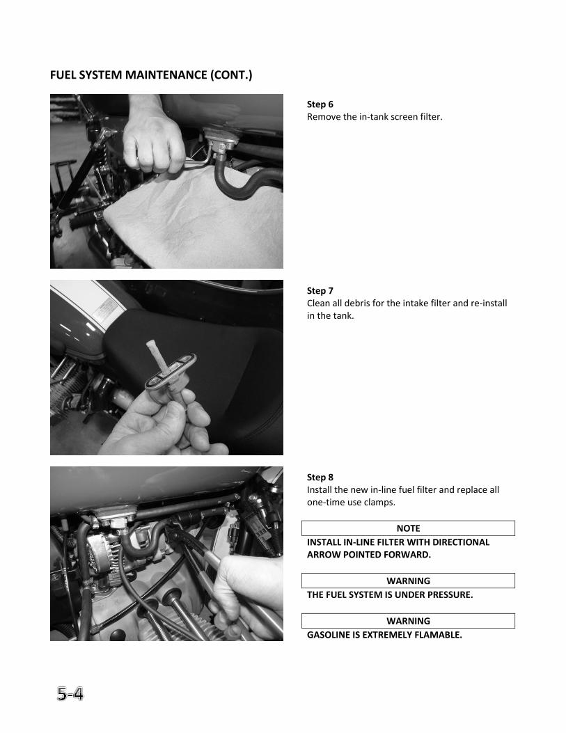
FUEL SYSTEM MAINTENANCE (CONT.)
Step 6 Remove the in-tank screen filter. Step 7 Clean all debris for the intake filter and re-install in the tank. Step 8 Install the new in-line fuel filter and replace all one-time use clamps.
NOTE
INSTALL IN-LINE FILTER WITH DIRECTIONAL ARROW POINTED FORWARD.
WARNING
THE FUEL SYSTEM IS UNDER PRESSURE.
WARNING
GASOLINE IS EXTREMELY FLAMABLE.
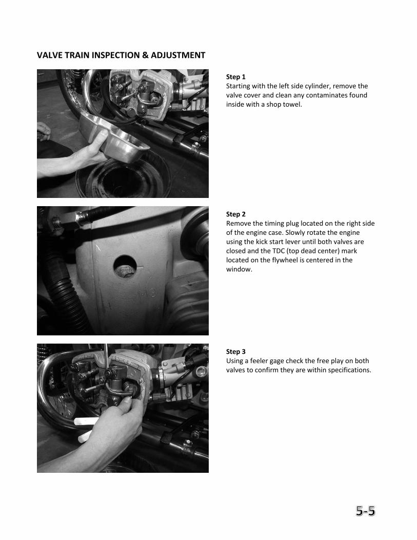
VALVE TRAIN INSPECTION & ADJUSTMENT
Step 1 Starting with the left side cylinder, remove the valve cover and clean any contaminates found inside with a shop towel. Step 2 Remove the timing plug located on the right side of the engine case. Slowly rotate the engine using the kick start lever until both valves are closed and the TDC (top dead center) mark located on the flywheel is centered in the window. Step 3 Using a feeler gage check the free play on both valves to confirm they are within specifications.
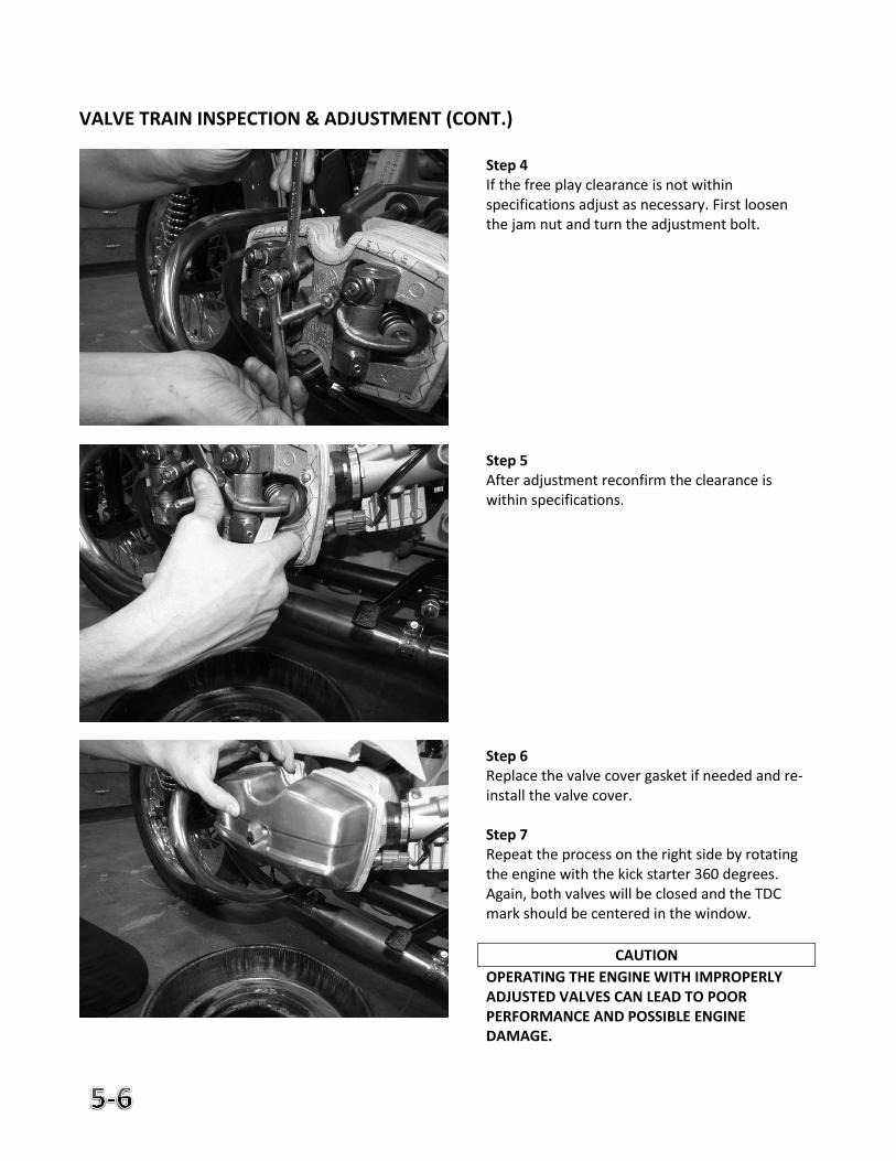
VALVE TRAIN INSPECTION & ADJUSTMENT (CONT.)
Step 4 If the free play clearance is not within specifications adjust as necessary. First loosen the jam nut and turn the adjustment bolt. Step 5 After adjustment reconfirm the clearance is within specifications. Step 6 Replace the valve cover gasket if needed and re-install the valve cover. Step 7 Repeat the process on the right side by rotating the engine with the kick starter 360 degrees. Again, both valves will be closed and the TDC mark should be centered in the window.
CAUTION
OPERATING THE ENGINE WITH IMPROPERLY ADJUSTED VALVES CAN LEAD TO POOR PERFORMANCE AND POSSIBLE ENGINE DAMAGE.
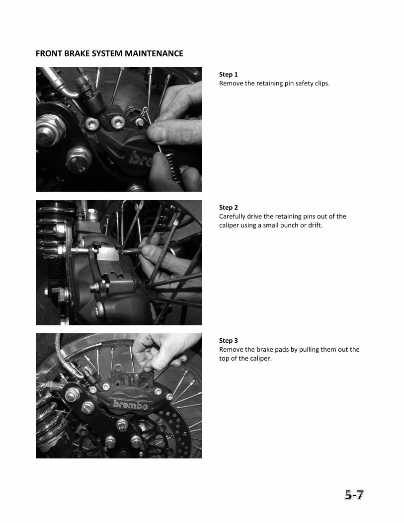
FRONT BRAKE SYSTEM MAINTENANCE
Step 1 Remove the retaining pin safety clips. Step 2 Carefully drive the retaining pins out of the caliper using a small punch or drift. Step 3 Remove the brake pads by pulling them out the top of the caliper.
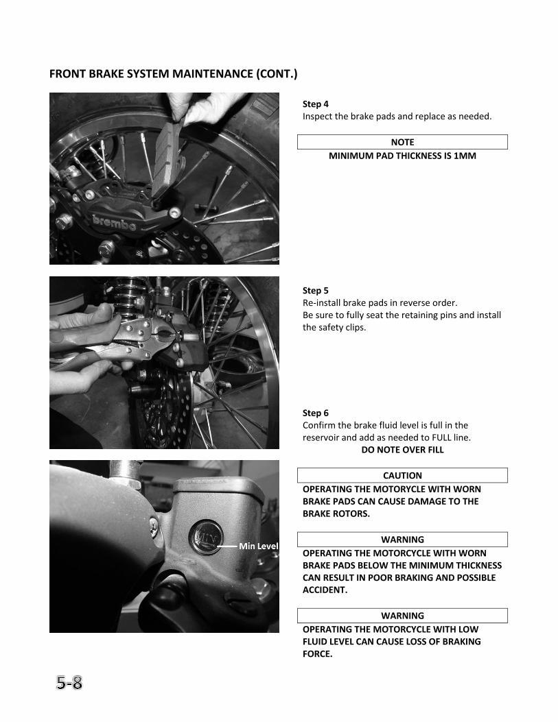
FRONT BRAKE SYSTEM MAINTENANCE (CONT.)
Step 4 Inspect the brake pads and replace as needed.
NOTE
MINIMUM PAD THICKNESS IS 1MM
Step 5 Re-install brake pads in reverse order. Be sure to fully seat the retaining pins and install the safety clips. Step 6 Confirm the brake fluid level is full in the reservoir and add as needed to FULL line.
DO NOTE OVER FILL
CAUTION
OPERATING THE MOTORYCLE WITH WORN BRAKE PADS CAN CAUSE DAMAGE TO THE BRAKE ROTORS.
WARNING
OPERATING THE MOTORCYCLE WITH WORN BRAKE PADS BELOW THE MINIMUM THICKNESS CAN RESULT IN POOR BRAKING AND POSSIBLE ACCIDENT.
WARNING
OPERATING THE MOTORCYCLE WITH LOW FLUID LEVEL CAN CAUSE LOSS OF BRAKING FORCE.
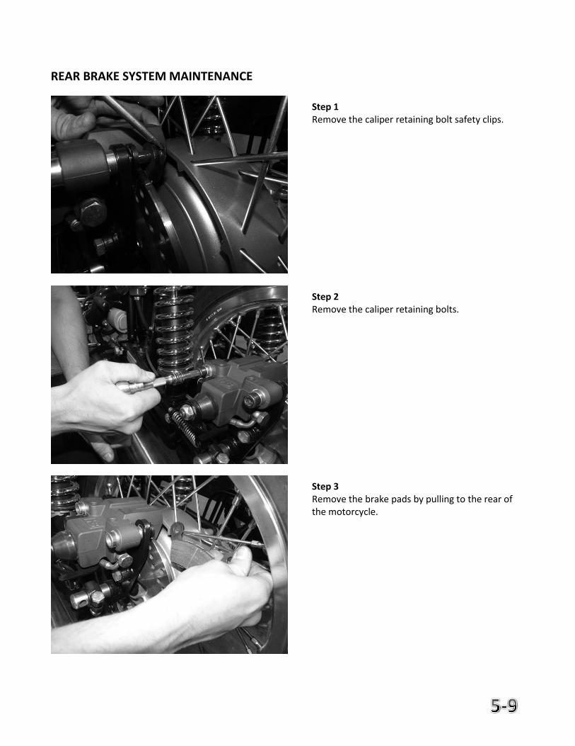
REAR BRAKE SYSTEM MAINTENANCE
Step 1 Remove the caliper retaining bolt safety clips. Step 2 Remove the caliper retaining bolts. Step 3 Remove the brake pads by pulling to the rear of the motorcycle.
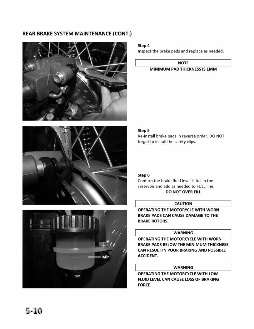
REAR BRAKE SYSTEM MAINTENANCE (CONT.)
Step 4 Inspect the brake pads and replace as needed.
NOTE
MINIMUM PAD THICKNESS IS 1MM
Step 5 Re-install brake pads in reverse order. DO NOT forget to install the safety clips. Step 6 Confirm the brake fluid level is full in the reservoir and add as needed to FULL line.
DO NOT OVER FILL
CAUTION
OPERATING THE MOTORYCLE WITH WORN BRAKE PADS CAN CAUSE DAMAGE TO THE BRAKE ROTORS.
WARNING
OPERATING THE MOTORCYCLE WITH WORN BRAKE PADS BELOW THE MINIMUM THICKNESS CAN RESULT IN POOR BRAKING AND POSSIBLE ACCIDENT.
WARNING
OPERATING THE MOTORCYCLE WITH LOW FLUID LEVEL CAN CAUSE LOSS OF BRAKING FORCE.
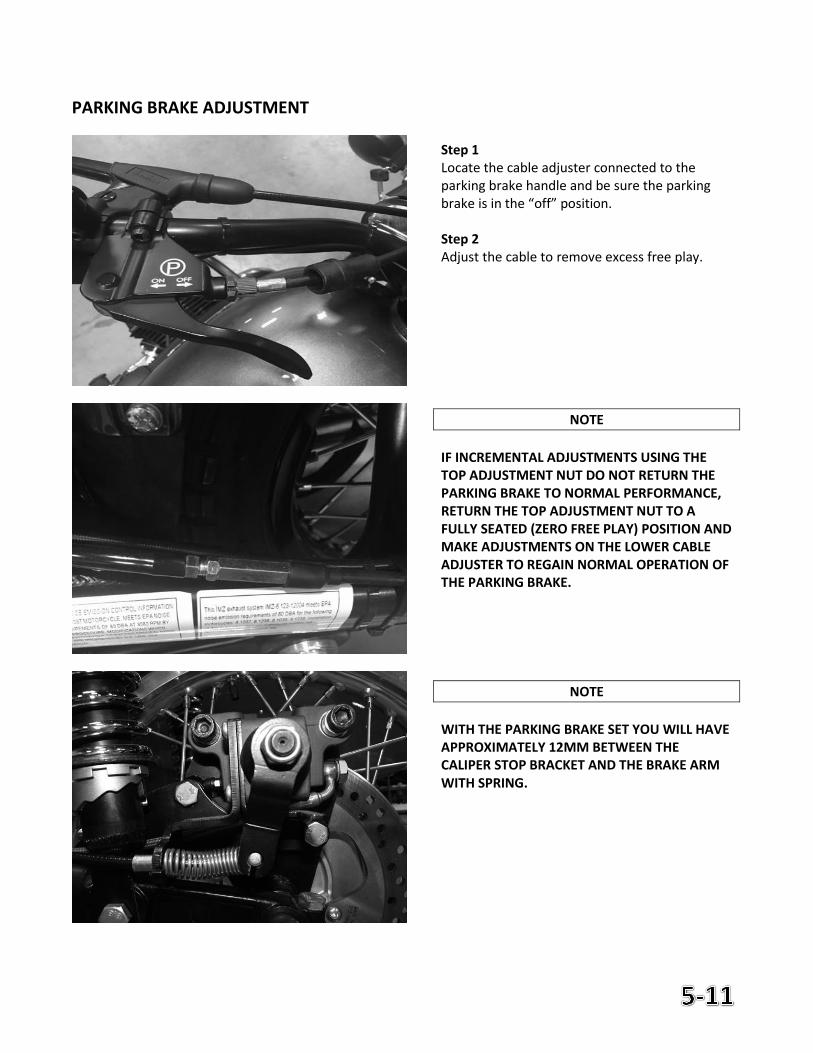
PARKING BRAKE ADJUSTMENT
Step 1 Locate the cable adjuster connected to the parking brake handle and be sure the parking brake is in the “off” position. Step 2 Adjust the cable to remove excess free play.
NOTE
IF INCREMENTAL ADJUSTMENTS USING THE TOP ADJUSTMENT NUT DO NOT RETURN THE PARKING BRAKE TO NORMAL PERFORMANCE, RETURN THE TOP ADJUSTMENT NUT TO A FULLY SEATED (ZERO FREE PLAY) POSITION AND MAKE ADJUSTMENTS ON THE LOWER CABLE ADJUSTER TO REGAIN NORMAL OPERATION OF THE PARKING BRAKE.
NOTE
WITH THE PARKING BRAKE SET YOU WILL HAVE APPROXIMATELY 12MM BETWEEN THE CALIPER STOP BRACKET AND THE BRAKE ARM WITH SPRING.
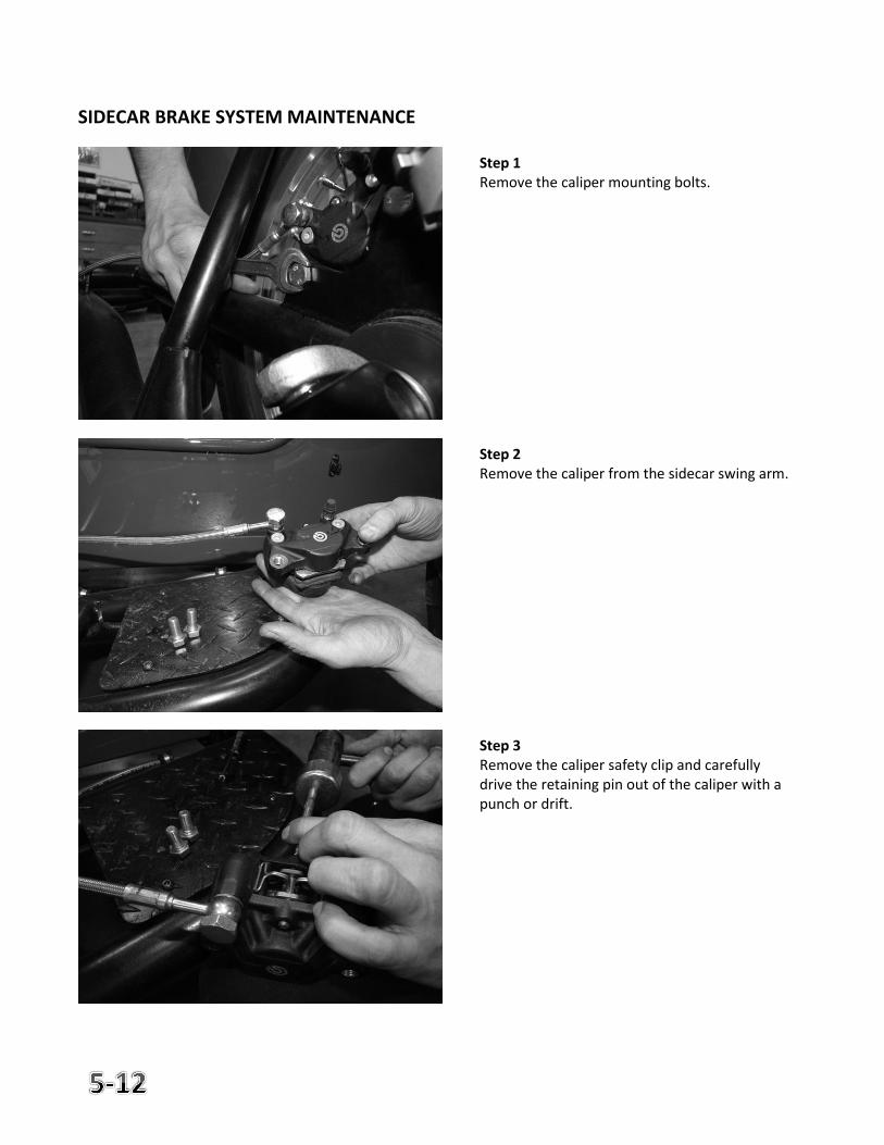
SIDECAR BRAKE SYSTEM MAINTENANCE
Step 1 Remove the caliper mounting bolts. Step 2 Remove the caliper from the sidecar swing arm. Step 3 Remove the caliper safety clip and carefully drive the retaining pin out of the caliper with a punch or drift.
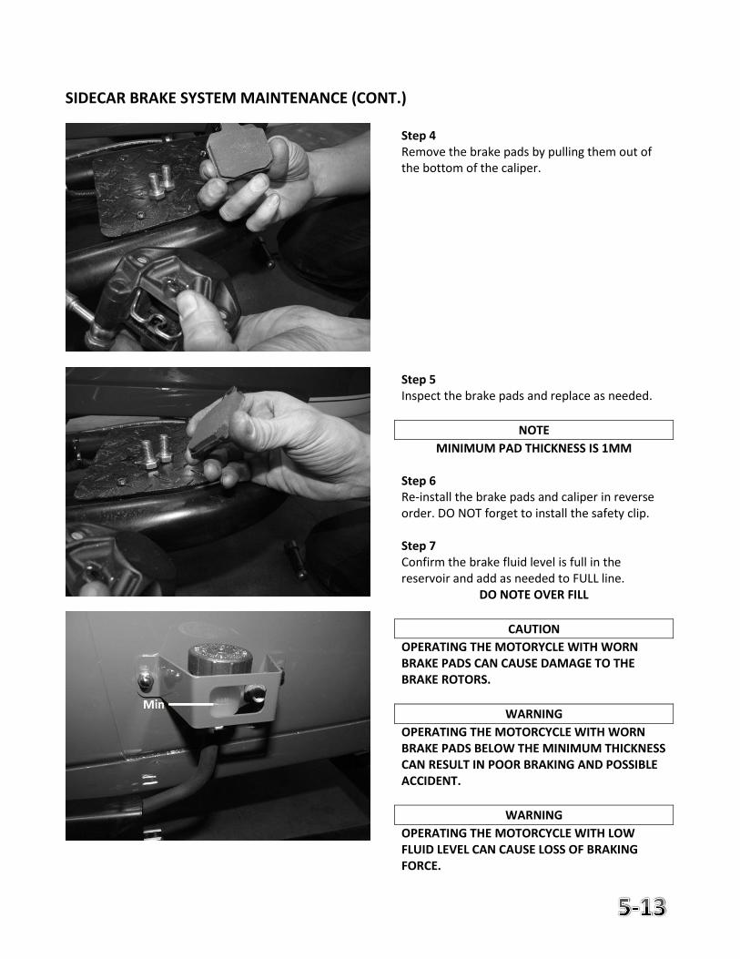
SIDECAR BRAKE SYSTEM MAINTENANCE (CONT.)
Step 4 Remove the brake pads by pulling them out of the bottom of the caliper. Step 5 Inspect the brake pads and replace as needed.
NOTE
MINIMUM PAD THICKNESS IS 1MM
Step 6 Re-install the brake pads and caliper in reverse order. DO NOT forget to install the safety clip. Step 7 Confirm the brake fluid level is full in the reservoir and add as needed to FULL line.
DO NOTE OVER FILL
CAUTION
OPERATING THE MOTORYCLE WITH WORN BRAKE PADS CAN CAUSE DAMAGE TO THE BRAKE ROTORS.
WARNING
OPERATING THE MOTORCYCLE WITH WORN BRAKE PADS BELOW THE MINIMUM THICKNESS CAN RESULT IN POOR BRAKING AND POSSIBLE ACCIDENT.
WARNING
OPERATING THE MOTORCYCLE WITH LOW FLUID LEVEL CAN CAUSE LOSS OF BRAKING FORCE.
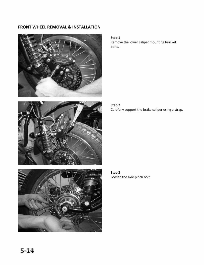
FRONT WHEEL REMOVAL & INSTALLATION
Step 1 Remove the lower caliper mounting bracket bolts. Step 2 Carefully support the brake caliper using a strap. Step 3 Loosen the axle pinch bolt.
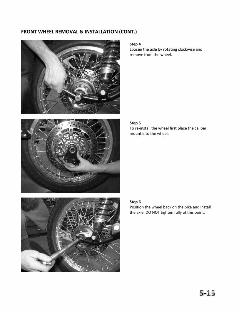
FRONT WHEEL REMOVAL & INSTALLATION (CONT.)
Step 4 Loosen the axle by rotating clockwise and remove from the wheel. Step 5 To re-install the wheel first place the caliper mount into the wheel. Step 6 Position the wheel back on the bike and install the axle. DO NOT tighten fully at this point.
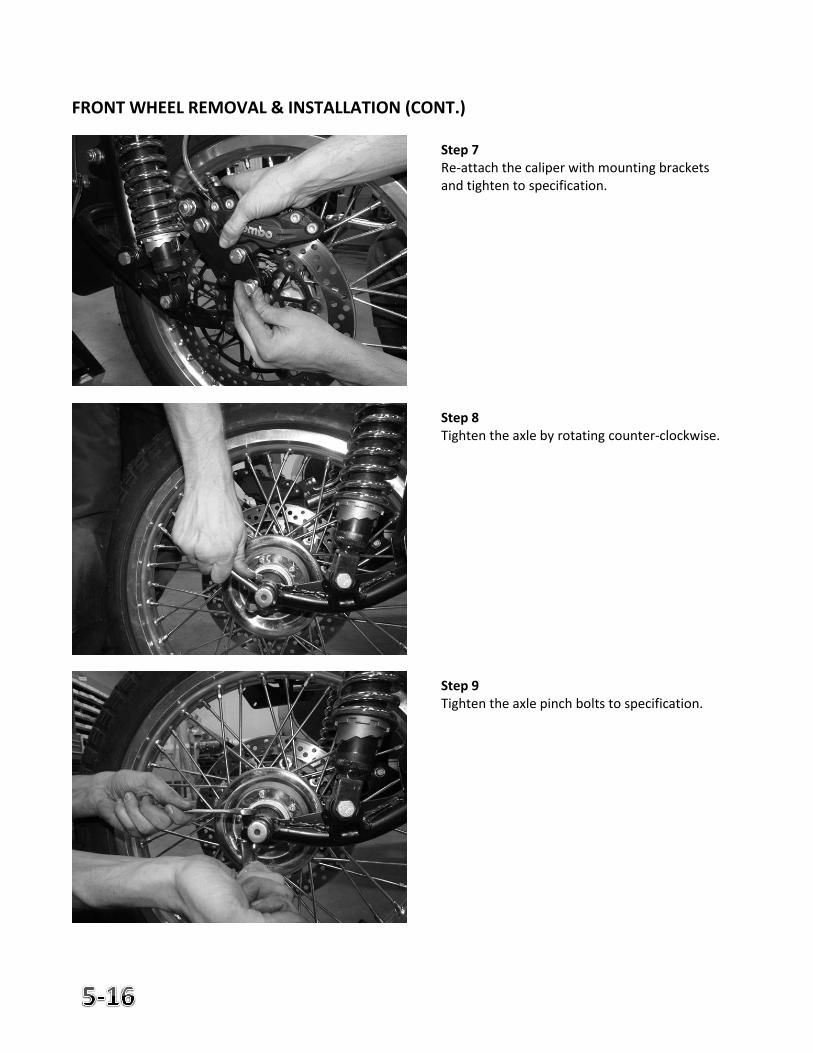
FRONT WHEEL REMOVAL & INSTALLATION (CONT.)
Step 7 Re-attach the caliper with mounting brackets and tighten to specification. Step 8 Tighten the axle by rotating counter-clockwise. Step 9 Tighten the axle pinch bolts to specification.
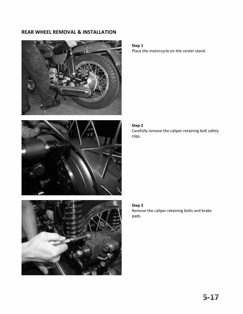
REAR WHEEL REMOVAL & INSTALLATION
Step 1 Place the motorcycle on the center stand. Step 2 Carefully remove the caliper retaining bolt safety clips. Step 3 Remove the caliper retaining bolts and brake pads.
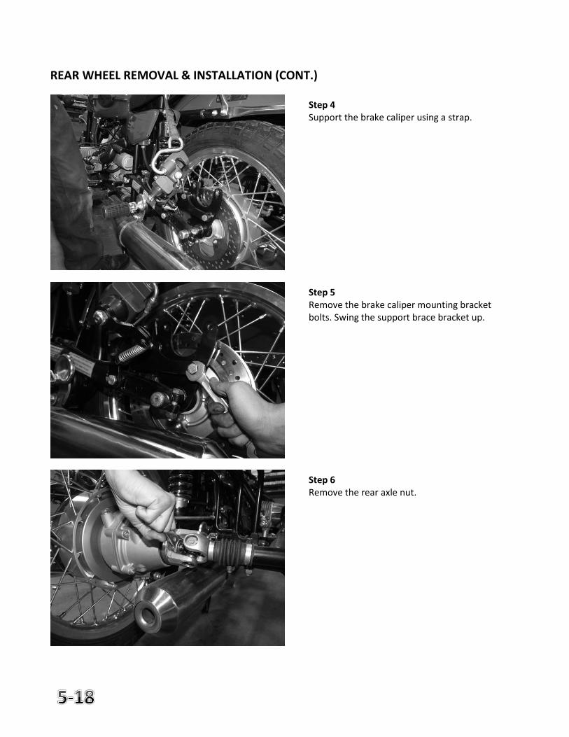
REAR WHEEL REMOVAL & INSTALLATION (CONT.)
Step 4 Support the brake caliper using a strap. Step 5 Remove the brake caliper mounting bracket bolts. Swing the support brace bracket up. Step 6 Remove the rear axle nut.
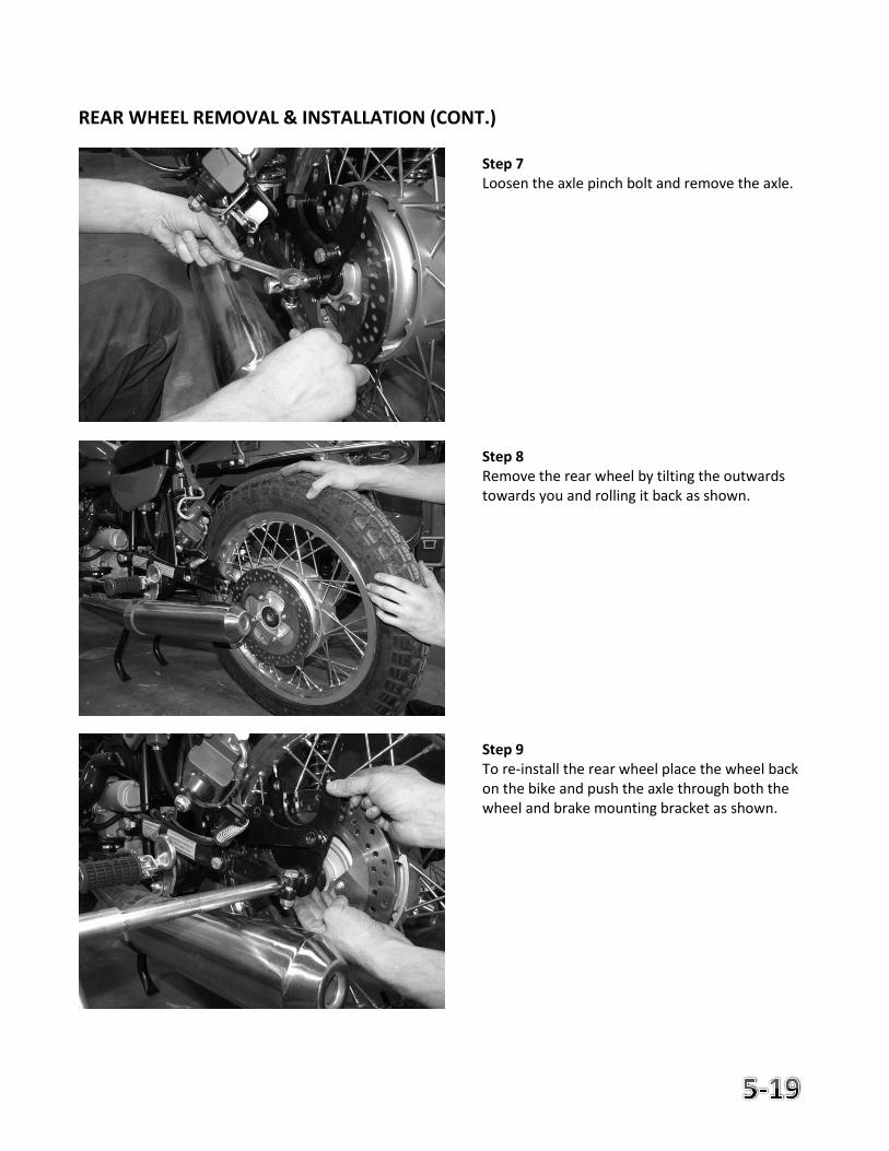
REAR WHEEL REMOVAL & INSTALLATION (CONT.)
Step 7 Loosen the axle pinch bolt and remove the axle. Step 8 Remove the rear wheel by tilting the outwards towards you and rolling it back as shown. Step 9 To re-install the rear wheel place the wheel back on the bike and push the axle through both the wheel and brake mounting bracket as shown.
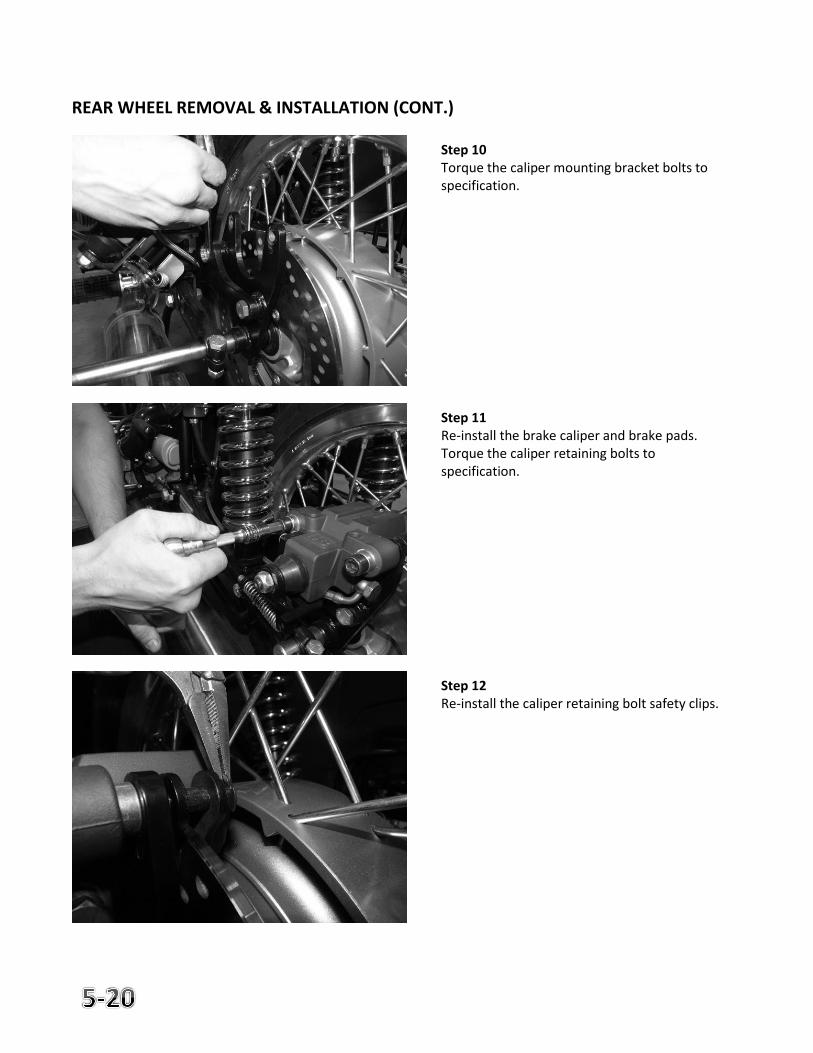
REAR WHEEL REMOVAL & INSTALLATION (CONT.)
Step 10 Torque the caliper mounting bracket bolts to specification. Step 11 Re-install the brake caliper and brake pads. Torque the caliper retaining bolts to specification. Step 12 Re-install the caliper retaining bolt safety clips.
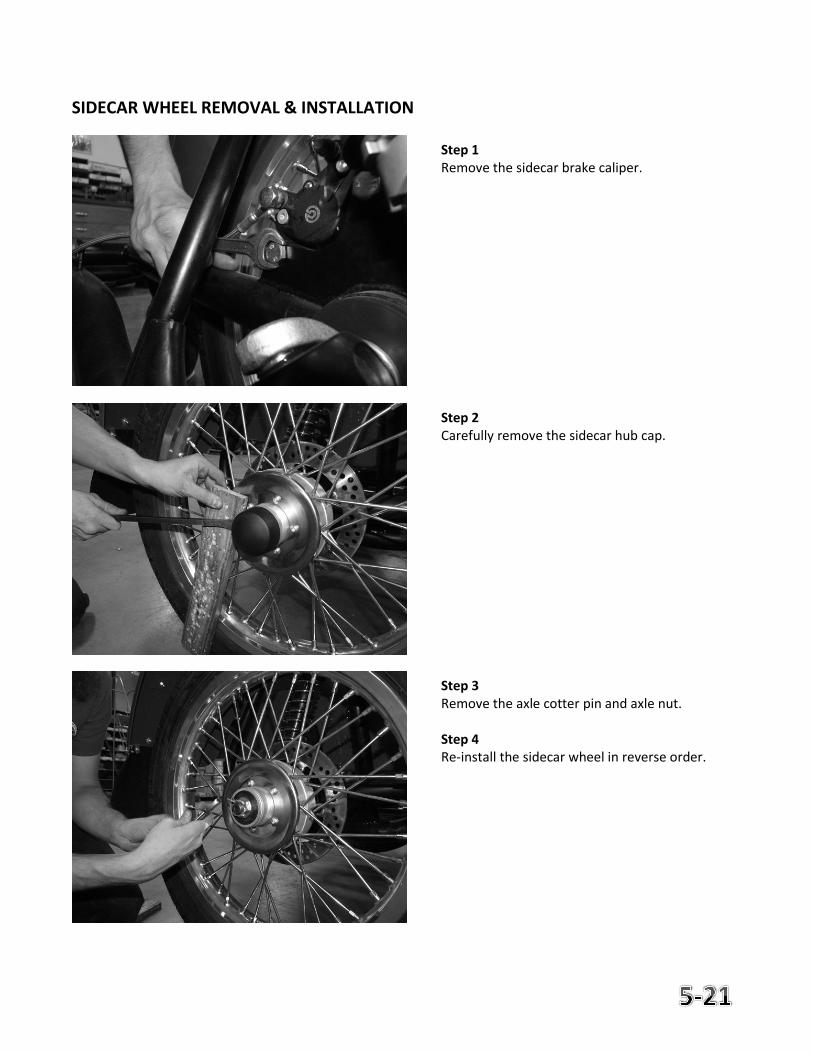
SIDECAR WHEEL REMOVAL & INSTALLATION
Step 1 Remove the sidecar brake caliper. Step 2 Carefully remove the sidecar hub cap. Step 3 Remove the axle cotter pin and axle nut. Step 4 Re-install the sidecar wheel in reverse order.
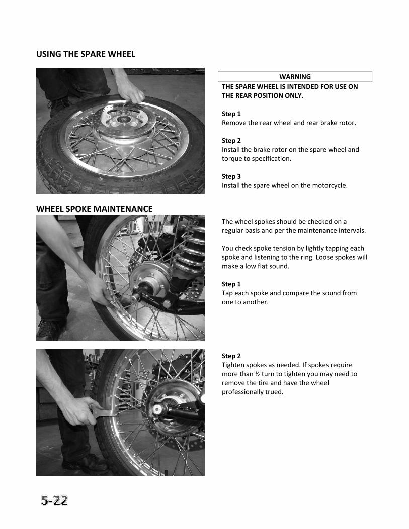
USING THE SPARE WHEEL
WHEEL SPOKE MAINTENANCE
WARNING
THE SPARE WHEEL IS INTENDED FOR USE ON THE REAR POSITION ONLY. Step 1 Remove the rear wheel and rear brake rotor. Step 2 Install the brake rotor on the spare wheel and torque to specification. Step 3 Install the spare wheel on the motorcycle. The wheel spokes should be checked on a regular basis and per the maintenance intervals. You check spoke tension by lightly tapping each spoke and listening to the ring. Loose spokes will make a low flat sound. Step 1 Tap each spoke and compare the sound from one to another. Step 2 Tighten spokes as needed. If spokes require more than ½ turn to tighten you may need to remove the tire and have the wheel professionally trued.
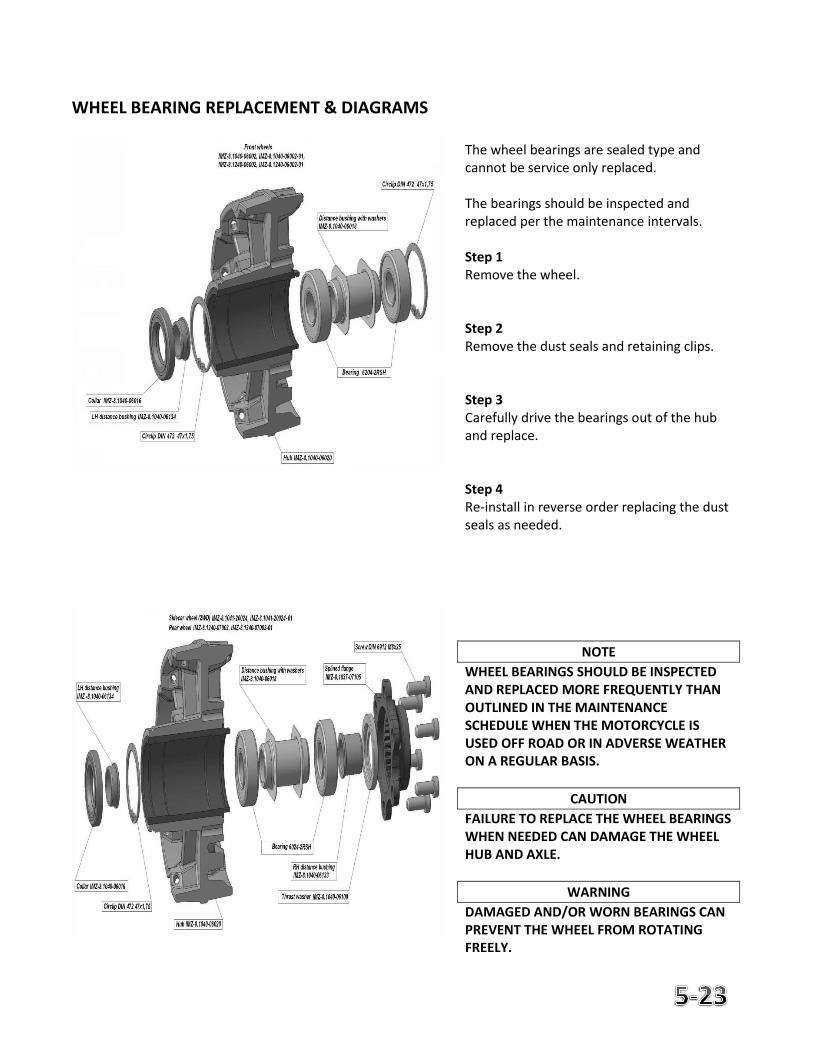
WHEEL BEARING REPLACEMENT & DIAGRAMS
The wheel bearings are sealed type and cannot be service only replaced. The bearings should be inspected and replaced per the maintenance intervals. Step 1 Remove the wheel. Step 2 Remove the dust seals and retaining clips. Step 3 Carefully drive the bearings out of the hub and replace. Step 4 Re-install in reverse order replacing the dust seals as needed.
NOTE
WHEEL BEARINGS SHOULD BE INSPECTED AND REPLACED MORE FREQUENTLY THAN OUTLINED IN THE MAINTENANCE SCHEDULE WHEN THE MOTORCYCLE IS USED OFF ROAD OR IN ADVERSE WEATHER ON A REGULAR BASIS.
CAUTION
FAILURE TO REPLACE THE WHEEL BEARINGS WHEN NEEDED CAN DAMAGE THE WHEEL HUB AND AXLE.
WARNING
DAMAGED AND/OR WORN BEARINGS CAN PREVENT THE WHEEL FROM ROTATING FREELY.
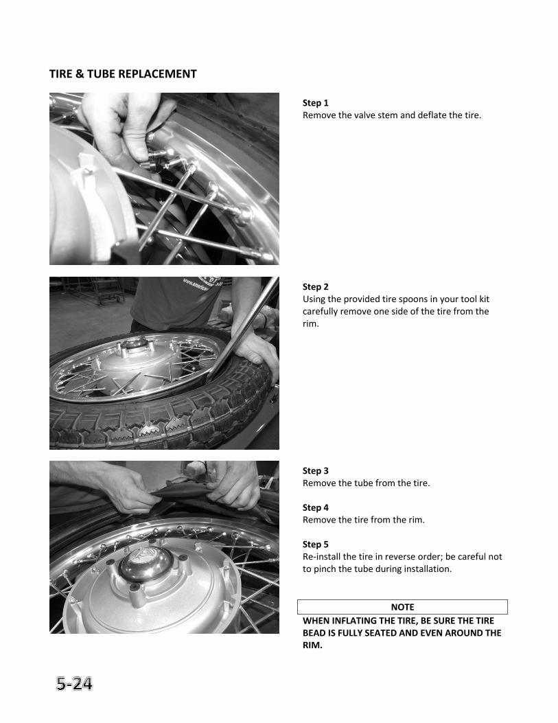
TIRE & TUBE REPLACEMENT
Step 1 Remove the valve stem and deflate the tire. Step 2 Using the provided tire spoons in your tool kit carefully remove one side of the tire from the rim. Step 3 Remove the tube from the tire. Step 4 Remove the tire from the rim. Step 5 Re-install the tire in reverse order; be careful not to pinch the tube during installation.
NOTE
WHEN INFLATING THE TIRE, BE SURE THE TIRE BEAD IS FULLY SEATED AND EVEN AROUND THE RIM.
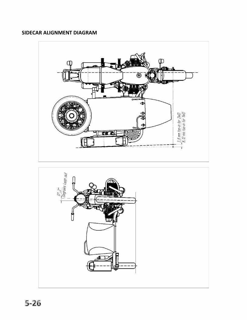
SIDECAR ALIGNMENT
The sidecar should be installed in a definite position relative to the motorcycle. The position is determined by the camber and toe-in of the motorcycle and the side car wheels. An incorrectly aligned side car will drag the motorcycle to either side and cause extensive tire wear. If the motorcycle is not stable on the road or is difficult to steer, check the alignment. Checking and measuring the alignment should be done on level ground. Check toe-in of the motorcycle and the side car wheels with two straight bars applied to the side faces of the wheels just below the ax les. The toe-in should be 3 to 8mm (2wd models) or 8 to 12mm (1wd models) at the front wheel. When adjusting, unbolt the top of the strut legs fastening the side car to the motorcycle, loosen the bolt clamping the lower rear bracket, and adjust the position of the bracket relative to the rear tube of the side car frame to obtain necessary toe-in of the wheels. Tighten up the bolt fastening the bracket, adjust the length of the strut legs and secure them with bolts. Check the lean-out of the motorcycle using a level gauge or protractor with a plumb bob and a ruler; standard lean-out is 1-2 degrees. Adjust the two inclined legs by screwing the forks in or out. When the lean-out is correct, the rider will remain vertical while riding on the local roads which may be slightly sloped to assist with water runoff. Check the toe-in while the motorcycle is running on the road. With the toe-in properly adjusted, the motorcycle will not pull to either side while running at normal road speed. If it pulls to the right, increase the toe-in, if it pulls to the left, decrease the toe-in.
CAUTION
DOUBLE CHECK FOR CORRECT TOE-IN BEFORE MAKING ANY CHANGE TO LEAN-OUT.
SIDECAR ALIGNMENT DIAGRAM
6. Electrical
Page
Lamp & Bulb Replacement 6-2 Battery Maintenance & Replacement 6-6 Fuse & Relay Locations 6-9 Sidecar Fuse & Relay Locations 6-10 Starter 6-11 Alternator 6-11 ECU Data Port 6-11
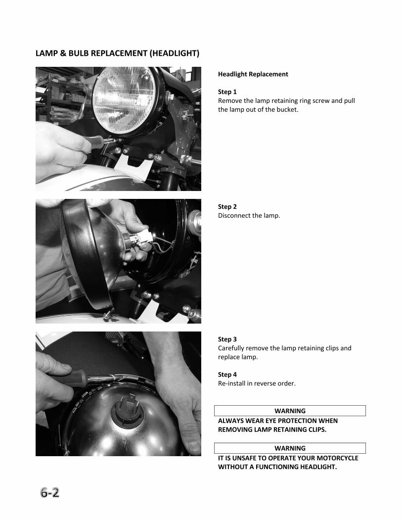
LAMP & BULB REPLACEMENT (HEADLIGHT)
Headlight Replacement Step 1 Remove the lamp retaining ring screw and pull the lamp out of the bucket. Step 2 Disconnect the lamp. Step 3 Carefully remove the lamp retaining clips and replace lamp. Step 4 Re-install in reverse order.
WARNING
ALWAYS WEAR EYE PROTECTION WHEN REMOVING LAMP RETAINING CLIPS.
WARNING
IT IS UNSAFE TO OPERATE YOUR MOTORCYCLE WITHOUT A FUNCTIONING HEADLIGHT.
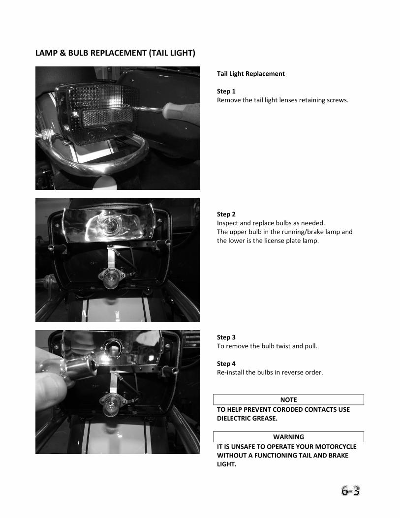
LAMP & BULB REPLACEMENT (TAIL LIGHT)
Tail Light Replacement Step 1 Remove the tail light lenses retaining screws. Step 2 Inspect and replace bulbs as needed. The upper bulb in the running/brake lamp and the lower is the license plate lamp. Step 3 To remove the bulb twist and pull. Step 4 Re-install the bulbs in reverse order.
NOTE
TO HELP PREVENT CORODED CONTACTS USE DIELECTRIC GREASE.
WARNING
IT IS UNSAFE TO OPERATE YOUR MOTORCYCLE WITHOUT A FUNCTIONING TAIL AND BRAKE LIGHT.
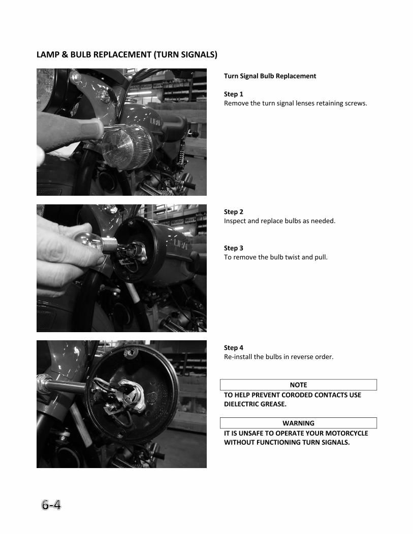
LAMP & BULB REPLACEMENT (TURN SIGNALS)
Turn Signal Bulb Replacement Step 1 Remove the turn signal lenses retaining screws. Step 2 Inspect and replace bulbs as needed. Step 3 To remove the bulb twist and pull. Step 4 Re-install the bulbs in reverse order.
NOTE
TO HELP PREVENT CORODED CONTACTS USE DIELECTRIC GREASE.
WARNING
IT IS UNSAFE TO OPERATE YOUR MOTORCYCLE WITHOUT FUNCTIONING TURN SIGNALS.
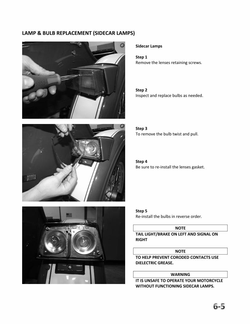
LAMP & BULB REPLACEMENT (SIDECAR LAMPS)
Sidecar Lamps Step 1 Remove the lenses retaining screws. Step 2 Inspect and replace bulbs as needed. Step 3 To remove the bulb twist and pull. Step 4 Be sure to re-install the lenses gasket. Step 5 Re-install the bulbs in reverse order.
NOTE
TAIL LIGHT/BRAKE ON LEFT AND SIGNAL ON RIGHT
NOTE
TO HELP PREVENT CORODED CONTACTS USE DIELECTRIC GREASE.
WARNING
IT IS UNSAFE TO OPERATE YOUR MOTORCYCLE WITHOUT FUNCTIONING SIDECAR LAMPS.
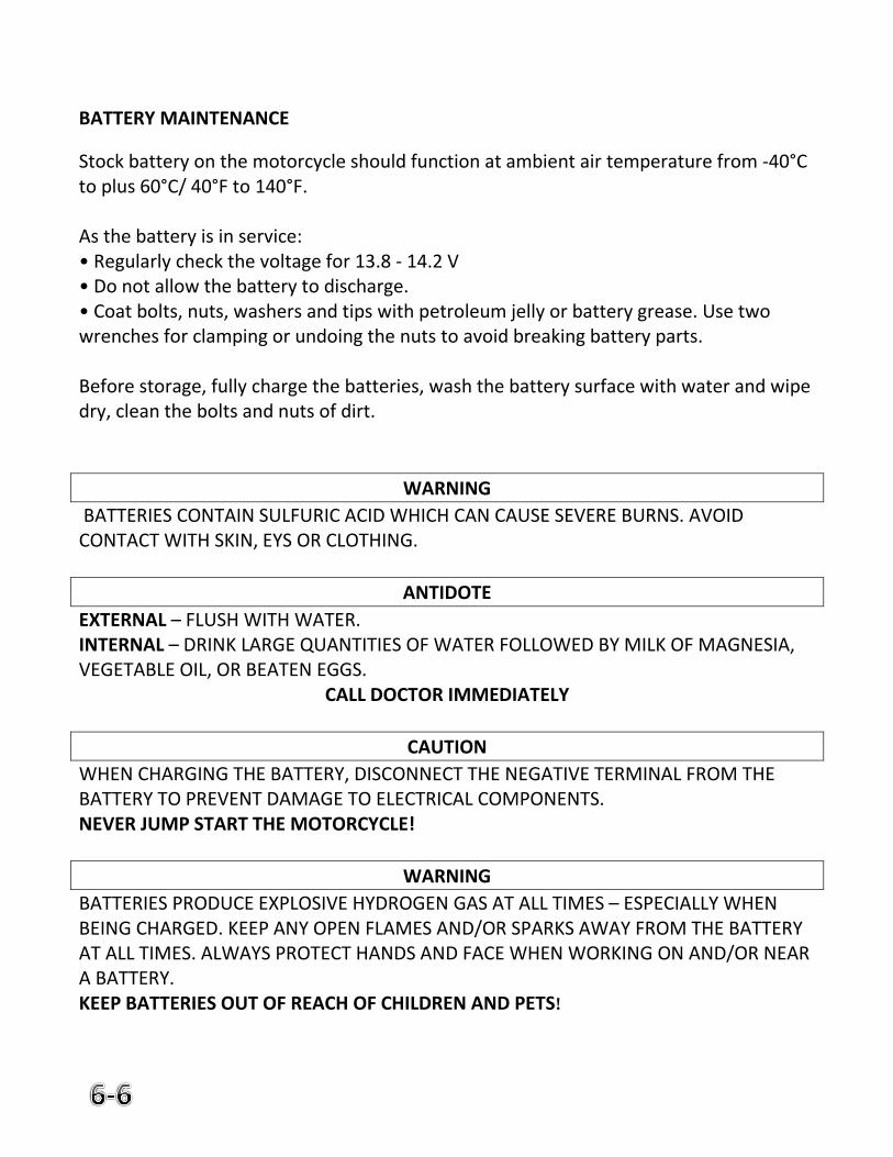
BATTERY MAINTENANCE
Stock battery on the motorcycle should function at ambient air temperature from -40°C to plus 60°C/ 40°F to 140°F. As the battery is in service: • Regularly check the voltage for 13.8 - 14.2 V • Do not allow the battery to discharge. • Coat bolts, nuts, washers and tips with petroleum jelly or battery grease. Use two wrenches for clamping or undoing the nuts to avoid breaking battery parts. Before storage, fully charge the batteries, wash the battery surface with water and wipe dry, clean the bolts and nuts of dirt.
WARNING
BATTERIES CONTAIN SULFURIC ACID WHICH CAN CAUSE SEVERE BURNS. AVOID CONTACT WITH SKIN, EYS OR CLOTHING.
ANTIDOTE
EXTERNAL – FLUSH WITH WATER. INTERNAL – DRINK LARGE QUANTITIES OF WATER FOLLOWED BY MILK OF MAGNESIA, VEGETABLE OIL, OR BEATEN EGGS.
CALL DOCTOR IMMEDIATELY
CAUTION
WHEN CHARGING THE BATTERY, DISCONNECT THE NEGATIVE TERMINAL FROM THE BATTERY TO PREVENT DAMAGE TO ELECTRICAL COMPONENTS. NEVER JUMP START THE MOTORCYCLE!
WARNING
BATTERIES PRODUCE EXPLOSIVE HYDROGEN GAS AT ALL TIMES – ESPECIALLY WHEN BEING CHARGED. KEEP ANY OPEN FLAMES AND/OR SPARKS AWAY FROM THE BATTERY AT ALL TIMES. ALWAYS PROTECT HANDS AND FACE WHEN WORKING ON AND/OR NEAR A BATTERY. KEEP BATTERIES OUT OF REACH OF CHILDREN AND PETS!
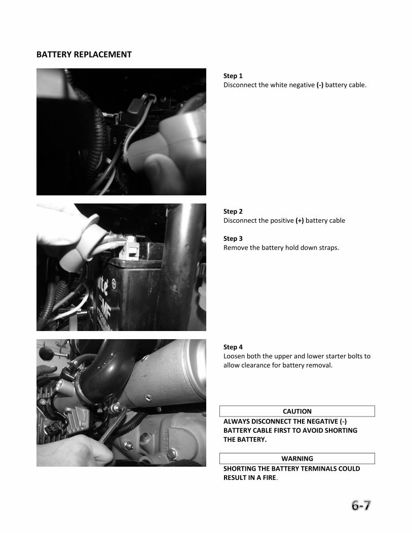
BATTERY REPLACEMENT
Step 1 Disconnect the white negative (-) battery cable. Step 2 Disconnect the positive (+) battery cable Step 3 Remove the battery hold down straps. Step 4 Loosen both the upper and lower starter bolts to allow clearance for battery removal.
CAUTION
ALWAYS DISCONNECT THE NEGATIVE (-) BATTERY CABLE FIRST TO AVOID SHORTING THE BATTERY.
WARNING
SHORTING THE BATTERY TERMINALS COULD RESULT IN A FIRE.
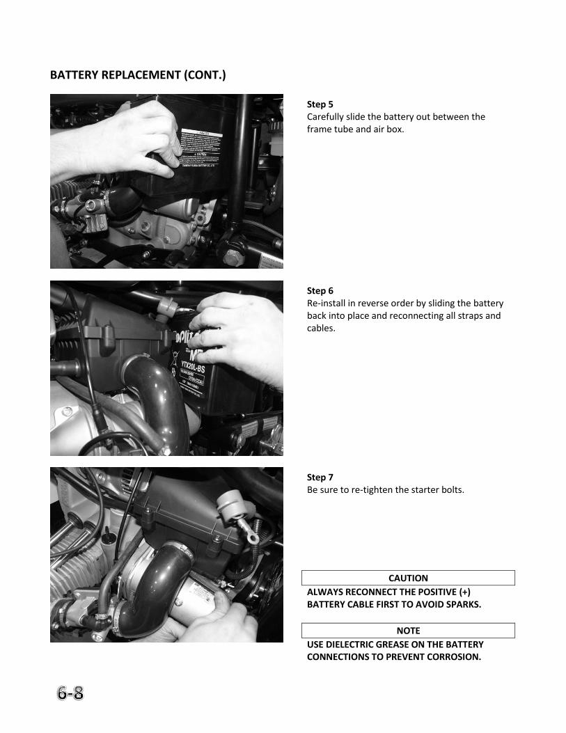
BATTERY REPLACEMENT (CONT.)
Step 5 Carefully slide the battery out between the frame tube and air box. Step 6 Re-install in reverse order by sliding the battery back into place and reconnecting all straps and cables. Step 7 Be sure to re-tighten the starter bolts.
CAUTION
ALWAYS RECONNECT THE POSITIVE (+) BATTERY CABLE FIRST TO AVOID SPARKS.
NOTE
USE DIELECTRIC GREASE ON THE BATTERY CONNECTIONS TO PREVENT CORROSION.
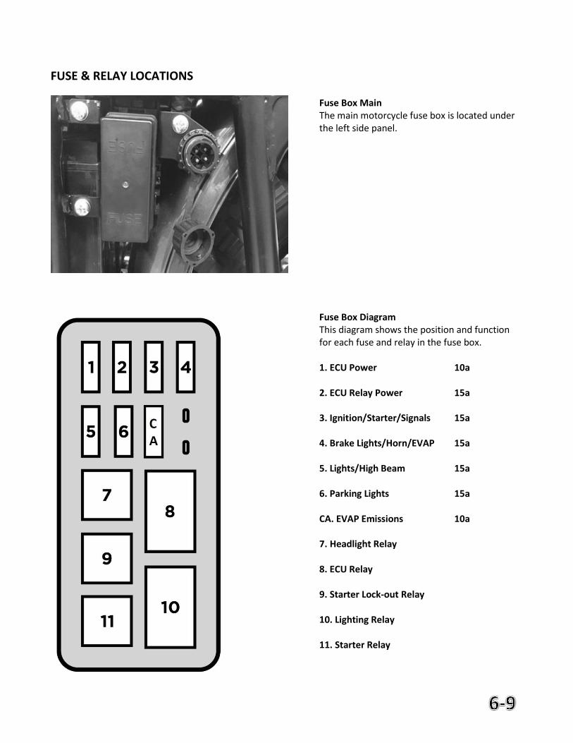
FUSE & RELAY LOCATIONS
Fuse Box Main The main motorcycle fuse box is located under the left side panel. Fuse Box Diagram This diagram shows the position and function for each fuse and relay in the fuse box. 1. ECU Power 10a 2. ECU Relay Power 15a 3. Ignition/Starter/Signals 15a 4. Brake Lights/Horn/EVAP 15a 5. Lights/High Beam 15a 6. Parking Lights 15a CA. EVAP Emissions 10a 7. Headlight Relay 8. ECU Relay 9. Starter Lock-out Relay 10. Lighting Relay 11. Starter Relay
FUSE & RELAY LOCATIONS (CONT.)
SIDECAR FUSE & RELAY LOCATIONS
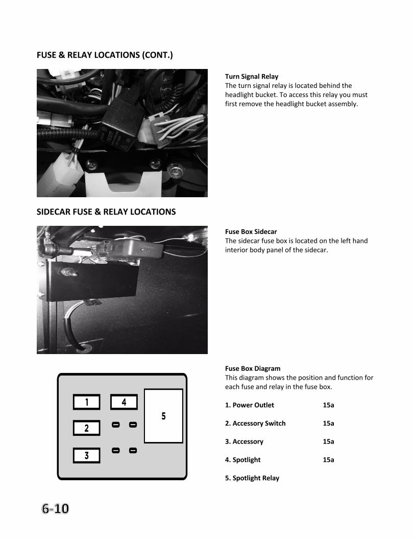
Turn Signal Relay The turn signal relay is located behind the headlight bucket. To access this relay you must first remove the headlight bucket assembly. Fuse Box Sidecar The sidecar fuse box is located on the left hand interior body panel of the sidecar. Fuse Box Diagram This diagram shows the position and function for each fuse and relay in the fuse box. 1. Power Outlet 15a 2. Accessory Switch 15a 3. Accessory 15a 4. Spotlight 15a 5. Spotlight Relay
ELECTRIC STARTER
The starter must provide 300-400 rpm to start the engine and requires a well maintained battery. If battery is below required voltage the electric starter may not operate efficiently. If the battery becomes low you may need to use the kick starter. ALTERNATOR
This motorcycle is equipped with a Denso Alternator. Specifications: Rated Voltage 12V Rated Output 40A, 480W Peak Output 560W @ 14V Testing the Alternator on the Motorcycle If no test bench is available, check the output of the alternator with the engine running.
Connect the voltmeter to positive and negative terminals of the storage battery
Start the engine
While starting the voltage will drop to as low as 9.5 V
At 3500-4000 rpm output voltage should be 13.5-14.5 VDC
In the course of daily inspection, check the fastening of wires to the alternator terminals and fastening of the alternator on the engine crankcase. ECU DATA PORT
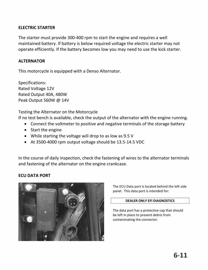
The ECU Data port is located behind the left side panel. This data port is intended for:
DEALER ONLY EFI DIAGNOSTICS
The data port has a protective cap that should be left in place to prevent debris from contaminating the connector.
7. EFI Troubleshooting
Page
Engine Management (MIL Blink Codes) 7-2 Service Notes 7-4
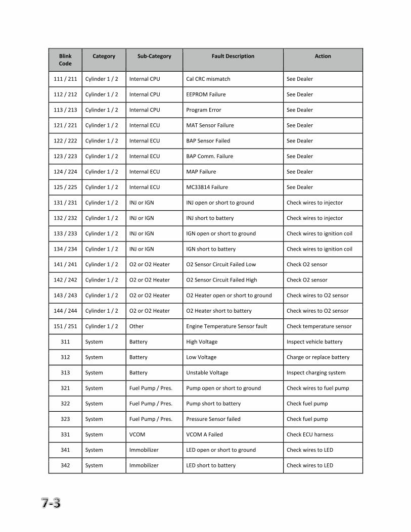
URAL ENGINE MANAGEMENT SYSTEM BLINK DIAGNOSTICS Introduction
A basic blink code system has been implemented on the Ural EFI bikes to aid EMS (Engine Management System) diagnostics without the need for an additional computer diagnostic tool, greatly helping the user when during travels. When activated, the MIL (malfunction indicator lamp) blinks out a code sequence relating to the fault. This document is intended as a quick reference guide as supplemental information to the EMS Service Manual. Operation When the MIL is continuously lit with the key on, an EMS fault has occurred. With the key on and engine off, toggle the kill switch three times within a two second timeframe to initiate the blink sequence. Three changes are required, not three complete kill-run cycles. For example, if the switch is in engine kill state, the sequence would be “Kill -> Run -> Kill -> Run” with the ‘->’ indicating a flick of the switch. The MIL will now blink a code sequence corresponding with the EMS’s diagnosed fault. Each code has a three digit sequence, with each digit having a value of 1-5. A short pause occurs between individual digits, while a long pause between repeating the code or displaying the next code, depending on the number of fault events. To identify the fault, initiate the blink sequence, and count out blinks for each of the three digits. Writing down the pattern helps. The light will blink on half second intervals for each digit. Between each digit, a one second pause will occur. Between each blink code, or the repetition of the code if a single fault is present, a three second pause exists. When a fault presents a specific component on the vehicle system, the component must be inspected, along with electrical connections and harness components leading up to the component. This will aid in diagnosing and fixing the problem. The blink sequence will continue to repeat until the function is deactivated. To deactivate the feature, toggle the kill switch three times within a two second time-frame, the same as to activate the feature. Fault Category
The first digit is used to indicate the category of fault. This helps to identify if the problem is specific to one ECU or to the vehicle as a whole. These categories are defined as follows:
First Digit Value
Category Description
1 Cylinder 1 Faults Faults specific to the left EMS
2 Cylinder 2 Faults Faults specific to the right EMS
3 System Faults Vehicle level EMS faults
Blink Code
Category Sub-Category Fault Description Action
111 / 211 Cylinder 1 / 2 Internal CPU Cal CRC mismatch See Dealer
112 / 212 Cylinder 1 / 2 Internal CPU EEPROM Failure See Dealer
113 / 213 Cylinder 1 / 2 Internal CPU Program Error See Dealer
121 / 221 Cylinder 1 / 2 Internal ECU MAT Sensor Failure See Dealer
122 / 222 Cylinder 1 / 2 Internal ECU BAP Sensor Failed See Dealer
123 / 223 Cylinder 1 / 2 Internal ECU BAP Comm. Failure See Dealer
124 / 224 Cylinder 1 / 2 Internal ECU MAP Failure See Dealer
125 / 225 Cylinder 1 / 2 Internal ECU MC33814 Failure See Dealer
131 / 231 Cylinder 1 / 2 INJ or IGN INJ open or short to ground Check wires to injector
132 / 232 Cylinder 1 / 2 INJ or IGN INJ short to battery Check wires to injector
133 / 233 Cylinder 1 / 2 INJ or IGN IGN open or short to ground Check wires to ignition coil
134 / 234 Cylinder 1 / 2 INJ or IGN IGN short to battery Check wires to ignition coil
141 / 241 Cylinder 1 / 2 O2 or O2 Heater O2 Sensor Circuit Failed Low Check O2 sensor
142 / 242 Cylinder 1 / 2 O2 or O2 Heater O2 Sensor Circuit Failed High Check O2 sensor
143 / 243 Cylinder 1 / 2 O2 or O2 Heater O2 Heater open or short to ground Check wires to O2 sensor
144 / 244 Cylinder 1 / 2 O2 or O2 Heater O2 Heater short to battery Check wires to O2 sensor
151 / 251 Cylinder 1 / 2 Other Engine Temperature Sensor fault Check temperature sensor
311 System Battery High Voltage Inspect vehicle battery
312 System Battery Low Voltage Charge or replace battery
313 System Battery Unstable Voltage Inspect charging system
321 System Fuel Pump / Pres. Pump open or short to ground Check wires to fuel pump
322 System Fuel Pump / Pres. Pump short to battery Check fuel pump
323 System Fuel Pump / Pres. Pressure Sensor failed Check fuel pump
331 System VCOM VCOM A Failed Check ECU harness
341 System Immobilizer LED open or short to ground Check wires to LED
342 System Immobilizer LED short to battery Check wires to LED
SERVICE NOTES
8. Warranty Information
Page
Warranty Agreement 8-2
Warranty Disclaimers 8-3
Limited Emissions Warranty 8-5
California Emissions Statement 8-7
Extended Warranty Reporting Safety Defects
8-8 8-8
Reporting Safety Defects 8-9
URAL MOTORCYCLES LIMITED WARRANTY Ural Motorcycles warrants to the first retail purchaser of the URAL motorcycle from an authorized dealer and each subsequent owner that the motorcycle is free from defects in materials and workmanship for the period stated below.
To Qualify For This Warranty • The URAL® motorcycle must be purchased from a dealer within the United States or Canada who is
authorized by Ural Motorcycles to sell motorcycles (see www.imz-ural.com for a complete list of authorized dealers).
• Prior to delivery to the purchaser, the dealer who is authorized by Ural Motorcycles to sell motorcycles must perform the complete set-up and pre-delivery procedures.
Warranty Time Period for Current Model Year • Duration of Ural Motorcycles Limited Warranty is 24 months, starting with the earlier of (a) the date the
motorcycle is sold to the first retail purchaser and the warranty registration card is received by Ural Motorcycles, or (b) after 12 months in the selling dealer’s inventory.
• There is no mileage limitation. • Any unexpired portion of this limited warranty will be transferred to subsequent owners, upon the
resale of the motorcycle during the limited warranty period.
Warranty Coverage • To obtain warranty service, return your motorcycle at your expense within the limited warranty period
to an authorized Ural dealer. The authorized Ural dealer should be able to provide warranty service during normal business hours, depending upon the workload of the authorized dealer’s service department and the availability of necessary parts.
• Ural Motorcycles will repair or replace, at its options, any part (including parts of the emission control systems) that are found to be defective in material or workmanship under normal use for the applicable time period.
• In cases when warranty repair takes longer than 14 days, the warranty time period (see Warranty Time Period) is extended for the period of time required to complete the repairs, during which the motorcycle could not been ridden.
• Ural Motorcycles will reimburse non-URAL repair shops performing warranty repairs only if all the warranty processing and approval procedures are completely fulfilled and/or carried out according to Ural Motorcycles guidelines (see Warranty Claim Filing Procedures).
WARRANTY DISCLAIMERS LIMITATIONS & EXCLUSIONS Ural Motorcycles Disclaims Any Responsibility For:
• Loss of time due to warrantable issues and/or repairs. • Loss of use of motorcycle dues to warrantable repairs. • Transportation expenses including, but not limited to, towing and/or rentals. • Any other incidental or consequential damages and/or expenses.
THERE IS NO OTHER EXPRESSED WARRANTY (OTHER THAN THE SEPARATE EMISSIONS LIMITED WARRANTIES) ON THE MOTORCYCLE. Any implied warranty of merchantability or fitness for particular purpose is limited to the duration of the express warranty, or to the duration set forth in your state’s warranty statutes, whichever is shorter.
State Laws May Vary The previous listed limitations or exclusions may not apply to a motorcycle because of state laws. Some states may not allow limitations on how long an implied warranty lasts. Some states may not allow exclusion or limitation of incidental or consequential damages.
These Warranties Do Not Cover: 1. Failures or required services that is not due to a defect in material or factory workmanship 2. Parts or accessories affected or damaged by:
• Lack of required maintenance • Owner abuse • Accident and/or collision • Misuse • Normal wear • Neglect • Improper installation • Unsuitable use in an application for which the part was not designed • The incorporation or use of unsuitable attachments or parts • The unauthorized alteration of any part or system • Deterioration from the elements • Failure to follow running-in (break-in) procedure
3. Replacement of expendable maintenance items including, but not limited to:
Spark plugs
Filters
Lubricants
Compliance fittings (throttle body mounting flanges)
Tires
Gaskets
Fuel line
Fuses
Bulbs
Battery (after 1 year in service) 4. Paint and/or decal fading, peeling, blistering, chipping or rusting. 5. Surface rust or corrosion on the chassis and/or drivetrain.
The Following Activities Will VOID Warranty Coverage: • Any operation or use outside of that described in Owner’s Manual • Racing • Competition • Rental and/or other commercial use • Alteration of the odometer reading • Towing
Dealer’s Warranty Responsibilities: • Thoroughly check and road test new units before delivery. • Complete and send Warranty Registration and Card of Delivery to Ural Motorcycles within 3 business
days of the sale of motorcycle. • Accept all eligible motorcycles for warranty service regardless of selling dealer. • Keep records of all warranty work. • Attend service schools and annual dealer meetings as provided by Ural Motorcycles. • Submit warranty claims to Ural Motorcycles within 10 business days of the repair date. • Send failed parts and/or parts assemblies for an inspection to Ural Motorcycles within 3 (three) business
days upon Ural Motorcycle’s request at Ural Motorcycles shipping expense. • Provide digital pictures of failed and/or defective parts and assemblies with all claims.
Owner’s Warranty Responsibilities: • As the owner of Ural motorcycle, you are responsible for the performance of the required maintenance
listed in your owner’s manual. URAL recommends that you retain all receipts covering maintenance on your motorcycle, but URAL cannot deny warranty solely for the lack of receipts or for your failure to ensure the performance of all scheduled maintenance.
You are responsible for presenting your motorcycle to an URAL dealer as soon as a problem exists. The warranty repairs should be completed in a reasonable amount of time not to exceed 30 (thirty) days.
As the motorcycle owner, you should also be aware that URAL may deny you warranty coverage if your motorcycle or a part has failed due to abuse, neglect, improper maintenance or unapproved modifications.
LIMITED WARRANTY ON EMISSION CONTROL SYSTEM Ural Motorcycles, 14700 NE 95th St. Suite 102, Redmond, WA 98052, USA (hereinafter URAL) warrants that each new 2004 and later Ural motorcycle that includes as standard equipment a headlight, taillight and stoplight, and is street legal: A. is designed, built and equipped so as to conform at the time of initial retail purchase with all applicable regulations of the United States Environmental Protection Agency, and the California Air Resources Board; and B. is free from defects in material and workmanship which cause such motorcycle to fail to conform with applicable regulations of the United States Environmental Protection Agency or the California Air Resources Board for a period of use, depending on the engine displacement: of 30,000 kilometers (18,641 miles), if the motorcycle’s engine displacement is 280 cubic centimeters or greater or 5 (five) years from the date of initial retail delivery, whichever first occurs.
I. COVERAGE Warranty defects shall be remedied during customary business hours at any authorized URAL motorcycle dealer located within the United States of America in compliance with the Clean Air Act and applicable regulations of the United States Environmental Protection Agency and the California Air Resources Board. Any part or parts replaced under this warranty shall become the property of URAL. In the State of California only, emission related warranted parts are specifically defined by the state’s Emission Warranty Parts List.
These warranted parts are: Injectors
Electronic valves
Air box
Air cleaner element
Spark plug
Ignition coil
Ignition control valve module
Catalyst
Carbon absorber In the State of California only, Emission Control System emergency repairs, as provided for in the California Administrative Code, may be performed by other than an authorized URAL dealer. An emergency situation occurs when an authorized URAL dealer is not reasonably available, a part is not available within 30 (thirty) days, or a repair is not complete within 30 days. Any replacement part can be used in an emergency repair. URAL will reimburse the owner for the expenses, including diagnosis, not to exceed URAL’s suggested retail price for all warranted parts replaced and labor charges based on URAL’s recommended time allowance for the warranty repair and the geographically appropriate hourly labor rate. The owner may be required to keep receipts and failed parts in order to receive compensation.
II. LIMITATIONS This Emission Control System warranty shall not cover any of the following: A. Repair or replacement required as a result of (1) Accident (2) Misuse (3) Repairs improperly performed or replacements improperly installed (4) Use of replacement parts or accessories not conforming to URAL specifications which adversely affect performance and/or (5) Use in competitive racing or related events. A. Inspections, replacement of parts and other services and adjustments required for required maintenance
B. Any motorcycle on which the odometer mileage has been changed so that actual mileage cannot be readily determined.
III. LIMITED LIABILITY A. The liability of URAL under this Emission Control System Warranty is limited solely to the remedying of defects in material or workmanship by authorized URAL motorcycle dealers at its place of business during customary business hours. This warranty does not cover inconvenience or loss of use of the motorcycle or transportation of the motorcycle to or from the URAL dealer. URAL SHALL NOT BE LIABLE FOR ANY OTHER EXPENSES, LOSS OR DAMAGE, WHETHER DIRECT, INCIDENTAL, CONSEQUENTIAL OR EXEMPLARY ARISING IN CONNECTION WITH THE SALE OR USE OF OR INABILITY TO USE THE URAL MOTORCYCLE FOR ANY PURPOSE. SOME STATES DO NOT ALLOW THE EXCLUSION OR LIMITAION OF ANY INCIDENTAL OR CONSEQUESTIAL DAMAGES, SO THE ABOVE LIMITATIONS MAY NOT APPLY TO YOU. B. NO EXPRESS EMISSION CONTROL SYSTEM WARRANTY IS GIVEN BY URAL EXCEPT AS SPECIFICALLY SET FORTH HEREIN. ANY EMISSION CONTROL SYSTEM WARRANTY IMPLIED BY LAW, INCLUDING ANY WARRANTY OF MERCHANTABILITY OR FITNESS FOR A PARTICULAR PURPOSE, IS LIMITED TO THE EXPRESS EMISSION CONTROL SYSTEM WARRANTY TERMS STATED IN THIS WARRANTY. THE FOREGOING STATEMENT OF WARRANTY ARE EXCLUSIVE AND IN LIEU OF ALL OTHER REMEDIES. SOME STATES DO NOT ALLOW LIMITATIONS ON HOW LONG AN IMPLIED WARRANTY LASTS SO THE ABOVE LIMITATIONS MAY NOT APPLY TO YOU. C. No dealer is authorized to modify this URAL Limited Emission Control System Warranty.
IV. LEGAL RIGHTS THIS WARRANTY GIVES YOU SPECIFIC LEGAL RIGHTS, AND YOU MAY ALSO HAVE OTHER RIGHTS, WHICH VARY FROM STATE TO STATE.
V. THIS WARRANTY IS IN ADDITION TO THE URAL LIMITED MOTORCYCLE WARRANTY. VI. ADDITIONAL INFORMATION Any replacement part that is equivalent in performance and durability may be used in the performance of any maintenance or repairs. However, URAL is not liable for these parts. The owner is responsible for the performance of all required maintenance. Such maintenance may be performed at a service establishment or by any individual. The warranty period begins on the date the motorcycle is delivered to an ultimate purchaser.
CALIFORNIA EMISSION CONTROL SYSTEM WARRANTY STATEMENT Your Warranty Rights and Obligations The California Air Resources Board and Ural Motorcycles (hereinafter URAL) are pleased to explain the Emission Control System Warranty on your 2005 and later motorcycle. In California, new motor vehicles must be designed, built and equipped to meet the State’s stringent anti-smog standards. URAL must warrant the emission control system on your motorcycle for the periods of time listed below provided there has been no abuse, neglect or improper maintenance of your motorcycle. Your emission control system may include parts such as the carburetor, the ignition system, catalytic converter, and engine computer. Also included may be hoses, belts, connectors and other emission-related assemblies. Where a warrantable condition exists, URAL will repair your motorcycle at no cost to you including diagnosis, parts and labor.
Manufacturer’s Warranty Coverage Class III motorcycles (280cc and larger): for a period of use of five (5) years or 30,000 kilometers (18,641 miles), whichever first occurs. If an emission–related part on your motorcycle is defective, the part will be repaired or replaced by URAL. This is your emission control system DEFECTS WARRANTY.
Owner’s Warranty Responsibilities As the owner of Ural motorcycle, you are responsible for the performance of the required maintenance
listed in your owner’s manual. URAL recommends that you retain all receipts covering maintenance on your motorcycle, but URAL cannot deny warranty solely for the lack of receipts or for your failure to ensure the performance of all scheduled maintenance.
You are responsible for presenting your motorcycle to an URAL dealer as soon as a problem exists. The warranty repairs should be completed in a reasonable amount of time not to exceed 30 (thirty) days.
As the motorcycle owner, you should also be aware that URAL may deny you warranty coverage if your motorcycle or a part has failed due to abuse, neglect, improper maintenance or unapproved modifications.
If you have any questions regarding your warranty rights and responsibilities, you should contact Ural Motorcycles at 1-425-702-8484 or the California Air Resource Board at 9528 Telstar Avenue, El Monte, CA 91731.
EXTENDED WARRANTY To Qualify For The Ural Extended Warranty:
The URAL Extended Warranty must be purchased from a Dealer within the United States who is authorized by IMWA, Inc. to sell motorcycles.
The customer may purchase the Ural Extended Warranty, at any time, prior to the expiration of the initial factory two (2) year warranty.
Warranty Time Period Duration: One (1) years parts and labor.
Coverage begins the date after our standard two (2) year warranty ends.
Warranty Coverage The Ural extended warranty will follow the same terms and conditions of the current existing
Manufactures Warranty.
There is no mileage limitation.
SPARE PARTS AND ACCESSORIES WARRANTY
Ural Motorcycles provides limited warranty for spare parts and accessories for the following period of time starting from the time of purchase of the parts by a dealer or retail customer:
Engine – 12 months
Gearbox – 12 months
Final drive – 12 months
Alternator – 6 months
Starter – 6 months
EFI Components – 6 months
All other parts and accessories - 30 days The above applies ONLY in cases when a dealer or retail customer identifies defects before using parts and/or accessories or these defects are identified during use AND provided these parts and/or accessories have been properly installed by Ural Motorcycles or an authorized Ural dealer.
Irbit Motorworks of America, Inc. 14700 Ne 95th St. Suite 102
Redmond, WA 98052
REPORTING SAFETY DEFECTS If you believe that your vehicle has a defect which could cause a crash or could cause injury or death, you should immediately inform the National Highway Traffic Safety Administration (NHTSA) in addition to notifying Irbit Motorworks of America, Inc. If NHTSA receives similar complaints, it may open an investigation, and if it finds that a safety defect exists in a group of vehicles, it may order a recall and remedy campaign. However, NHTSA cannot become involved in any individual problems between you, your dealer, or Irbit Motorworks of America, Inc. To contact NHTSA you may either call the Auto Safety Hotline toll-free at:
1-800-424-9393 (366-0123 in Washington, DC area). Or write to:
NHTSA U.S. DEPARTMENT of TRANSPORTATION 400 7th Street SW, (NSA-11) Washington, DC 20590
You can also obtain other information about motor vehicle safety from the Hotline.
9. Emission Control Information
Page
Crankcase Emission Diagram 9-2
California Emission Control Diagram 9-3
Vehicle Emission Control Label 9-4
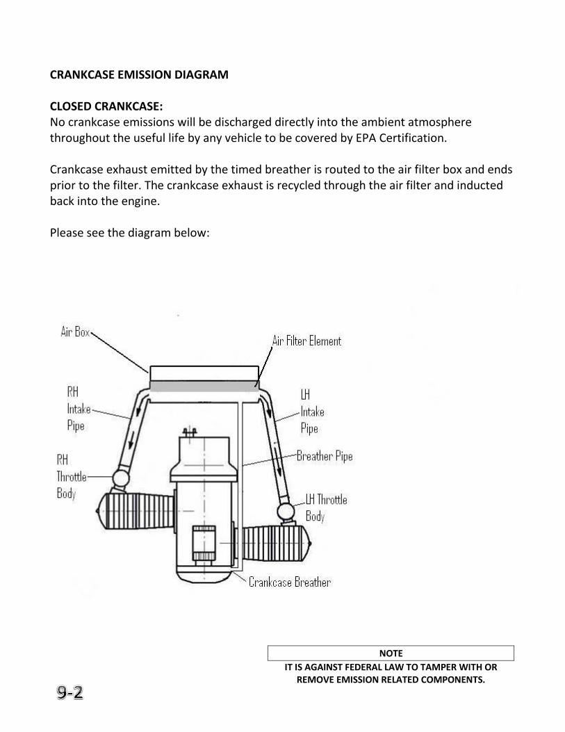
CRANKCASE EMISSION DIAGRAM CLOSED CRANKCASE: No crankcase emissions will be discharged directly into the ambient atmosphere throughout the useful life by any vehicle to be covered by EPA Certification. Crankcase exhaust emitted by the timed breather is routed to the air filter box and ends prior to the filter. The crankcase exhaust is recycled through the air filter and inducted back into the engine. Please see the diagram below:
NOTE
IT IS AGAINST FEDERAL LAW TO TAMPER WITH OR REMOVE EMISSION RELATED COMPONENTS.
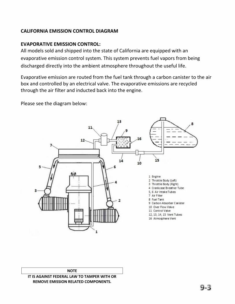
CALIFORNIA EMISSION CONTROL DIAGRAM EVAPORATIVE EMISSION CONTROL: All models sold and shipped into the state of California are equipped with an
evaporative emission control system. This system prevents fuel vapors from being
discharged directly into the ambient atmosphere throughout the useful life.
Evaporative emission are routed from the fuel tank through a carbon canister to the air box and controlled by an electrical valve. The evaporative emissions are recycled through the air filter and inducted back into the engine. Please see the diagram below:
NOTE
IT IS AGAINST FEDERAL LAW TO TAMPER WITH OR REMOVE EMISSION RELATED COMPONENTS.
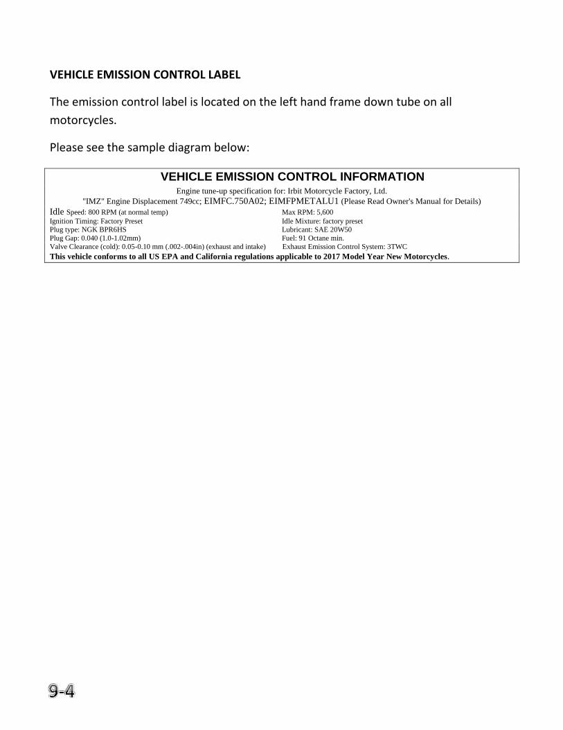
VEHICLE EMISSION CONTROL LABEL
The emission control label is located on the left hand frame down tube on all
motorcycles.
Please see the sample diagram below:
VEHICLE EMISSION CONTROL INFORMATION Engine tune-up specification for: Irbit Motorcycle Factory, Ltd.
"IMZ" Engine Displacement 749cc; EIMFC.750A02; EIMFPMETALU1 (Please Read Owner's Manual for Details)
Idle Speed: 800 RPM (at normal temp) Max RPM: 5,600
Ignition Timing: Factory Preset Idle Mixture: factory preset Plug type: NGK BPR6HS Lubricant: SAE 20W50
Plug Gap: 0.040 (1.0-1.02mm) Fuel: 91 Octane min.
Valve Clearance (cold): 0.05-0.10 mm (.002-.004in) (exhaust and intake) Exhaust Emission Control System: 3TWC
This vehicle conforms to all US EPA and California regulations applicable to 2017 Model Year New Motorcycles.
10. Owner's Documents
New Owner Form New Address Form
Training Rebate Form

Intentionally left blank
NEW OWNER FORM
To transfer warranty / register with Ural when purchasing a pre-owned Ural Motorcycle, please fill out this form and mail to the address below. This will ensure that you will benefit from any remaining warranty coverage.
Check here if you also want to receive newsletters and other promotional materials from Ural ** VEHICLE IDENTIFICATION NUMBER
NEW OWNER’S NAME _________________________________________________________________ ADDRESS ___________________________________________________________________________ ____________________________________________________________APT. NO. _______________ CITY _________________________________ STATE _________ ZIP CODE ____________-__________ PHONE NUMBER (_______)______________________ E-MAIL (optional) ____________________________________________________________________ DATE OF SALE ______/_____/________
MO DAY YEAR ODOMETER READING AT THE TIME OF TRANSFER ___________________ Purchased From _____________________________________________________________ City _____________________________ State ________ Zip Code ____________-_______ Mail this form to: Irbit Motorworks of America, Inc. Or fax to: (425) 250-6762 14700 NE 95th St., Suite 102 Redmond, WA 98052
**We never sell or rent your personal information to third parties unaffiliated with Ural.

Intentionally left blank
NEW ADDRESS FORM
If you move, please fill out the form and mail to the address below. This will insure that you continue to receive all correspondence from Irbit Motorworks of America. VEHICLE IDENTIFICATION NUMBER
___________________________________________________________________________
OWNER’S NAME_____________________________________________________________
OLD ADDRESS__________________________________________________________APT. NO.__________
CITY___________________________STATE___________________________ZIP CODE________________
MY NEW ADDRESS IS:
NEW ADDRESS_________________________________________________________APT. NO.__________
CITY___________________________STATE___________________________ZIP CODE________________
Mail this form to: Irbit Motorworks of America, Inc. Or fax to: (425) 250-6762 14700 NE 95th St., Suite 102 Redmond, WA 98052
**We never sell or rent your personal information to third parties unaffiliated with Ural.

Intentionally left blank
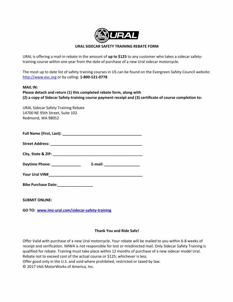
URAL SIDECAR SAFETY TRAINING REBATE FORM
URAL is offering a mail-in rebate in the amount of up to $125 to any customer who takes a sidecar safety-training course within one year from the date of purchase of a new Ural sidecar motorcycle. The most up to date list of safety training courses in US can be found on the Evergreen Safety Council website: http://www.esc.org or by calling: 1-800-521-0778 MAIL IN: Please detach and return (1) this completed rebate form, along with (2) a copy of Sidecar Safety-training course payment receipt and (3) certificate of course completion to: URAL Sidecar Safety Training Rebate 14700 NE 95th Street, Suite 102 Redmond, WA 98052 Full Name (First, Last): ______________________________________
Street Address: ____________________________________________
City, State & ZIP: ___________________________________________
Daytime Phone: ______________ E-mail: _________________ Your Ural VIN#_____________________________________________
Bike Purchase Date:_________________ SUBMIT ONLINE: GO TO: www.imz-ural.com/sidecar-safety-training
Thank You and Ride Safe!
Offer Valid with purchase of a new Ural motorcycle. Your rebate will be mailed to you within 6-8 weeks of receipt and verification. IMWA is not responsible for lost or misdirected mail. Only Sidecar Safety Training is qualified for rebate. Training must take place within 12 months of purchase of a new sidecar model Ural. Rebate not to exceed cost of the actual course or $125; whichever is less. Offer good only in the U.S. and void where prohibited, restricted or taxed by law. © 2017 Irbit MotorWorks of America, Inc.

Intentionally left blank
11. Schematics
Wiring Diagram