INTRODUCTION - Dayton Lamina
46
Transcript of INTRODUCTION - Dayton Lamina


INTRODUCTIONNEW LOOK,SAME TRADITION
LEMPCO is proud to introduce our new all-inclusive premium product catalog! This new catalog incorporates numerous upgrades to the brand, specifically product improvements, superior appearance and a new logo. With a bold and modern statement created for the brand, this catalog has been color-coded to easily locate product information.
As an internationally recognized manufacturer of guidance systems, LEMPCO has been servicing major industries, including canning, electronics, automotive, appliance, plastics, computer and specialty items, since 1918. Long recognized as the standard for excellence in the industry, and known by our extremely high quality and reliability, LEMPCO products are in demand worldwide.
Product ImProvementsAlways working hard to bring new solutions to customers, LEMPCO Ball Cages have been completely redesigned with several product improvements. The newly improved orbital staking enhances the reliability of ball bearing retention and prevents the loss of ball bearings during use. The Ball Cages are now black anodized to provide a protective hard coating which improves function and helps eliminate material flaking during operation. We have also added additional bearings on each retainer which increases bearing surface. These improved Ball Cages allow metal stampers to achieve high-speed press production with less frequent replacements, thus avoiding costly downtime. Overall, the orbital staking lowers the Ball Cage stress levels during production and improves the operational life cycle performance.
same Industry tradItIonsAlthough we have a new look, LEMPCO uses the same traditions we have always had. We pledge that all LEMPCO products, innovative or conventional, will be manufactured to the same high level of accuracy you have always known. To ensure you are receiving the high quality you expect from us, we stamp the LEMPCO name on every part we manufacture, which means satisfaction in terms of quality, dependability and service. The pride we have in our ability to perform and provide you with profitable production with our die sets and components is the foundation of our business.
customer satIsfactIonBacked by years of experience and a renewed commitment to our customers, LEMPCO understands customer needs and ensures cost-effective products and complete satisfaction. We recognize the value of maintaining relationships and can help meet the needs of quick deliveries, competitive prices and high quality parts. Our extensive LEMPCO distribution network, sales personnel and technical engineers will work closely with you to make sure your specifications are met.
cad fIlesLEMPCO component product line is now available on-line in 2D/3D CAD formats. To download the templates, visit our website at www.daytonlamina.com.
LEMPCO guidance systems are considered the quality standard in can making dies and tooling
systems worldwide. Find out how our new enhancements of our Retainer/Rotainer®
products can improve your performance.
New Ball Cage:
Orbital Stake
Old Ball Cage:Two-Point
Stake

1
PRODUCTS
the LEMPCO value ProPosItIon
♦ LEMPCO is a recognized leader in providing quality ball bearing components:
1. Rotainer® designed ball cage that minimizes tracking. 2. Precision Rotainer® and retainer that provides accuracy and repeatability in high speed applications. 3. Quality pins and bushings are made from 52100 tool steel and are precision ground.
♦ LEMPCO has a strong distribution network located around the world to service our valued customers.
qualIty ∙ dePendabIlIty ∙ servIce
sInce 1918
the Global standard WIth dIstrIbutors WorldWIde
Pins & Bushings – Inch ------------2 Engineering & Technical Data -------------13 Plain Bearing Bushings ---------------------18
Pins & Bushings – Metric -------20 Engineering Data ----------------------------28
Die Springs ---------------------------29 Accessories ------------------------------------38 Spring Cages, Spring Retainers
Specialty Items ---------------------40
2
For Ball Bearing applications
ROTaINeRs®
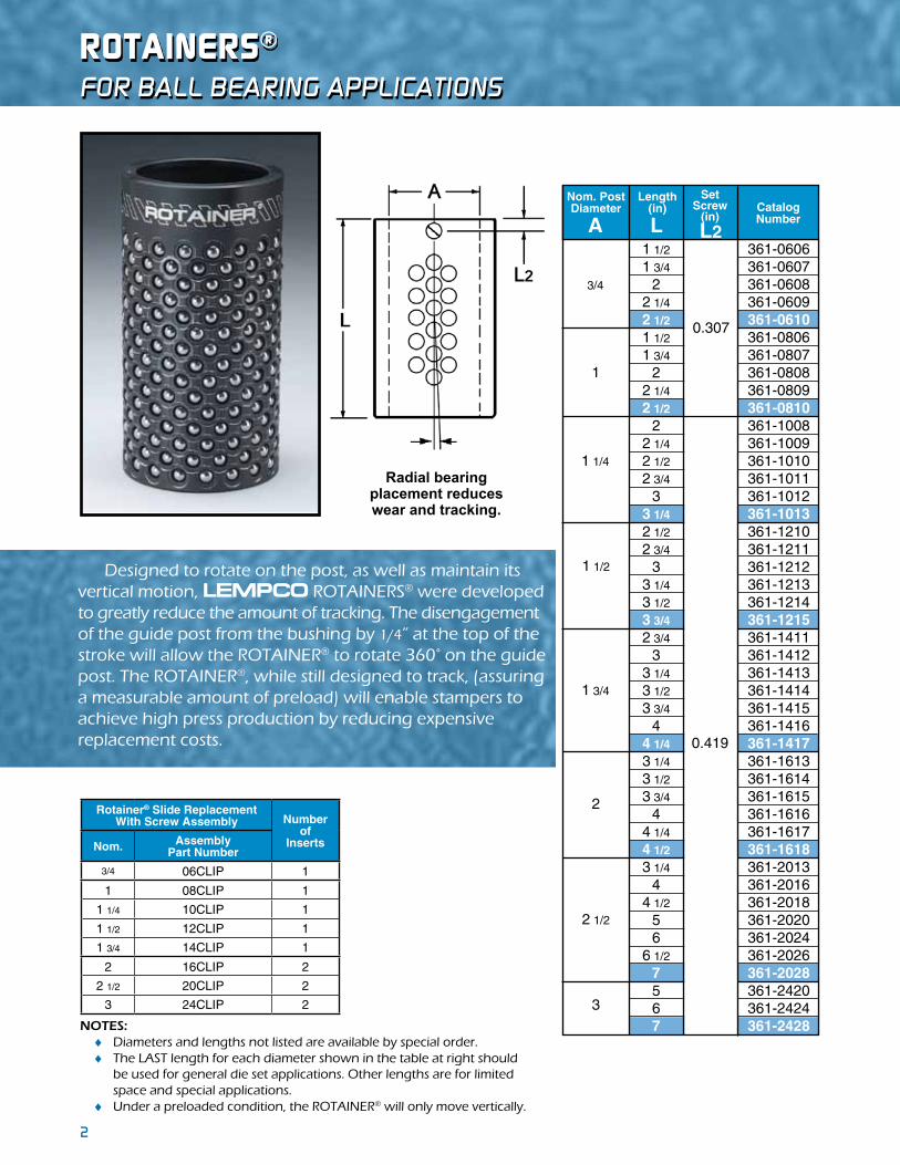
NOTES: ♦ Diameters and lengths not listed are available by special order. ♦ The LAST length for each diameter shown in the table at right should be used for general die set applications. Other lengths are for limited space and special applications. ♦ Under a preloaded condition, the ROTAINER® will only move vertically.
Designed to rotate on the post, as well as maintain its vertical motion, LEMPCO ROTAINERS® were developed to greatly reduce the amount of tracking. The disengagement of the guide post from the bushing by 1/4” at the top of the stroke will allow the ROTAINER® to rotate 360° on the guide post. The ROTAINER®, while still designed to track, (assuring a measurable amount of preload) will enable stampers to achieve high press production by reducing expensive replacement costs.
Radial bearing placement reduces wear and tracking.
1 1/2 361-0606 1 3/4 361-0607 2 361-0608 2 1/4 361-0609 2 1/2 361-0610 1 1/2 361-0806 1 3/4 361-0807 2 361-0808 2 1/4 361-0809 2 1/2 361-0810 2 361-1008 2 1/4 361-1009 2 1/2 361-1010 2 3/4 361-1011 3 361-1012 3 1/4 361-1013 2 1/2 361-1210 2 3/4 361-1211 3 361-1212 3 1/4 361-1213 3 1/2 361-1214 3 3/4 361-1215 2 3/4 361-1411 3 361-1412 3 1/4 361-1413 3 1/2 361-1414 3 3/4 361-1415 4 361-1416 4 1/4 361-1417 3 1/4 361-1613 3 1/2 361-1614 3 3/4 361-1615 4 361-1616 4 1/4 361-1617 4 1/2 361-1618 3 1/4 361-2013 4 361-2016 4 1/2 361-2018 5 361-2020 6 361-2024 6 1/2 361-2026 7 361-2028 5 361-2420 6 361-2424 7 361-2428
3
Nom. PostDiameter
Length(in) Catalog
NumberA L
3/4
1
1 1/4
1 1/2
1 3/4
2
2 1/2
Set Screw
(in)L2
0.419
0.307
Rotainer® Slide ReplacementWith Screw Assembly Number
ofInsertsNom. Assembly
Part Number
3/4 06CLIP 1
1 08CLIP 1
1 1/4 10CLIP 1
1 1/2 12CLIP 1
1 3/4 14CLIP 1
2 16CLIP 2
2 1/2 20CLIP 2
3 24CLIP 2

3
PReCIsION BaLL BeaRING ReTaINeRs
LEMPCO Precision Ball Bearing Retainers possess resistance to normal wear and to lateral motion, are smooth in high speed operation and offer precise die register. They are keyed to the guide post slot with a set screw.
For Ball Bearing applications
NOTE: ♦ The LAST length for each diameter shown in the above table should be used for general die set applications. Other lengths are for limited space and special applications.
Radial bearingplacement reduces wear and tracking.
1 1/2 931-0606 1 3/4 931-0607 2 931-0608 2 1/4 931-0609 2 1/2 931-0610 1 1/2 931-0806 1 3/4 931-0807 2 931-0808 2 1/4 931-0809 2 1/2 931-0810 2 931-1008 2 1/4 931-1009 2 1/2 931-1010 2 3/4 931-1011 3 931-1012 3 1/4 931-1013 2 1/2 931-1210 2 3/4 931-1211 3 931-1212 3 1/4 931-1213 3 1/2 931-1214 3 3/4 931-1215
3
Nom. PostDiameter
Length(in) Catalog
NumberA L
3/4
1
1 1/4
1 1/2
1 3/4
2
2 1/2
2 3/4 931-1411 3 931-1412 3 1/4 931-1413 3 1/2 931-1414 3 3/4 931-1415 4 931-1416 4 1/4 931-1417 3 1/4 931-1613 3 1/2 931-1614 3 3/4 931-1615 4 931-1616 4 1/4 931-1617 4 1/2 931-1618 3 1/4 931-2013 4 931-2016 4 1/2 931-2018 5 931-2020 6 931-2024 6 1/2 931-2026 7 931-2028 5 931-2420 6 931-2424 7 931-2428
Set Screw
(in)L2
0.250
0.313
Rotainer® Slide ReplacementWith Screw Assembly
Numberof
SetScrewsNom. Set Screw
Part Number
3/4 SETSCREW 101214 1
1 SETSCREW 101214 1
1 1/4 SETSCREW 162024 1
1 1/2 SETSCREW 162024 1
1 3/4 SETSCREW 162024 1
2 SETSCREW 162024 2
2 1/2 SETSCREW 162024 2
3 SETSCREW 162024 2
4
DemOUNTaBLe sTeeL GUIDe POsT BUshINGsFor Ball Bearing applications
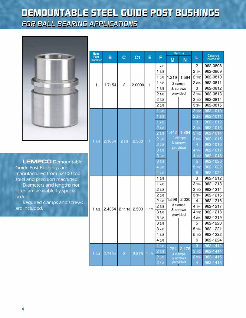
LEMPCO Demountable Guide Post Bushings are manufactured from 52100 tool steel and precision machined. Diameters and lengths not listed are available by special order. Required clamps and screws are included.
1 1.7154 2 2.0000 1
1 1/4 2.1054 2 3/8 2.360 1
1 1/2 2.4354 2 11/16 2.500 1 1/4
1 3/4 2.7454 3 2.875 1 1/4
Nom. Post
DiameterB C
7/8 2 962-0808 1 1/8 2 1/4 962-0809 1 3/8 2 1/2 962-0810 1 5/8 2 3/4 962-0811 1 7/8 3 962-0812 2 1/8 3 1/4 962-0813 2 3/8 3 1/2 962-0814 2 5/8 3 3/4 962-0815 1 3/8 2 1/2 962-1010 1 5/8 2 3/4 962-1011 1 7/8 3 962-1012 2 1/8 3 1/4 962-1013 2 3/8 3 1/2 962-1014 2 5/8 3 3/4 962-1015 2 7/8 4 962-1016 3 1/8 4 1/4 962-1017 3 3/8 4 1/2 962-1018 3 7/8 5 962-1020 4 3/8 5 1/2 962-1022 4 7/8 6 962-1024 1 5/8 3 962-1212 1 7/8 3 1/4 962-1213 2 1/8 3 1/2 962-1214 2 3/8 3 3/4 962-1215 2 5/8 4 962-1216 2 7/8 4 1/4 962-1217 3 1/8 4 1/2 962-1218 3 3/8 4 3/4 962-1219 3 5/8 5 962-1220 3 7/8 5 1/4 962-1221 4 1/8 5 1/2 962-1222 4 5/8 6 962-1224 1 5/8 3 962-1412 2 1/8 3 1/2 962-1414 2 3/8 3 3/4 962-1415 2 5/8 4 962-1416
3 clamps& screwsprovided
3 clamps& screwsprovided
3 clamps& screwsprovided
4 clamps& screwsprovided
1.754 2.176
1.219 1.594
1.442 1.864
1.598 2.020
E FRadius
M NCatalogNumberLC1
5
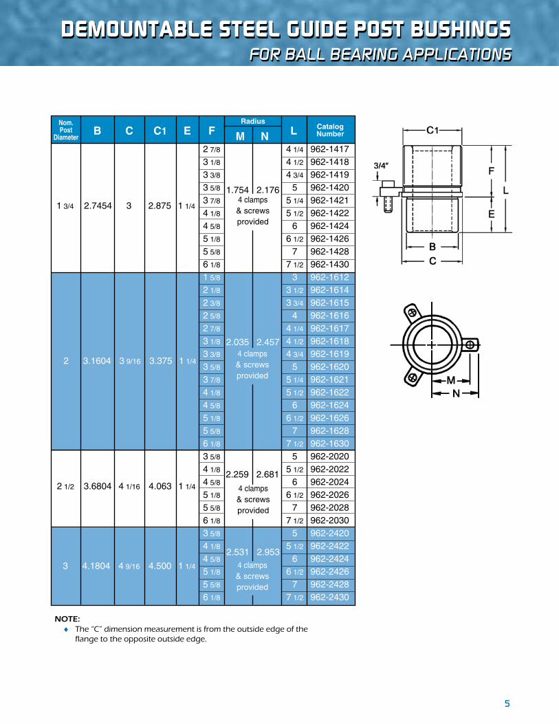
DemOUNTaBLe sTeeL GUIDe POsT BUshINGsFor Ball Bearing applications
NOTE: ♦ The “C” dimension measurement is from the outside edge of the flange to the opposite outside edge.
1 3/4 2.7454 3 2.875 1 1/4
2 3.1604 3 9/16 3.375 1 1/4
2 1/2 3.6804 4 1/16 4.063 1 1/4
3 4.1804 4 9/16 4.500 1 1/4
B CNom. Post
DiameterE
Radius
M NCatalogNumberL
2 7/8 4 1/4 962-1417 3 1/8 4 1/2 962-1418 3 3/8 4 3/4 962-1419 3 5/8 5 962-1420 3 7/8 5 1/4 962-1421 4 1/8 5 1/2 962-1422 4 5/8 6 962-1424 5 1/8 6 1/2 962-1426 5 5/8 7 962-1428 6 1/8 7 1/2 962-1430 1 5/8 3 962-1612 2 1/8 3 1/2 962-1614 2 3/8 3 3/4 962-1615 2 5/8 4 962-1616 2 7/8 4 1/4 962-1617 3 1/8 4 1/2 962-1618 3 3/8 4 3/4 962-1619 3 5/8 5 962-1620 3 7/8 5 1/4 962-1621 4 1/8 5 1/2 962-1622 4 5/8 6 962-1624 5 1/8 6 1/2 962-1626 5 5/8 7 962-1628 6 1/8 7 1/2 962-1630 3 5/8 5 962-2020 4 1/8 5 1/2 962-2022 4 5/8 6 962-2024 5 1/8 6 1/2 962-2026 5 5/8 7 962-2028 6 1/8 7 1/2 962-2030 3 5/8 5 962-2420 4 1/8 5 1/2 962-2422 4 5/8 6 962-2424 5 1/8 6 1/2 962-2426 5 5/8 7 962-2428 6 1/8 7 1/2 962-2430
4 clamps& screwsprovided
4 clamps& screwsprovided
4 clamps& screwsprovided
4 clamps& screwsprovided
2.531 2.953
2.259 2.681
F
1.754 2.176
2.035 2.457
C1

6
shOULDeR GUIDe POsT BUshINGsFor Ball Bearing applications
Shoulder Guide Post Bushings are manufactured from 52100 tool steel and precision ground. They are similar to LEMPCO Steel Demountable Bushings but are a minimum of .008” larger on the mounting diameter, corresponding to the additional material on the Shoulder Guide Post. They may be installed either by tap or press fitting. These bushings are interchangeable. See pages 13–15 for mounting instructions. Required clamps and screws are included.
Nom. Post
Diameter B C
1 1/2 2.445 2 11/16 2.500 1 1/4
1 1.725 2 2.000 1
1 1/4 2.115 2 3/8 2.360 1
E FRadius
M NCatalogNumberL
7/8 2 963-0808 1 1/8 2 1/4 963-0809 1 3/8 2 1/2 963-0810 1 5/8 2 3/4 963-0811 1 7/8 3 963-0812 2 1/8 3 1/4 963-0813 2 3/8 3 1/2 963-0814 2 5/8 3 3/4 963-0815 1 3/8 2 1/2 963-1010 1 5/8 2 3/4 963-1011 1 7/8 3 963-1012 2 1/8 3 1/4 963-1013 2 3/8 3 1/2 963-1014 2 5/8 3 3/4 963-1015 2 7/8 4 963-1016 3 1/8 4 1/4 963-1017 3 3/8 4 1/2 963-1018 3 7/8 5 963-1020 4 3/8 5 1/2 963-1022 4 7/8 6 963-1024 1 5/8 3 963-1212 1 7/8 3 1/4 963-1213 2 1/8 3 1/2 963-1214 2 3/8 3 3/4 963-1215 2 5/8 4 963-1216 2 7/8 4 1/4 963-1217 3 1/8 4 1/2 963-1218 3 3/8 4 3/4 963-1219 3 5/8 5 963-1220 3 7/8 5 1/4 963-1221 4 1/8 5 1/2 963-1222 4 5/8 6 963-1224
3 clamps& screwsprovided
3 clamps& screwsprovided
3 clamps& screwsprovided
1.219 1.594
1.442 1.864
1.598 2.020
C1

7
NOTE: ♦ The 963 Series product line is not stocked, but is available as a special order.
shOULDeR GUIDe POsT BUshINGsFor Ball Bearing applications
1 3/4 2.755 3 2.875 1 1/4
2 3.170 3 9/16 3.375 1 1/4
2 1/2 3.690 4 1/16 4.063 1 1/4
Nom. Post
Diameter B C EC1
1 5/8 3 963-1412 2 1/8 3 1/2 963-1414 2 3/8 3 3/4 963-1415 2 5/8 4 963-1416 2 7/8 4 1/4 963-1417 3 1/8 4 1/2 963-1418 3 3/8 4 3/4 963-1419 3 5/8 5 963-1420 3 7/8 5 1/4 963-1421 4 1/8 5 1/2 963-1422 4 5/8 6 963-1424 5 1/8 6 1/2 963-1426 5 5/8 7 963-1428 6 1/8 7 1/2 963-1430 1 5/8 3 963-1612 2 1/8 3 1/2 963-1614 2 3/8 3 3/4 963-1615 2 5/8 4 963-1616 2 7/8 4 1/4 963-1617 3 1/8 4 1/2 963-1618 3 3/8 4 3/4 963-1619 3 5/8 5 963-1620 3 7/8 5 1/4 963-1621 4 1/8 5 1/2 963-1622 4 5/8 6 963-1624 5 1/8 6 1/2 963-1626 5 5/8 7 963-1628 6 1/8 7 1/2 963-1630 3 5/8 5 963-2020 4 1/8 5 1/2 963-2022 4 5/8 6 963-2024 5 1/8 6 1/2 963-2026 5 5/8 7 963-2028 6 1/8 7 1/2 963-2030
FRadius
M NCatalogNumberL
4 clamps& screwsprovided
4 clamps& screwsprovided
4 clamps& screwsprovided
2.259 2.681
1.754 2.176
2.035 2.457
8
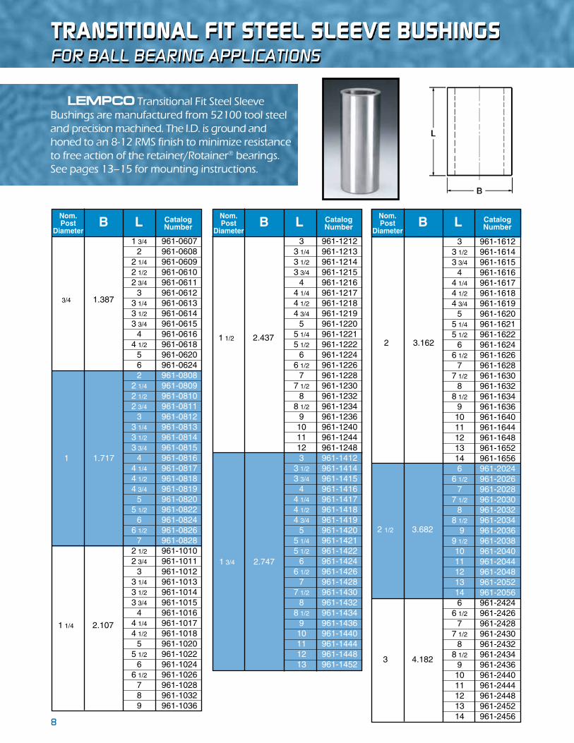
LEMPCO Transitional Fit Steel Sleeve Bushings are manufactured from 52100 tool steel and precision machined. The I.D. is ground and honed to an 8-12 RMS finish to minimize resistance to free action of the retainer/Rotainer® bearings. See pages 13–15 for mounting instructions.
Nom. Post
Diameter
CatalogNumberLB
2 3.162
2 1/2 3.682
3 4.182
3 961-1612 3 1/2 961-1614 3 3/4 961-1615 4 961-1616 4 1/4 961-1617 4 1/2 961-1618 4 3/4 961-1619 5 961-1620 5 1/4 961-1621 5 1/2 961-1622 6 961-1624 6 1/2 961-1626 7 961-1628 7 1/2 961-1630 8 961-1632 8 1/2 961-1634 9 961-1636 10 961-1640 11 961-1644 12 961-1648 13 961-1652 14 961-1656 6 961-2024 6 1/2 961-2026 7 961-2028 7 1/2 961-2030 8 961-2032 8 1/2 961-2034 9 961-2036 9 1/2 961-2038 10 961-2040 11 961-2044 12 961-2048 13 961-2052 14 961-2056 6 961-2424 6 1/2 961-2426 7 961-2428 7 1/2 961-2430 8 961-2432 8 1/2 961-2434 9 961-2436 10 961-2440 11 961-2444 12 961-2448 13 961-2452 14 961-2456
1 3/4 961-0607 2 961-0608 2 1/4 961-0609 2 1/2 961-0610 2 3/4 961-0611 3 961-0612 3 1/4 961-0613 3 1/2 961-0614 3 3/4 961-0615 4 961-0616 4 1/2 961-0618 5 961-0620 6 961-0624 2 961-0808 2 1/4 961-0809 2 1/2 961-0810 2 3/4 961-0811 3 961-0812 3 1/4 961-0813 3 1/2 961-0814 3 3/4 961-0815 4 961-0816 4 1/4 961-0817 4 1/2 961-0818 4 3/4 961-0819 5 961-0820 5 1/2 961-0822 6 961-0824 6 1/2 961-0826 7 961-0828 2 1/2 961-1010 2 3/4 961-1011 3 961-1012 3 1/4 961-1013 3 1/2 961-1014 3 3/4 961-1015 4 961-1016 4 1/4 961-1017 4 1/2 961-1018 5 961-1020 5 1/2 961-1022 6 961-1024 6 1/2 961-1026 7 961-1028 8 961-1032 9 961-1036
Nom. Post
Diameter
CatalogNumberLB
3/4 1.387
1 1.717
1 1/4 2.107
For Ball Bearing applications
3 961-1212 3 1/4 961-1213 3 1/2 961-1214 3 3/4 961-1215 4 961-1216 4 1/4 961-1217 4 1/2 961-1218 4 3/4 961-1219 5 961-1220 5 1/4 961-1221 5 1/2 961-1222 6 961-1224 6 1/2 961-1226 7 961-1228 7 1/2 961-1230 8 961-1232 8 1/2 961-1234 9 961-1236 10 961-1240 11 961-1244 12 961-1248 3 961-1412 3 1/2 961-1414 3 3/4 961-1415 4 961-1416 4 1/4 961-1417 4 1/2 961-1418 4 3/4 961-1419 5 961-1420 5 1/4 961-1421 5 1/2 961-1422 6 961-1424 6 1/2 961-1426 7 961-1428 7 1/2 961-1430 8 961-1432 8 1/2 961-1434 9 961-1436 10 961-1440 11 961-1444 12 961-1448 13 961-1452
Nom. Post
Diameter
CatalogNumberLB
1 1/2 2.437
1 3/4 2.747
TRaNsITIONaL FIT sTeeL sLeeve BUshINGs

9
3 951-0612 3 1/4 951-0613 3 1/2 951-0614 3 3/4 951-0615 4 951-0616 4 1/4 951-0617 4 1/2 951-0618 4 3/4 951-0619 5 951-0620 5 1/2 951-0622 6 951-0624 3 3/4 951-0815 4 951-0816 4 1/4 951-0817 4 1/2 951-0818 4 3/4 951-0819 5 951-0820 5 1/4 951-0821 5 1/2 951-0822 5 3/4 951-0823 6 951-0824 6 1/2 951-0826 7 951-0828 7 1/2 951-0830 8 951-0832 8 1/2 951-0834 9 951-0836 10 951-0840 11 951-0844 12 951-0848 4 1/2 951-1018 4 3/4 951-1019 5 951-1020 5 1/4 951-1021 5 1/2 951-1022 5 3/4 951-1023 6 951-1024 6 1/2 951-1026 7 951-1028 7 1/2 951-1030 8 951-1032 8 1/2 951-1034 9 951-1036 10 951-1040 11 951-1044 12 951-1048
PostDiameter Length Catalog
NumberA L
3/4
(.753)
1(1.003)
1 1/4
(1.253)
PostDiameter Length Catalog
NumberA L
1 1/2
(1.503)
1 3/4
(1.753)
4 1/2 951-1218 4 3/4 951-1219 5 951-1220 5 1/4 951-1221 5 1/2 951-1222 5 3/4 951-1223 6 951-1224 6 1/2 951-1226 7 951-1228 7 1/2 951-1230 8 951-1232 8 1/2 951-1234 9 951-1236 9 1/2 951-1238 10 951-1240 10 1/2 951-1242 11 951-1244 11 1/2 951-1246 12 951-1248 12 1/2 951-1250 13 951-1252 14 951-1256 5 951-1420 5 1/4 951-1421 5 1/2 951-1422 5 3/4 951-1423 6 951-1424 6 1/4 951-1425 6 1/2 951-1426 7 951-1428 7 1/2 951-1430 8 951-1432 8 1/2 951-1434 9 951-1436 9 1/2 951-1438 10 951-1440 10 1/2 951-1442 11 951-1444 11 1/2 951-1446 12 951-1448 12 1/2 951-1450 13 951-1452 14 951-1456 15 951-1460 17 951-1468
PostDiameter Length Catalog
NumberA L
2(2.003)
2 1/2
(2.503)
3(3.003)
5 1/2 951-1622 5 3/4 951-1623 6 951-1624 6 1/4 951-1625 6 1/2 951-1626 6 3/4 951-1627 7 951-1628 7 1/4 951-1629 7 1/2 951-1630 7 3/4 951-1631 8 951-1632 8 1/2 951-1634 9 951-1636 9 1/2 951-1638 10 951-1640 10 1/2 951-1642 11 951-1644 11 1/2 951-1646 12 951-1648 12 1/2 951-1650 13 951-1652 14 951-1656 15 951-1660 16 951-1664 17 951-1668 18 951-1672 8 951-2032 8 1/2 951-2034 9 951-2036 10 951-2040 11 951-2044 12 951-2048 13 951-2052 14 951-2056 17 951-2068 20 951-2080 8 951-2432 8 1/2 951-2434 9 951-2436 10 951-2440 11 951-2444 12 951-2448 13 951-2452 14 951-2456 17 951-2468 20 951-2480
sTRaIGhT GUIDe POsTsFor Ball Bearing applications
LEMPCO Straight Guide Posts for ball bearing assemblies are manufactured from 52100 tool steel and precision ground. See pages 13–15 for mounting instructions.
10
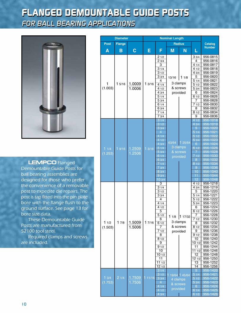
FLaNGeD DemOUNTaBLe GUIDe POsTsFor Ball Bearing applications
LEMPCO Flanged Demountable Guide Posts for ball bearing assemblies are designed for those who prefer the convenience of a removable post to expedite die repairs. The post is tap fitted into the pin plate bore with the flange flush to the ground surface. See page 13 for bore size data. These Demountable Guide Posts are manufactured from 52100 tool steel. Required clamps and screws are included.
2 1/2 3 3/4 956-0815 2 3/4 4 956-0816 3 4 1/4 956-0817 3 1/4 4 1/2 956-0818 3 1/2 4 3/4 956-0819 3 3/4 5 956-0820 4 5 1/4 956-0821 4 1/4 5 1/2 956-0822 4 1/2 5 3/4 956-0823 4 3/4 6 956-0824 5 1/4 6 1/2 956-0826 5 3/4 7 956-0828 6 1/4 7 1/2 956-0830 6 3/4 8 956-0832 7 1/4 8 1/2 956-0834 7 3/4 9 956-0836 3 1/4 4 1/2 956-1018 3 1/2 4 3/4 956-1019 3 3/4 5 956-1020 4 5 1/4 956-1021 4 1/4 5 1/2 956-1022 4 1/2 5 3/4 956-1023 4 3/4 6 956-1024 5 1/4 6 1/2 956-1026 5 3/4 7 956-1028 6 1/4 7 1/2 956-1030 6 3/4 8 956-1032 7 1/4 8 1/2 956-1034 7 3/4 9 956-1036 8 3/4 10 956-1040 9 3/4 11 956-1044 10 3/4 12 956-1048 3 4 1/2 956-1218 3 1/4 4 3/4 956-1219 3 1/2 5 956-1220 3 3/4 5 1/4 956-1221 4 5 1/2 956-1222 4 1/4 5 3/4 956-1223 4 1/2 6 956-1224 5 6 1/2 956-1226 5 1/2 7 956-1228 6 7 1/2 956-1230 6 1/2 8 956-1232 7 8 1/2 956-1234 7 1/2 9 956-1236 8 9 1/2 956-1238 8 1/2 10 956-1240 9 10 1/2 956-1242 9 1/2 11 956-1244 10 11 1/2 956-1246 10 1/2 12 956-1248 11 12 1/2 956-1250 11 1/2 13 956-1252 12 1/2 14 956-1256 3 1/4 5 956-1420 3 1/2 5 1/4 956-1421 3 3/4 5 1/2 956-1422 4 5 3/4 956-1423 4 1/4 6 956-1424 4 1/2 6 1/4 956-1425 4 3/4 6 1/2 956-1426
Diameter Nominal Length
CatalogNumber
RadiusPost Flange
A B C E F M N L
3 clamps& screwsprovided
4 clamps& screwsprovided
3 clamps& screwsprovided
3 clamps& screwsprovided
13/16 1 1/8
1 1 5/16 1.0009 1 3/16
1.0006(1.003)
63/64 1 25/64
1 1/4 1 9/16 1.2509 1 3/16
1.2506(1.253)
1 1/8 1 17/32
1 1/2 1 7/8 1.5009 1 7/16
1.5006(1.503)
1 19/64 1 45/64
(1.753) 1 3/4 2 1/4 1.7509 1 11/16
1.7506

11
FLaNGeD DemOUNTaBLe GUIDe POsTsFor Ball Bearing applications
5 1/4 7 956-1428 5 3/4 7 1/2 956-1430 6 1/4 8 956-1432 6 3/4 8 1/2 956-1434 7 1/4 9 956-1436 7 3/4 9 1/2 956-1438 8 1/4 10 956-1440 8 3/4 10 1/2 956-1442 9 1/4 11 956-1444 9 3/4 11 1/2 956-1446 10 1/4 12 956-1448 10 3/4 12 1/2 956-1450 11 1/4 13 956-1452 12 1/4 14 956-1456 13 1/4 15 956-1460 15 1/4 17 956-1468 3 1/2 5 1/2 956-1622 3 3/4 5 3/4 956-1623 4 6 956-1624 4 1/4 6 1/4 956-1625 4 1/2 6 1/2 956-1626 4 3/4 6 3/4 956-1627 5 7 956-1628 5 1/4 7 1/4 956-1629 5 1/2 7 1/2 956-1630 5 3/4 7 3/4 956-1631 6 8 956-1632 6 1/2 8 1/2 956-1634 7 9 956-1636 7 1/2 9 1/2 956-1638 8 10 956-1640 8 1/2 10 1/2 956-1642 9 11 956-1644 9 1/2 11 1/2 956-1646 10 12 956-1648 10 1/2 12 1/2 956-1650 11 13 956-1652 12 14 956-1656 13 15 956-1660 14 16 956-1664 15 17 956-1668 16 18 956-1672 6 8 956-2032 6 1/2 8 1/2 956-2034 7 9 956-2036 8 10 956-2040 9 11 956-2044 10 12 956-2048 11 13 956-2052 12 14 956-2056 15 17 956-2068 18 20 956-2080 5 1/2 8 956-2432 6 8 1/2 956-2434 6 1/2 9 956-2436 7 1/2 10 956-2440 8 1/2 11 956-2444 9 1/2 12 956-2448 10 1/2 13 956-2452 11 1/2 14 956-2456 14 1/2 17 956-2468 17 1/2 20 956-2480
Diameter Nominal Length
CatalogNumber
RadiusPost Flange
A B C E F M N L
(1.753) 1 3/4 2 1/4 1.7509 1 11/16
1.7506
4 clamps& screwsprovided
1 19/64 1 45/64
2 2 1/2 2.0009 1 15/16
2.0006(2.003)4 clamps& screwsprovided
1 27/64 1 53/64
(2.503) 2 1/2 3 2.5009 1 15/16
2.50064 clamps& screwsprovided
1 43/64 2 5/64
3 3 1/2 3.0009 2 7/16
3.0006(3.003)4 clamps& screwsprovided
1 59/64 2 21/64

12
shOULDeR GUIDe POsTsFor Ball Bearing applications
NOTE: ♦ The 953 Series product line is not stocked, but is available as a special order.
1 3/4 2.755 2 7/8 (1.753)
2 3.170 3 3/8 (2.003)
1 1/2 2.445 2 3/8 (1.503)
1 1/4 2.115 1 7/8 (1.253)
1 1.725 1 3/8 (1.003)
4 1/2 3 953-0818 5 3 1/2 953-0820 5 1/2 4 953-0822 6 4 1/2 953-0824 6 1/2 5 953-0826 7 5 1/2 953-0828 7 1/2 6 953-0830 8 6 1/2 953-0832 5 3 953-1020 5 1/2 3 1/2 953-1022 6 4 953-1024 6 1/2 4 1/2 953-1026 7 5 953-1028 7 1/2 5 1/2 953-1030 8 6 953-1032 8 1/2 6 1/2 953-1034 9 7 953-1036 7 4 5/8 953-1228 7 1/2 5 1/8 953-1230 8 5 5/8 953-1232 8 1/2 6 1/8 953-1234 9 6 5/8 953-1236 9 1/2 7 1/8 953-1238 10 7 5/8 953-1240 7 1/2 4 5/8 953-1430 8 5 1/8 953-1432 8 1/2 5 5/8 953-1434 9 6 1/8 953-1436 9 1/2 6 5/8 953-1438 10 7 1/8 953-1440 8 4 5/8 953-1632 9 5 5/8 953-1636 10 6 5/8 953-1640 11 7 5/8 953-1644 12 8 5/8 953-1648 13 9 5/8 953-1652 9 5 1/8 953-2036 10 6 1/8 953-2040 11 7 1/8 953-2044 12 8 1/8 953-2048 13 9 1/8 953-2052 14 10 1/8 953-2056
Diameter Length CatalogNumberA B L C D
2 1/2 3.690 3 7/8 (2.503)
Mounting diameters of the LEMPCO Shoulder Guide Posts are a minimum of .008” over the sizes of Press Fit Steel Sleeve Bushings and .008” over the Demountable Steel Bushings to allow grind stock for precision fitting in new set construction and to allow reboring as necessary in replacing posts and bushings in used sets. These posts also may be used with Press Fit Sleeve Bushings and Demountable Bushings providing the through bore size accords with mounting diameters. The Shoulder Guide Posts are manufactured from 52100 tool steel and precision ground. See pages 13–15 for mounting instructions.

13
BaLL BeaRING eNGINeeRING DaTa Boring procedures and dimensions
Holes for LEMPCO Ball Bearing Guide Posts and Bushings should be jig bored for best results. The punch holder and die holder should be clamped together and bored in one setup in order to maintain dead center alignment between the upper and lower bores. If it is not possible to bore in this manner, a tolerance of ±.0005” between centers (see illustration) must be held. Bores should be smooth and free from tool marks to provide proper bearing area for the guide post and bushing. Die holder bores must be perpendicular to the surface of the die holder which will back up the die. The bottom surface of the die holder must be parallel to the die backup surface. The punch holder bores also must be perpendicular to the surface which will back up the punches, and the top surface parallel to the punch back-up surface.
Break the corners of the bored holes to a generous chamfer. On sets with a symmetrical profile one pin and bushing should be offset to prevent accidental reversing of the punch holder during assembly. All of the LEMPCO Ball Bearing Guide Posts, Bushings Retainers and Rotainers® are completely interchangeable without the need for select fitting, and if mounted in accordance with boring and assembly instructions given on this and the following page do not require any grinding, honing, lapping, or any other modifications of any kind. Please note the dimensions given in the following table. Our experience over many years proves that these are optimum dimensions. Variations must be avoided.
BORE CHART – BALL BEARING COMPONENTS (INCH)
NominalGuidePost
Diameter
3/4 0.7515 / 0.7510 N/A N/A 1.3872 / 1.3867 N/A
1 1.0015 / 1.0010 1.0016 / 1.0009 1.7172 / 1.7167 1.7159 / 1.7154
1 1/4 1.2510 / 1.2505 1.2516 / 1.2509 2.1072 / 2.1067 2.1059 / 2.1054
1 1/2 1.5010 / 1.5005 1.5016 / 1.5009 2.4372 / 2.4367 2.4359 / 2.4354
1 3/4 1.7510 / 1.7505 1.7516 / 1.7509 2.7472 / 2.7467 2.7459 / 2.7454
2 2.0006 / 2.0001 2.0016 / 2.0009 3.1622 / 3.1617 3.1608 / 3.1603
2 1/2 2.5006 / 2.5001 2.5016 / 2.5009 3.6822 / 3.6817 3.6809 / 3.6804
3 3.0006 / 3.0001 3.0016 / 3.0009 N/A 4.1822 / 4.1817 4.1809 / 4.1804
BORE SIZE
#962-SERIESDEMOUNTABLE
SHOULDER BUSHING
(TAP FIT)
BORE SIZE
#961-SERIESSTRAIGHT
SLEEVE BUSHING
(TRANSITIONAL FIT)
#953-SERIESSHOULDERGUIDE PIN
(PRESS FIT)
BORE SIZE
#956-SERIESDEMOUNTABLE
GUIDE PIN
(TAP FIT)
BORE SIZE
#951-SERIESSTRAIGHTGUIDE PIN
(PRESS FIT)
BORE SIZE
BORE HOLE .0009” TO .0019” SMALLER THAN
SHOULDER DIAMETER OF GUIDE POST

14
In order to maintain the die and punch alignment, it is essential that the guide posts and bushings be at absolute right angles with the punch and die backup surfaces. Figure 1 represents a typical guide post and ROTAINER®. Please note that the end of the guide post with the small radius is press fit into the punch shoe, and that the ROTAINER® is assembled with the ROTAINER® slide assembly toward the same end of the guide post.
NOTE: LEMPCO Demountable Bushings and Flanged Demountable Guide Posts are tap fitted. Bores should be to specifications, and both bushings and guide posts should be seated flush to ground surface of support shoe and held securely by clamps and cap screws. These bushings and guide posts are removable; on installation the die will register accurately.
Check the squareness of the guide post or bushing with a precision square. Tap the sides slightly with a soft hammer until the guide post or bushing is perpendicular. Press fit about 1/4” (6.35mm) and check with the precision square again, tapping the sides with a soft hammer as necessary, to ensure squareness. A bronze, babbitt or fiber hammer is recom-mended.
NOTE: With Demountable Boss Bushings, be sure to press against the hardened liner and not against the casting.
Press fit by small increments – not over 1/2” (12.70mm) each – checking with the precision square after each press. Do not allow guide post or bushing to protrude through the lower side of the plate. It is advisable to place a 1/64” (.3968mm) shim under the guide post or bushing as a stop.
For Demountable Boss Bushings and Demountable Bushings, after the bushing is tap fit to the shoulder, the shoe may be drilled with the bushing in place. Tighten screws gradually, moving from one to another until all are tight. After complete assembly of the bushings, check the ID top and bottom for taper. Should taper be found, hone the ID until original size is obtained.
NOTE: This should not be necessary if boring instructions were strictly adhered to.
Assemble ROTAINER® to guide post (Figure 1) by screwing the set screw in until flush with the special ROTAINER® slide. Vertical and the rotational movement should now be tested to insure freedom of movement. After testing is completed, stake set screw. Lubricate only with a light spindle oil.
NOTE: The only tool necessary to assemble the ROTAINER® is a screw driver.
Assemble the punch and die holder. Be sure to allow the ROTAINERS® to hang free (see Figure 2) supported by the special ROTAINER® slide when assembling the die set. Work the punch holder up and down a few times to assure there is no binding.
BaLL BeaRING eNGINeeRING DaTa installation and assemBly instructions
FIGURE 2
Right Way Wrong Way Wrong Way
FIGURE 1
small radius
Guide Post
small radius
Guide Post
I.d. chamferI.d. chamfer
I.d. radius& chamferI.d. radius& chamfer
rotaIner®rotaIner®

15
SPECIFICATIONS:1. Maximum Shut Height – See Figure 2, below.
3. Stroke – See Figures 2 and 3.
2. Minimum Shut Height – See Figure 1.
4. Maximum Open Height – See Figures 2 and 3.
A. Lay out die as in Figure 1 (Minimum Shut Height). This determines maximum guide post length and maximum bushing height.
B. Lay out die as in Figure 2 (Maximum Shut Height).
C. Maximum Open Height (Maximum Shut Height plus Stroke) as in Figure 3 shows minimum guide post engagement in bushing that is required. If this is at least 3/4” then conditions are ideal. However, if this dimension is less than 3/4” then Figure 4 should be considered. Actual work is done for only a fraction of the total stroke on most dies and if conditions shown in Figure 4 are satisfied in conjunction with Figure 1 and Figure 2, then full length of stroke and maximum open height can be disregarded.
ALSO NOTE, HOWEVER, THAT LONGER THAN NORMAL STROKES MAY BE UTILIZED BY DISENGAGING GUIDE POST AND, IF ABSOLUTELY NECESSARY, THE ROTAINER® FROM THE BUSHING ON THE UPWARD TRAVEL PROVIDED: 1 – THE OPERATION IS VERTICAL 2 – THE OPERATION IS NOT FASTER THAN 150 STROKES PER MINUTE, AND 3 – THE INSIDE DIAMETER OF THE BUSHING IS BELL MOUTHED MINIMUM 1/4”.
ON INCLINED OPERATIONS, OR AT SPEEDS IN EXCESS OF 150 STROKES PER MINUTE, THE GUIDE POST MUST ENGAGE THE BUSHING AT ALL TIMES AT LEAST 3/4” (THE ROTAINER® MUST BE ENGAGED BY THE GUIDE POST AND BUSHINGS AT ALL TIMES).
BaLL BeaRING eNGINeeRING DaTa general die set design procedures
16
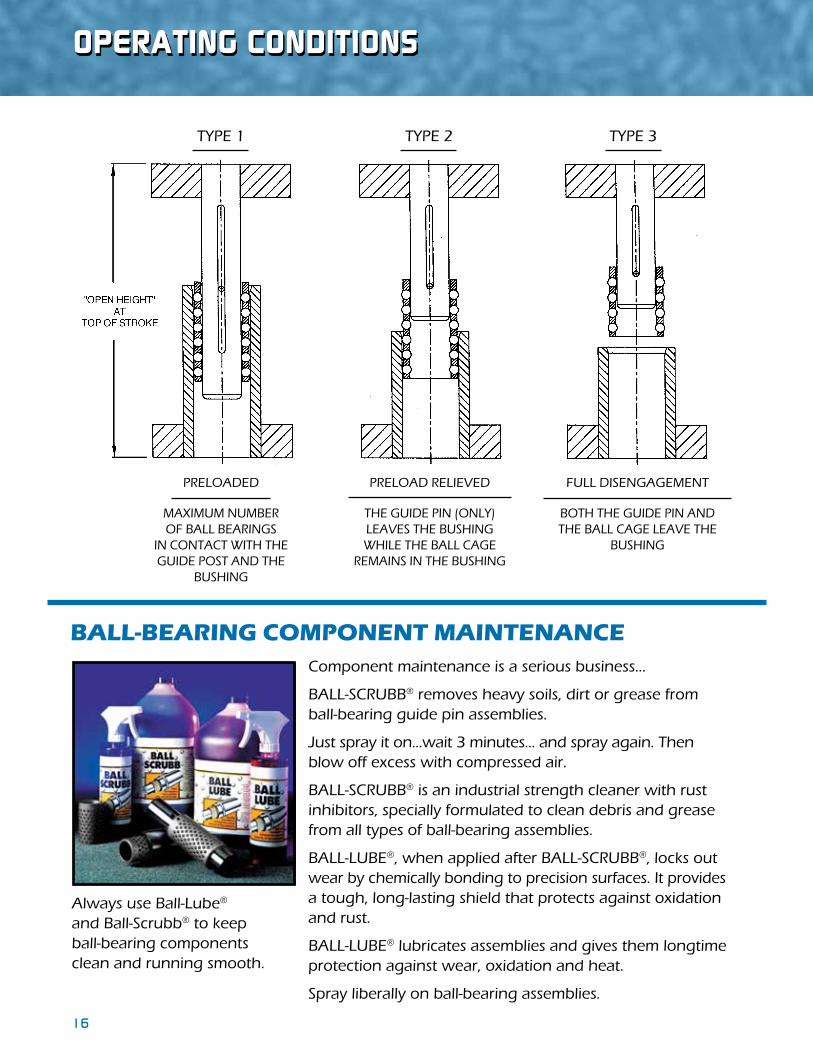
OPeRaTING CONDITIONs
TYPE 1 TYPE 2 TYPE 3
PRELOADED
MAXIMUM NUMBEROF BALL BEARINGS
IN CONTACT WITH THE GUIDE POST AND THE
BUSHING
PRELOAD RELIEVED
THE GUIDE PIN (ONLY) LEAVES THE BUSHING WHILE THE BALL CAGE
REMAINS IN THE BUSHING
FULL DISENGAGEMENT
BOTH THE GUIDE PIN AND THE BALL CAGE LEAVE THE
BUSHING
ball-bearInG comPonent maIntenanceComponent maintenance is a serious business...
BALL-SCRUBB® removes heavy soils, dirt or grease from ball-bearing guide pin assemblies.
Just spray it on...wait 3 minutes... and spray again. Then blow off excess with compressed air.
BALL-SCRUBB® is an industrial strength cleaner with rustinhibitors, specially formulated to clean debris and grease from all types of ball-bearing assemblies.
BALL-LUBE®, when applied after BALL-SCRUBB®, locks out wear by chemically bonding to precision surfaces. It provides a tough, long-lasting shield that protects against oxidation and rust.
BALL-LUBE® lubricates assemblies and gives them longtime protection against wear, oxidation and heat.
Spray liberally on ball-bearing assemblies.
Always use Ball-Lube® and Ball-Scrubb® to keep ball-bearing components clean and running smooth.

17
TeChNICaL BULLeTINFor Ball Bearing retainers
BACkGROUNd
Fatigue failures begin with a small crack in the material. The crack will develop at a point of discontinuity in the material, such as a change in cross section, a keyway, or a hole. Once a crack has developed, the stress-concentration effect becomes greater and the crack progresses more rapidly. As the stressed area decreases in size, the stress increases in magnitude until, finally, the remaining area fails suddenly.
The original LEMPCO ball staking design consisted of small rectangular indentations opposing each other at 180° degrees around the ball (two-point staking); see Figure 1. This staking design consists of no/minimal radii, two full corners, and numerous material discontinuities, all allowing opportunities for crack propagation.
SOLUTION
We developed an improved ball staking method that consists of a complete circular indentation around the entire ball (orbital staking); see Figure 2. This design utilizes a uniform circular metal forming technique, with no sharp discontinuities in the material. The new method is intended to improve performance in regards to operational life cycle.
CONCLUSION
After an independent third party* ran a Finite Element Analysis, the following can be concluded:
♦ The peak stress and stress levels in general are much higher for the two-point stake than for the orbital stake. Figure 3 shows stress contours for the two-point stake, Figure 4 shows stress contours for the orbital stake.
♦ Due to the smaller volume of material in the two-point stake, high stresses exist in a significant portion of the indented material.
♦ The differences in stress levels and distribution imply that the fatigue life for the two-point stake will be much less than for the orbital stake, and with the lower stresses the orbital stake should improve the fatigue life.
♦ The differences in stress levels of the orbital stake design also imply that press speed can be increased with the orbital stake compared to the two-point stake.
* O’Donnell Consulting Engineers, Inc. http://www.odonnellconsulting.com/fea.html
Figure 1:Two-Point Stake
Figure 2:Orbital Stake
Figure 3: Stake Stress – Two-Point
Figure 4: Stake Stress – Orbital

18
LemPCOLOY® PLaIN BeaRING BUshINGs
These unique hard coated aluminum bushings have the surface hardness of case hardened steel. An electrochemical process is used to increase the corrosion resistance of the bushings. As a result of this Hard Anodized process, they are also non-conductive, so they may be used for electrical discharge machining. They have a hard surface that is highly resistant to wear and not subject to magnetization. These bushings are for clean room and EDM applications and should not be used in any stamping operation wherein a lot of contaminants are generated. Lempcoloy® bushings do not require lubrication and therefore are not provided with the conventional figure-eight oil grooves and fittings. While these bushings do not require lubrication, we recommend you apply a light mist of spindle oil prior to assembly and spray lightly prior to each press run. Lempcoloy® bushings are designed to be installed by tap fitting to seat flush with the ground surface of the punch holder. They are assembled with toe clamps and screws. These bushings must not be pressed in or honed. These Lempcoloy® bushings will work well when used with Lamina plain bearing guide posts.

19
LemPCOLOY® PLaIN BeaRING BUshINGs
Clamps for Assembly
NOTE: ♦ For bushings with .002 over nominal ID to be used with a discontinued LEMPCO plain bearing guide post, remove the “–LAM” suffix from the part number.
Shoulder - Lempcoloy®
Short Shoulder - Lempcoloy®
Catalog Dia. A Radius
Number Nom. B C E F L M N
608-0409-LAM 1/2 0.812 15/16 5/8 1 1/2 2 1/8 0.697 1.010 608-0509-LAM 5/8 1.000 1 3/16 5/8 1 1/2 2 1/8 0.813 1.125 608-0611-LAM 3/4 1.125 1 5/16 7/8 1 3/4 2 5/8 0.875 1.188 608-0811-LAM 1 1.500 1 11/16 7/8 1 3/4 2 5/8 1.063 1.375 608-1013-LAM 1 1/4 1.750 1 15/16 1 1/8 2 3 1/8 1.219 1.531 608-1214-LAM 1 1/2 2.000 2 3/16 1 3/8 2 3 3/8 1.344 1.656 608-1414-LAM 1 3/4 2.250 2 1/2 1 3/8 2 3 3/8 1.500 1.813 608-1616-LAM 2 2.500 2 7/8 1 13/16 2 3 13/16 1.703 2.016 608-2018-LAM 2 1/2 3.250 3 5/8 1 13/16 2 1/2 4 5/16 2.078 2.391 608-2418-LAM 3 3.750 4 1/8 1 13/16 2 1/2 4 5/16 2.344 2.656
Inside
Catalog Dia. A Radius
Number Nom. B C E F L M N
607-0406-LAM 1/2 0.812 15/16 5/8 13/16 1 7/16 0.697 1.010 607-0506-LAM 5/8 1.000 1 3/16 5/8 13/16 1 7/16 0.813 1.125 607-0607-LAM 3/4 1.125 1 5/16 7/8 13/16 1 11/16 0.875 1.188 607-0807-LAM 1 1.500 1 11/16 7/8 13/16 1 11/16 1.063 1.375 607-1008-LAM 1 1/4 1.750 1 15/16 1 1/8 13/16 1 15/16 1.219 1.531 607-1209-LAM 1 1/2 2.000 2 3/16 1 3/8 13/16 2 3/16 1.344 1.656 607-1410-LAM 1 3/4 2.250 2 1/2 1 3/8 1 2 3/8 1.500 1.813 607-1612-LAM 2 2.500 2 7/8 1 13/16 1 2 13/16 1.703 2.016 607-2012-LAM 2 1/2 3.250 3 5/8 1 13/16 1 2 13/16 2.078 2.391 607-2412-LAM 3 3.750 4 1/8 1 13/16 1 2 13/16 2.344 2.656
Inside
Catalog Inside Number Number Dia. A of
Nom. Clamps
899-9025 1 2 899-9125 1 1/4 3 899-9125 1 1/2 3 899-9125 1 3/4 4 899-9125 2 4 899-9125 2 1/2 4 899-9125 3 4
20 21
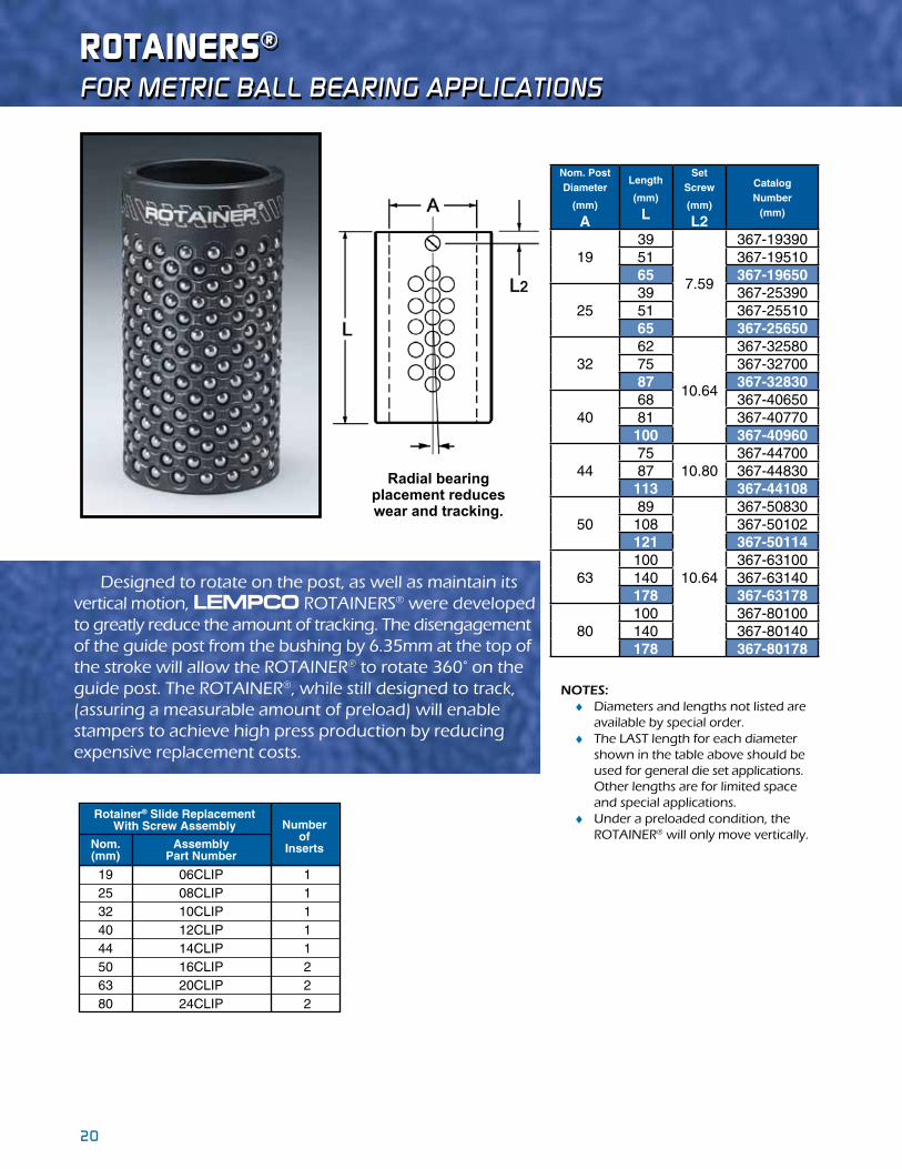
ROTaINeRs®
For metric Ball Bearing applications
Designed to rotate on the post, as well as maintain its vertical motion, LEMPCO ROTAINERS® were developed to greatly reduce the amount of tracking. The disengagement of the guide post from the bushing by 6.35mm at the top of the stroke will allow the ROTAINER® to rotate 360° on the guide post. The ROTAINER®, while still designed to track, (assuring a measurable amount of preload) will enable stampers to achieve high press production by reducing expensive replacement costs.
NOTES: ♦ Diameters and lengths not listed are available by special order. ♦ The LAST length for each diameter shown in the table above should be used for general die set applications. Other lengths are for limited space and special applications. ♦ Under a preloaded condition, the ROTAINER® will only move vertically.
Radial bearingplacement reduces wear and tracking.
Rotainer® Slide ReplacementWith Screw Assembly
Nom.(mm)
AssemblyPart Number
Numberof
Inserts
19 06CLIP 1 25 08CLIP 1 32 10CLIP 1 40 12CLIP 1 44 14CLIP 1 50 16CLIP 2 63 20CLIP 2 80 24CLIP 2
Nom. Post Diameter
(mm) A
Length
(mm) L
Set Screw
(mm) L2
Catalog Number
(mm)
1939
7.59
367-1939051 367-1951065 367-19650
2539 367-2539051 367-2551065 367-25650
3262
10.64
367-3258075 367-3270087 367-32830
4068 367-4065081 367-40770100 367-40960
4475
10.80367-44700
87 367-44830113 367-44108
5089
10.64
367-50830108 367-50102121 367-50114
63100 367-63100140 367-63140178 367-63178
80100 367-80100140 367-80140178 367-80178
20 21
For metric Ball Bearing applications
PReCIsION BaLL BeaRING ReTaINeRs
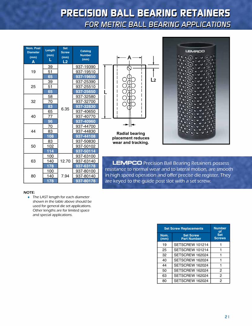
LEMPCO Precision Ball Bearing Retainers possess resistance to normal wear and to lateral motion, are smooth in high speed operation and offer precise die register. They are keyed to the guide post slot with a set screw.
NOTE: ♦ The LAST length for each diameter shown in the table above should be used for general die set applications. Other lengths are for limited space and special applications.
Radial bearingplacement reduces wear and tracking.
Set Screw Replacements
Nom.(mm)
Set ScrewPart Number
Numberof
SetScrews
19 SETSCREW 101214 1 25 SETSCREW 101214 1 32 SETSCREW 162024 1 40 SETSCREW 162024 1 44 SETSCREW 162024 1 50 SETSCREW 162024 2 63 SETSCREW 162024 2 80 SETSCREW 162024 2
Nom. Post Diameter
(mm) A
Length
(mm) L
Set Screw
(mm) L2
Catalog Number
(mm)
1939
6.35
937-1939051 937-1951065 937-19650
2539 937-2539051 937-2551065 937-25650
3258 937-3258070 937-3270083 937-32830
4065 937-4065077 937-4077096 937-40960
4470 937-4470083 937-44830108 937-44108
5083 937-50830102 937-50102114 937-50114
63100
12.70937-63100
140 937-63140178 937-63178
80100
7.94937-80100
140 937-80140178 937-80178

22 23
DemOUNTaBLe sTeeL GUIDe POsT BUshINGsFor metric Ball Bearing applications
LEMPCO Demountable Guide Post Bushings are manufactured from 52100 tool steel and precision machined. See pages 14 & 28 for mounting instructions. Diameters and lengths not listed are available by special order. Required clamps and screws are included.
25 55 966-25055 30 60 966-25060 35 65 966-25065 40 70 966-25070 45 75 966-25075 50 80 966-25080 55 85 966-25085 60 90 966-25090 65 95 966-25095 35 65 966-32065 40 70 966-32070 45 75 966-32075 50 80 966-32080 55 85 966-32085 60 90 966-32090 65 95 966-32095 75 105 966-32105 80 110 966-32110 85 115 966-32115 100 130 966-32130 110 140 966-32140 125 155 966-32155 40 75 966-40075 45 80 966-40080 50 85 966-40085 55 90 966-40090 60 95 966-40095 65 100 966-40100 75 110 966-40110 80 115 966-40115 85 120 966-40120 90 125 966-40125 100 135 966-40135 105 140 966-40140 120 155 966-40155
25 43.956 51 50.80 30 31 40.5
32 53.959 61 59.94 30 36.627 47.346
40 64.960 72 63.50 35 42.190 52.908
Radius
M NNom. Post
DiameterB C E F Catalog
NumberLC1

22 23
NOTES: ♦ The 966 Series product line is not stocked, but is available as a special order. ♦ The “C” dimension measurement is from the outside edge of the flange to the opposite outside edge.
DemOUNTaBLe sTeeL GUIDe POsT BUshINGsFor metric Ball Bearing applications
40 75 966-44075 55 90 966-44090 60 95 966-44095 65 100 966-44100 75 110 966-44110 80 115 966-44115 90 125 966-44125 100 135 966-44135 105 140 966-44140 120 155 966-44155 130 165 966-44165 145 180 966-44180 155 190 966-44190 40 75 966-50075 55 90 966-50090 60 95 966-50095 65 100 966-50100 75 110 966-50110 80 115 966-50115 90 125 966-50125 100 135 966-50135 105 140 966-50140 120 155 966-50155 130 165 966-50165 145 180 966-50180 155 190 966-50190 90 125 966-63125 105 140 966-63140 120 155 966-63155 130 165 966-63165 145 180 966-63180 155 190 966-63190 90 125 966-80125 105 140 966-80140 120 155 966-80155 130 165 966-80165 145 180 966-80180 155 190 966-80190
44 73.959 81 73.03 35 46.939 57.658
50 80.959 91 85.73 35 51.714 62.408
63 94.960 105 101.85 35 58.852 69.571
80 111.960 122 114.30 35 67.590 78.283
M N
Nom. Post
DiameterB C E F Catalog
NumberLRadius
C1
24 25
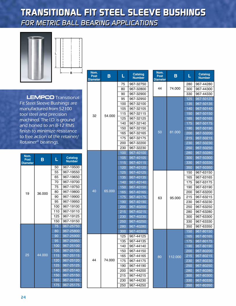
LEMPCO Transitional Fit Steel Sleeve Bushings are manufactured from 52100 tool steel and precision machined. The I.D. is ground and honed to an 8-12 RMS finish to minimize resistance to free action of the retainer/Rotainer® bearings.
75 967-32750 80 967-32800 90 967-32900 95 967-32950 100 967-32100 105 967-32105 115 967-32115 125 967-32125 140 967-32140 150 967-32150 165 967-32165 175 967-32175 200 967-32200 230 967-32230 100 967-40100 105 967-40105 115 967-40115 120 967-40120 125 967-40125 135 967-40135 140 967-40140 150 967-40150 165 967-40165 175 967-40175 190 967-40190 200 967-40200 215 967-40215 230 967-40230 250 967-40250 280 967-40280 300 967-40300 125 967-44125 135 967-44135 140 967-44140 150 967-44150 165 967-44165 175 967-44175 190 967-44190 200 967-44200 215 967-44215 230 967-44230 250 967-44250
Nom.Post
Diameter
CatalogNumberB L
40 65.000
32 54.000
44 74.000
50 967-19500 55 967-19550 65 967-19650 70 967-19700 75 967-19750 80 967-19800 90 967-19900 95 967-19950 100 967-19100 110 967-19110 125 967-19125 150 967-19150 75 967-25750 80 967-25800 90 967-25900 95 967-25950 100 967-25100 105 967-25105 115 967-25115 120 967-25120 125 967-25125 140 967-25140 150 967-25150 165 967-25165 175 967-25175
Nom.Post
Diameter
CatalogNumberB L
19 36.000
25 44.000
For metric Ball Bearing applications
280 967-44280 300 967-44300 330 967-44330 125 967-50125 135 967-50135 140 967-50140 150 967-50150 165 967-50165 175 967-50175 190 967-50190 200 967-50200 215 967-50215 230 967-50230 250 967-50250 280 967-50280 300 967-50300 330 967-50330 350 967-50350 150 967-63150 165 967-63165 175 967-63175 190 967-63190 200 967-63200 215 967-63215 230 967-63230 250 967-63250 280 967-63280 300 967-63300 330 967-63330 350 967-63350 150 967-80150 165 967-80165 175 967-80175 190 967-80190 200 967-80200 215 967-80215 230 967-80230 250 967-80250 280 967-80280 300 967-80300 330 967-80330 350 967-80350
44 74.000
50 81.000
Nom.Post
Diameter
CatalogNumberL
63 95.000
80 112.000
B
TRaNsITIONaL FIT sTeeL sLeeve BUshINGs

24 25
LEMPCO Straight Guide Posts for ball bearing assemblies are manufactured from 52100 tool steel and precision ground. See pages 14 & 28 for mounting instructions.
sTRaIGhT GUIDe POsTsFor metric Ball Bearing applications
250 957-50250 265 957-50265 280 957-50280 290 957-50290 300 957-50300 315 957-50315 330 957-50330 360 957-50360 380 957-50380 400 957-50400 430 957-50430 460 957-50460 200 957-63200 215 957-63215 230 957-63230 240 957-63240 250 957-63250 265 957-63265 280 957-63280 300 957-63300 315 957-63315 330 957-63330 360 957-63360 380 957-63380 430 957-63430 500 957-63500 200 957-80200 215 957-80215 230 957-80230 250 957-80250 280 957-80280 300 957-80300 330 957-80330 360 957-80360 430 957-80430 500 957-80500
PostDiameter Length Catalog
NumberA L
50
63
80
75 957-19750 90 957-19900 100 957-19100 110 957-19110 115 957-19115 120 957-19120 125 957-19125 150 957-19150 100 957-25100 110 957-25110 115 957-25115 120 957-25120 125 957-25125 135 957-25135 140 957-25140 145 957-25145 150 957-25150 165 957-25165 175 957-25175 190 957-25190 200 957-25200 215 957-25215 230 957-25230 125 957-32125 135 957-32135 140 957-32140 145 957-32145 150 957-32150 165 957-32165 175 957-32175 190 957-32190 200 957-32200 215 957-32215 230 957-32230 250 957-32250 260 957-32260 280 957-32280 300 957-32300 125 957-40125 135 957-40135 140 957-40140 145 957-40145 150 957-40150
PostDiameter Length Catalog
NumberA L
19
25
32
40
PostDiameter Length Catalog
NumberA L
40
44
50
165 957-40165 175 957-40175 190 957-40190 200 957-40200 215 957-40215 230 957-40230 240 957-40240 250 957-40250 265 957-40265 280 957-40280 290 957-40290 300 957-40300 315 957-40315 330 957-40330 360 957-40360 125 957-44125 135 957-44135 140 957-44140 145 957-44145 150 957-44150 165 957-44165 175 957-44175 190 957-44190 200 957-44200 215 957-44215 230 957-44230 240 957-44240 250 957-44250 265 957-44265 280 957-44280 290 957-44290 300 957-44300 315 957-44315 330 957-44330 360 957-44360 150 957-50150 165 957-50165 175 957-50175 190 957-50190 200 957-50200 215 957-50215 230 957-50230 240 957-50240

26 27
LEMPCO Flanged Demountable Guide Posts for ball bearing assemblies are designed for those who prefer the convenience of a removable post to expedite die repairs. The post is tap fitted into the pin plate bore with the flange flush to the ground surface. See pages 14 & 28 for mounting instructions. These Demountable Guide Posts are manufactured from 52100 tool steel. Required clamps and screws are included.
FLaNGeD DemOUNTaBLe GUIDe POsTsFor metric Ball Bearing applications
60 90 958-25090 70 100 958-25100 80 110 958-25110 85 115 958-25115 90 120 958-25120 95 125 958.25125 105 135 958-25135 110 140 958-25140 115 145 958-25145 120 150 958-25150 135 165 958-25165 145 175 958-25175 160 190 958-25190 170 200 958-25200 185 215 958-25215 200 230 958-25230 85 115 958-32115 90 120 958-32120 95 125 958-32125 105 135 958-32135 110 140 958-32140 115 145 958-32145 120 150 958-32150 135 165 958-32165 145 175 958-32175 160 190 958-32190 170 200 958-32200 185 215 958-32215 200 230 958-32230 220 250 958-32250 250 280 958-32280 270 300 958-32300 79 115 958-40115 84 120 958-40120 89 125 958-40125 99 135 958-40135 104 140 958-40140 109 145 958-40145 114 150 958-40150 129 165 958-40165 139 175 958-40175 154 190 958-40190 164 200 958-40200 179 215 958-40215 194 230 958-40230 204 240 958-40240 214 250 958-40250 224 260 958-40260 244 280 958-40280 254 290 958-40290 264 300 958-40300 279 315 958-40315 294 330 958-40330 324 360 958-40360 82 125 958-44125 92 135 958-44135 97 140 958-44140 102 145 958-44145 107 150 958-44150 112 155 958-44155 122 165 958-44165
Nominal Length
CatalogNumber
Flange
A B C E F L
43.952 57 43.952 43 43.939 43.939
39.952 48 39.952 36 39.939 39.939
24.953 33 24.953 30 24.940 24.940
31.953 40 31.953 30 31.940 31.940
Post
Diameter

26 27
Diameter Nominal Length
CatalogNumber
Post Flange
A B C E F L 132 175 958-44175 147 190 958-44190 157 200 958-44200 172 215 958-44215 187 230 958-44230 197 240 958-44240 207 250 958-44250 217 260 958-44260 237 280 958-44280 247 290 958-44290 257 300 958-44300 272 315 958-44315 287 330 958-44330 317 360 958-44360 337 380 958-44380 387 430 958-44430 91 140 958-50140 96 145 958-50145 101 150 958-50150 106 155 958-50155 116 165 958-50165 121 170 958-50170 126 175 958-50175 131 180 958-50180 141 190 958-50190 146 195 958-50195 151 200 958-50200 166 215 958-50215 181 230 958-50230 191 240 958-50240 201 250 958-50250 211 260 958-50260 231 280 958-50280 241 290 958-50290 251 300 958-50300 266 315 958-50315 281 330 958-50330 311 360 958-50360 331 380 958-50380 351 400 958-50400 381 430 958-50430 411 460 958-50460 151 200 958-63200 166 215 958-63215 181 230 958-63230 201 250 958-63250 231 280 958-63280 251 300 958-63300 281 330 958-63330 311 360 958-63360 381 430 958-63430 451 500 958-63500 138 200 958-80200 153 215 958-80215 168 230 958-80230 188 250 958-80250 218 280 958-80280 238 300 958-80300 268 330 958-80330 298 360 958-80360 368 430 958-80430 438 500 958-80500
49.952 63 49.952 49 49.939 49.939
43.952 57 43.952 43 43.939 43.939
62.952 76 62.952 49 62.939 62.939
79.952 93 79.952 62 79.939 79.939
19.05mm
FLaNGeD DemOUNTaBLe GUIDe POsTsFor metric Ball Bearing applications
28 2928 29
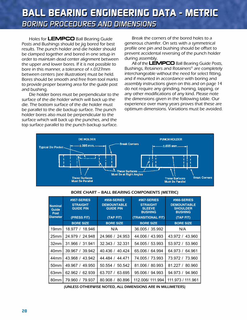
Holes for LEMPCO Ball Bearing Guide Posts and Bushings should be jig bored for best results. The punch holder and die holder should be clamped together and bored in one setup in order to maintain dead center alignment between the upper and lower bores. If it is not possible to bore in this manner, a tolerance of ±.0127mm between centers (see illustration) must be held. Bores should be smooth and free from tool marks to provide proper bearing area for the guide post and bushing. Die holder bores must be perpendicular to the surface of the die holder which will back up the die. The bottom surface of the die holder must be parallel to the die backup surface. The punch holder bores also must be perpendicular to the surface which will back up the punches, and the top surface parallel to the punch backup surface.
Break the corners of the bored holes to a generous chamfer. On sets with a symmetrical profile one pin and bushing should be offset to prevent accidental reversing of the punch holder during assembly. All of the LEMPCO Ball Bearing Guide Posts, Bushings, Retainers and Rotainers® are completely interchangeable without the need for select fitting, and if mounted in accordance with boring and assembly instructions given on this and on page 14 do not require any grinding, honing, lapping, or any other modifications of any kind. Please note the dimensions given in the following table. Our experience over many years proves that these are optimum dimensions. Variations must be avoided.
(UNLESS OTHERWISE NOTEd, ALL dIMENSIONS ARE IN MILLIMETERS)
BORE CHART – BALL BEARING COMPONENTS (METRIC)
BaLL BeaRING eNGINeeRING DaTa - meTRIC Boring procedures and dimensions
NominalGuidePost
Diameter
19mm 18.977 / 18.946 N/A 36.005 / 35.992 N/A
25mm 24.979 / 24.948 24.966 / 24.953 44.006 / 43.993 43.972 / 43.960
32mm 31.966 / 31.941 32.343 / 32.331 54.005 / 53.993 53.972 / 53.960
40mm 39.967 / 39.942 40.436 / 40.424 65.006 / 64.994 64.973 / 64.961
44mm 43.968 / 43.942 44.484 / 44.471 74.005 / 73.993 73.972 / 73.960
50mm 49.967 / 49.950 50.554 / 50.542 81.006 / 80.993 81.227 / 80.960
63mm 62.962 / 62.939 63.707 / 63.695 95.006 / 94.993 94.973 / 94.960
80mm 79.960 / 79.937 80.908 / 80.896 112.006 / 111.994 111.973 / 111.961
BORE SIZE
#966-SERIESDEMOUNTABLE
SHOULDERBUSHING
(TAP FIT)
BORE SIZE
#967-SERIESSTRAIGHT
SLEEVE BUSHING
(TRANSITIONAL FIT)
#958-SERIESDEMOUNTABLE
GUIDE PIN
(TAP FIT)
BORE SIZE
#957-SERIESSTRAIGHTGUIDE PIN
(PRESS FIT)
BORE SIZE

28 2928 29
incH and custom
DIe sPRINGs
MEdIUM dUTYColor Coded Blue Stripe
MEdIUM HEAVY dUTYColor Coded
Red Stripe
HEAVY dUTYColor Coded Gold Stripe
EXTRA HEAVY dUTYColor CodedGreen Stripe
dIe sPrInGs Product features ♦ Same day shipments – we stock them so you don’t have to
♦ Inch sizes manufactured to industry standard colors
♦ Reliable, trouble-free performance
♦ Manufactured in an ISO 9001:2008 certified facility
♦ Manufactured from spring-quality Chromium Silicon alloy, high-tensile
strength steel in accordance with ASTMA A1000-99 specifications
♦ Optimal rectangular wire design
A custom spring is any spring that has:
♦Unique physical attributes
Special wire material, plating or paint
Custom free lengths, diameters, solid heights,
rates, number of coils or custom loads at a
given deflection
♦Critical tolerances
♦Specific inspection or certification requirements
Military specifications
100% inspection of critical characteristics
♦Statistical reports
♦Computer controlled multi-point tests
custom sPrInGs

30 31
color coded Blue stripe
meDIUm DUTY DIe sPRINGs
* NOTE: For design purposes only. We do not recommend deflecting a spring to maximum deflection.
TotalDeflection TotalDeflection Maximum Pounds Recommended Recommended Operating *Max. Hole Rod Free Wire @1/10 forLongLife forAvg.Life Deflection Comp. Diam. Diam. Length Size CATALOG inch (25%ofC) (35%ofC) (40%ofC) Length (in) (in) (in) (in) NUMBER defl. Loadlbs. Defl.in. Loadlbs. Defl.in. Loadlbs. Defl.in. (in) 1.00 9-0604-1 6.2 15.5 0.25 21.7 0.35 24.8 0.40 0.48 3/8 3/16 1.25 9-0605-1 5.3 16.6 0.31 23.2 0.44 26.5 0.50 0.56 3/8 3/16 1.50 0.040 9-0606-1 4.2 15.6 0.38 21.8 0.53 24.9 0.60 0.68 3/8 3/16 1.75 X 9-0607-1 3.5 15.3 0.44 21.4 0.61 24.5 0.70 0.78 3/8 3/16 2.00 0.070 9-0608-1 2.9 14.5 0.50 20.3 0.70 23.2 0.80 0.94 3/8 3/16 2.50 9-0610-1 2.4 15.3 0.63 21.4 0.88 24.4 1.00 1.12 3/8 3/16 3.00 9-0612-1 2.1 15.8 0.75 22.1 1.05 25.2 1.20 1.40 12.00 9-0648-1 0.6 16.8 3.00 23.5 4.20 26.9 4.80 5.11 1.00 9-0804-1 10.7 26.8 0.25 37.5 0.35 42.8 0.40 0.45 1/2 9/32 1.25 9-0805-1 8.2 25.6 0.31 35.9 0.44 41.0 0.50 0.55 1/2 9/32 1.50 9-0806-1 6.8 25.5 0.38 35.7 0.53 40.8 0.60 0.66 1/2 9/32 1.75 9-0807-1 6.0 26.3 0.44 36.8 0.61 42.0 0.70 0.73 1/2 9/32 2.00 9-0808-1 5.3 26.5 0.50 37.1 0.70 42.4 0.80 0.82 1/2 9/32 2.50 0.052 9-0810-1 4.3 26.9 0.63 37.6 0.88 43.0 1.00 1.02 1/2 9/32 3.00 X 9-0812-1 3.4 25.5 0.75 35.7 1.05 40.8 1.20 1.25 1/2 9/32 3.50 0.095 9-0814-1 2.9 25.4 0.88 35.5 1.23 40.6 1.40 1.42 1/2 9/32 4.50 9-0818-1 2.4 27.0 1.13 37.8 1.58 43.2 1.80 1.82 1/2 9/32 5.50 9-0822-1 2.0 27.5 1.38 38.5 1.93 44.0 2.20 2.22 1/2 9/32 6.50 9-0826-1 1.4 22.8 1.63 31.9 2.28 36.4 2.60 2.65 1/2 9/32 7.50 9-0830-1 1.2 22.5 1.88 31.5 2.63 36.0 3.00 3.27 12.00 9-0848-1 0.7 21.0 3.00 29.4 4.20 33.6 4.80 5.24 1.00 9-1004-1 17.0 42.5 0.25 59.5 0.35 68.0 0.40 0.50 5/8 11/32 1.25 9-1005-1 13.0 40.6 0.31 56.9 0.44 65.0 0.50 0.62 5/8 11/32 1.50 9-1006-1 11.1 41.6 0.38 58.3 0.53 66.6 0.60 0.69 5/8 11/32 1.75 0.068 9-1007-1 9.6 42.0 0.44 58.8 0.61 67.2 0.70 0.80 5/8 11/32 2.00 X 9-1008-1 8.8 44.0 0.50 61.6 0.70 70.4 0.80 0.89 5/8 11/32 2.50 0.117 9-1010-1 6.3 39.4 0.63 55.1 0.88 63.0 1.00 1.16 5/8 11/32 3.00 9-1012-1 5.6 42.0 0.75 58.8 1.05 67.2 1.20 1.27 5/8 11/32 3.50 9-1014-1 4.8 42.0 0.88 58.8 1.23 67.2 1.40 1.46 5/8 11/32 4.00 9-1016-1 4.4 44.0 1.00 61.6 1.40 70.4 1.60 1.65 5/8 11/32 12.00 9-1048-1 1.5 45.6 3.00 63.8 4.20 73.0 4.80 4.83 1.00 9-1204-1 31.8 79.5 0.25 111.3 0.35 127.2 0.40 0.50 3/4 3/8 1.25 9-1205-1 25.6 80.0 0.31 112.0 0.44 128.0 0.50 0.65 3/4 3/8 1.50 9-1206-1 20.0 75.0 0.38 105.0 0.53 120.0 0.60 0.77 3/4 3/8 1.75 9-1207-1 17.6 77.0 0.44 107.8 0.61 123.2 0.70 0.88 3/4 3/8 2.00 9-1208-1 14.4 72.0 0.50 100.8 0.70 115.2 0.80 1.03 3/4 3/8 2.50 0.085 9-1210-1 12.0 75.0 0.63 105.0 0.88 120.0 1.00 1.28 3/4 3/8 3.00 X 9-1212-1 9.6 72.0 0.75 100.8 1.05 115.2 1.20 1.49 3/4 3/8 3.50 0.155 9-1214-1 8.0 70.0 0.88 98.0 1.23 112.0 1.40 1.74 3/4 3/8 4.00 9-1216-1 7.2 72.0 1.00 100.8 1.40 115.2 1.60 1.99 3/4 3/8 4.50 9-1218-1 6.4 72.0 1.13 100.8 1.58 115.2 1.80 2.24 3/4 3/8 5.00 9-1220-1 6.0 75.0 1.25 105.0 1.75 120.0 2.00 2.48 3/4 3/8 5.50 9-1222-1 5.5 75.6 1.38 105.9 1.93 121.0 2.20 2.72 3/4 3/8 6.00 9-1224-1 5.0 75.0 1.50 105.0 2.10 120.0 2.40 2.97 3/4 3/8 6.50 9-1226-1 4.5 73.1 1.63 102.4 2.28 117.0 2.60 3.20 3/4 3/8 7.50 9-1230-1 3.8 71.3 1.88 99.8 2.63 114.0 3.00 3.64 12.00 9-1248-1 2.4 72.0 3.00 100.8 4.20 115.2 4.80 5.84
1/2 9/32
3/4 3/8
5/8 11/32
3/8 3/160.040
X0.070
0.052X
0.095
0.068X
0.117
0.085X
0.155

30 31
color coded Blue stripe
INCh sTaNDaRD
TotalDeflection TotalDeflection Maximum Pounds Recommended Recommended Operating *Max. Hole Rod Free Wire @1/10 forLongLife forAvg.Life Deflection Comp. Diam. Diam. Length Size CATALOG inch (25%ofC) (35%ofC) (40%ofC) Length (in) (in) (in) (in) NUMBER defl. Loadlbs. Defl.in. Loadlbs. Defl.in. Loadlbs. Defl.in. (in)
1.00 9-1604-1 55.0 137.5 0.25 192.5 0.35 220.0 0.40 0.51 1 1/2 1.25 9-1605-1 45.0 140.6 0.31 196.9 0.44 225.0 0.50 0.66 1 1/2 1.50 9-1606-1 35.4 132.8 0.38 185.9 0.53 212.4 0.60 0.78 1 1/2 1.75 9-1607-1 30.0 131.3 0.44 183.8 0.61 210.0 0.70 0.90 1 1/2 2.00 9-1608-1 26.0 130.0 0.50 182.0 0.70 208.0 0.80 1.02 1 1/2 2.50 0.105 9-1610-1 20.2 126.3 0.63 176.8 0.88 202.0 1.00 1.27 1 1/2 3.00 X 9-1612-1 16.5 123.8 0.75 173.3 1.05 198.0 1.20 1.50 1 1/2 3.50 0.212 9-1614-1 15.0 131.3 0.88 183.8 1.23 210.0 1.40 1.75 1 1/2 4.00 9-1616-1 12.0 120.0 1.00 168.0 1.40 192.0 1.60 2.00 1 1/2 4.50 9-1618-1 10.5 118.1 1.13 165.4 1.58 189.0 1.80 2.25 1 1/2 5.00 9-1620-1 9.6 120.0 1.25 168.0 1.75 192.0 2.00 2.49 1 1/2 5.50 9-1622-1 8.8 121.0 1.38 169.4 1.93 193.6 2.20 2.74 1 1/2 6.00 9-1624-1 8.0 120.0 1.50 168.0 2.10 192.0 2.40 2.96 1 1/2 7.00 9-1628-1 7.2 126.0 1.75 176.4 2.45 201.6 2.80 3.48 1 1/2 8.00 9-1632-1 6.0 120.0 2.00 168.0 2.80 192.0 3.20 3.86 12.00 9-1648-1 4.0 120.0 3.00 168.0 4.20 192.0 4.80 5.76 1.50 9-2006-1 51.0 191.3 0.38 267.8 0.53 306.0 0.60 0.75 1 1/4 5/8 1.75 9-2007-1 42.4 185.5 0.44 259.7 0.61 296.8 0.70 0.88 1 1/4 5/8 2.00 9-2008-1 36.0 180.0 0.50 252.0 0.70 288.0 0.80 1.05 1 1/4 5/8 2.50 9-2010-1 28.8 180.0 0.63 252.0 0.88 288.0 1.00 1.25 1 1/4 5/8 3.00 9-2012-1 24.0 180.0 0.75 252.0 1.05 288.0 1.20 1.46 1 1/4 5/8 3.50 0.125 9-2014-1 20.0 175.0 0.88 245.0 1.23 280.0 1.40 1.70 1 1/4 5/8 4.00 X 9-2016-1 17.6 176.0 1.00 246.4 1.40 281.6 1.60 1.95 1 1/4 5/8 4.50 0.270 9-2018-1 16.0 180.0 1.13 252.0 1.58 288.0 1.80 2.20 1 1/4 5/8 5.00 9-2020-1 13.6 170.0 1.25 238.0 1.75 272.0 2.00 2.44 1 1/4 5/8 5.50 9-2022-1 12.8 176.0 1.38 246.4 1.93 281.6 2.20 2.72 1 1/4 5/8 6.00 9-2024-1 12.0 180.0 1.50 252.0 2.10 288.0 2.40 2.98 1 1/4 5/8 7.00 9-2028-1 10.4 182.0 1.75 254.8 2.45 291.2 2.80 3.50 1 1/4 5/8 8.00 9-2032-1 8.8 176.0 2.00 246.4 2.80 281.6 3.20 3.98 1 1/4 5/8 10.00 9-2040-1 7.2 180.0 2.50 252.0 3.50 288.0 4.00 4.98 12.00 9-2048-1 6.0 180.0 3.00 252.0 4.20 288.0 4.80 5.98 2.00 9-2408-1 54.7 273.5 0.50 382.9 0.70 437.6 0.80 1.03 1 1/2 3/4 2.50 9-2410-1 44.7 279.4 0.63 391.1 0.88 447.0 1.00 1.27 1 1/2 3/4 3.00 9-2412-1 36.0 270.0 0.75 378.0 1.05 432.0 1.20 1.52 1 1/2 3/4 3.50 9-2414-1 30.0 262.5 0.88 367.5 1.23 420.0 1.40 1.74 1 1/2 3/4 4.00 0.158 9-2416-1 27.0 270.0 1.00 378.0 1.40 432.0 1.60 1.99 1 1/2 3/4 4.50 X 9-2418-1 23.0 258.8 1.13 362.3 1.58 414.0 1.80 2.22 1 1/2 3/4 5.00 0.315 9-2420-1 21.0 262.5 1.25 367.5 1.75 420.0 2.00 2.46 1 1/2 3/4 5.50 9-2422-1 18.5 254.4 1.38 356.1 1.93 407.0 2.20 2.72 1 1/2 3/4 6.00 9-2424-1 17.0 255.0 1.50 357.0 2.10 408.0 2.40 2.96 1 1/2 3/4 7.00 9-2428-1 14.5 253.8 1.75 355.3 2.45 406.0 2.80 3.401 1/2 3/4 8.00 9-2432-1 12.8 256.0 2.00 358.4 2.80 409.6 3.20 3.901 1/2 3/4 10.00 9-2440-1 10.0 250.0 2.50 350.0 3.50 400.0 4.00 4.86 12.00 9-2448-1 8.2 246.0 3.00 344.4 4.20 393.6 4.80 5.86 2.50 9-3210-1 100.0 625.0 0.63 875.0 0.88 1000.0 1.00 1.37 2 1 3.00 9-3212-1 83.0 622.5 0.75 871.5 1.05 996.0 1.20 1.58 2 1 3.50 9-3214-1 65.8 575.8 0.88 806.1 1.23 921.2 1.40 1.84 2 1 4.00 9-3216-1 60.0 600.0 1.00 840.0 1.40 960.0 1.60 2.08 2 1 4.50 0.215 9-3218-1 53.0 596.3 1.13 834.8 1.58 954.0 1.80 2.20 2 1 5.00 X 9-3220-1 47.0 587.5 1.25 822.5 1.75 940.0 2.00 2.58 2 1 5.50 0.445 9-3222-1 39.8 547.3 1.38 766.2 1.93 875.6 2.20 2.88 2 1 6.00 9-3224-1 39.0 585.0 1.50 819.0 2.10 936.0 2.40 3.03 2 1 7.00 9-3228-1 31.6 553.0 1.75 774.2 2.45 884.8 2.80 3.58 2 1 8.00 9-3232-1 28.5 570.0 2.00 798.0 2.80 912.0 3.20 4.05 2 1 10.00 9-3240-1 20.8 520.0 2.50 728.0 3.50 832.0 4.00 5.00 12.00 9-3248-1 17.5 525.0 3.00 735.0 4.20 840.0 4.80 6.17
1 1/2
1-1/4 5/8
1-1/2 3/4
2 1
0.105X
0.212
0.125X
0.270
0.158X
0.315
0.215X
0.445
* NOTE: For design purposes only. We do not recommend deflecting a spring to maximum deflection.

32 33
* NOTE: For design purposes only. We do not recommend deflecting a spring to maximum deflection.
color coded red stripe
meDIUm heavY DUTY DIe sPRINGs
TotalDeflection TotalDeflection Maximum Pounds Recommended Recommended Operating *Max. Hole Rod Free Wire @1/10 forLongLife forAvg.Life Deflection Comp. Diam. Diam. Length Size CATALOG inch (20%ofC) (25%ofC) (35%ofC) Length (in) (in) (in) (in) NUMBER defl. Loadlbs. Defl.in. Loadlbs. Defl.in. Loadlbs. Defl.in. (in)
1.00 9-0604-2 9.0 18.0 0.20 22.5 0.25 31.5 0.35 0.58 3/8 3/16 1.25 9-0605-2 7.3 18.3 0.25 22.8 0.31 31.9 0.44 0.71 3/8 3/16 1.50 0.045 9-0606-2 6.7 20.1 0.30 25.1 0.38 35.2 0.53 0.85 3/8 3/16 1.75 X 9-0607-2 5.7 20.0 0.35 24.9 0.44 34.9 0.61 0.95 3/8 3/16 2.00 0.070 9-0608-2 5.0 20.0 0.40 25.0 0.50 35.0 0.70 1.09 3/8 3/16 2.50 9-0610-2 4.0 20.0 0.50 25.0 0.63 35.0 0.88 1.36 3/8 3/16 3.00 9-0612-2 3.0 18.0 0.60 22.5 0.75 31.5 1.05 1.69 12.00 9-0648-2 0.8 19.2 2.40 24.0 3.00 33.6 4.20 6.46 1.00 9-0804-2 16.6 33.2 0.20 41.5 0.25 58.1 0.35 0.50 1/2 9/32 1.25 9-0805-2 13.0 32.5 0.25 40.6 0.31 56.9 0.44 0.61 1/2 9/32 1.50 9-0806-2 9.9 29.7 0.30 37.1 0.38 52.0 0.53 0.72 1/2 9/32 1.75 0.060 9-0807-2 8.5 29.8 0.35 37.2 0.44 52.1 0.61 0.84 1/2 9/32 2.00 X 9-0808-2 7.5 30.0 0.40 37.5 0.50 52.5 0.70 0.95 1/2 9/32 2.50 0.095 9-0810-2 6.0 30.0 0.50 37.5 0.63 52.5 0.88 1.18 1/2 9/32 3.00 9-0812-2 5.5 33.0 0.60 41.3 0.75 57.8 1.05 1.40 1/2 9/32 3.50 9-0814-2 4.0 28.0 0.70 35.0 0.88 49.0 1.23 1.68 12.00 9-0848-2 1.2 28.8 2.40 36.0 3.00 50.4 4.20 5.68 1.00 9-1004-2 30.0 60.0 0.20 75.0 0.25 105.0 0.35 0.56 5/8 11/32 1.25 9-1005-2 21.5 53.8 0.25 67.2 0.31 94.1 0.44 0.70 5/8 11/32 1.50 9-1006-2 19.2 57.6 0.30 72.0 0.38 100.8 0.53 0.79 5/8 11/32 1.75 0.086 9-1007-2 16.8 58.8 0.35 73.5 0.44 102.9 0.61 0.92 5/8 11/32 2.00 X 9-1008-2 14.8 59.2 0.40 74.0 0.50 103.6 0.70 1.00 5/8 11/32 2.50 0.112 9-1010-2 11.5 57.5 0.50 71.9 0.63 100.6 0.88 1.22 5/8 11/32 3.00 9-1012-2 10.0 60.0 0.60 75.0 0.75 105.0 1.05 1.43 5/8 11/32 3.50 9-1014-2 8.5 59.5 0.70 74.4 0.88 104.1 1.23 1.69 5/8 11/32 4.00 9-1016-2 7.6 60.8 0.80 76.0 1.00 106.4 1.40 1.92 12.00 9-1048-2 2.6 62.4 2.40 78.0 3.00 109.2 4.20 5.70 1.00 9-1204-2 50.0 100.0 0.20 125.0 0.25 175.0 0.35 0.58 3/4 3/8 1.25 9-1205-2 38.0 95.0 0.25 118.8 0.31 166.3 0.44 0.72 3/4 3/8 1.50 9-1206-2 32.0 96.0 0.30 120.0 0.38 168.0 0.53 0.87 3/4 3/8 1.75 9-1207-2 28.5 99.8 0.35 124.7 0.44 174.6 0.61 1.02 3/4 3/8 2.00 9-1208-2 24.8 99.2 0.40 124.0 0.50 173.6 0.70 1.16 3/4 3/8 2.50 0.100 9-1210-2 19.2 96.0 0.50 120.0 0.63 168.0 0.88 1.46 3/4 3/8 3.00 X 9-1212-2 14.4 86.4 0.60 108.0 0.75 151.2 1.05 1.74 3/4 3/8 3.50 0.155 9-1214-2 12.8 89.6 0.70 112.0 0.88 156.8 1.23 2.02 3/4 3/8 4.00 9-1216-2 12.0 96.0 0.80 120.0 1.00 168.0 1.40 2.31 3/4 3/8 4.50 9-1218-2 11.0 99.0 0.90 123.8 1.13 173.3 1.58 2.62 3/4 3/8 5.00 9-1220-2 9.0 90.0 1.00 112.5 1.25 157.5 1.75 2.86 3/4 3/8 5.50 9-1222-2 8.0 88.0 1.10 110.0 1.38 154.0 1.93 3.15 3/4 3/8 6.00 9-1224-2 7.5 90.0 1.20 112.5 1.50 157.5 2.10 3.45 12.00 9-1248-2 3.6 86.4 2.40 108.0 3.00 151.2 4.20 6.78
3/8 3/16
5/8 11/32
1/2 9/32
3/4 3/8
0.045X
0.070
0.060X
0.095
0.086X
0.112
0.100X
0.155

32 33
* NOTE: For design purposes only. We do not recommend deflecting a spring to maximum deflection.
color coded red stripe
INCh sTaNDaRD
TotalDeflection TotalDeflection Maximum Pounds Recommended Recommended Operating *Max. Hole Rod Free Wire @1/10 forLongLife forAvg.Life Deflection Comp. Diam. Diam. Length Size CATALOG inch (20%ofC) (25%ofC) (35%ofC) Length (in) (in) (in) (in) NUMBER defl. Loadlbs. Defl.in. Loadlbs. Defl.in. Loadlbs. Defl.in. (in)
1.00 9-1604-2 76.0 152.0 0.20 190.0 0.25 266.0 0.35 0.61 1 1/2 1.25 9-1605-2 62.4 156.0 0.25 195.0 0.31 273.0 0.44 0.75 1 1/2 1.50 9-1606-2 49.6 148.8 0.30 186.0 0.38 260.4 0.53 0.89 1 1/2 1.75 9-1607-2 44.0 154.0 0.35 192.5 0.44 269.5 0.61 1.02 1 1/2 2.00 9-1608-2 40.0 160.0 0.40 200.0 0.50 280.0 0.70 1.15 1 1/2 2.50 0.125 9-1610-2 31.0 155.0 0.50 193.8 0.63 271.3 0.88 1.44 1 1/2 3.00 X 9-1612-2 25.0 150.0 0.60 187.5 0.75 262.5 1.05 1.73 1 1/2 3.50 0.214 9-1614-2 21.6 151.2 0.70 189.0 0.88 264.6 1.23 2.02 1 1/2 4.00 9-1616-2 18.4 147.2 0.80 184.0 1.00 257.6 1.40 2.30 1 1/2 4.50 9-1618-2 17.0 153.0 0.90 191.3 1.13 267.8 1.58 2.59 1 1/2 5.00 9-1620-2 14.4 144.0 1.00 180.0 1.25 252.0 1.75 2.88 1 1/2 5.50 9-1622-2 12.8 140.8 1.10 176.0 1.38 246.4 1.93 3.16 1 1/2 6.00 9-1624-2 12.0 144.0 1.20 180.0 1.50 252.0 2.10 3.45 1 1/2 7.00 9-1628-2 10.0 140.0 1.40 175.0 1.75 245.0 2.45 4.03 1 1/2 8.00 9-1632-2 8.8 140.8 1.60 176.0 2.00 246.4 2.80 4.60 12.00 9-1648-2 6.2 148.8 2.40 186.0 3.00 260.4 4.20 6.70 1.50 9-2006-2 113.4 340.2 0.30 425.3 0.38 595.4 0.53 0.921 1/4 5/8 1.75 9-2007-2 94.5 330.8 0.35 413.4 0.44 578.8 0.61 1.071 1/4 5/8 2.00 9-2008-2 81.0 324.0 0.40 405.0 0.50 567.0 0.70 1.221 1/4 5/8 2.50 9-2010-2 62.4 312.0 0.50 390.0 0.63 546.0 0.88 1.551 1/4 5/8 3.00 9-2012-2 51.2 307.2 0.60 384.0 0.75 537.6 1.05 1.831 1/4 5/8 3.50 0.165 9-2014-2 43.5 304.5 0.70 380.6 0.88 532.9 1.23 2.121 1/4 5/8 4.00 X 9-2016-2 36.8 294.4 0.80 368.0 1.00 515.2 1.40 2.431 1/4 5/8 4.50 0.270 9-2018-2 32.0 288.0 0.90 360.0 1.13 504.0 1.58 2.681 1/4 5/8 5.00 9-2020-2 29.0 290.0 1.00 362.5 1.25 507.5 1.75 2.941 1/4 5/8 5.50 9-2022-2 26.4 290.4 1.10 363.0 1.38 508.2 1.93 3.221 1/4 5/8 6.00 9-2024-2 25.0 300.0 1.20 375.0 1.50 525.0 2.10 3.581 1/4 5/8 7.00 9-2028-2 20.0 280.0 1.40 350.0 1.75 490.0 2.45 4.101 1/4 5/8 8.00 9-2032-2 18.4 294.4 1.60 368.0 2.00 515.2 2.80 4.76 8 1/4 5/8 10.00 9-2040-2 14.5 290.0 2.00 362.5 2.50 507.5 3.50 5.78 12.00 9-2048-2 12.1 290.4 2.40 363.0 3.00 508.2 4.20 6.94 2.00 9-2408-2 104.0 416.0 0.40 520.0 0.50 728.0 0.70 1.211 1/2 3/4 2.50 9-2410-2 81.5 407.5 0.50 509.4 0.63 713.1 0.88 1.511 1/2 3/4 3.00 9-2412-2 62.4 374.4 0.60 468.0 0.75 655.2 1.05 1.751 1/2 3/4 3.50 9-2414-2 52.8 369.6 0.70 462.0 0.88 646.8 1.23 2.081 1/2 3/4 4.00 9-2416-2 47.3 378.4 0.80 473.0 1.00 662.2 1.40 2.311 1/2 3/4 4.50 0.191 9-2418-2 41.6 374.4 0.90 468.0 1.13 655.2 1.58 2.581 1/2 3/4 5.00 X 9-2420-2 36.8 368.0 1.00 460.0 1.25 644.0 1.75 2.821 1/2 3/4 5.50 0.320 9-2422-2 33.6 369.6 1.10 462.0 1.38 646.8 1.93 3.051 1/2 3/4 6.00 9-2424-2 30.4 364.8 1.20 456.0 1.50 638.4 2.10 3.451 1/2 3/4 7.00 9-2428-2 26.4 369.6 1.40 462.0 1.75 646.8 2.45 3.891 1/2 3/4 8.00 9-2432-2 22.0 352.0 1.60 440.0 2.00 616.0 2.80 4.451 1/2 3/4 10.00 9-2440-2 17.6 352.0 2.00 440.0 2.50 616.0 3.50 5.55 12.00 9-2448-2 14.4 345.6 2.40 432.0 3.00 604.8 4.20 6.80 2.50 9-3210-2 118.4 592.0 0.50 740.0 0.63 1036.0 0.88 1.47 2 1 3.00 9-3212-2 96.0 576.0 0.60 720.0 0.75 1008.0 1.05 1.77 2 1 3.50 9-3214-2 80.0 560.0 0.70 700.0 0.88 980.0 1.23 2.05 2 1 4.00 9-3216-2 66.4 531.2 0.80 664.0 1.00 929.6 1.40 2.32 2 1 4.50 0.235 9-3218-2 60.0 540.0 0.90 675.0 1.13 945.0 1.58 2.60 2 1 5.00 X 9-3220-2 55.1 551.0 1.00 688.8 1.25 964.3 1.75 2.92 2 1 5.50 0.440 9-3222-2 49.7 546.7 1.10 683.4 1.38 956.7 1.93 3.18 2 1 6.00 9-3224-2 45.3 543.6 1.20 679.5 1.50 951.3 2.10 3.46 2 1 7.00 9-3228-2 38.5 539.0 1.40 673.8 1.75 943.3 2.45 4.05 2 1 8.00 9-3232-2 33.5 536.0 1.60 670.0 2.00 938.0 2.80 4.62 2 1 10.00 9-3240-2 26.0 520.0 2.00 650.0 2.50 910.0 3.50 5.75 12.00 9-3248-2 21.9 525.6 2.40 657.0 3.00 919.8 4.20 6.88
1 1/2
1-1/2 3/4
1-1/4 5/8
2 1
0.125X
0.214
0.165X
0.270
0.191X
0.320
0.235X
0.440
34 35
* NOTE: For design purposes only. We do not recommend deflecting a spring to maximum deflection.
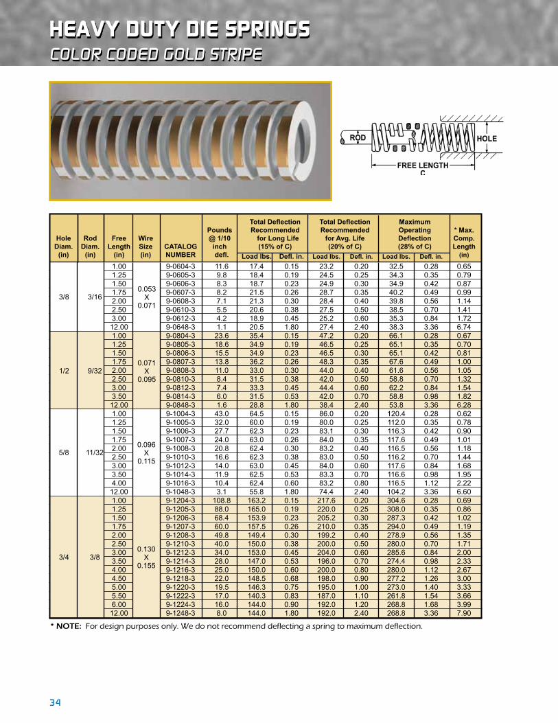
heavY DUTY DIe sPRINGscolor coded gold stripe
TotalDeflection TotalDeflection Maximum Pounds Recommended Recommended Operating *Max. Hole Rod Free Wire @1/10 forLongLife forAvg.Life Deflection Comp. Diam. Diam. Length Size CATALOG inch (15%ofC) (20%ofC) (28%ofC) Length (in) (in) (in) (in) NUMBER defl. Loadlbs. Defl.in. Loadlbs. Defl.in. Loadlbs. Defl.in. (in)
1.00 9-0604-3 11.6 17.4 0.15 23.2 0.20 32.5 0.28 0.65 3/8 3/16 1.25 9-0605-3 9.8 18.4 0.19 24.5 0.25 34.3 0.35 0.79 3/8 3/16 1.50 0.053 9-0606-3 8.3 18.7 0.23 24.9 0.30 34.9 0.42 0.87 3/8 3/16 1.75 X 9-0607-3 8.2 21.5 0.26 28.7 0.35 40.2 0.49 0.99 3/8 3/16 2.00 0.071 9-0608-3 7.1 21.3 0.30 28.4 0.40 39.8 0.56 1.14 3/8 3/16 2.50 9-0610-3 5.5 20.6 0.38 27.5 0.50 38.5 0.70 1.41 3/8 3/16 3.00 9-0612-3 4.2 18.9 0.45 25.2 0.60 35.3 0.84 1.72 12.00 9-0648-3 1.1 20.5 1.80 27.4 2.40 38.3 3.36 6.74 1.00 9-0804-3 23.6 35.4 0.15 47.2 0.20 66.1 0.28 0.67 1/2 9/32 1.25 9-0805-3 18.6 34.9 0.19 46.5 0.25 65.1 0.35 0.70 1/2 9/32 1.50 9-0806-3 15.5 34.9 0.23 46.5 0.30 65.1 0.42 0.81 1/2 9/32 1.75 0.071 9-0807-3 13.8 36.2 0.26 48.3 0.35 67.6 0.49 1.00 1/2 9/32 2.00 X 9-0808-3 11.0 33.0 0.30 44.0 0.40 61.6 0.56 1.05 1/2 9/32 2.50 0.095 9-0810-3 8.4 31.5 0.38 42.0 0.50 58.8 0.70 1.32 1/2 9/32 3.00 9-0812-3 7.4 33.3 0.45 44.4 0.60 62.2 0.84 1.54 1/2 9/32 3.50 9-0814-3 6.0 31.5 0.53 42.0 0.70 58.8 0.98 1.82 12.00 9-0848-3 1.6 28.8 1.80 38.4 2.40 53.8 3.36 6.28 1.00 9-1004-3 43.0 64.5 0.15 86.0 0.20 120.4 0.28 0.62 5/8 11/32 1.25 9-1005-3 32.0 60.0 0.19 80.0 0.25 112.0 0.35 0.78 5/8 11/32 1.50 9-1006-3 27.7 62.3 0.23 83.1 0.30 116.3 0.42 0.90 5/8 11/32 1.75 0.096 9-1007-3 24.0 63.0 0.26 84.0 0.35 117.6 0.49 1.01 5/8 11/32 2.00 X 9-1008-3 20.8 62.4 0.30 83.2 0.40 116.5 0.56 1.18 5/8 11/32 2.50 0.115 9-1010-3 16.6 62.3 0.38 83.0 0.50 116.2 0.70 1.44 5/8 11/32 3.00 9-1012-3 14.0 63.0 0.45 84.0 0.60 117.6 0.84 1.68 5/8 11/32 3.50 9-1014-3 11.9 62.5 0.53 83.3 0.70 116.6 0.98 1.95 5/8 11/32 4.00 9-1016-3 10.4 62.4 0.60 83.2 0.80 116.5 1.12 2.22 12.00 9-1048-3 3.1 55.8 1.80 74.4 2.40 104.2 3.36 6.60 1.00 9-1204-3 108.8 163.2 0.15 217.6 0.20 304.6 0.28 0.69 3/4 3/8 1.25 9-1205-3 88.0 165.0 0.19 220.0 0.25 308.0 0.35 0.86 3/4 3/8 1.50 9-1206-3 68.4 153.9 0.23 205.2 0.30 287.3 0.42 1.02 3/4 3/8 1.75 9-1207-3 60.0 157.5 0.26 210.0 0.35 294.0 0.49 1.19 3/4 3/8 2.00 9-1208-3 49.8 149.4 0.30 199.2 0.40 278.9 0.56 1.35 3/4 3/8 2.50 0.130 9-1210-3 40.0 150.0 0.38 200.0 0.50 280.0 0.70 1.71 3/4 3/8 3.00 X 9-1212-3 34.0 153.0 0.45 204.0 0.60 285.6 0.84 2.00 3/4 3/8 3.50 0.155 9-1214-3 28.0 147.0 0.53 196.0 0.70 274.4 0.98 2.33 3/4 3/8 4.00 9-1216-3 25.0 150.0 0.60 200.0 0.80 280.0 1.12 2.67 3/4 3/8 4.50 9-1218-3 22.0 148.5 0.68 198.0 0.90 277.2 1.26 3.00 3/4 3/8 5.00 9-1220-3 19.5 146.3 0.75 195.0 1.00 273.0 1.40 3.33 3/4 3/8 5.50 9-1222-3 17.0 140.3 0.83 187.0 1.10 261.8 1.54 3.66 3/4 3/8 6.00 9-1224-3 16.0 144.0 0.90 192.0 1.20 268.8 1.68 3.99 12.00 9-1248-3 8.0 144.0 1.80 192.0 2.40 268.8 3.36 7.90
3/8 3/16
5/8 11/32
3/4 3/8
1/2 9/32
0.053X
0.071
0.071X
0.095
0.096X
0.115
0.130X
0.155

34 35
* NOTE: For design purposes only. We do not recommend deflecting a spring to maximum deflection.
INCh sTaNDaRDcolor coded gold stripe
TotalDeflection TotalDeflection Maximum Pounds Recommended Recommended Operating *Max. Hole Rod Free Wire @1/10 forLongLife forAvg.Life Deflection Comp. Diam. Diam. Length Size CATALOG inch (15%ofC) (20%ofC) (28%ofC) Length (in) (in) (in) (in) NUMBER defl. Loadlbs. Defl.in. Loadlbs. Defl.in. Loadlbs. Defl.in. (in)
1.00 9-1604-3 208.0 312.0 0.15 416.0 0.20 582.4 0.28 0.68 1 1/2 1.25 9-1605-3 170.0 318.8 0.19 425.0 0.25 595.0 0.35 0.86 1 1/2 1.50 9-1606-3 119.8 269.6 0.23 359.4 0.30 503.2 0.42 1.03 1 1/2 1.75 9-1607-3 104.0 273.0 0.26 364.0 0.35 509.6 0.49 1.18 1 1/2 2.00 9-1608-3 90.0 270.0 0.30 360.0 0.40 504.0 0.56 1.35 1 1/2 2.50 0.165 9-1610-3 68.0 255.0 0.38 340.0 0.50 476.0 0.70 1.68 1 1/2 3.00 X 9-1612-3 54.4 244.8 0.45 326.4 0.60 457.0 0.84 2.00 1 1/2 3.50 0.216 9-1614-3 45.9 241.0 0.53 321.3 0.70 449.8 0.98 2.33 1 1/2 4.00 9-1616-3 40.0 240.0 0.60 320.0 0.80 448.0 1.12 2.63 1 1/2 4.50 9-1618-3 35.2 237.6 0.68 316.8 0.90 443.5 1.26 2.94 1 1/2 5.00 9-1620-3 31.5 236.3 0.75 315.0 1.00 441.0 1.40 3.26 1 1/2 5.50 9-1622-3 28.8 237.6 0.83 316.8 1.10 443.5 1.54 3.55 1 1/2 6.00 9-1624-3 25.9 233.1 0.90 310.8 1.20 435.1 1.68 3.87 1 1/2 7.00 9-1628-3 22.4 235.2 1.05 313.6 1.40 439.0 1.96 4.47 1 1/2 8.00 9-1632-3 19.2 230.4 1.20 307.2 1.60 430.1 2.24 5.16 12.00 9-1648-3 12.5 225.0 1.80 300.0 2.40 420.0 3.36 7.801 1.50 9-2006-3 212.0 477.0 0.23 636.0 0.30 890.4 0.42 1.011 1/4 5/8 1.75 9-2007-3 181.0 475.1 0.26 633.5 0.35 886.9 0.49 1.171 1/4 5/8 2.00 9-2008-3 149.6 448.8 0.30 598.4 0.40 837.8 0.56 1.341 1/4 5/8 2.50 9-2010-3 117.2 439.5 0.38 586.0 0.50 820.4 0.70 1.681 1/4 5/8 3.00 9-2012-3 95.0 427.5 0.45 570.0 0.60 798.0 0.84 2.021 1/4 5/8 3.50 9-2014-3 77.0 404.3 0.53 539.0 0.70 754.6 0.98 2.301 1/4 5/8 4.00 0.209 9-2016-3 66.4 398.4 0.60 531.2 0.80 743.7 1.12 2.661 1/4 5/8 4.50 X 9-2018-3 58.4 394.2 0.68 525.6 0.90 735.8 1.26 2.991 1/4 5/8 5.00 0.275 9-2020-3 53.0 397.5 0.75 530.0 1.00 742.0 1.40 3.301 1/4 5/8 5.50 9-2022-3 47.2 389.4 0.83 519.2 1.10 726.9 1.54 3.621 1/4 5/8 6.00 9-2024-3 42.9 386.1 0.90 514.8 1.20 720.7 1.68 3.951 1/4 5/8 7.00 9-2028-3 36.8 386.4 1.05 515.2 1.40 721.3 1.96 4.601 1/4 5/8 8.00 9-2032-3 32.8 393.6 1.20 524.8 1.60 734.7 2.24 5.251 1/4 5/8 10.00 9-2040-3 25.6 384.0 1.50 512.0 2.00 716.8 2.80 6.40 12.00 9-2048-3 20.8 374.4 1.80 499.2 2.40 698.9 3.36 7.62 2.00 9-2408-3 195.4 586.2 0.30 781.6 0.40 1094.2 0.56 1.341 1/2 3/4 2.50 9-2410-3 155.0 581.3 0.38 775.0 0.50 1085.0 0.70 1.681 1/2 3/4 3.00 9-2412-3 128.0 576.0 0.45 768.0 0.60 1075.2 0.84 1.991 1/2 3/4 3.50 9-2414-3 106.4 558.6 0.53 744.8 0.70 1042.7 0.98 2.301 1/2 3/4 4.00 9-2416-3 91.2 547.2 0.60 729.6 0.80 1021.4 1.12 2.621 1/2 3/4 4.50 0.245 9-2418-3 78.4 529.2 0.68 705.6 0.90 987.8 1.26 2.911 1/2 3/4 5.00 X 9-2420-3 71.2 534.0 0.75 712.0 1.00 996.8 1.40 3.221 1/2 3/4 5.50 0.328 9-2422-3 64.0 528.0 0.83 704.0 1.10 985.6 1.54 3.541 1/2 3/4 6.00 9-2424-3 58.4 525.6 0.90 700.8 1.20 981.1 1.68 3.821 1/2 3/4 7.00 9-2428-3 49.6 520.8 1.05 694.4 1.40 972.2 1.96 4.441 1/2 3/4 8.00 9-2432-3 43.2 518.4 1.20 691.2 1.60 967.7 2.24 5.021 1/2 3/4 10.00 9-2440-3 34.4 516.0 1.50 688.0 2.00 963.2 2.80 6.26 12.00 9-2448-3 28.8 518.4 1.80 691.2 2.40 967.7 3.36 7.50 2.50 9-3210-3 253.0 948.8 0.38 1265.0 0.50 1771.0 0.70 1.71 2 1 3.00 9-3212-3 200.0 900.0 0.45 1200.0 0.60 1680.0 0.84 2.05 2 1 3.50 9-3214-3 170.0 892.5 0.53 1190.0 0.70 1666.0 0.98 2.37 2 1 4.00 9-3216-3 146.0 876.0 0.60 1168.0 0.80 1635.2 1.12 2.67 2 1 4.50 0.305 9-3218-3 120.0 810.0 0.68 1080.0 0.90 1512.0 1.26 2.98 2 1 5.00 X 9-3220-3 110.0 825.0 0.75 1100.0 1.00 1540.0 1.40 3.32 2 1 5.50 0.450 9-3222-3 100.0 825.0 0.83 1100.0 1.10 1540.0 1.54 3.65 2 1 6.00 9-3224-3 93.0 837.0 0.90 1116.0 1.20 1562.4 1.68 3.97 2 1 7.00 9-3228-3 79.0 829.5 1.05 1106.0 1.40 1548.4 1.96 4.61 2 1 8.00 9-3232-3 69.0 828.0 1.20 1104.0 1.60 1545.6 2.24 5.22 2 1 10.00 9-3240-3 54.4 816.0 1.50 1088.0 2.00 1523.2 2.80 6.55 12.00 9-3248-3 42.0 756.0 1.80 1008.0 2.40 1411.2 3.36 7.75
1-1/4 5/8
1 1/2
1-1/2 3/4
2 1
0.165X
0.216
0.209X
0.275
0.245X
0.328
.305X
0.450

36 37
* NOTE: For design purposes only. We do not recommend deflecting a spring to maximum deflection.
color coded green stripe
exTRa heavY DUTY DIe sPRINGs
TotalDeflection TotalDeflection Maximum Pounds Recommended Recommended Operating *Max. Hole Rod Free Wire @1/10 forLongLife forAvg.Life Deflection Comp. Diam. Diam. Length Size CATALOG inch (15%ofC) (17%ofC) (25%ofC) Length (in) (in) (in) (in) NUMBER defl. Loadlbs. Defl.in. Loadlbs. Defl.in. Loadlbs. Defl.in. (in)
1.00 9-0604-4 20.5 30.8 0.15 34.9 0.17 51.3 0.25 0.67 3/8 3/16 1.25 9-0605-4 16.0 30.0 0.19 34.0 0.21 50.0 0.31 0.86 3/8 3/16 1.50 9-0606-4 12.5 28.1 0.23 31.9 0.26 46.9 0.38 1.03 3/8 3/16 1.75 0.063 9-0607-4 11.1 29.1 0.26 33.0 0.30 48.6 0.44 1.22 3/8 3/16 2.00 X 9-0608-4 9.0 27.0 0.30 30.6 0.34 45.0 0.50 1.38 3/8 3/16 2.50 0.073 9-0610-4 7.0 26.3 0.38 29.8 0.43 43.8 0.63 1.71 3/8 3/16 3.00 9-0612-4 6.3 28.4 0.45 32.1 0.51 47.3 0.75 2.05 12.00 9-0648-4 1.5 27.0 1.80 30.6 2.04 45.0 3.00 7.98 1.00 9-0804-4 32.0 48.0 0.15 54.4 0.17 80.0 0.25 0.69 1/2 9/32 1.25 9-0805-4 24.2 45.4 0.19 51.4 0.21 75.6 0.31 0.86 1/2 9/32 1.50 9-0806-4 20.0 45.0 0.23 51.0 0.26 75.0 0.38 1.03 1/2 9/32 1.75 0.088 9-0807-4 17.0 44.6 0.26 50.6 0.30 74.4 0.44 1.20 1/2 9/32 2.00 X 9-0808-4 14.5 43.5 0.30 49.3 0.34 72.5 0.50 1.36 1/2 9/32 2.50 0.090 9-0810-4 11.5 43.1 0.38 48.9 0.43 71.9 0.63 1.65 1/2 9/32 3.00 9-0812-4 9.4 42.3 0.45 47.9 0.51 70.5 0.75 1.99 1/2 9/32 3.50 9-0814-4 8.0 42.0 0.53 47.6 0.60 70.0 0.88 2.30 12.00 9-0848-4 2.5 45.0 1.80 51.0 2.04 75.0 3.00 7.82 1.00 9-1004-4 63.0 94.5 0.15 107.1 0.17 157.5 0.25 0.68 5/8 11/32 1.25 9-1005-4 47.0 88.1 0.19 99.9 0.21 146.9 0.31 0.85 5/8 11/32 1.50 9-1006-4 38.0 85.5 0.23 96.9 0.26 142.5 0.38 1.03 5/8 11/32 1.75 9-1007-4 32.0 84.0 0.26 95.2 0.30 140.0 0.44 1.20 5/8 11/32 2.00 0.115 9-1008-4 29.0 87.0 0.30 98.6 0.34 145.0 0.50 1.38 5/8 11/32 2.50 X 9-1010-4 22.0 82.5 0.38 93.5 0.43 137.5 0.63 1.81 5/8 11/32 3.00 0.120 9-1012-4 19.0 85.5 0.45 96.9 0.51 142.5 0.75 2.06 5/8 11/32 3.50 9-1014-4 16.0 84.0 0.53 95.2 0.60 140.0 0.88 2.39 5/8 11/32 4.00 9-1016-4 13.5 81.0 0.60 91.8 0.68 135.0 1.00 2.78 12.00 9-1048-4 4.5 81.0 1.80 91.8 2.04 135.0 3.00 7.87 1.00 9-1204-4 140.0 210.0 0.15 238.0 0.17 350.0 0.25 0.71 3/4 3/8 1.25 9-1205-4 110.0 206.3 0.19 233.8 0.21 343.8 0.31 0.89 3/4 3/8 1.50 9-1206-4 89.0 200.3 0.23 227.0 0.26 333.8 0.38 1.06 3/4 3/8 1.75 9-1207-4 75.0 196.9 0.26 223.1 0.30 328.1 0.44 1.24 3/4 3/8 2.00 0.140 9-1208-4 68.0 204.0 0.30 231.2 0.34 340.0 0.50 1.42 3/4 3/8 2.50 X 9-1210-4 50.0 187.5 0.38 212.5 0.43 312.5 0.63 1.76 3/4 3/8 3.00 0.155 9-1212-4 40.5 182.3 0.45 206.6 0.51 303.8 0.75 2.07 3/4 3/8 3.50 9-1214-4 34.5 181.1 0.53 205.3 0.60 301.9 0.88 2.41 3/4 3/8 4.00 9-1216-4 30.0 180.0 0.60 204.0 0.68 300.0 1.00 2.76 3/4 3/8 4.50 9-1218-4 26.5 178.9 0.68 202.7 0.77 298.1 1.13 3.10 3/4 3/8 5.00 9-1220-4 23.5 176.3 0.75 199.8 0.85 293.8 1.25 3.42 3/4 3/8 5.50 9-1222-4 21.5 177.4 0.83 201.0 0.94 295.6 1.38 3.78 3/4 3/8 6.00 9-1224-4 19.5 175.5 0.90 198.9 1.02 292.5 1.50 4.10 12.00 9-1248-4 9.5 171.0 1.80 193.8 2.04 285.0 3.00 8.10
3/8 3/16
5/8 11/32
3/4 3/8
1/2 9/32
0.063X
0.073
0.088X
0.090
0.115X
0.120
0.140X
0.155

36 37
* NOTE: For design purposes only. We do not recommend deflecting a spring to maximum deflection.
INCh sTaNDaRDcolor coded green stripe
TotalDeflection TotalDeflection Maximum Pounds Recommended Recommended Operating *Max. Hole Rod Free Wire @1/10 forLongLife forAvg.Life Deflection Comp. Diam. Diam. Length Size CATALOG inch (15%ofC) (17%ofC) (25%ofC) Length (in) (in) (in) (in) NUMBER defl. Loadlbs. Defl.in. Loadlbs. Defl.in. Loadlbs. Defl.in. (in)
1.50 9-1606-4 160.0 360.0 0.23 408.0 0.26 600.0 0.38 1.05 1 1/2 2.00 9-1608-4 116.0 348.0 0.30 394.4 0.34 580.0 0.50 1.40 1 1/2 2.50 9-1610-4 89.6 336.0 0.38 380.8 0.43 560.0 0.63 1.73 1 1/2 3.00 9-1612-4 73.6 331.2 0.45 375.4 0.51 552.0 0.75 2.08 1 1/2 3.50 0.182 9-1614-4 62.4 327.6 0.53 371.3 0.60 546.0 0.88 2.42 1 1/2 4.00 X 9-1616-4 55.2 331.2 0.60 375.4 0.68 552.0 1.00 2.74 1 1/2 4.50 0.215 9-1618-4 48.8 329.4 0.68 373.3 0.77 549.0 1.13 3.04 1 1/2 5.00 9-1620-4 43.2 324.0 0.75 367.2 0.85 540.0 1.25 3.38 1 1/2 6.00 9-1624-4 36.0 324.0 0.90 367.2 1.02 540.0 1.50 3.99 12.00 9-1648-4 17.6 316.8 1.80 359.0 2.04 528.0 3.00 7.86 2.00 9-2008-4 192.0 576.0 0.30 652.8 0.34 960.0 0.50 1.411 1/4 5/8 2.50 9-2010-4 146.2 548.3 0.38 621.4 0.43 913.8 0.63 1.741 1/4 5/8 3.00 9-2012-4 118.4 532.8 0.45 603.8 0.51 888.0 0.75 2.091 1/4 5/8 3.50 9-2014-4 100.8 529.2 0.53 599.8 0.60 882.0 0.88 2.431 1/4 5/8 4.00 0.226 9-2016-4 85.0 510.0 0.60 578.0 0.68 850.0 1.00 2.781 1/4 5/8 4.50 X 9-2018-4 78.4 529.2 0.68 599.8 0.77 882.0 1.13 3.121 1/4 5/8 5.00 0.280 9-2020-4 68.0 510.0 0.75 578.0 0.85 850.0 1.25 3.461 1/4 5/8 6.00 9-2024-4 56.0 504.0 0.90 571.2 1.02 840.0 1.50 4.111 1/4 5/8 8.00 9-2032-4 41.6 499.2 1.20 565.8 1.36 832.0 2.00 5.401 1/4 5/8 10.00 9-2040-4 33.6 504.0 1.50 571.2 1.70 840.0 2.50 6.75 12.00 9-2048-4 26.4 475.2 1.80 538.6 2.04 792.0 3.00 7.99 2.00 9-2408-4 370.0 1017.0 0.30 1152.6 0.34 1695.0 0.50 1.45 2.50 9-2410-4 285.0 993.8 0.38 1126.3 0.43 1656.3 0.63 1.801 1/2 3/4 3.00 9-2412-4 231.2 967.5 0.45 1096.5 0.51 1612.5 0.75 2.161 1/2 3/4 3.50 9-2414-4 196.0 918.8 0.53 1041.3 0.60 1531.3 0.88 2.511 1/2 3/4 4.00 0.290 9-2416-4 171.0 912.0 0.60 1033.6 0.68 1520.0 1.00 2.901 1/2 3/4 4.50 X 9-2418-4 148.0 891.0 0.68 1009.8 0.77 1485.0 1.13 3.221 1/2 3/4 5.00 0.330 9-2420-4 135.0 915.0 0.75 1037.0 0.85 1525.0 1.25 3.581 1/2 3/4 6.00 9-2424-4 110.4 891.0 0.90 1009.8 1.02 1485.0 1.50 4.301 1/2 3/4 8.00 9-2432-4 80.8 852.0 1.20 965.6 1.36 1420.0 2.00 5.721 1/2 3/4 10.00 9-2440-4 65.0 855.0 1.50 969.0 1.70 1425.0 2.50 7.12 12.00 9-2448-4 54.0 828.0 1.80 938.4 2.04 1380.0 3.00 8.52 2.50 9-3210-4 387.0 1451.3 0.38 1644.8 0.43 2418.8 0.63 1.81 3.00 9-3212-4 312.0 1404.0 0.45 1591.2 0.51 2340.0 0.75 2.16 2 1 3.50 9-3214-4 254.4 1335.6 0.53 1513.7 0.60 2226.0 0.88 2.51 2 1 4.00 0.350 9-3216-4 220.0 1320.0 0.60 1496.0 0.68 2200.0 1.00 2.86 2 1 4.50 X 9-3218-4 189.7 1280.5 0.68 1451.2 0.77 2134.1 1.13 3.21 2 1 5.00 0.452 9-3220-4 172.8 1296.0 0.75 1468.8 0.85 2160.0 1.25 3.56 2 1 6.00 9-3224-4 141.6 1274.4 0.90 1444.3 1.02 2124.0 1.50 4.24 2 1 8.00 9-3232-4 101.5 1218.0 1.20 1380.4 1.36 2030.0 2.00 5.64 2 1 10.00 9-3240-4 84.0 1260.0 1.50 1428.0 1.70 2100.0 2.50 7.02 2 1 12.00 9-3248-4 70.0 1260.0 1.80 1428.0 2.04 2100.0 3.00 8.35
1 1/2
1-1/2 3/4
2 1
1-1/4 5/8
0.182X
0.215
0.226X
0.280
0.290X
0.330
0.350X
0.452

38 39
sPRING aCCessORIesspring cages
Length 3/4 inch 1 inch 1 1/4 inch 1 1/2 inch 2 inch L Diameter Springs Diameter Springs Diameter Springs Diameter Springs Diameter Springs
(in) CATALOG NAAMS CATALOG NAAMS CATALOG NAAMS CATALOG NAAMS CATALOG NAAMS NUMBER Code NUMBER Code NUMBER Code NUMBER Code NUMBER Code
1 6-8 S212025 8-8 S212525 10-8 S213225 12-8 S214025 16-8 S215025 1 1/4 6-10 S212032 8-10 S212532 10-10 S213232 12-10 S214032 16-10 S215032 1 1/2 6-12 S212038 8-12 S212538 10-12 S213238 12-12 S214038 16-12 S215038 1 3/4 6-14 S212044 8-14 S212544 10-14 S213244 12-14 S214044 16-14 S215044 2 6-16 S212051 8-16 S212551 10-16 S213251 12-16 S214051 16-16 S215051 2 1/4 6-18 – 8-18 – 10-18 – 12-18 – 16-18 – 2 1/2 6-20 S212064 8-20 S212564 10-20 S213264 12-20 S214064 16-20 S215064 2 3/4 6-22 – 8-22 – 10-22 – 12-22 – 16-22 – 3 6-24 S212076 8-24 S212576 10-24 S213276 12-24 S214076 16-24 S215076 3 1/4 6-26 – 8-26 – 10-26 – 12-26 – 16-26 – 3 1/2 6-28 S212089 8-28 S212589 10-28 S213289 12-28 S214089 16-28 S215089 3 3/4 6-30 – 8-30 – 10-30 – 12-30 – 16-30 – 4 6-32 S212010 8-32 S212510 10-32 S213210 12-32 S214010 16-32 S215010 4 1/4 6-34 – 8-34 – 10-34 – 12-34 – 16-34 – 4 1/2 6-36 – 8-36 – 10-36 – 12-36 – 16-36 – 4 3/4 6-38 – 8-38 – 10-38 – 12-38 – 16-38 – 5 6-40 S212012 8-40 S212512 10-40 S213212 12-40 S214012 16-40 S215012 5 1/2 6-44 – 8-44 – 10-44 – 12-44 – 16-44 – 6 6-48 S212015 8-48 S212515 10-48 S213215 12-48 S214015 16-48 S215015 6 1/2 6-52 – 8-52 – 10-52 – 12-52 – 16-52 – 7 6-56 S212017 8-56 S212517 10-56 S213217 12-56 S214017 16-56 S215017 8 6-64 S212020 8-64 S212520 10-64 S213220 12-64 S214020 16-64 S215020 9 – – – – 10-72 S213222 12-72 S214022 16-72 S215022 10 – – – – 10-80 – 12-80 – 16-80 – 11 – – – – – – – – 16-88 S215028 12 – – – – – – – – 16-96 S215030
♦ Our spring cages enhance die spring life by providing a flat, hardened die pocket for spring operation.
♦ Material: A513 tube steel
♦ Conforms to NAAMS standards.
Spring Diameter Pocket Diameter Tube O.D. Diameter (H) (in) (in) (in) (in) 3/4 29/32 0.855 7/16 1 1 5/32 1.105 9/16 1 1/4 1 13/32 1.355 3/4 1 1/2 1 21/32 1.605 31/32 2 2 5/32 2.105 1 3/8
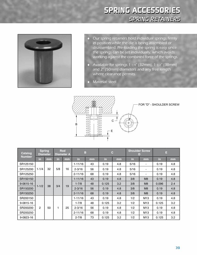
38 39
sPRING aCCessORIesspring retainers
♦ Our spring retainers hold individual springs firmly in position while the die is being assembled or disassembled. Pre-loading the spring is easy since the springs can be set individually, which avoids working against the combined force of the springs.
♦ Available for springs 1 1/4” (32mm), 1 1/2” (38mm) and 2” (50mm) diameters and any free length where clearance permits.
♦ Material: steel
B
E
FOR "D" - SHOULDER SCREW
C
Catalog Number
Spring Diameter
Rod Diameter A
B CShoulder Screw
DE
in mm in mm in mm in mm in mm in mm
SR125150
1-1/4 32 5/8 16
1-11/16 43 0.19 4.8 5/16 - 0.19 4.8
SR125200 2-3/16 56 0.19 4.8 5/16 - 0.19 4.8
SR125250 2-11/16 68 0.19 4.8 5/16 - 0.19 4.8
SR150150
1-1/2 38 3/4 19
1-11/16 43 0.19 4.8 3/8 M8 0.19 4.8
9-0615-16 1-7/8 48 0.125 3.2 3/8 M8 0.096 2.4
SR150200 2-3/16 56 0.19 4.8 3/8 M8 0.19 4.8
SR150250 2-11/16 68 0.19 4.8 3/8 M8 0.19 4.8
SR200150
2 50 1 25
1-11/16 43 0.19 4.8 1/2 M13 0.19 4.8
9-0815-16 1-7/8 48 0.125 3.2 1/2 M13 0.125 3.2
SR200200 2-3/16 56 0.19 4.8 1/2 M13 0.19 4.8
SR200250 2-11/16 68 0.19 4.8 1/2 M13 0.19 4.8
9-0823-16 2-7/8 73 0.125 3.2 1/2 M13 0.125 3.2

40 41
sPeCIaLTY ITemsaccu-Bend™ rotary Benders
sImPlIfyInG your bendInG Process WIth accu-bendtm rotary benders!
Accu-BendTM units include a tool steel Rocker set into a steel Saddle with a graphite plugged Aluminum-Bronze liner. Available in standard inch and metric sizes with Rocker diameters of 20mm–115mm (0.75” – 4.5”) and lengths of 50mm–900mm (2.0” – 35.0”), these units transfer the vertical motion of the press into a smooth one-motion rotation. The smooth rotation provides a rotary bend process which requires less tonnage and less strain on the material. The Accu-BendTM Rotary Bender can also include optional pre-configured mounting hole patterns.
The saddle liner is a bronze alloy chosen for the ability to hold up to a bearing load with little to no wear while the graphite plugs are included in the bronze liner to provide lubrication. Both Rockers and Saddles are machined for precision and interchangeability. Compact benders fit in tight places and are ideal for bending small tabs within a larger part. Specials can be manufactured for your custom needs as well when an off-the-shelf product doesn’t work for your application.
♦Holds ± 1/2 degree angle tolerance
♦Bends angles up to 120° for special part design and pre-hem applications
♦Decreases forming tonnage by 40 – 80% over wipe tooling and “V” dies
♦Forms channel bends in one hit by pairing two bends together
START POSITION BENd OVERBENdMATERIAL
SPRINGBACk

40 41
sPeCIaLTY ITemsmiscellaneous
formathane® urethane The Formathane® product line of urethane bars, rods, sheets, springs, film and strippers stands alone when compared to other urethane products offered in the market. Formathane® is formulated with the metalforming and fabricating user in mind to withstand the rigors of these difficult environments. Every day customers are putting it to the test and are finding double and triple life expectancies are more the norm than the exception with Formathane®. The higher than average performance is due to using premium grade urethane compounds, computer controlled production methods and stringent quality standards. Often used for springs, strippers, wear pads, vibration dampening, forming and part protection, Formathane® is offered in four durometers from 70 – 95A.
jIs sPrInGsAs a manufacturer of high quality springs in all standard ISO sizes, we also have available a line of true metric springs, in all the standard JIS (Japanese Industrial Standards) sizes and color load ratings. This extension of the spring line gives more options to customers with exacting requirements, making them available from the same reliable source as the inch springs. Manufactured in an optimal rectangular design and from a high strength chromium alloy material, these springs provide stability between load deflection and cycle life. The JIS product offering includes over 1,000 part numbers divided into five duty groups (colors), with fourteen diameters available per diameter and free lengths from 20mm to 300mm.
PunchesWe offer a comprehensive range of standard punches and die buttons in the basic, ball lock and variable precision series. Each component is made of quality heat treated tool steel which meets or exceeds ANSI standards. They are available in A2 high performance tool steel for toughness and economy, and M2, high speed steel, triple-tempered for long runs where abrasion resistance is required. Also available as a special option is PM4 which offers improved wear and impact characteristics ideal for optimum performance at high operating speeds.

42 43
miscellaneous
sPeCIaLTY ITems
surface mount ball bearInG assemblIes LEMPCO now offers a new low cost ball bearing component assembly alternative added to our die components guiding system product line. These new additions, Surface Mount Ball Bearing Assemblies, are mounted directly to the die holder and punch holder rather than the conventional method. These assemblies are available in 32mm, 38mm, 50mm and 60mm diameters, while lengths range from 100mm to 350mm, depending on diameter. Complete assemblies will include the necessary mounting bolts and dowel pins required for installation as well as optional tapped mounting holes to secure Stroke End Blocks. Surface Mount Ball Bearing Assemblies are available as stand-alone assemblies.
dIe accessorIesA complete line of inch and metric pressroom accessories, including fasteners, hoist rings, stripper bolts, punch holder shanks, roller stock guides, stock pushers, pry bars, ball bearing and die lubrication and pad retainers are available. With parts manufactured from heat-treated, high strength alloy steel and machined to precise tolerances, you can be sure they are inspected to assure uniform hardness, quality and dimensions.

42 43
custom capaBilities
sPeCIaLTY ITems
sPecIals to meet your eXact needsLEMPCO customization services will go to virtually any length to satisfy your needs. Now, the full range of answers to your requirements is at your command. It could be a simple modification or something quite exotic. Whatever your need, LEMPCO will work closely with you to select, design and manu-facture products to meet your demands, while providing cost-effective solutions.
♦ Finished outside diameters from 5/8" x 15" (15.9mm x 381mm) length to 5" x 60" (127mm x 1524mm) length ♦ Finished inside diameters Hardened Steel – 1/2" x 4" (12.7mm x 102mm) length to 3 5/8" x 14" (92mm x 356mm) length Bronze Plated Steel – 1/2" x 4" (12.7mm X 102mm) length to 4 1/2" x 9" (114mm x 228mm) length Solid Bronze (w/wo graphite plugs) – 5/8" x 4" (16mm x 102mm) length to 6 1/8" x 7 7/8" (156mm x 200mm) length ♦ 3-Axis milling with part lengths up to 48" (1219mm) ♦ 5-Axis prismatic machining ♦ Surface grinding up to 96" (2438mm) length x 17" (431mm) wide ♦ Hard turning Maximum outside diameter: 3 3/4" (95mm) Minimum inside diameter: 1/2" (12.7mm) ♦ Heat treating – alloy and low carbon steels up to 62HRC (size and carbon content dependent) ♦ Induction hardening 1050 steel, up to 5 1/4" (133mm) diameter and hardened to 58/62 HRC 52100 steel, up to 3 3/4" (95mm) diameter and hardened to 58/62 HRC ♦ CMM Machine Calypso programming software to quickly measure simple and complex parts, based on a CAD model or free form measurement Part weight capacity up to 3520 lbs. Measuring range (XYZ) – 39.4" x 63" x 23.6" Clearance under bridge – 29"
comPonents manufacturInG caPabIlItIes:
♦ Chrome Plating ♦ Copper Bronze Plating
sPrInGs manufacturInG caPabIlItIes: ♦ Outside diameters from 3/16" to 9 1/2" (4.8mm to 241mm) ♦ Free lengths from 1/2" to 90" (12.7mm to 2286mm) ♦ Round spring wire from 0.014" to 1.625" (.36mm to 41.3mm) ♦ Standard rectangular wire up to 0.408" x 0.469" (10.4mm x 11.9mm)
sPrInG coatInGs avaIlable:
High quality products, service and innovative development are key elements in our continued dedication to serving the needs of our customers.
♦ Plain, no paint ♦ Oiled ♦ Electroless Nickel ♦ Chrome
♦ Zinc ♦ Powder or E-coat paint ♦ Mil-spec coatings ♦ Cadmium
♦ Dacromet®
♦ Others on request
PlatInG servIces avaIlable:

© 2020 dayton lamIna corP. all rIGhts reserved. l-2000 6/20
www.daytonlamina.com