Introduction Crespo Vienna 2010.ppt -...
33
Dissemination of information for training – Vienna, 4-6 October 2010 EUROCODES Bridges: Background and applications 1 Introduction to design examples Pilar Crespo Pilar Crespo Roads Administration Ministry of Public Works (Spain)
Transcript of Introduction Crespo Vienna 2010.ppt -...

Dissemination of information for training – Vienna, 4-6 October 2010
EUROCODESBridges: Background and applications
1
Introduction to design examples
Pilar CrespoPilar CrespoRoads Administration
Ministry of Public Works (Spain)

Dissemination of information for training – Vienna, 4-6 October 2010 2
Introduction to design examples
Main example
EC1 EC7EC4EC3EC2 EC8
Dissemination of information for training – Vienna, 4-6 October 2010 3
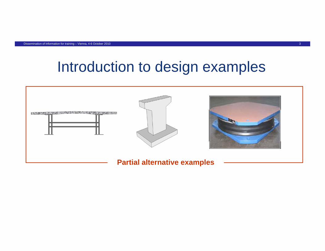
Introduction to design examples
Partial alternative examples

Dissemination of information for training – Vienna, 4-6 October 2010 4
Introduction to design examples
Partial alternative examples
EC2 EC4EC2 EC4

Dissemination of information for training – Vienna, 4-6 October 2010 5
Introduction to design examples
Partial alternative examples
EC1 EC2EC1 EC2

Dissemination of information for training – Vienna, 4-6 October 2010 6
Introduction to design examples
Partial alternative examples
EC8EC8
Dissemination of information for training – Vienna, 4-6 October 2010 7
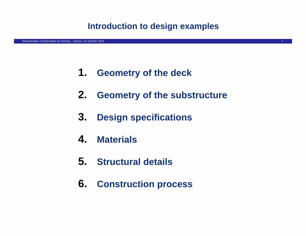
Introduction to design examples
1 Geometry of the deck1. Geometry of the deck
2. Geometry of the substructure
3. Design specifications
4. Materials
5 Structural details5. Structural details
6. Construction process
Dissemination of information for training – Vienna, 4-6 October 2010 8
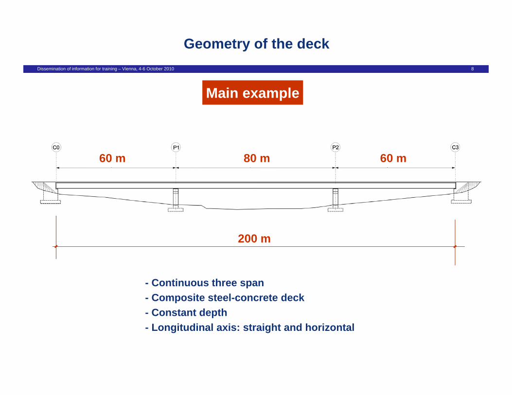
Geometry of the deck
Main example
80 m60 m 60 m
200 m
- Continuous three span- Composite steel-concrete deck- Constant depth- Longitudinal axis: straight and horizontal

Dissemination of information for training – Vienna, 4-6 October 2010 9
Geometry of the deck
Main example
3.3 m
12 m
Two girder composite deck

Dissemination of information for training – Vienna, 4-6 October 2010 10
Geometry of the deck
Main example
Two girder composite deck

Dissemination of information for training – Vienna, 4-6 October 2010 11
Geometry of the deck
Alternative deck (I)
Externally prestressed composite deck

Dissemination of information for training – Vienna, 4-6 October 2010 12
Geometry of the deck
Alternative deck (I)
Externally prestressed composite deck

Dissemination of information for training – Vienna, 4-6 October 2010 13
Geometry of the deck
Alternative deck (II)
3.3 m
12 m
Double composite deck

Dissemination of information for training – Vienna, 4-6 October 2010 14
Geometry of the deck
Alternative deck (II)
Double composite deck

Dissemination of information for training – Vienna, 4-6 October 2010 15
Geometry of the substructure
Piers
H = 10 m
Squat pier case
H = 40 m
High pier case

Dissemination of information for training – Vienna, 4-6 October 2010 16
Geometry of the substructure
Piers (I)
10 0 m10,0 m
Squat pier case
Dissemination of information for training – Vienna, 4-6 October 2010 17
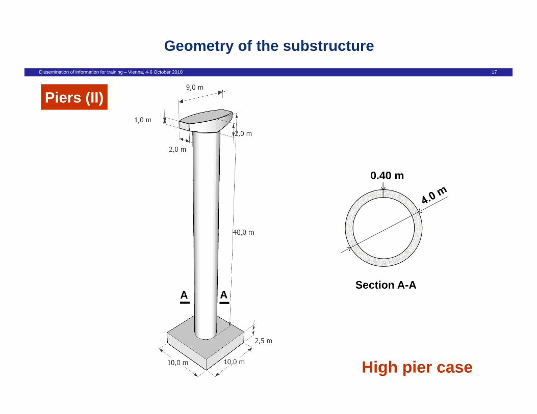
Geometry of the substructure
Piers (II)
0.40 m
Section A-AA A
Section A-A
High pier case

Dissemination of information for training – Vienna, 4-6 October 2010 18
Geometry of the substructure
Abutments

Dissemination of information for training – Vienna, 4-6 October 2010 19
Geometry of the substructure
Squat pier caseBearings (I)
Abutment AbutmentPierPier
- Seismic isolation system (two bearings per support)Triple Friction Pendulum bearings- Triple Friction Pendulum bearings
- Non-linear behaviour in both directions

Dissemination of information for training – Vienna, 4-6 October 2010 20
Geometry of the substructure
Bearings (II) High pier case
Abutment AbutmentPierPier
Limited ductile piers concept- Limited ductile piers concept- Articulations at piers- Bearings at abutments

Dissemination of information for training – Vienna, 4-6 October 2010 21
Geometry of the substructure
Special example for seismic designBearings (III)
H = 8 m
35 m23 m 23 m
Abutment Abutment
PierPier
- Ductile behaviour of piersp- Piers rigidly connected to the deck (H = 8 m; D = 1.2 m)- Bearings at abutments

Dissemination of information for training – Vienna, 4-6 October 2010 22
Introduction to design examples
1 Geometry of the deck1. Geometry of the deck
2. Geometry of the substructure
3. Design specifications
4. Materials
5 Structural details5. Structural details
6. Construction process

Dissemination of information for training – Vienna, 4-6 October 2010 23
Design specifications
- Design working life: 100 years
A f i ( i d )· Assessment of some actions (wind, temperature)· Minimum cover requirements for durability· Fatigue verifications

Dissemination of information for training – Vienna, 4-6 October 2010 24
Design specifications
- Design working life: 100 years
- Non-structural elements
· Parapets + cornices Parapets + cornices· Waterproofing layer (3cm)· Asphalt layer (8cm)
Dissemination of information for training – Vienna, 4-6 October 2010 25
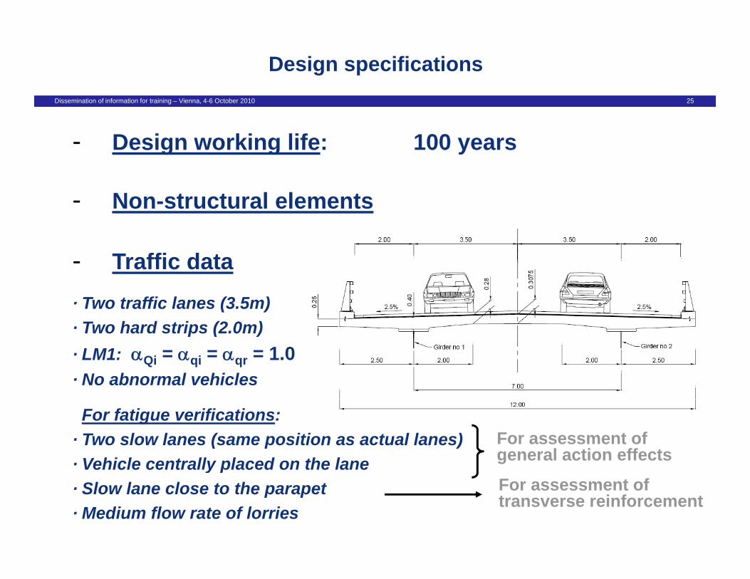
Design specifications
- Design working life: 100 years
T ffi d
- Non-structural elements
- Traffic data
· Two traffic lanes (3.5m)Two hard strips (2 0m)· Two hard strips (2.0m)
· LM1: Qi = qi = qr = 1.0· No abnormal vehicles
For fatigue verifications:· Two slow lanes (same position as actual lanes) · Vehicle centrally placed on the lane
For assessment of general action effectsy p
· Slow lane close to the parapet· Medium flow rate of lorries
For assessment of transverse reinforcement
Dissemination of information for training – Vienna, 4-6 October 2010 26
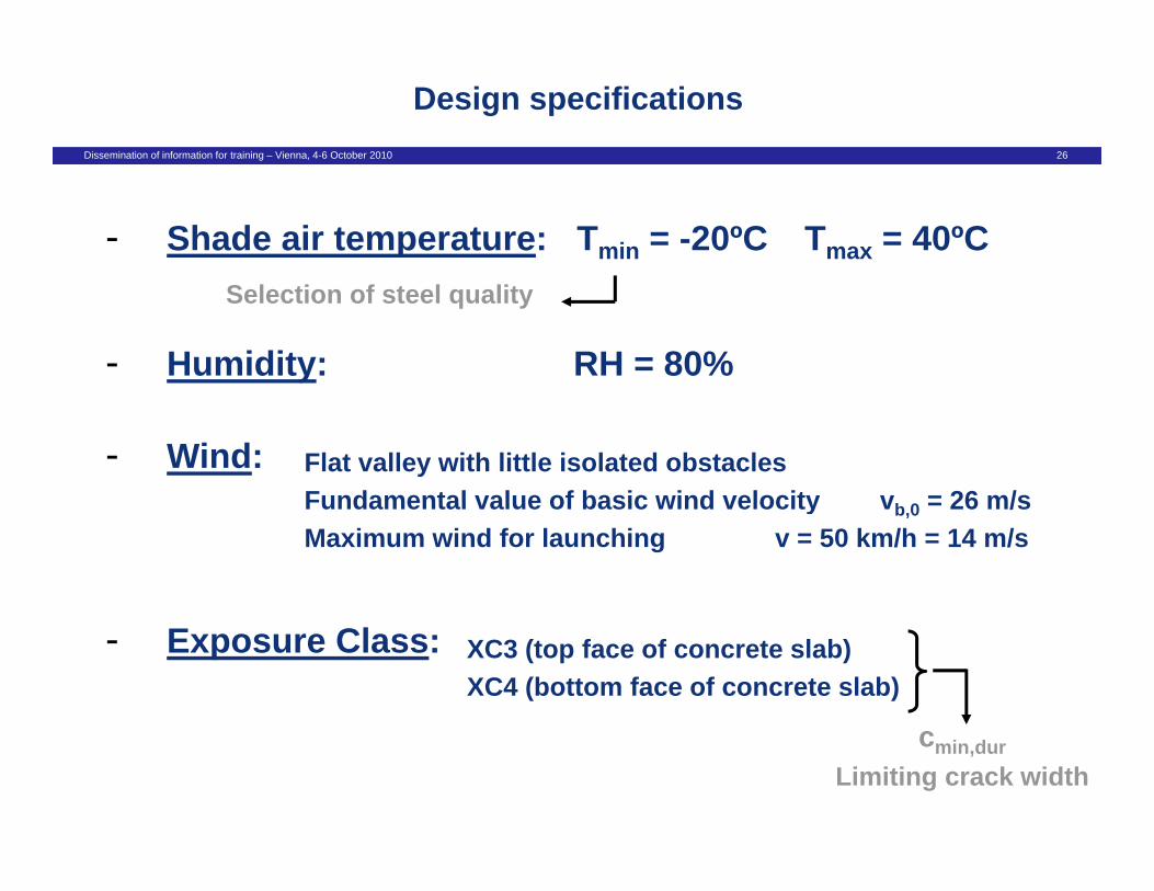
Design specifications
- Shade air temperature: Tmin = -20ºC Tmax = 40ºC
- Humidity: RH = 80%
Selection of steel quality
- Wind: Flat valley with little isolated obstaclesFundamental value of basic wind velocity v = 26 m/sFundamental value of basic wind velocity vb,0 = 26 m/sMaximum wind for launching v = 50 km/h = 14 m/s
- Exposure Class: XC3 (top face of concrete slab)XC4 (bottom face of concrete slab)
cmin,durLimiting crack width

Dissemination of information for training – Vienna, 4-6 October 2010 27
Design specifications
- Soil conditions: No deep foundation is neededSettlement P1: 30 mmSettlement P1: 30 mm
- Seismic data: Bridge of medium importance (I = 1.0)
S i i i l tiSeismic isolation case
Ground type BPeak ground acceleration: agR = 0.40 g
Limited ductile piers case (q = 1.5)
Ground type BypPeak ground acceleration: agR = 0.30 g
Ductile piers case (q = 3.5)
Ground type CPeak ground acceleration: agR = 0.16 g
Dissemination of information for training – Vienna, 4-6 October 2010 28
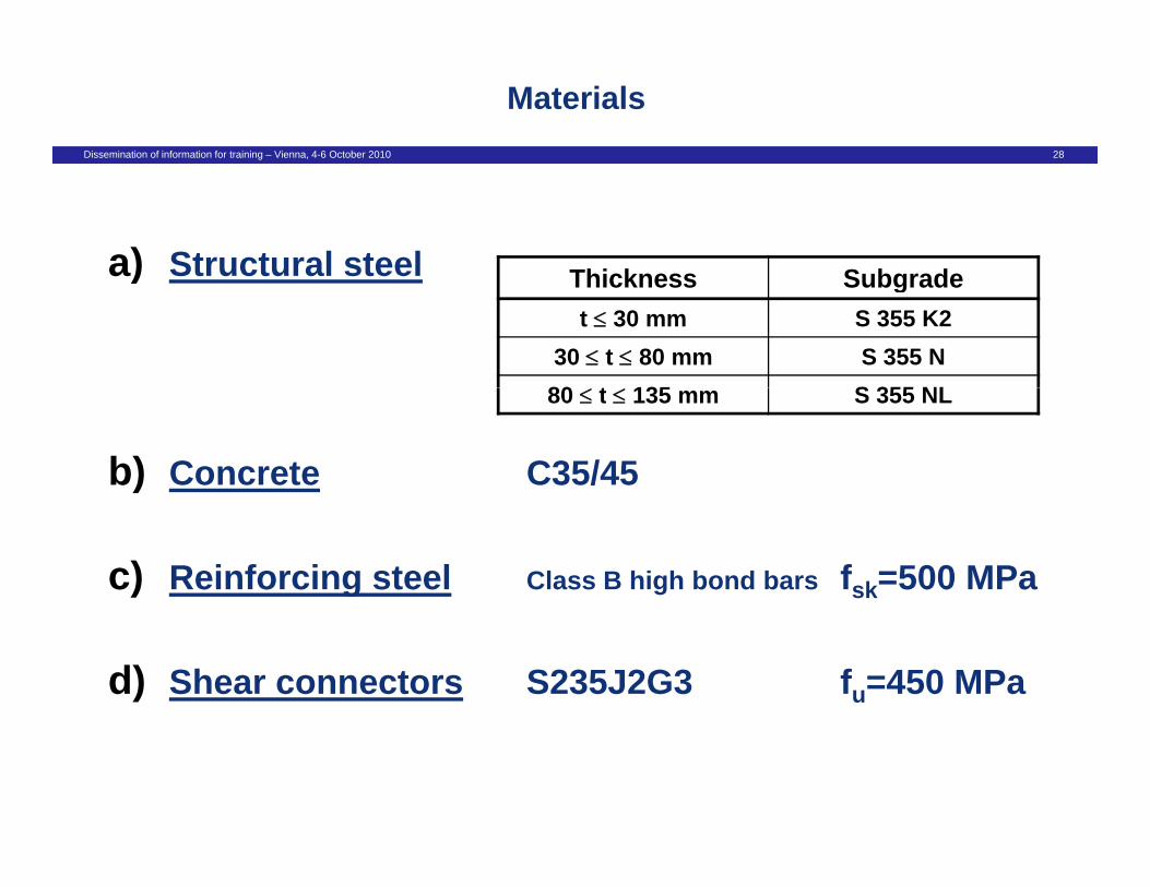
Materials
a) Structural steel Thickness Subgradea) St uctu a stee Thickness Subgradet 30 mm S 355 K2
30 t 80 mm S 355 N80 t 135 S 355 NL
b) Concrete C35/45
80 t 135 mm S 355 NL
c) Reinforcing steel Class B high bond bars fsk=500 MPa
d) Shear connectors S235J2G3 fu=450 MPa

Dissemination of information for training – Vienna, 4-6 October 2010 29
Introduction to design examples
1 Geometry of the deck1. Geometry of the deck
2. Geometry of the substructure
3. Design specifications
4. Materials
5 Structural details5. Structural details
6. Construction process

Dissemination of information for training – Vienna, 4-6 October 2010 30
Structural details
Structural steel
Upper flange: 1000 mm x 120 mmLower flange: 1200 mm x 120 mmWeb: 26 mm
Support cross-sectionCross-bracing: built-up welded
Upper flange: 1000 mm x 40 mmpp gLower flange: 1200 mm x 40 mmWeb: 18 mm Cross-bracing: IPE-600Cross bracing: IPE 600
Mid-span cross-section

Dissemination of information for training – Vienna, 4-6 October 2010 31
Structural details
Slab reinforcement
Dissemination of information for training – Vienna, 4-6 October 2010 32
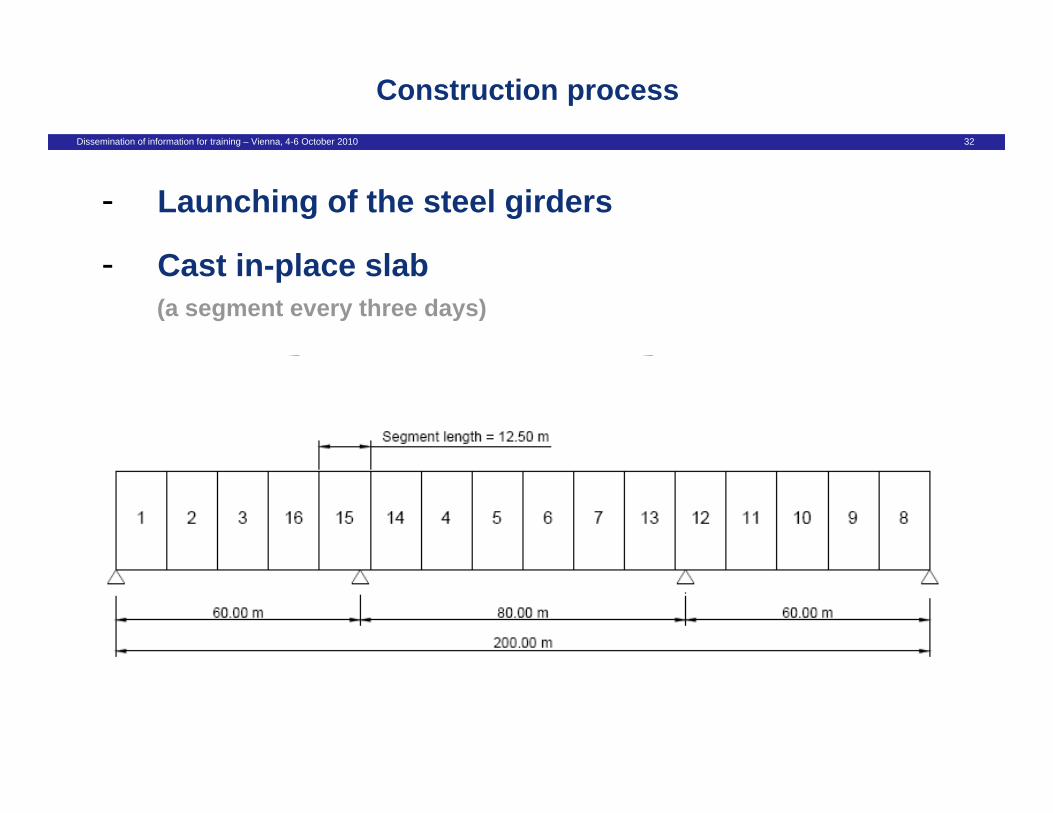
Construction process
C
- Launching of the steel girders
- Cast in-place slab
- (a segment every three days)(a segment every three days)

Dissemination of information for training – Vienna, 4-6 October 2010 33
EN1990Basis of Design
EC1 EC7EC4EC3EC2 EC8