Introduction - Asia-Pacific Telecommunity · Web viewThis Report provides technical guideline of...
15
APT REPORT ON FRONTHAUL/BACKHAUL USING MILLIMETER-WAVE RADIO OVER FIBER TECHNOLOGIES No. APT/ASTAP/REPT-25 Edition: March 2017 Adopted by The 28 th APT Standardization Program Forum (ASTAP-28)
-
Upload
trinhxuyen -
Category
Documents
-
view
219 -
download
2
Transcript of Introduction - Asia-Pacific Telecommunity · Web viewThis Report provides technical guideline of...
APT REPORT
ON
FRONTHAUL/BACKHAUL USING MILLIMETER-WAVE RADIO OVER FIBER TECHNOLOGIES
No. APT/ASTAP/REPT-25Edition: March 2017
Adopted byThe 28th APT Standardization Program Forum (ASTAP-28)
6 – 10 March 2017, Bangkok, Thailand
(Source: ASTAP-28/OUT-06)

Contents1. Introduction...........................................................................................................................32. Scope.....................................................................................................................................33. References.............................................................................................................................34. Abbreviations and acronyms.................................................................................................45. System architecture...............................................................................................................46. System demonstration and discussion...................................................................................67. Conclusion...........................................................................................................................11
APT/ASTAP/REPT-25 Page 2 of 11

1. Introduction The aim of this contribution is to propose Radio over Fiber (RoF) for radio signal delivery over optical fiber networks, and Radio on Radio over Fiber (RoRoF) for transportation of microwave (MW) signals on a millimeter-wave (MMW) carrier over optical fiber networks. Future mobile communication technology, so-called 5G mobile, connection speed to each user will be achieved 10 Gb/s. To realize such high-speed connection, a carrier frequency of the radio should be increased to millimeter-wave band. In addition, high throughput for enhancing user experiences requires to make cell-size/coverage by each radio base station be smaller: small cell configuration. Particularly in 5G, even in fourth-generation (4G) mobile communication, coordination of multi base stations is implemented for enhancement of functionality of the mobile network. In the scenario, a function of the base stations should be separated to the combination of a baseband signal processing unit and an RAU. The baseband unit is connected to many RAUs for reduction of the cost, realization of the coordination multi-point connection, and improvement of the signal service quality at the edge of the cell. Therefore, a large number of the RAUs are connected and controlled by the baseband unit. In 5G era, the connection/link technology between the baseband unit and RAUs, so-called mobile fronthaul (MFH), should have large capacity and low latency to optimize the throughput. In addition, mobile backhaul (MBH) for the connection between the baseband unit and the core/metro networks should have the capacity much larger than that for the MBF. However, wireline connections might not be deployed somewhere owing to cost and geographical issued under small-cell configurations.The RoF and RoRoF have a feature on seamless conversion between the optical (wireline) signal and a radio (wireless) signal. A part of the RoF technologies has been already utilized as an MFH link, and has been discussed the possibility for seamless integration to a fiber to the home (FTTH), and therefore, the RoF has possible high-capacity feature. On the other hand, the RoRoF has features as low latency of a media conversion and avoidance of the frequency interferences owing to the encapsulation of the incumbent services to the millimeter-wave carriers. High-speed optical fiber communication technology, e.g. high-speed O/E conversion can generate the millimeter-wave carriers. A simple detector such as an envelope detector operating in the millimeter-wave bands can easily convert the received millimeter-wave signals to the microwaves. This contribution focuses on applications of RoF/RoRoF to the access networks including MFH/MBH links.
2. Scope This Report provides technical guideline of the access networks using millimeter-wave (MMW) radio by RoF and RoRoF technologies in the wired and wireless seamless access communication systems. Experimental demonstration and deployment scenario of these technologies for future access networks including MFH/MBH links are also addressed as examples.
3. References [APT/ASTAP/REPT-03(Rev.4)]: APT Report (2013), Characteristics and requirement of
optical and electrical components for millimeter-wave Radio on Fiber systems
[APT/ASTAP/REPT-04]: APT Report (2011), Technology trends of telecommunications above 100 GHz
[APT/ASTAP/REPT-11]: APT Report (2013), Wired and wireless seamless connections using millimeter-wave Radio over Fiber technology for resilient access networks
APT/ASTAP/REPT-25 Page 3 of 11
[APT/ASTAP/REPT-19]: APT Report (2015), Integration of Radio over Fiber with WDM PON for seamless access communication system
[APT/ASTAP/REPT-20]: APT Report (2015), RoF relay link for indoor communication systems
[ITU-T G. Suppl.55]: ITU-T G-series Supplement RoF on Radio-over-fiber (RoF) technologies and their applications
[ITU-R F.2106-1] Fixed service applications using free-space optical links[3GPP TS 36.104 version 10.9.0 release 10]: Evolved Universal Terrestrial Radio Access (E-
UTRA); Base Station (BS) radio transmission and reception
4. Abbreviations and acronyms This Report uses the following abbreviations and acronyms:BER Bit error rateCS Central stationDSP Digital signal processingED Envelop detectorEVM Error vector magnitudeEDFA Erbium-doped fiber amplifierLNA Low noise amplifierLTE Long Term EvolutionLTE-A Long Term Evolution-AdvancedLO Local oscillatorMBH Mobile backhaulMFH Mobile fronthaulMMW Millimeter-waveMW MicrowaveMZM Mach–Zehnder interferometer-type optical modulatorOBEF Optical band-elimination filterOBPF Optical bandpass filterOLT Optical line terminalPA Power amplifierPD PhotodiodeQAM Quadrature amplitude modulationQPSK Quadrature phase-shift keyingRAU Remote antenna unitRoF Radio over fiberRoR Radio on radioRoRoF Radio on radio over fiberSHD Self-homodyne detectorTLS Tunable laser sourceVSA Vector signal analyzerVSG Vector signal generatorWiFi Wireless Fidelity
APT/ASTAP/REPT-25 Page 4 of 11
5. System architecture 5.1 System overviewTo deliver a microwave radio signal to remote sites, an optical fiber network is a promising because of its low transmission loss feature and broad bandwidth of available waveband. However, the optical fiber cannot be deployed in some places, such as a rural area, a mountain area, and an opposite side on the big river and so on, due to geographical and cost issues. In the scenario, an MMW is a candidate to realize MFH/MBH links without radio interferences to the existing MW radio systems. A RoF can easily realize the seamless convergence between optical and radio signals. On the other hand, signal generation and transmission techniques are indispensable for delivery of the MW signal on the MMW signal. This is so-called radio on radio (RoR): the MW radio systems signals on the MMW carrier. Great advantage of the RoR is to avoid the radio interferences to existing microwave systems because the transmitted carrier is just MMW signal. However, in general, the MMW has a relative high atmospheric attenuation coefficient, so the signal cannot be delivered through the air transmission. A RoRoF is one of the solutions to deliver the microwave signal to the location using an optical fiber network and the over-the-air transmission. A central station (CS) generates a RoRoF signal that is suitable for transmission over the optical fiber. By signal conversion from the RoRoF signal to the MMW RoR signal, the MMW radio transmission can be performed in the zone where an optical fiber cannot be deployed. Finally, a conversion between the MMW RoR and the microwave system signal is performed at the remote site. The RoRoF system helps realizing the microwave radio systems signal delivery to the remote sites without radio signal interferences.
Figure 1 Mobile backhaul/fronthaul using millimeter-wave radio connected to optical fiber network.
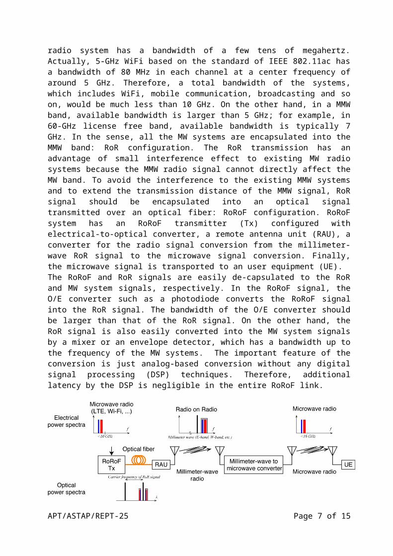
5.2 Concept of Radio on Radio over FiberFigure 2 shows a conceptual schematic of the RoRoF technology. The RoR is an encapsulation technology of radio systems in a microwave (MW) band into MMW radio carrier. In general, each radio system has a bandwidth of a few tens of megahertz. Actually, 5-GHz WiFi based on the standard of IEEE 802.11ac has a bandwidth of 80 MHz in each channel at a center frequency of around 5 GHz. Therefore, a total bandwidth of the systems, which includes WiFi, mobile communication, broadcasting and so on, would be much less than 10 GHz. On the other hand, in a MMW band, available bandwidth is larger than 5 GHz; for example, in 60-GHz license free band, available bandwidth is typically 7 GHz. In the sense, all the MW systems are encapsulated into the MMW band: RoR configuration. The RoR transmission has an advantage of small interference effect to existing MW radio systems because the MMW radio signal cannot directly affect the MW band. To avoid the interference to the existing MMW systems and to extend the transmission distance of the MMW signal, RoR signal should be encapsulated into an optical signal transmitted over an optical fiber: RoRoF configuration. APT/ASTAP/REPT-25 Page 5 of 11

RoRoF system has an RoRoF transmitter (Tx) configured with electrical-to-optical converter, a remote antenna unit (RAU), a converter for the radio signal conversion from the millimeter-wave RoR signal to the microwave signal conversion. Finally, the microwave signal is transported to an user equipment (UE).The RoRoF and RoR signals are easily de-capsulated to the RoR and MW system signals, respectively. In the RoRoF signal, the O/E converter such as a photodiode converts the RoRoF signal into the RoR signal. The bandwidth of the O/E converter should be larger than that of the RoR signal. On the other hand, the RoR signal is also easily converted into the MW system signals by a mixer or an envelope detector, which has a bandwidth up to the frequency of the MW systems. The important feature of the conversion is just analog-based conversion without any digital signal processing (DSP) techniques. Therefore, additional latency by the DSP is negligible in the entire RoRoF link.
Figure 2 Conceptual diagram of proposed radio on radio over fiber system.
6. System demonstration and discussion 6.1 Configuration of RoRoF transmission with single microwave radio systemFigure 3 shows an example of the RoRoF signal transmission by a MMW radio at a frequency of 92 GHz. In an optical MMW generator, a fiber laser (FL) connected with a dual-parallel Mach-Zehnder interferometer-type modulator (DPMZM) provides an optical two-tone signal with a separation of a quadrupled input frequency generated by a local oscillator (LO). An optical band elimination filter (OBEF) suppresses unwanted optical carrier component generated by the modulation in the DPMZM. An erbium-doped fiber amplifier (EDFA) followed by an optical band pass filter, which is utilized as a suppression of amplified spontaneous emission noise from the EDFA, optimizes an output optical power from the optical MMW generator. The optical two-tone signal with a frequency separation of 94.1 GHz, which is quadruple of input signal to the DPMZM from the LO at a frequency of 23.525 GHz, is modulated by an MZM with the signal from a vector signal generator. The signal waveform of the VSG is based on LTE-A signal compliant to the 3GPP standard with 3 carrier components (CCs) at a center frequency of around 2 GHz. The modulation format of a quadrature phase-shift keying (QPSK), 16-ary quadrature amplitude modulation (QAM), and 64-QAM is used in this evaluation. The modulated two-tone signal is boosted up by the EDFA, and then, the signal is transmitted over an optical fiber. After the transmission, a PD converts a RoRoF signal with a 2-GHz LTE-A signal over the MMW signal at a corresponding frequency of 94.1 GHz to the RoR signal. A power amplifier (PA) connected to an antenna amplifies an MMW radio power to irradiate to the air. After 5-m transmission over the air, an antenna followed by a low noise amplifier (LNA) collects and optimizes the MMW signal. An ED regenerates the LTE-A MW signal from the 94.1-GHz RoR signal. The converted MW signal
APT/ASTAP/REPT-25 Page 6 of 11
is amplified by the LNA in the MW band, and then, a vector signal analyzer (VSA) demodulates and analyzes MW waveform to evaluate signal quality.
Figure 3 LTE-Advanced signal transport on 94-GHz millimeter-wave carrier in RoRoF system.
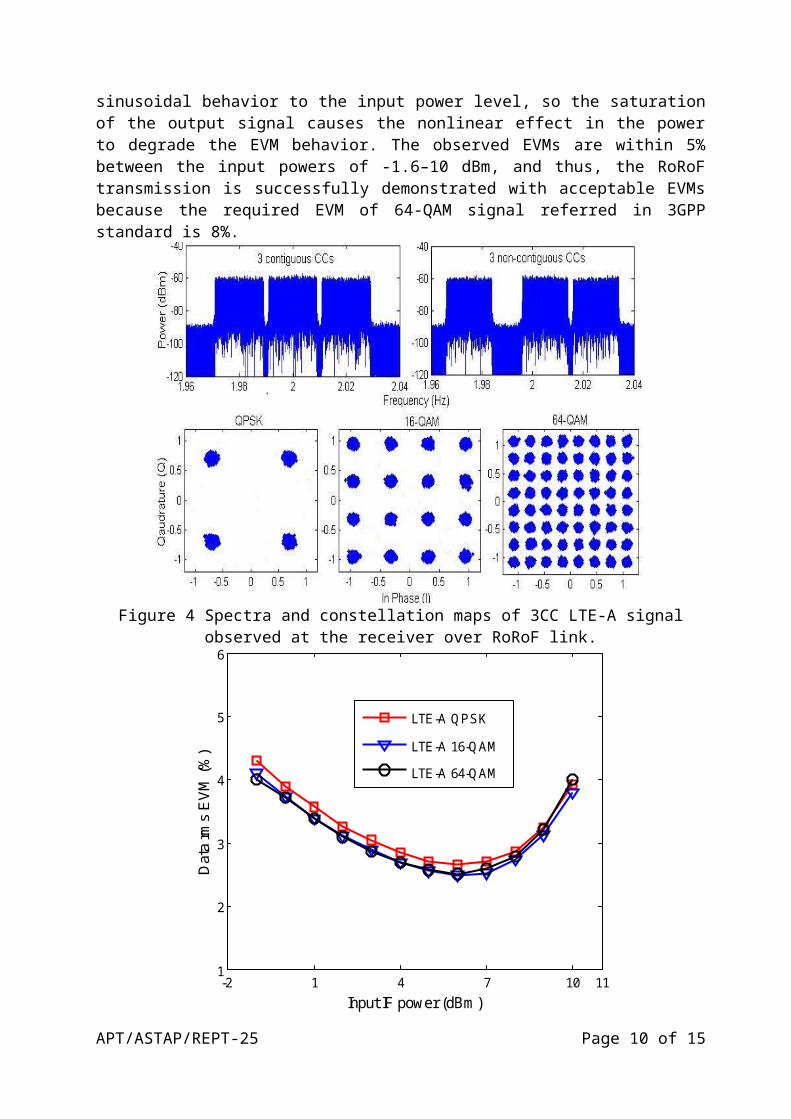
6.2 Discussion o RoRoF transmission with single microwave systemFigure 4 shows an obtained electrical spectra and a constellation map observed at the VSA. In this setup, the LTE-signal used as a signal under test is formed with 3 CCs under different carrier configuration: contiguous and non-contiguous configurations. The spectra in both cases clearly show a good separation of each CC with a signal to noise ratio greater than 25 dB. The observed constellation maps for QPSK, 16-QAM and 64-QAM has a clear symbol separation with similar error vector magnitudes (EVMs) of approximately 4%. This result shows that the RoRoF and RoR signal transmission is successfully demonstrated.An input power level of the MW signal to the MZM is one of the important factors in the system because this power directly reflects to a signal to noise ratio of the MW signal. In addition, the MZM has nonlinear response in the input power level generally. Thus, the evaluation and optimization of the input power level is required. Figure 5 shows the observed EVM dependence on the input power level to the MZM. The observed behavior of the EVMs has a so-called bathtub curve with the bottom of the EVM of 2.6% at the input level of 6 dBm. Below the level of 6 dBm, the degradation of the EVM is caused by deficient input level to the MZM. On the other hand, above the level of 6 dBm, the observed EVMs are drastically degraded. This could be caused by the nonlinear response of the MZM. In general, a transfer function of the MZM has a squared sinusoidal behavior to the input power level, so the saturation of the output signal causes the nonlinear effect in the power to degrade the EVM behavior. The observed EVMs are within 5% between the input powers of -1.6–10 dBm, and thus, the RoRoF transmission is successfully demonstrated with acceptable EVMs because the required EVM of 64-QAM signal referred in 3GPP standard is 8%.
APT/ASTAP/REPT-25 Page 7 of 11
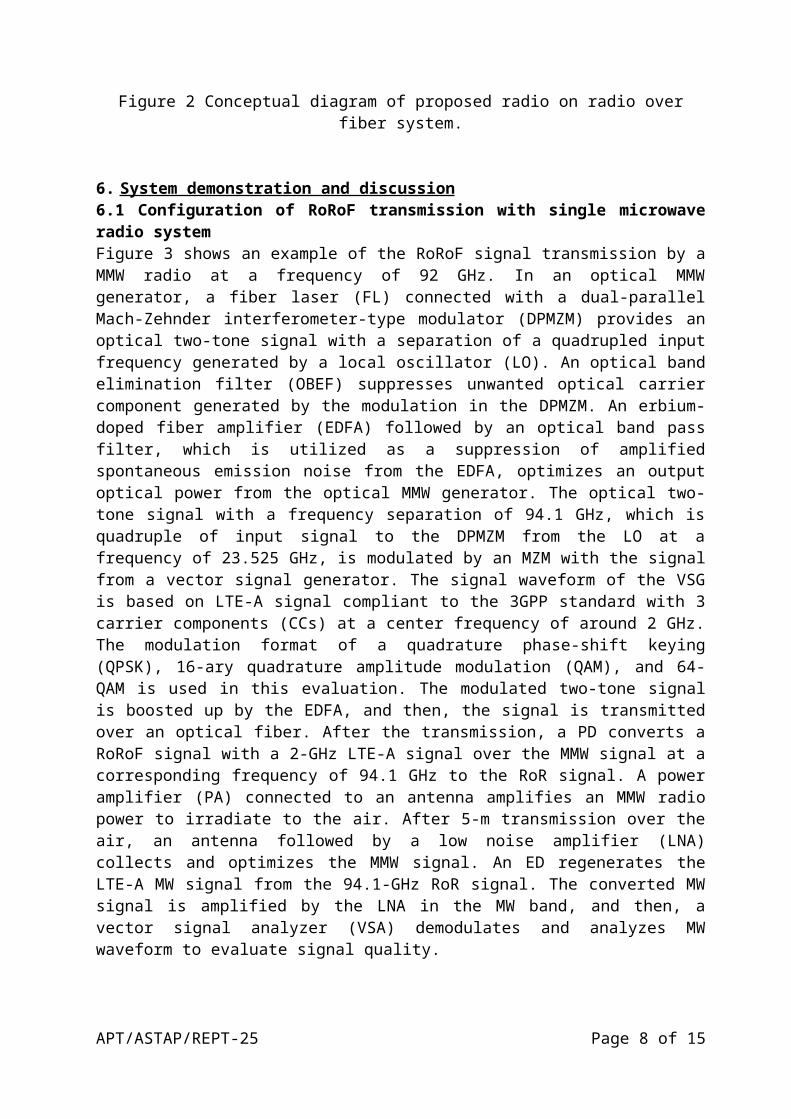
Figure 4 Spectra and constellation maps of 3CC LTE-A signal observed at the receiver over RoRoF link.
-2 1 4 7 10 111
2
3
4
5
6
Input IF power (dBm)
Dat
a rm
s E
VM
(%)
LTE-A QPSK
LTE-A 16-QAM
LTE-A 64-QAM
Figure 5 EVM dependence on various IF powers input to the MZM.
6.3 Configuration of RoRoF transmission with multiple microwave radio systemsGeneral configuration for demonstration of RoRoF signal transmission with multiple microwave radio signals is based on the configuration shown in Fig. 3. To employ the multiple radio signals, generally, the sensitivity and spurious free dynamic range (SFDR) of the MMW-to-MW converter is more important than that for single microwave radio signal transmission. From this point of view, a self-homodyne detector (SHD) would be equipped as the MMW-to-MW converter used as substitute for the ED in Fig. 3.
APT/ASTAP/REPT-25 Page 8 of 11

Figure 6 shows a block diagram of the demonstration setup for LTE-A and WiFi signals transmission via RoRoF link. In a CO, the configuration is same shown in Fig. 4 but input RF signals are used with an LTE-A downlink signal and an IEEE802.11ac signal combined with an RF combiner. The transmission of RoRof signal and MMW signal over the air are similar described above, and then, the MMW-to-MW converter captures the RoR signal in the MMW band. The MMW signal is amplified by an LNA, and then, is input to an SHD. The SHD converts incoming RoR signal in the MMW band to the MW signals. The LNA for the MW signal optimizes the power level of the signal, and finally, the VSAs followed by an RF divider demodulate the LTE-A and IEEE802.11ac signals. The detailed configuration of the SHD is shown in Fig. 7. Incoming MMW signal is split into two components by a divider. One component is optimized on its power level by an attenuator (ATT) and a PA used as a LO. A phase of the other component from the divider is optimized by a variable phase shifter (VPS) with isolators (ISOs), and is utilized as a signal. Finally, these two components are mixed down to the frequency-downconverted signal by a double balanced mixer (DBM). When the RoRoF signal is input to the SHD, encapsulated microwave signal is provided from the DBM output. The obtained SFDR is also shown in Fig. 7, and is achieved to be 70 dB•Hz2/3 as compared to the SFDR of 58 dB•Hz2/3 by the ED. 12-dB improvement could be accepted for the multiple radio signal transmission via RoRoF link.
Figure 6 Configuration of RoRoF signal transmission with multiple radio signals using the SHD.
Figure 7 (left) Detailed block diagram of the SHD and (right, blue) obtained SFDR of fundamental and IMD3. (right red) The SFDR using the ED is shown as a reference.
APT/ASTAP/REPT-25 Page 9 of 11
6.4 Discussion of RoRoF transmission with multiple microwave radio systemsFigure 8 shows the obtained electrical power spectrum measured at the output of the SHD for simultaneous transmission with the LTE-A and IEEE802.11ac signals. It should be noted that the LTE-A signal has two carrier components under carrier aggregation configuration. Second-order intermodulation distortion (IMD2) components are clearly observed, but these components is located far from the desired component in the frequency, so applying suitable bandpass filter can suppress these components. Third-order intermodulation distortion (IMD3) components are near from the desired LTE-A and IEEE802.11ac components. As the spurious suppression ratio is observed greater than 25 dB, interference effects by the IMD3 to the desired components could be negligible.For the LTE-A signal evaluation after the RoRoF transmission, constellation maps and their EVMs are shown in Fig. 9 with different carrier aggregation conditions. The obtained EVM behavior with various transmitter power, which is defined by the input power at the input port of the RF combiner, differs with the order of the multilevel modulation of 16-QAM and 64-QAM. Optimized power of +4 dBm provides the EVM less than 4% in each carrier aggregation conditions. The obtained EVM is within the regulated limit of 12.5% for 16-QAM and 8% for 64-QAM, and therefore, the RoRoF transmission is successfully demonstrated on LTE-A signals.On the other hand, on the IEEE802.11ac signal, 256-QAM signal with the signal bandwidth of 40 MHz is also successfully transmitted (Fig. 10). When the WiFi transmitter power measured at the input port of the RF combiner is 10 dBm, the obtained EVMs with various co-transmitted LTE-A transmitter power is within the regulation limit of -30 dB at the co-transmitted power less than 5 dBm. It should be noted that 5-dBm output of the LTE-A signal is optimal power for best EVM performance shown in Fig. 9. Therefore, the LTE-A and WiFi signal co-transmission over the RoRoF configuration is successfully demonstrated using the optical MMW generator and the SHD.
Figure 8 Electrical power spectrum measured after the SHD.
APT/ASTAP/REPT-25 Page 10 of 11

Figure 9 (left) Observed power spectra and constellation maps of LTE-A signal with different carrier aggregation conditions and (right) obtained EVMs for (red) interband 1 and (blue)
interband 2 configurations.
Figure 10 (left) obtained power spectrum, (middle) constellation maps, and (right) EVMs for WiFi IEEE802.11ac simultaneously transmitted with LTE-A signal. The EVMs behavior with
the WiFi transmitter power of 10 dBm is plotted by the transmitter power for the LTE-A launched into the RF combiner.
7. Conclusion The configuration and proof-of-concept demonstration of the RoF and RoRoF technologies for application to the access network including the MFH/MBH links are shown. The MMW RoRoF has possibility for LTE and LTE-A signal delivery with conformance to the regulations. In addition, multi radio signal transmission is also capable with WiFi and mobile communication signals. This Report shows the technical guidance of RoF and RoRoF technology for application to multi radio signal delivery over optical fiber and MMW links.
APT/ASTAP/REPT-25 Page 11 of 11