INTRODUCTION AND PURPOSE OF THE COURSE · INTRODUCTION AND PURPOSE OF THE COURSE ... 17+ with IDOT...
105
2/16/2015 1 INTRODUCTION AND PURPOSE OF THE COURSE NBI Calibration 2015 2/16/2015 C-2 Introduction Class Instructor: Mike Cima Background: Over 25 years of bridge related structure experience 17+ with IDOT BB&S, 7+ with HLR Engineering (Elgin / Springfield / Romeoville) Past experience includes bridge inspection, planning, design and policy development Inspection background includes most types of structures, large and small Licensed PE and SE in Illinois 2/16/2015
Transcript of INTRODUCTION AND PURPOSE OF THE COURSE · INTRODUCTION AND PURPOSE OF THE COURSE ... 17+ with IDOT...

2/16/2015
1
C-1
INTRODUCTION AND
PURPOSE OF THE COURSE
NBI Calibration 2015 2/16/2015
C-2
Introduction
Class Instructor: Mike Cima
Background:
Over 25 years of bridge related structure experience
17+ with IDOT BB&S, 7+ with HLR Engineering
(Elgin / Springfield / Romeoville)
Past experience includes bridge inspection,
planning, design and policy development
Inspection background includes most types of
structures, large and small
Licensed PE and SE in Illinois
2/16/2015

2/16/2015
2
C-3
Introduction
Focus of the Class
Consistent application of
current policies
Discuss new and recently
revised policies
Discuss current procedures
with “room for improvement”
Chapter 3 of the Structural
Services Manual - Inspection
(www.dot.state.il.us/bridges/brmanuals.html)
2/16/2015
C-4
Introduction
Material To Be Covered
Typical items reported on
IDOT inspection forms
Procedures for inspecting,
completing forms, and
reporting information
Determining Condition
Ratings of various bridge
elements
Feedback from QA process
audits regarding common
findings and deficiencies
2/16/2015

2/16/2015
3
C-5
Introduction
Course Objectives:
1. Improve the understanding of key indicators
affecting condition ratings to achieve consistent &
accurate reporting of bridge inspection data
2. Increasing awareness of existing deficiencies in
inventory data so they can be corrected if
necessary
3. Update participants on changes in policy and
inspection methods
2/16/2015
C-6
Introduction
Why Do We Inspect Bridges?
To ensure public safety
Inspection of highway bridges is mandated by the NBIS
Inspection data serves as a programming tool to
allocate funding and resources. The Sufficiency Rating,
which determines the eligibility for funding, is
calculated using inspection & inventory data.
Deficiencies noted during inspections identify
maintenance needs
2/16/2015

2/16/2015
4
C-7
Introduction
What is Calibration, and why do we do it?
Quality of information in the database is important.
Distribution of bridge funds can be affected.
Decisions (permits, detours, etc.) are made based on this information.
Consistency across various bridge programs is needed.
The rating of a bridge in “poor” condition should not vary based on the
location of the bridge and who inspected it.
There are several hundred inspectors involved in bridge
inspections in Illinois.
There needs to be a means to establish and maintain consistent
standards for determining the condition of the State’s bridges.
The NBIS includes a requirement for refresher training of
bridge inspectors – this class fills that requirement.
2/16/2015
C-8
Introduction
2/16/2015
Hypothetical Example of Condition Ratings Reported
by “Un-Calibrated” Inspectors
Without calibration
training, interpretation
of rating criteria and
policies can vary
greatly.
Inspectors may be
unaware of new or
revised policies.
Some inspectors may
not be following
policy.

2/16/2015
5
C-9
Introduction
2/16/2015
Typical Example of Condition Ratings Reported by
Inspectors
Process audits of
agencies with well-trained
inspectors find agreement
with recorded Condition
Ratings within “1” rating
category.
Calibration training is
intended to improve the
consistency of reported
Condition Ratings by
clarifying the boundaries
between ratings.
C-10
Introduction
2/16/2015
Idealized Example of Condition Ratings Reported by
Calibrated Inspectors
The desired result of
calibrating inspectors to
common standards is
less variability in the
reported data.
Some variation will still
exist, but almost all
reported Condition
Ratings would be within
“1” rating category of the
targeted “correct” rating.

2/16/2015
6
C-11
Introduction
How do we achieve consistent ratings
between a group of inspectors on a
given structure?
1. Use consistent inspection practices
2. Use uniform rating guidelines
2/16/2015
C-12
Introduction
1. Bridge Inspector's
Reference Manual
(BIRM) (Dec. 2012)
Provides detailed
information for bridge
inspection
Available at no cost
Establishes “consistent
inspection practices”
https://www.nhi.fhwa.dot.gov
2/16/2015

2/16/2015
7
C-13
Introduction
2. Structure Information and
Procedure Manual
Detailed information for coding of
ISIS data items
Primary guidance for determining
the Condition Rating of bridge
elements (“establishes uniform
rating guidlines”)
Course focuses on the application
of these guidelines
Watch for revisions on IDOT’s web
site / subscription service
(www.dot.state.il.us/isis/structinfo.html)
2/16/2015
C-14
Introduction
Code General Description
N Not Applicable
9 Excellent (New) Condition
8 Very Good Condition - No problems noted.
7 Good Condition - Some minor problems.
6 Satisfactory Condition - Structural elements show some minor deterioration.
5 Fair Condition - All primary structural elements are sound but may have minor section loss, cracking, spalling or
scour.
4 Poor Condition - Advanced section loss, deterioration, spalling or scour. (A drop in Item 59, 60 or 62 to a rating of 4
or lower or Item 58 to a 3 or lower will require a damage inspection by the Bureau of Bridges and Structure to
determine any change in the inventory and operating ratings, items 66 and 64).
3 Serious Condition - Loss of section, deterioration, spalling or scour have seriously affected primary structural
components. Local failures are possible. Fatigue cracks in steel or shear cracks in concrete may be present.
2
Critical Condition - Advanced deterioration of primary structural elements. Fatigue cracks in steel or shear cracks
in concrete may be present or scour may have removed substructure support. It may be necessary to close the
bridge until corrective action is taken. (When a bridge component is appraised at this level, a special inspection of
that component is required at intervals not to exceed 6 months as directed by the Bureau of Bridges and
Structures. The Bureau of Bridges and Structures must be notified immediately).
1 "Imminent" Failure Condition - Major deterioration or section loss present in critical structural components or
obvious vertical or horizontal movement affecting structure stability. Bridge is closed to traffic but corrective action
may put it back in service with load restrictions.
0 Failed Condition - Out of service; beyond corrective action.
2/16/2015

2/16/2015
8
C-15
Introduction
Code: Description: Commonly Employed Actions:
9 EXCELLENT CONDITION •Preventive Maintenance.
•Little concern from a safety perspective. 8 VERY GOOD CONDITION
7 GOOD CONDITION
6 SATISFACTORY CONDITION •Preventive Maintenance and/or Repairs.
•May be possible to “save” elements at this
stage of deterioration with maint. or repair. 5 FAIR CONDITION
4 POOR CONDITION
• Rehabilitation or Replacement.
•Safety concerns & Load Rating Inspections.
• Traffic disruptions due to load postings
and/or detours possible.
3 SERIOUS CONDITION
2 CRITICAL CONDITION
1 IMMENENT FAILURE CONDITION
0 FAILED CONDITION
2/16/2015
C-16
Introduction
References
National Bridge Inspection Standard (NBIS) http://www.fhwa.dot.gov/bridge/nbis.htm
“Structure Information and Procedure Manual” http://www.dot.state.il.us/isis/structinfo.html
“Structural Services Manual” – Chapter 3 http://www.dot.state.il.us/bridges/brmanuals.html
“Bridge Inspector’s Reference Manual” http://www.fhwa.dot.gov/bridge/bripub.htm
“Manual For Bridge Evaluation” https://bookstore.transportation.org/item_details.aspx?ID=1578
2/16/2015

2/16/2015
9
C-17
2/16/2015
Introduction
Audience Response System
Each response card is mapped to a
specific attendee
Immediate display of polling results
Response Card displays user’s choice
User can change choice as long as
polling is open, only most recent
choice is counted in results
Please return Response Cards and
Lanyards at the end of class!
C-18
DISCUSSION
2/16/2015

2/16/2015
1
D-1
NBI Calibration 2015
GENERAL POLICIES
AND
REQUIREMENTS
2/16/2015
D-2
General Policies and Requirements
NBIS Requirements
NBIS Metrics
NBIS Program Managers for Local Agencies
Inspection Due Dates
Critical Findings
Bridge Files
Quality Control
Load and Resistance Factor Rating
2/16/2015

2/16/2015
2
D-3
General Policies and Requirements
NBIS Requirements
AASHTO “Manual for Bridge Evaluation”
(MBE) incorporated into the NBIS
effective in 2009
Personnel involved with NBIS
Inspections and procedures should
familiarize themselves with this manual.
Latest Edition came out in 2010 with
interims thru 2015.
2/16/2015
D-4
General Policies and Requirements
NBIS Metrics
FHWA developed 23 individual metrics to measure compliance
with the NBIS
“Risk-based, data-driven” approach
Intended to provide a consistent level of oversight throughout the nation
Not new requirements, just a new way of measuring compliance
IDOT subject to increased oversight and scrutiny to ensure compliance
Possible basis for sanctions for non-compliance.
Sanctions may involve withholding Federal Funds.
IDOT has responded with plans of action to the FHWA to fix all
non-compliant items.
See CL 2012-08 & CL 2012-13 for additional background
2/16/2015

2/16/2015
3
D-5
General Policies and Requirements
Program Managers for Local Agencies
All Local Agencies with NBIS structures must have
designated NBIS Program Managers
Program Manager must be approved by IDOT
Agency Program Manager must sign off on NBIS
Inspection Reports prior to submittal to IDOT
Inspections must be led by IDOT- approved NBIS
Team Leaders
2/16/2015
D-6
General Policies and Requirements
Inspection Due Dates
Inspections should be completed prior to or on the
due date month based on the last date of inspection.
As long as the inspection is completed within or
before the designated month, it will be considered
completed on time by IDOT and the FHWA.
On very rare occasion you may be unable to inspect a
structure on time due to site conditions beyond the
program manager’s control. In this case a
memorandum must be placed in the Bridge File
indicating the date and reason why completing the
inspection on time was not possible.
2/16/2015

2/16/2015
4
D-7
General Policies and Requirements
Critical Findings
Per the NBIS, a Critical Finding is a structural or safety
related deficiency that requires immediate follow-up
inspection or action.
The following initial inspection findings constitute a
critical finding:
A Deck, Superstructure, Substructure or Culvert rating ≤ 2
A Channel & Channel Protection Condition rating ≤ 3
A Scour Critical Evaluation rating ≤ 2
2/16/2015
D-8
General Policies and Requirements
Critical Finding Process:
Secure the bridge as necessary to protect the safety of the
travelling public.
If the Team Leader determines the damage seriously reduces the
structures load capacity then the defect should be isolated from
traffic by closing lanes or the entire structure if necessary.
State Bridge – report immediately to the District/Area Program
Manager who forwards it to the State Program Manager
Local Bridge - report immediately to the Local Program Manager
who forwards it to the IDOT Local Program Manager
Forms BBS CF 1 & CF 2 must be completed at the lowest program
manager level and forwarded to the State Program Manager
2/16/2015

2/16/2015
5
D-9
General Policies and Requirements
Bridge Files:
A collection of information representing the
history of a bridge.
Separate files are maintained for each structure
A Bridge File Checklist , Form BBS BFC
(12/2013), must be completed, updated and
maintained for each bridge and stored with the
Bridge File and a copy forwarded to IDOT.
It is not necessary to physically store all
required items in the file, but the location of
each must be referenced on the Checklist.
2/16/2015
D-10
General Policies and Requirements
o Master Structure Report
o Photographs
o Inspection and other Reports
o Channel Cross Sections & History
o Scour Analysis, Flood Data, Scour POA
o Correspondence - Rating, Posting, etc…
o Fracture Crit,. Insp. Plans etc…
o Maintenance /Repair History
o Structure Plans
o Structure Design Calcs.
o Etc…
2/16/2015
Bridge File Checklist BBS BFC (12/23/13):

2/16/2015
6
D-11
General Policies and Requirements
Quality Control:
Bridge Inspection Refresher Training
All PMs & TLs must receive refresher training every 60 months
FHWA-NHI-130053 Bridge Inspection Refresher Training – 3 days
IDOT Bridge Inspection Calibration Course – 1.5 days
Must take NHI 3-day course at least every other refresher period
Review of Bridge Inspection Reports & Procedures
Every 24 months PMs must accompany their TLs on 3 inspections to
observe and verify their performance is satisfactory
Any PM that performs NBIS inspections must be field verified by
another PM.
Document results on Form BBS 2790.
2/16/2015
D-12
General Policies and Requirements
Load and Resistance Factor Rating
Gradual Shift underway to move to Load and
Resistance Factor Rating (LRFR).
Not currently the required methodology
Rating procedures are covered in the AASHTO Manual
of Bridge Evaluation (MBE).
Closely tied to LRFD design specifications
2/16/2015

2/16/2015
7
D-13
DISCUSSION
2/16/2015

2/16/2015
1
TYPES OF INSPECTIONS AND FORMS
NBI Calibration 2015 2/16/2015
R-2
Types of Inspections and Forms
Types of Inspections
Inspection Intervals
Inspection Forms
2/16/2015

2/16/2015
2
R-3
Types of Inspections and Forms
General Requirements
Agencies responsible for a bridge on their right-of-way must still report
the bridge as part of the NBI (and inspect in accordance with the NBIS)
even if the bridge carries traffic onto private roadways or entrances.
Closed bridges that are still linked to a roadway must be inspected to
verify proper closure.
Closed bridges over roadways or navigable waterways must be
inspected to verify proper closure and ensure safety of traffic beneath.
Bridges closed for construction or under staged construction must be
inspected prior to the due date of the required inspection for the bridge
Detailed inspection requirements are defined in Section 3 of the IDOT
Structural Services Manual.
2/16/2015
R-4
Types of Inspections and Forms
Types of Inspections:
Initial Inspection
Routine Inspection
In-Depth Inspection
Underwater Inspection
Fracture Critical Member
Inspection
Special Inspection
2/16/2015
(Revised in 2013)
Damage Inspection
Load Rating Inspection
Complex Bridge Inspection
Element Level Inspection
Hands-On Inspection

2/16/2015
3
R-5
2/16/2015
Types of Inspections and Forms
Initial Inspection:
The 1st inspection of a new or newly
rehabilitated bridge to provide data to
determine baseline conditions.
Inspection Interval:
IDOT structures must be entered in ISIS
within 90 days of opening to traffic
All other structures must be entered into
ISIS within 180 days of opening to traffic
Form: BBS BIR Routine Inspection
Report
R-6
2/16/2015
Types of Inspections and Forms
Routine Inspection:
A regularly scheduled inspection to
determine the physical and functional
condition, identify changes from
previous conditions and ensure the
structure continues to satisfy service
requirements.
Most common type of inspection
Usually conducted on a 48, 24 or 12-
month interval
Form: BBS BIR Routine Inspection
Report

2/16/2015
4
R-7
2/16/2015
Types of Inspections and Forms
Routine Inspection:
(In-Depth Procedures) - NEW
Completed in place of the standard Routine
Inspection. Same process but closer
attention to potential trouble areas.
Every 6 yrs. for 24 month interval inspections
Every 8 yrs. for 48 month interval inspections
Typical areas of concern: areas under
expansion joints, web stiffeners, X-frame
connections, lateral bracing connections,
vaulted abutments, etc…
Form: BBS BIR Routine Insp. Report
R-8
2/16/2015
Types of Inspections and Forms
Underwater Inspection:
Inspection of the underwater portion of a
bridge substructure and surrounding
channel that cannot be inspected visually at
low water by wading or probing, generally
requiring diving or other appropriate
techniques.
A 60-month inspection interval can be used
for structures meeting the criteria specified
in Section 3.3.4 of the Structural Services
Manual provided they do not fall into any of
the Special Inspection categories and are
not subject to additional requirements of
scour critical POA
Channel cross sections must be prepared
Form BBS BIR-UW1

2/16/2015
5
R-9
2/16/2015
Types of Inspections and Forms
Channel Cross Section Requirements: NEW
Required for all Scour Critical Bridges (ISIS item 113):
Take at the up/downstream fascia's for comparison to original baseline
Max 5 yr. interval or after significant storms
Required for all bridges requiring an Underwater Inspection:
Take at the up/downstream fascia's for comparison to original baseline
Take each inspection cycle
Cross section results should be compared/plotted to previous
findings
Bridges in low/no flow conditions such as lakes or ponds may
have this requirement waived by the Program Manager (must
document reasoning in bridge file)
R-10
2/16/2015
Types of Inspections and Forms
Channel Cross Section Requirements:
Example Channel Sketch

2/16/2015
6
R-11
2/16/2015
Types of Inspections and Forms
Fracture Critical Member (FCM) Inspection
Hands-on, arms-length inspections of fracture critical members
Inspection interval:
3-months, and again within 24-months from the date of opening to
traffic for new or rehabilitated bridges with fracture critical
members.
12-months for bridges with a FC Appraisal Rating (ISIS Item 93A1)
coded “4” or less.
12-months or less (as specified by the Bureau of Bridges and
Structures) for bridges with a history of fatigue crack formation or
with structural details susceptible to rapid fracture.
24-months for bridges other than those included in the previously
described categories for FCM inspection intervals.
Form BBS BIR-FC1
R-12
2/16/2015
Types of Inspections and Forms
Fracture Critical Member Inspection:
Inspection records must identify the
location (by sketch) and a
description of all FCM
Inspection frequency must be
identified
Procedures for inspection of FCMs
must be identified

2/16/2015
7
R-13
2/16/2015
Types of Inspections and Forms
Fracture Critical Member Inspection:
Form BBS BIR-FC2: Fracture Critical Member Inventory Report
(Identifies type, location & number of FCM on bridge)
R-14
2/16/2015
Types of Inspections and Forms
Fracture Critical Member Inspection: Form BBS 2760: Preliminary Pin and Link Inspection Journal
Form BBS 2780: Supplemental Pin / Link Inspection Journal

2/16/2015
8
R-15
2/16/2015
Types of Inspections and Forms
Special Inspection:
Used to monitor a known deficiency or
condition that must be looked at more
often than Routine, Underwater or FC
inspection intervals.
Inspection interval varies depending on
deficiency severity.
Emphasis on detailed measurements and
photographs to monitor change of
conditions over time.
At times used to defer load restrictions
Form BBS SI-1 Special Inspection Report
R-16
2/16/2015
Types of Inspections and Forms
Damage Inspection:
Used to assess a bridge for sudden
change in structural capacity or
stability.
Completed by District staff, BB&S
staff or a licensed structural engineer
who is an IDOT approved team leader
or program manager.
Determines the need for emergency
load restrictions/closure and to
assesses the effort necessary to
repair the bridge.
No official inspection form.

2/16/2015
9
R-17
2/16/2015
Types of Inspections and Forms
Load Rating Inspection:
A scheduled inspection used to collect
detailed information required to complete
a load rating analysis on the structure.
Required when:
Super, Sub or Culvert rating ≤ 4
Deck ratings ≤ 3
If these ratings fall lower a new Load Rating
inspection is required
No official inspection form, load ratings
are submitted on The Structure Load
Rating Summary sheet - Form BBS2795
R-18
2/16/2015
Types of Inspections and Forms
Complex Inspection:
An In-Depth inspection requiring
Hands-On inspection procedures to
assess the unusual characteristics of
the bridge according to a written
inspection plan.
Covers: suspension, cable-stayed,
concrete segmental, tied arch and
movable bridges.
Requires: experienced inspection
team, extensive coord., traffic control,
access equipment, extensive
inspection equipment and
documentation.
Inspection forms as required.

2/16/2015
10
R-19
2/16/2015
Types of Inspections and Forms
Element Level Inspection:
An inspection of the individual elements of a bridge is required on all IDOT
maintained and National Highway System (NHS) structures (includes
Tollway) per federal law enacted by Congress.
Each element is rated for severity and extent of deterioration and a % of
that element in assigned to a specific condition state.
New AASHTO Manual For Bridge Element Inspection, 2nd Ed, 2013 is out
New guidance has 4 rather than 5 condition states.
IDOT placed new State Manual online 2/2014. IDOT version contains many
more “rated elements” than the FHWA version (“8000” series elements).
Future: may see more inspections become element level? (FHWA
preference)
Form – IDOT spreadsheet.
R-20
2/16/2015
Types of Inspections and Forms
Hands On Inspection:
An inspection within arms
length of a bridge
component.
May use visual techniques
and be supplemented by
nondestructive testing.
Inspection forms as required.

2/16/2015
11
R-21
2/16/2015
Types of Inspections and Forms
Form BBS-BIR: Routine Insp. Report
Comments recommended
for a rating of 6.
All ratings ≤ 5 must have
comments on page 1
under “Inspectors
Appraisals” justifying
rating.
Insp. Team Leader , Insp.
Program Manager & the
Agency Program Manager
(if different) must sign and
date form on page 2.
Discussion
2/16/2015

2/16/2015
1
APPROACH ROADWAY
NBI Calibration 2015 2/16/2015
P-2
Item 72 – Approach Roadway Alignment
Identifies if bridges function adequately based on
the approach roadway alignment
Speed reductions necessary because of structure
width and not due to alignment are not considered
in evaluating this item
Not intended that the approach roadway alignment
be compared to current standards, rather to existing
highway alignment
2/16/2015

2/16/2015
2
P-3
Item 72 – Approach Roadway Alignment
Based on Operating Speed – NOT Design Speed
Note: Regulatory Speed on Rural Roads is 55 mph
May be necessary to drive the location to determine
if there is a reduction in speed from the surrounding
or approach highway
If general terrain of approach roadway is rolling and
curved, with low operating speed, do not downgrade
Item 72 if bridge approaches are consistent.
2/16/2015
P-4
Item 72 – Approach Roadway Alignment
Description Code
No reduction in the operating speed Code as an “8”
Minor reduction in operating speed ≤ 9 mph (Code “4” or greater)
Substantial reduction in operating speed ≥ 10 mph (Code “3” or less)
2/16/2015
If the location is corrected by proper installation of
a warning sign or lowered speed limit sign,
appraisal rating for this item should not be rated
down

2/16/2015
3
P-5
Item 72 – Approach Roadway Alignment
2/16/2015
Urban Setting
Approaches consistent with
bridge geometry. No reduction
in speed necessary at
bridge – “8”
Rural Setting
Approaches are rolling and
curved alignment, consistent
with general terrain. User
already traveling at reduced
speed. No reduction in speed
at bridge – “8”
P-6
Item 72 – Approach Roadway Alignment
Vertical Alignment –
Relatively flat
Horizontal
Alignment - Straight
No reduction in operating speed
2/16/2015
8

2/16/2015
4
P-7
Item 72 – Approach Roadway Alignment
Vertical Alignment
– Relatively flat
with minor curve
on approach
Horizontal
Alignment -
Straight
Minor reduction in operating speed
2/16/2015
8 7
P-8
Item 72 – Approach Roadway Alignment
Vertical Alignment –
2% Grade
Horizontal Alignment
– 50 mph Design
Curve; 55 mph
Operating Speed
A very minor reduction in operating speed
2/16/2015
8 7 6

2/16/2015
5
P-9
Item 72 – Approach Roadway Alignment
Vertical Alignment
Horizontal Alignment
Minor reduction in operating speed
2/16/2015
8 7 6 5
P-10
Item 72 – Approach Roadway Alignment
2/16/2015
5 6
Vertical Alignment – 2% Grade
Horizontal Alignment – 50 mph Design Curve; 55 mph Operating Speed

2/16/2015
6
P-11
Item 72 – Approach Roadway Alignment
Vertical Alignment -
Slight drop at the end
of the bridge
Horizontal Alignment –
Straight
Significant reduction in operating speed
2/16/2015
8 7 6 4
P-12
Item 72 – Approach Roadway Alignment
2/16/2015

2/16/2015
7
P-13
Item 72 – Approach Roadway Alignment
2/16/2015
5 4
Vertical Alignment - Slight drop at the end of the bridge
Horizontal Alignment – Straight
P-14
Item 72 – Approach Roadway Alignment
Vertical Alignment –
Some break at
approaches
Horizontal Alignment
– Sharp turn at bridge
end – 15 mph
Substantial reduction in operating speed, intolerable
2/16/2015
8 7 6 3

2/16/2015
8
P-15
Item 72 – Approach Roadway Alignment
Vertical Alignment
– Sharp vertical
gradient change;
poor sight distance
Substantial reduction in operating speed, intolerable
2/16/2015
8 7 6 2
Discussion
2/16/2015

2/16/2015
1
H-1
WEARING SURFACE, PROTECTIVE
SYSTEMS, AND TOTAL DECK
THICKNESS
NBI Calibration 2015 2/16/2015
H-2
Item 108 - Wearing Surface / Protective System
Total Deck Thickness vs. Deck Structure
Thickness
Item 108A-C
108A – Type of Wearing Surface
108B – Type of Membrane
108C – Deck Protection
2/16/2015

2/16/2015
2
H-3
Item 108 - Wearing Surface / Protective System
Total Deck vs. Deck Structure Thickness
Related Inventory Items:
Deck Structure Thickness (Item 107A): Deck
thickness originally built, does not include built up
wearing surface thickness
Total Deck Thickness (Items 108D): Deck
thickness originally built + built up existing wearing
surface thickness
2/16/2015
H-4
Item 108 - Wearing Surface / Protective System
Total Deck Thickness
Conc. Slab Bridge
Measure along the edge of the deck or when a curb is
present, along the curbline.
If haunched then at midpoint of longest span
Total Deck Thickness (Items 108D): Deck
thickness originally built + includes built up
wearing surface thickness
Total deck thickness is key to determining
accurate super rating and permit capacities.
LL Capacity = Total Capacity – DL Capacity
2/16/2015

2/16/2015
3
H-5
Item 108 - Wearing Surface / Protective System
Code Item 108A – Type of Wearing Surface: Description
A Bare Deck - No Overlay
B Additional Concrete Overlay - not a special mix
C Latex Modified Concrete Overlay
D Low Slump Concrete Overlay
E Plasticized Dense Concrete Overlay
F Micro Silica Concrete Overlay
G Bituminous Overlay
H Asbestos Asphalt Overlay
I Asphalt Block
J Timber or Timber Runners
K Gravel - Macadam (Oil & Chip)
L Other
M Epoxy Overlay
P Grating
Q High Reactivity Metakaolin Concrete
R Additional Concrete Overlay - Reinforced
S Ground Granulated Blast-Furnace Slag Concrete Overlay
T Fly Ash Concrete Overlay
N Not Applicable (applies only to structures with no deck) 2/16/2015
H-6
Item 108 - Wearing Surface / Protective System
7/19/2010
Code Description
A Bare Deck - No Overlay

2/16/2015
4
H-7
Item 108 - Wearing Surface / Protective System
7/19/2010
Code Description
B Additional Concrete Overlay - not a special mix
H-8
Item 108 - Wearing Surface / Protective System
7/19/2010
Code Description
C Latex Modified Concrete Overlay

2/16/2015
5
H-9
Item 108 - Wearing Surface / Protective System
7/19/2010
Code Description
E Plasticized Dense Concrete Overlay
H-10
Item 108 - Wearing Surface / Protective System
7/19/2010
Code Description
F Micro Silica Concrete Overlay

2/16/2015
6
H-11
Item 108 - Wearing Surface / Protective System
7/19/2010
Code Description
G Bituminous Overlay
H-12
Item 108 - Wearing Surface / Protective System
7/19/2010
Code Description
H Asbestos Asphalt Overlay

2/16/2015
7
H-13
Item 108 - Wearing Surface / Protective System
7/19/2010
Code Description
J Timber or Timber Runners
H-14
Item 108 - Wearing Surface / Protective System
7/19/2010
Code Description
K Gravel - Macadam / Oil & Chip

2/16/2015
8
H-15
Item 108 - Wearing Surface / Protective System
7/19/2010
Code Description
M Epoxy Overlay
H-16
Item 108 - Wearing Surface / Protective System
7/19/2010
Code Description
P Grating

2/16/2015
9
H-17
Item 108 - Wearing Surface / Protective System
7/19/2010
Code Description
R Additional Conc. Overlay – Reinf.
H-18
Item 108 - Wearing Surface / Protective System
7/19/2010
Code Description
N Not Applicable (applies only to structures with no deck)

2/16/2015
10
H-19
Item 108 - Wearing Surface / Protective System
Item 108B - Type of Membrane
Code Description
A Waterproofing Membrane System
B Other Preformed Fabric System
C Epoxy
D Unknown
E Other
F None
H Asbestos Waterproofing Membrane System
N Not Applicable (applies only to structures with no deck)
2/16/2015
H-20
Item 108 - Wearing Surface / Protective System
Item 108C – Deck Protection
Code Description
A Epoxy Coated Reinforcing
B Galvanized Reinforcing
C Other Coated Reinforcing
D Cathodic Protection
F Polymer Impregnated Concrete
G Internally Sealed Concrete
H Unknown
I Other
J None
N Not Applicable (applies only to structures with no deck)
2/16/2015

2/16/2015
11
H-21
DISCUSSION
2/16/2015

2/16/2015
1
G-1
DECK CONDITION
NBI Calibration 2015 2/16/2015
G-2
Item 58 – Deck Condition
Definition and
Purpose of a Deck
Component of a bridge to
which the live load is
directly applied that
provides a smooth riding
surface for traffic.
2/16/2015

2/16/2015
2
G-3
Item 58 – Deck Condition
Concrete Slab on
Stringers
May be cast in place or precast
Primary reinforcement typically
perpendicular to stringers
Typically 6 ½” - 9” thick
2/16/2015
G-4
Item 58 – Deck Condition
PPC Deck Beam (no or soft
overlay)
For deck beam bridges, the deck
condition rating shall be rated the
same as the Superstructure (Item 59)
using the Superstructure criteria
PPC Deck Beam (hard overlay)
Deck beam with 4” (min.) reinforced
concrete overlay
The overlay is rated as the Deck (item
58) and may be different than the
rating for the Superstructure
Hard Overlay
2/16/2015

2/16/2015
3
G-5
Item 58 – Deck Condition
Channel Beams Found on spans up to 50 feet
Generally precast
Mildly reinforced deck cast
monolithically with two stems
Conventionally reinforced or may
be prestressed
2/16/2015
G-6
Item 58 – Deck Condition
T-Beams Predominant built during the
1930’s - 1950’s
Generally cast-in-place
monolithic concrete deck
and stem system formed in
the letter “T”
2/16/2015

2/16/2015
4
G-7
Item 58 – Deck Condition
Code Description
N Not Applicable
Culverts and 3-Sided Precast
Concrete & Steel Structures are
coded “Not Applicable” for Deck
N N
2/16/2015
N
G-8
Item 58 – Deck Condition – Key Indicators
Code Description
8 VERY GOOD. Transverse cracks < 0.06” at > 15’ intervals may
be present but no spalling, scaling, pop-outs or delamination.
7
GOOD. Some transverse cracks < 0.06” at > 5’ intervals over the
majority of the deck, light scaling (less than 1/4" depth) or pop-
outs may be present, no spalling.
6
SATISFACTORY. Transverse cracks < 0.06” at < 5’ or > 0.06” at >
5’ intervals over a majority of the deck, spalls and
delaminations may be present on up to 5% of the deck riding
surface or soffit area, up to 10% of the deck soffit may be
spalled, delaminated, and map cracked.
5
FAIR. Transverse cracks < 0.06” at < 5’ intervals with or without
leaching in the majority of the deck, some longitudinal cracks <
0.06” in the deck, spalls and delaminations may be present on
up to 10% of the deck surface or soffit area, up to 25% of the
deck surface or soffit may be spalled, delaminated and map
cracked, up to 10% loss of primary reinforcement in any 6’ bay
length.
Key Indicators
Cracks
Scaling
Spalls/Delams
Section Loss
Note differences
between ratings
Review all
descriptions
before deciding
on a rating
2/16/2015

2/16/2015
5
G-9
Item 58 – Deck Condition – Key Indicators
Code Description
4
POOR. Longitudinal cracks over majority of deck and soffit,
spalls and delaminations may be present on up to 25% of the
deck surface or soffit area, up to 50% of the deck surface or
soffit may be spalled, delaminated and map cracked, up to
30% loss of primary reinforcement in any 6’ bay length.
3
SERIOUS. Condition is similar to the description for a
condition rating of “4”, though more extensive full depth
failures are evident to the point that wheel loads may need
restricted or temporary measures implemented.
2
CRITICAL. Full depth failures needing patching over much of
the deck on a regular basis which requires special
inspections to keep the bridge open, possibly with reduced
load limits, temporary measures may be needed to allow
continued use of the structure. The Bureau of Bridges and
Structures shall be notified immediately.
2/16/2015
Key Indicators
Cracks
Scaling
Spalls/Delams
Section Loss
Decks should be
inspected from
both the top and
the bottom
G-10
Item 58 – Deck Condition
Define what is meant by a 6’ bay length and
the % section loss in reinforcement?
A 6’ bay length is a 6’ wide section of deck oriented
transversely to the direction of the primary reinforcement.
The section loss in the reinforcement is measured as the
% section loss over the full 6’ width of the section, not the
loss in individual bars.
2/16/2015

2/16/2015
6
G-11
Item 58 – Deck Condition
Concrete Deck on Girders:
(Example)
2/16/2015
G-12
Item 58 – Deck Condition
Concrete Deck on Girders: (Example)
2/16/2015
o Based on information from the Damage Sketch, we need to
investigate damage to three elements of the deck :
• Concrete Damage on the Deck Surface
• Concrete Damage on the Deck Soffit
• Longitudinal Reinforcement SL at Section A-A
Calculate the Concrete Damage to the Deck Surface:
o The “Inspection Notes” on the sketch indicate 23% of the deck
surface was delaminated or spalled.
Calculate the Concrete Damage to the Deck Soffit:
o The “Inspection Notes” on the sketch indicate 16% of the deck soffit
was delaminated or spalled and 10% of the soffit has leaching map
cracks, 16 + 10 = 26%.

2/16/2015
7
G-13
Item 58 – Deck Condition
Concrete Deck on Girders: (Example)
2/16/2015
Calculate the Section Loss (SL) in the Rebar at Section A-A:
o The SL in the longitudinal (flexure) reinforcement is calculated
for the primary rebars running longitudinally from beam to beam.
o For concrete deck and slab structures, a 6’ wide representative
section will be analyzed. The section reviewed should be
transverse to the direction of the primary reinforcement and at
the most heavily damaged location, Section A-A in this case.
o The 6’ wide section represents the area that a wheel load would
be roughly distributed over on the deck or slab.
G-14
Item 58 – Deck Condition
Concrete Deck on Girders: (Example)
2/16/2015
o Determine the SL % over the 6’ wide section:
o The inspector has determined the exposed rebars have 15% SL (by
unseen calculation) over the 4.0’ of spalled area of deck.
o 1.0’ of the deck adjacent to the spall is delaminated and is assumed
to be in similar condition to the spalled area.
o An additional 1.0’ of undamaged deck must be included to reach the
6’ width required for the calculation.
o From the above discussion a 4’ + 1’ = 5’ section of the deck
will be considered as having 15% SL. The remaining 1’
undamaged section will be considered as having 0% SL.

2/16/2015
8
G-15
Item 58 – Deck Condition
Concrete Deck on Girders: (Example)
2/16/2015
o %SL = [(original area – current area) / original area] x 100%
o %SL = {[(6’x100%) – (5’x85% + 1’x100%)] / (6’x100%)} x100
= [(600 – 525) / 600] x 100
= 12.5% steel SL for the rebar over the 6’ width
o Section Loss Summary for Example:
• Concrete Damage to the Deck Surface = 23%
• Concrete Damage to the Deck Soffit = 26%
• Longitudinal Rebar SL over 6’ Section = 12.5%
G-16
Item 58 – Deck Condition
Concrete Deck on Girders: (Example)
2/16/2015
o Determine the correct NBI element rating for the deck based on the
Damage Sketch and the calculated results using the IDOT SIP Manual.
Refer to Item # 58, Deck Condition – Concrete Bridge Decks.
o Using 23% delaminated & spalled area on the deck surface you get a
rating of “4” for damage ≤ 25% of the deck surface area.
o Using 26.0% delaminated, spalled or map cracked area on the deck
soffit, you get a rating of “4” for damage ≤ 50% of soffit delaminations,
spalls and map cracks.
o Using SL of 12.5% on the primary rebar over the 6’ representative width
in the deck you get a rating of “4” for steel SL > 10% and ≤ 30% in the
primary reinforcement.

2/16/2015
9
G-17
Item 58 – Deck Condition
Concrete Deck on Girders: (Example)
2/16/2015
o Use the lowest of the three ratings as the controlling
rating for the deck. In this case all three ratings are the
same.
o The deck NBI rating should be a “4”, POOR, based on
all locations checked.
G-18
Item 58 – Deck Condition
New Deck – Typically first inspection only
2/16/2015
9
New Deck
2/16/2015
10
G-19
Item 58 – Deck Condition
New Deck – Typically first inspection only
2/16/2015
9
New Deck
G-20
Item 58 – Deck Condition
VERY GOOD. Transverse cracks < 0.06” at > 15’ intervals may be present
but no spalling, scaling, pop-outs or delamination.
2/16/2015
8
Very Good
Condition
0.03” (1/32”)
transverse cracks
at 25’ intervals

2/16/2015
11
G-21
Item 58 – Deck Condition
VERY GOOD. Transverse cracks < 0.06” at > 15’ intervals may be present
but no spalling, scaling, pop-outs or delamination.
2/16/2015
8
Very Good
Condition
0.05” transverse
cracks at 30’
intervals
G-22
Item 58 – Deck Condition
GOOD. Some transverse cracks < 0.06” at > 5’ intervals over the majority of
the deck, light scaling (less than 1/4” depth) or pop-outs may be present,
no spalling.
2/16/2015
7
Good
Condition
0.05” transverse
cracks at 6’
intervals

2/16/2015
12
G-23
Item 58 – Deck Condition
GOOD. Some transverse cracks < 0.06” at > 5’ intervals over the majority of
the deck, light scaling (less than 1/4” depth) or pop-outs may be present,
no spalling.
2/16/2015
7
Good
Condition
0.05” transverse
cracks at 7’-6”
intervals
G-24
Item 58 – Deck Condition
Use ITEM 59 (Reinforced Concrete Superstructure) not Item 58
GOOD. Isolated non-structural cracks up to 0.03”, minor pop-outs or spalls without exposed
primary reinforcing steel, stirrups may be exposed in a few locations.
2/16/2015
7
Good Condition
RC Slab Bridge
0.03” longitudinal cracks
at 8’ intervals
Spans longitudinally, not
transversely
Item 58 incorrect!!
Rate Deck same as the
Super based on Item 59
2/16/2015
13
G-25
Item 58 – Deck Condition
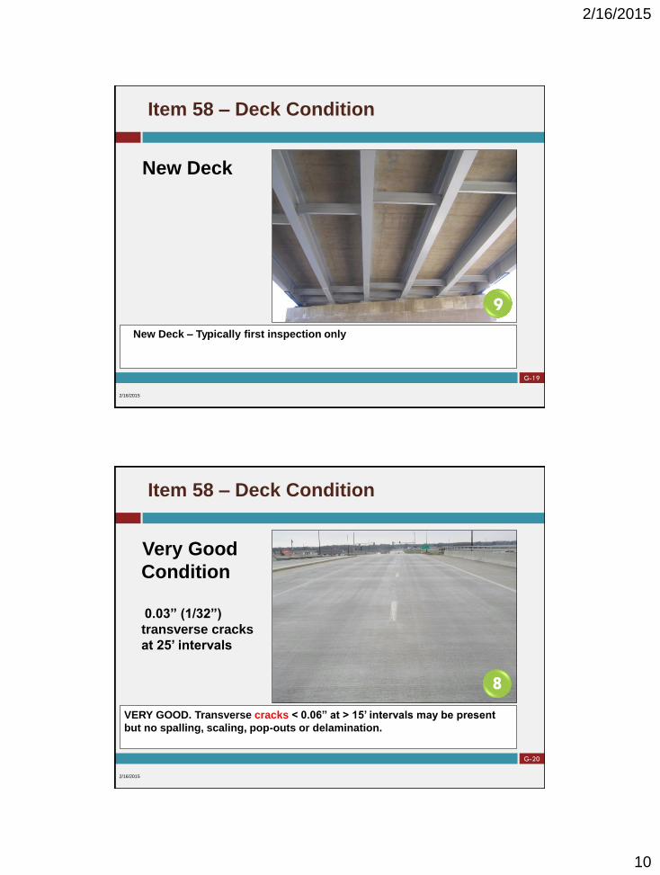
SATISFACTORY. Transverse cracks < 0.06” at < 5’ or > 0.06” at > 5’ intervals over a majority of the
deck, spalls and delaminations may be present on up to 5% of the deck riding surface or soffit
area, up to 10% of the deck soffit may be spalled, delaminated, and map cracked.
2/16/2015
6
Satisfactory
Condition
0.05” transverse
cracks at 3’ intervals
Spalls and
delamination on 4%
of deck surface
G-26
Item 58 – Deck Condition
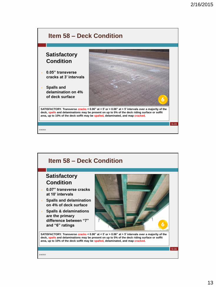
SATISFACTORY. Transverse cracks < 0.06” at < 5’ or > 0.06” at > 5’ intervals over a majority of the
deck, spalls and delaminations may be present on up to 5% of the deck riding surface or soffit
area, up to 10% of the deck soffit may be spalled, delaminated, and map cracked.
2/16/2015
6
Satisfactory
Condition 0.07” transverse cracks
at 10’ intervals
Spalls and delamination
on 4% of deck surface
Spalls & delaminations
are the primary
difference between “7”
and “6” ratings

2/16/2015
14
G-27
Item 58 – Deck Condition
FAIR. Transverse cracks < 0.06” at < 5’ intervals with or without leaching in the majority of the deck,
some longitudinal cracks < 0.06” in the deck, spalls and delaminations may be present on up to 10% of
the deck surface or soffit area, up to 25% of the deck surface or soffit may be spalled, delaminated and
map cracked, up to 10% loss of primary reinforcement in any 6’ bay length.
2/16/2015
5
Fair Condition 0.05” transverse cracks
at 4’ intervals
0.03” longitudinal
cracks present
Spalls and delamination
present on 8% of
concrete deck surface
Do not use condition of
overlay for Deck rating
G-28
Item 58 – Deck Condition
FAIR. Transverse cracks < 0.06” at < 5’ intervals with or without leaching in the majority of the deck,
some longitudinal cracks < 0.06” in the deck, spalls and delaminations may be present on up to 10% of
the deck surface or soffit area, up to 25% of the deck surface or soffit may be spalled, delaminated and
map cracked, up to 10% loss of primary reinforcement in any 6’ bay length.
.
2/16/2015
5
Fair Condition Transverse and longitudinal
cracks < 0.06” present
Minor spalls, delamination,
and map cracking present
on 20% of deck soffit
8% of deck soffit is spalled &
delaminated
Longitudinal cracks are the
primary difference between
“6” and “5” ratings

2/16/2015
15
G-29
Item 58 – Deck Condition
2/16/2015
6 5
Fair: 0.03" transverse cracks at 2'
intervals. 0.05" longitudinal cracks
present with leaching
Satisfactory: 0.03" transverse cracks at 3'
intervals. Minor spalls, delamination, and
map cracking present for less than 10% of
deck
G-30
Item 58 – Deck Condition
POOR. Longitudinal cracks over majority of deck and soffit, spalls and delaminations may be
present on up to 25% of the deck surface or soffit area, up to 50% of the deck surface or soffit
may be spalled, delaminated and map cracked, up to 30% loss of primary reinforcement in any 6’
bay length.
2/16/2015
4
Poor Condition
0.03” transverse cracks
at 3’ intervals
Spalls & delaminations
present on 23% of the
deck surface and
longitudinal cracks over
the majority of the deck

2/16/2015
16
G-31
Item 58 – Deck Condition
POOR. Longitudinal cracks over majority of deck and soffit, spalls and delaminations may be
present on up to 25% of the deck surface or soffit area, up to 50% of the deck surface or soffit
may be spalled, delaminated and map cracked, up to 30% loss of primary reinforcement in any 6’
bay length.
2/16/2015
4
Poor Condition
Spalls, delamination,
and longitudinal
cracks present on 28%
of the deck surface
20% loss of primary
reinforcement in the
outside bay
G-32
Item 58 – Deck Condition
POOR. Longitudinal cracks over majority of deck and soffit, spalls and delaminations may be
present on up to 25% of the deck surface or soffit area, up to 50% of the deck surface or soffit
may be spalled, delaminated and map cracked, up to 30% loss of primary reinforcement in any 6’
bay length.
2/16/2015
4
Poor Condition Transverse and
longitudinal cracks with
leaching are present
Minor spalls,
delamination, and map
cracking present on
40% of deck soffit
22% of deck soffit is
spalled and
delaminated

2/16/2015
17
G-33
Item 58 – Deck Condition
SERIOUS. Condition is similar to the description for a condition rating of “4”, though more
extensive full depth failures are evident to the point that wheel loads may need restricted or
temporary measures implemented.
2/16/2015
3
Serious
Condition
Spalls, delaminations,
and cracks present on
54% of the deck soffit
Bituminous patches
present on 51% of the
deck surface
G-34
Item 58 – Deck Condition
SERIOUS. Condition is similar to the description for a condition rating of “4” , though more
extensive full depth failures are evident to the point that wheel loads may need restricted or
temporary measures implemented.
2/16/2015
3
Serious
Condition
Spalls, delaminations,
and cracking are
present on 53% of the
deck soffit
45% loss of
reinforcement present
in the wheel line

2/16/2015
18
G-35
Item 58 – Deck Condition
CRITICAL. Full depth failures needing patching over much of the deck on a regular basis which
requires special inspections to keep the bridge open, possibly with reduced load limits,
temporary measures may be needed to allow continued use of the structure. The Bureau of
Bridges and Structures shall be notified immediately.
2/16/2015
2
Critical
Condition
3’ long full-depth
deck failure present
Map cracking is
present throughout
the deck
G-36
Item 58 – Deck Condition
CRITICAL. Full depth failures needing patching over much of the deck on a regular basis which
requires special inspections to keep the bridge open, possibly with reduced load limits,
temporary measures may be needed to allow continued use of the structure. The Bureau of
Bridges and Structures shall be notified immediately.
2/16/2015
2
Critical
Condition
4’ long full-depth deck
failure present
Map cracking is
present throughout
the deck

2/16/2015
19
G-37
Item 58 – Deck Condition
2/16/2015
Major Learning Points for Deck Rating:
Document crack size, spacing and orientation
Document area of spalls, delaminations and map
cracking
Document % SL on reinforcement in 6’ typical width
Refer to SIP Manual to select correct rating
G-38
REVIEW
2/16/2015

2/16/2015
1
KD-1
PPC DECK BEAMS
NBI Calibration 2015 2/16/2015
KD-2
Item 59 - PPC Deck Beams
Characteristics of PPC Deck Beams
Effect of overlays type on rating codes
Sounding and scaling beams during inspection
Key Indicators for PPC Deck Beams
Determining Condition Ratings using Key Indicators
Precast Prestressed Concrete Deck Beams
2/16/2015

2/16/2015
2
KD-3
Item 59 - PPC Deck Beams
Introduced in the 1950’s
Advantages over non-
prestressed reinforced
concrete superstructures:
Eliminates need to form,
pour, and cure a deck
Shallow structural depth
Rapid construction
Precast Prestressed Concrete Deck Beams
2/16/2015
KD-4
“Soft” Overlay
Deck (Item 58) and
Superstructure (Item 59)
are rated and coded the
same
Generally consist of
bituminous or oil & chip
overlays
Longitudinal Cracks in
the overlay usually
indicate failed shear
keys
Item 59 - PPC Deck Beams
2/16/2015

2/16/2015
3
KD-5
“Hard” Overlay
Rate the overlay as the
Deck (Item 58) and the
beams as the
Superstructure
(Item 59)
Thickness of Conc.
overlay must be 4” or
greater
Concrete overlay must
be reinforced
Item 59 - PPC Deck Beams
2/16/2015
KD-6
Item 59 - PPC Deck Beams
Sounding • Hammer sounding is
used to detect
delaminated areas
• Delaminated areas will
have a distinctive
“hollow or clacking”
sound when struck
• Sound concrete will
result in a solid
"pinging" sound
• Remove loose &
delaminated concrete
2/16/2015

2/16/2015
4
KD-7
Item 59 - PPC Deck Beams
General Notes:
Prestressing strands,
reinforcement bars or wire
mesh should be considered
exposed in areas where the
concrete appears to be
deteriorated or is unsound
(delaminated condition) to the
level of the strands, bars or
mesh. Patches are
considered delaminated.
2/16/2015
KD-8
Item 59 - PPC Deck Beams
General Notes:
Prestressing strands adjacent
to longitudinal cracks shall
be interpreted as being
exposed.
The dimensions stated on the
following pages relate to the
width of the cross section of
the beams. The “end quarters
of span” do not include the
beam ends (up to 3’).
2/16/2015

2/16/2015
5
KD-9
Item 59 - PPC Deck Beams
Key Indicators
Cracks
Exposed
Reinforcement
Exposed
Strands
Failed Keyway
Code Description
8 VERY GOOD. No notable problems.
7
GOOD. No beams with prestressing strands, stirrup
reinforcement bars or wire mesh exposed. Minor cracking
may be present in keyways, but no leakage occurring
through them, and no differential movement occurring
between deck beams.
6
SATISFACTORY.
Center half of span: No beams with prestressing
strands, stirrup reinforcement or wire mesh bars
exposed, no longitudinal or spalling along the bottom
of the beams.
End quarters of span: No more than 2 strands or 3” of
stirrup reinforcement bars or 3” of wire mesh
exposed in the bottom of any beam.
Larger widths of wire mesh may be exposed due to
inadequate concrete cover occurring during manufacturing
(up to ½” cover), keyway cracking may be evident with
minor leakage, but beams are still fully acting together.
2/16/2015
KD-10
Item 59 - PPC Deck Beams
Key Indicators
Cracks
Exposed
Reinforcement
Exposed
Strands
Failed Keyway
Code Description
5
FAIR.
Center half of span: No more than 2 strands or 3” of
stirrup reinforcement bars or 3” of wire mesh
exposed in any beam, longitudinal cracking or
spalling limited to one edge with no other defects
exposing reinforcement, wire mesh or strands.
End quarters of span: No more than 4 strands or 6” of
stirrup reinforcement bars or 6” of wire mesh
exposed in the bottom of any beam, no more than
one longitudinal crack in any beam without any other
defect.
Beam ends (up to 3’): Prestressed strands, stirrup
reinforcement bars or wire mesh exposed up to full
width of any beam bottom.
Larger widths of wire mesh may be exposed due to
inadequate concrete cover occurring during manufacturing
(up to ½” cover), keyway cracking with extensive leakage
and evidence that beams are beginning to act
independently of each other.
2/16/2015

2/16/2015
6
KD-11
Item 59 - PPC Deck Beams
Key Indicators
Cracks
Exposed
Reinforcement
Exposed
Strands
Failed Keyway
Code Description
4
POOR.
Center half of span: Prestressed strands, stirrup
reinforcement bars or wire mesh exposed for no more
than ⅓ the width of any beam bottom, spalling or
delamination of the top of the beams down to the top
reinforcement, one longitudinal crack in the bottom of
any beam.
End quarters of span: Prestressed strands, stirrup
reinforcement bars or wire mesh exposed for no more
than ½ the width of any beam bottom, two
longitudinal cracks in the bottom of any beam.
Beam ends (up to 3’): Prestressed strands, stirrup
reinforcement bars or wire mesh exposed up to full
width of adjacent beam bottom with no exposed
strands in the second layer of strands and sound
concrete above the bottom layer.
Larger width of wire mesh exposed and actively corroding
due to inadequate concrete cover occurring during
manufacturing (up to ½” cover), keyway has failed with
groups of beams acting independently of others.
2/16/2015
KD-12
Item 59 - PPC Deck Beams
Key Indicators
Cracks
Exposed
Reinforcement
Exposed
Strands
Failed Keyway
Code Description
3
SERIOUS.
Center half of span: Prestressing strands, stirrup
reinforcement bars or wire mesh exposed for no
more that ½ the width of any beam bottom, two
longitudinal cracks in the bottom of any beam,
combinations of deterioration in condition rating “4”.
End quarters of span: Prestressing strands, stirrup
reinforcement bars or wire mesh exposed for no
more than ⅔ the width of any beam bottom,
combination of deterioration in condition rating “4”.
Beam ends (up to 3’): Prestressed strands, stirrup
reinforcement bars or wire mesh exposed full width
of adjacent beam bottom with exposed strands in the
second layer of strands or unsound concrete above
the bottom layer.
Keyways have failed causing 3 or 4 beams to act
independently from others.
2/16/2015

2/16/2015
7
KD-13
Item 59 - PPC Deck Beams
Key Indicators
Cracks
Exposed
Reinforcement
Exposed
Strands
Failed Keyway
Code Description
2
CRITICAL. Similar to but more serious and extensive than
what is described for a condition rating of “3”, transverse
cracks full width in the bottom of the beams, keyways have
failed causing 1 or 2 beams to act independently from
others. Structural elements that are judged to be in critical
condition must receive special inspections in order for the
structure to remain open to traffic. The Bureau of Bridges
and Structures shall be notified immediately.
1
“IMMINENT” FAILURE. Superstructure in “imminent failure”
condition requiring bridge closure or temporary measures to
allow structure to remain open.
0 FAILED. Superstructure that has failed and is beyond repair,
requiring bridge closure.
2/16/2015
KD-14
Item 59 - PPC Deck Beams
If one or more deck beams meets the condition state
requirements for a “4” or below, this condition state
should be applied to the superstructure as a whole.
The condition rating of “4” POOR CONDITION was
selected as this is the level where loss of Structural
Load Capacity generally begins to occur.
When does the condition rating of an individual deck
beam effect that of the whole superstructure if the
other beams are in better condition?
2/16/2015

2/16/2015
8
KD-15
Item 59 - PPC Deck Beams
New Construction
No deficiencies
New Deck Beam – Typically first inspection only
2/16/2015
9
KD-16
Item 59 - PPC Deck Beams
Very Good
Condition
No Deficiencies
Not new
construction
VERY GOOD. No notable problems.
2/16/2015
8

2/16/2015
9
KD-17
Item 59 - PPC Deck Beams
Cracks in the RC
overlay (0.02”)
No noticeable keyway
leakage
Hard overlay would be
rated as the Deck
(Item 58)
Deck would be rated
“4” due to widespread
map cracking.
Item 59 is still a “7”
GOOD. No beams with prestressing strands, stirrup reinforcement bars or wire mesh
exposed. Minor cracking may be present in keyways, but no leakage occurring
through them, and no differential movement occurring between deck beams.
2/16/2015
7
KD-18
Item 59 - PPC Deck Beams
Good Condition
Underside of the
Superstructure in
the previous slide
Reflective
cracking in the
hard overlay
indicated
potential for
keyway cracking
GOOD. No beams with prestressing strands, stirrup reinforcement bars or wire mesh
exposed. Minor cracking may be present in keyways, but no leakage occurring
through them, and no differential movement occurring between deck beams.
7

2/16/2015
10
KD-19
Item 59 - PPC Deck Beams
Satisfactory
Condition
Minor keyway
leakage with
efflorescence
Beams are still
acting together
SATISFACTORY. Center half of span: No beams with prestressing strands, stirrup reinforcement or wire mesh bars exposed, no
longitudinal cracking reinforcement or wire mesh bars exposed, no longitudinal cracking or spalling along the bottom of the
beams. End quarters of span: No more than 2 strands or 3” of stirrup reinforcement bars or 3” of wire mesh exposed in the
bottom of any beam. Larger widths of wire mesh may be exposed due to inadequate concrete cover occurring during
manufacturing (up to ½” cover), keyway cracking may be evident with minor leakage, but beams are still fully acting together.
2/16/2015
6
KD-20
Item 59 - PPC Deck Beams
Satisfactory
Condition
Minor keyway leakage
Beams still acting
together
Inadequate concrete
cover has exposed
mesh on one beam
Verify that exposed
wire is not a strand
SATISFACTORY. Center half of span: No beams with prestressing strands, stirrup reinforcement or wire mesh bars exposed, no
longitudinal cracking reinforcement or wire mesh bars exposed, no longitudinal cracking or spalling along the bottom of the
beams. End quarters of span: No more than 2 strands or 3” of stirrup reinforcement bars or 3” of wire mesh exposed in the
bottom of any beam. Larger widths of wire mesh may be exposed due to inadequate concrete cover occurring during
manufacturing (up to ½” cover), keyway cracking may be evident with minor leakage, but beams are still fully acting together.
2/16/2015
6

2/16/2015
11
KD-21
Item 59 - PPC Deck Beams
Fair Condition
Spall up to 6” wide
in the end quarter
of the span with
reinforcement
exposed
Spall with
reinforcement
exposed near the
beam end
FAIR. Center half of span: No more than 2 strands or 3” of stirrup reinforcement bars or 3” of wire mesh exposed in any beam,
longitudinal cracking or spalling limited to one edge with no other defects exposing reinforcement, wire mesh or strands. End quarters of
span: No more than 4 strands or 6” of stirrup reinforcement bars or 6” of wire mesh exposed in the bottom of any beam, no more than
one longitudinal crack in any beam without any other defect. Beam ends (up to 3’): Prestressed strands, stirrup reinforcement bars or
wire mesh exposed up to full width of any beam bottom. Larger widths of wire mesh may be exposed due to inadequate concrete cover
occurring during manufacturing (up to ½” cover), keyway cracking with extensive leakage and evidence that beams are beginning to act
independently of each other.
2/16/2015
5
KD-22
Item 59 - PPC Deck Beams
Fair Condition
Spall full width on
the beam end with
reinforcement
exposed
No other defects
FAIR. Center half of span: No more than 2 strands or 3” of stirrup reinforcement bars or 3” of wire mesh exposed in any beam,
longitudinal cracking or spalling limited to one edge with no other defects exposing reinforcement, wire mesh or strands. End quarters of
span: No more than 4 strands or 6” of stirrup reinforcement bars or 6” of wire mesh exposed in the bottom of any beam, no more than
one longitudinal crack in any beam without any other defect. Beam ends (up to 3’): Prestressed strands, stirrup reinforcement bars or
wire mesh exposed up to full width of any beam bottom. Larger widths of wire mesh may be exposed due to inadequate concrete cover
occurring during manufacturing (up to ½” cover), keyway cracking with extensive leakage and evidence that beams are beginning to act
independently of each other.
2/16/2015
5

2/16/2015
12
KD-23
Item 59 - PPC Deck Beams
Poor Condition
Spalls with
reinforcement
exposed
Width is 8” of the
36” beam width
(less than 1/3 of the
beam width)
Location of defect
is near mid-span
POOR. Center half of span: Prestressed strands, stirrup reinforcement bars or wire mesh exposed for no more than ⅓ the width of any
beam bottom, spalling or delamination of the top of the beams down to the top reinforcement, one longitudinal crack in the bottom of any
beam. End quarters of span: Prestressed strands, stirrup reinforcement bars or wire mesh exposed for no more than ½ the width of any
beam bottom, two longitudinal cracks in the bottom of any beam. Beam ends (up to 3’): Prestressed strands, stirrup reinforcement bars
or wire mesh exposed up to full width of adjacent beam bottom with no exposed strands in the second layer of strands and sound
concrete above the bottom layer. Larger width of wire mesh exposed and actively corroding due to inadequate concrete cover occurring
during manufacturing (up to ½” cover), keyway has failed with groups of beams acting independently of others.
2/16/2015
4
KD-24
Item 59 - PPC Deck Beams
Poor Condition
Spalls with
reinforcement
exposed
Full width of
adjacent beam
ends
POOR. Center half of span: Prestressed strands, stirrup reinforcement bars or wire mesh exposed for no more than ⅓ the width of any
beam bottom, spalling or delamination of the top of the beams down to the top reinforcement, one longitudinal crack in the bottom of any
beam. End quarters of span: Prestressed strands, stirrup reinforcement bars or wire mesh exposed for no more than ½ the width of any
beam bottom, two longitudinal cracks in the bottom of any beam. Beam ends (up to 3’): Prestressed strands, stirrup reinforcement bars
or wire mesh exposed up to full width of adjacent beam bottom with no exposed strands in the second layer of strands and sound
concrete above the bottom layer. Larger width of wire mesh exposed and actively corroding due to inadequate concrete cover occurring
during manufacturing (up to ½” cover), keyway has failed with groups of beams acting independently of others.
2/16/2015
4

2/16/2015
13
KD-25
Item 59 - PPC Deck Beams
Serious Condition
Spalls or
delaminations
Width is 15” of 36”
beam width
(roughly 1/2 of
width)
Location of defect
is near mid-span
SERIOUS. Center half of span: Prestressing strands, stirrup reinforcement bars or wire mesh exposed for no more that ½ the width of
any beam bottom, two longitudinal cracks in the bottom of any beam, combinations of deterioration in condition rating “4”. End quarters
of span: Prestressing strands, stirrup reinforcement bars or wire mesh exposed for no more than ⅔ the width of any beam bottom,
combination of deterioration in condition rating “4”. Beam ends (up to 3’): Prestressed strands, stirrup reinforcement bars or wire mesh
exposed full width of adjacent beam bottom with exposed strands in the second layer of strands or unsound concrete above the bottom
layer. Keyways have failed causing 3 or 4 beams to act independently from others.
2/16/2015
3
KD-26
Item 59 - PPC Deck Beams
Serious Condition
Spalls or
delaminations
Width is 14” (8” + 6”)
of the 36” beam width
(roughly 1/2 of width)
Located near mid-
span
Keyway failure
SERIOUS. Center half of span: Prestressing strands, stirrup reinforcement bars or wire mesh exposed for no more that ½ the width of
any beam bottom, two longitudinal cracks in the bottom of any beam, combinations of deterioration in condition rating “4”. End quarters
of span: Prestressing strands, stirrup reinforcement bars or wire mesh exposed for no more than ⅔ the width of any beam bottom,
combination of deterioration in condition rating “4”. Beam ends (up to 3’): Prestressed strands, stirrup reinforcement bars or wire mesh
exposed full width of adjacent beam bottom with exposed strands in the second layer of strands or unsound concrete above the bottom
layer. Keyways have failed causing 3 or 4 beams to act independently from others.
2/16/2015
3

2/16/2015
14
KD-27
Item 59 - PPC Deck Beams
Critical Condition
Spalls or
delaminations
Combined width is
26” of the 36” beam
width (over 2/3 of
width)
Several keyways
have failed with
beams acting
independently
CRITICAL. Similar to but more serious and extensive than what is described for a condition rating of “3”,
transverse cracks full width in the bottom of the beams, keyways have failed causing 1 or 2 beams to act
independently from others. Structural elements that are judged to be in critical condition must receive special
inspections in order for the structure to remain open to traffic. The Bureau of Bridges and Structures shall be
notified immediately.
2/16/2015
2
KD-28
Example of beams acting independently
due to keyway failure
Bituminous overlay becomes dislodged
by differential movement of beams
Item 59 - PPC Deck Beams

2/16/2015
15
KD-29
Item 59 - PPC Deck Beams
Critical Condition
Spalls or
delaminations
Width extends 34”
across the 36” beam
width
Exposed strands
visible
Keyway failure
Load Rating
Inspection required
CRITICAL. Similar to but more serious and extensive than what is described for a condition rating of “3”,
transverse cracks full width in the bottom of the beams, keyways have failed causing 1 or 2 beams to act
independently from others. Structural elements that are judged to be in critical condition must receive special
inspections in order for the structure to remain open to traffic. The Bureau of Bridges and Structures shall be
notified immediately.
2/16/2015
2
KD-30
REVIEW

2/16/2015
1
KI-1
PPC I-BEAMS
NBI Calibration 2015 2/16/2015
KI-2
Item 59 – PPC I-Beams
• Used since the 1950’s
• “I” or “Bulb T” shape
• High Strength Concrete
• New sections being
planned for IDOT
Prestressed Concrete I-Beam
2/16/2015
PPC I-Beam PPC Bulb-T

2/16/2015
2
KI-3
Item 59 – PPC I-Beams
• Discuss the “PERIMETER” of
the beam used to define the
beam condition state
• Bottom flange length enclosing
the bottom prestressing strands
Prestressed Concrete I-Beam
2/16/2015
Perimeter
KI-4
Item 59 – PPC I-Beams
2/16/2015
Sounding
• Hammer sounding is
used to detect
delaminated areas
• Delaminated areas
will have a
distinctive “hollow
or clacking” sound
when struck
• Sound concrete will
result in a solid
"pinging" sound

2/16/2015
3
KI-5
Item 59 – PPC I-Beams
2/16/2015
Key Indicators
• Cracks
• Exposed
Reinforcement
• Exposed
Strands
Code Description
8 VERY GOOD. No notable problems.
7
GOOD. No beams with prestressing strands, stirrup
reinforcement bars or wire mesh exposed. Minor shrinkage
or release cracks may be present. Minor map cracking at
drains with sound concrete.
6
SATISFACTORY. Center half of span: No beams with
prestressing strands, stirrup reinforcement exposed.
End quarters of span: No more than 2 strands or 3” of
stirrup reinforcement bars exposed in the bottom of any
beam.
Beam ends (up to 3’): Prestressed strands or stirrup
reinforcement bars exposed up to ½ the perimeter of the
bottom flange of any beam.
Larger width of stirrups may be exposed due to inadequate
concrete cover occurring during manufacturing (up to ½
cover). Webs may be spalled with exposed stirrups and
only surface rust.
KI-6
Item 59 – PPC I-Beams
2/16/2015
Key Indicators
• Cracks
• Exposed
Reinforcement
• Exposed
Strands
Code Description
5
FAIR. Center half of span: Prestressed strands or stirrup
reinforcement bars exposed for no more than 1/4 the
perimeter of the bottom flange of any beam.
End quarters of span: Prestressed strands or stirrup
reinforcement bars exposed for no more than 1/3 the
perimeter of the bottom flange of any beam.
Beam ends (up to 3’): Prestressed strands or stirrup
reinforcement bars exposed from ½ to full perimeter of the
bottom flange of any beam.
Larger areas of stirrup may be exposed due to inadequate
concrete cover that occurs during manufacturing
(up to ½ cover). Webs may be spalled with exposed
stirrups minor section loss.

2/16/2015
4
KI-7
Item 59 – PPC I-Beams
2/16/2015
Key Indicators
• Cracks
• Exposed
Reinforcement
• Exposed
Strands
Code Description
4
POOR. Center half of span: Prestressed strands or stirrup
reinforcement bars exposed for no more than 2/3 the
perimeter of the bottom flange of any beam.
End quarters of span: Prestressed strands or stirrup
reinforcement bars exposed up to full perimeter of the
bottom flange of any beam. No strands are exposed inside
the exterior perimeter of strands.
Beam ends (up to 3’): Prestressed strands or stirrup
reinforcement bars exposed full perimeter of the bottom
flange of any beam with some strands exposed inside the
exterior perimeter of strands.
Webs are spalled with exposed stirrups with up to 30%
section loss at ends of beams.
KI-8
Item 59 – PPC I-Beams
2/16/2015
Key Indicators
• Cracks
• Exposed
Reinforcement
• Exposed
Strands
Code Description
3
SERIOUS. Center half of span: Prestressed strands or
stirrup reinforcement bars exposed up to full perimeter of
the bottom flange of any beam. No strands
are exposed inside the exterior perimeter of strands.
End quarters of span: Prestressing strands, stirrup
reinforcement bars exposed for the full perimeter of the
bottom flange of any beam with some strands exposed
inside the exterior perimeter of strands.
Hairline transverse cracks in bottom of beams or hairline
vertical/diagonal shear cracks in beam webs may be
developing.

2/16/2015
5
KI-9
Item 59 – PPC I-Beams
2/16/2015
Key Indicators
• Cracks
• Exposed
Reinforcement
• Exposed
Strands
Code Description
2
CRITICAL. Similar to but more serious and extensive than
what is described for a condition rating of “3”. Structural
elements that are judged to be in critical condition must
receive special inspections in order for the structure to
remain open to traffic. Measurable shear or transverse
cracks. The Bureau of Bridges and Structures shall be
notified immediately.
KI-10
Item 59 – PPC I-Beams
New
Construction
• No defects
• First
inspection
New PPC I-Beam – Typically first inspection only
2/16/2015
9

2/16/2015
6
KI-11
Item 59 – PPC I-Beams
Very Good
• No
deficiencies
• Second
inspection
VERY GOOD. No notable problems.
2/16/2015
8
KI-12
Item 59 – PPC I-Beams
Good
Minor
shrinkage
cracks present
in beams
GOOD. No beams with prestressing strands, stirrup reinforcement bars or wire mesh exposed.
Minor shrinkage or release cracks may be present. Minor map cracking at drains with sound
concrete.
2/16/2015
7
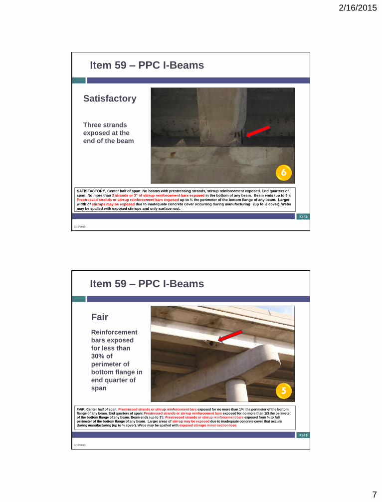
2/16/2015
7
KI-13
Item 59 – PPC I-Beams
Satisfactory
Three strands
exposed at the
end of the beam
SATISFACTORY. Center half of span: No beams with prestressing strands, stirrup reinforcement exposed. End quarters of
span: No more than 2 strands or 3” of stirrup reinforcement bars exposed in the bottom of any beam. Beam ends (up to 3’):
Prestressed strands or stirrup reinforcement bars exposed up to ½ the perimeter of the bottom flange of any beam. Larger
width of stirrups may be exposed due to inadequate concrete cover occurring during manufacturing (up to ½ cover). Webs
may be spalled with exposed stirrups and only surface rust.
2/16/2015
6
KI-15
Item 59 – PPC I-Beams
Fair
Reinforcement
bars exposed
for less than
30% of
perimeter of
bottom flange in
end quarter of
span
FAIR. Center half of span: Prestressed strands or stirrup reinforcement bars exposed for no more than 1/4 the perimeter of the bottom
flange of any beam. End quarters of span: Prestressed strands or stirrup reinforcement bars exposed for no more than 1/3 the perimeter
of the bottom flange of any beam. Beam ends (up to 3’): Prestressed strands or stirrup reinforcement bars exposed from ½ to full
perimeter of the bottom flange of any beam. Larger areas of stirrup may be exposed due to inadequate concrete cover that occurs
during manufacturing (up to ½ cover). Webs may be spalled with exposed stirrups minor section loss.
2/16/2015
5

2/16/2015
8
KI-16
Item 59 – PPC I-Beams
No beams with reinforcement
exposed at center span
Spall with 4 exposed strands in the
end quarter
2/16/2015
5 6
KI-17
Item 59 – PPC I-Beams
Poor
Reinforcement
bars exposed
for more than
55% of
perimeter of
bottom flange
POOR. Center half of span: Prestressed strands or stirrup reinforcement bars exposed for no more than 2/3 the perimeter of
the bottom flange of any beam. End quarters of span: Prestressed strands or stirrup reinforcement bars exposed up to full
perimeter of the bottom flange of any beam. No strands are exposed inside the exterior perimeter of strands. Beam ends (up
to 3’): Prestressed strands or stirrup reinforcement bars exposed full perimeter of the bottom flange of any beam with some
strands exposed inside the exterior perimeter of strands. Webs are spalled with exposed stirrups with up to 30% section
loss at ends of beams.
2/16/2015
4

2/16/2015
9
KI-18
Item 59 – PPC I-Beams
Serious
Strands exposed
for full perimeter
of bottom flange in
center half of span
SERIOUS. Center half of span: Prestressed strands or stirrup reinforcement bars exposed up to full perimeter of the bottom
flange of any beam. No strands are exposed inside the exterior perimeter of strands. End quarters of span: Prestressing
strands, stirrup reinforcement bars exposed for the full perimeter of the bottom flange of any beam with some strands
exposed inside the exterior perimeter of strands. Hairline transverse cracks in bottom of beams or hairline vertical/diagonal
shear cracks in beam webs may be developing
2/16/2015
3
KI-19
Item 59 – PPC I-Beams
Critical
• Exterior beam
has failed
• Strands exposed
for full perimeter
of bottom flange
at center span
CRITICAL. Similar to but more serious and extensive than what is described for a condition rating
of “3”. Structural elements that are judged to be in critical condition must receive special
inspections in order for the structure to remain open to traffic. Measurable shear or transverse
cracks.
2/16/2015
2

2/16/2015
10
KI-20
REVIEW

2/16/2015
1
CULVERTS
NBI Calibration 2015 2/16/2015
N-2
Item 62 - Culverts
Types of Culverts
Related Inventory Items
Requirements for Concrete Coring
Condition Ratings
2/16/2015

2/16/2015
2
N-3
Item 62 - Culverts
2/16/2015
Types of Culverts
Concrete Box Culverts
Single or Multiple Cell
CIP or Precast Concrete
Precast Concrete Pipe Culverts
Round
Elliptical
Corrugated Metal Pipe Culverts
Round or Elliptical
Large Arches
N-4
Item 62 - Culverts
Related Inventory Items
Guardrail over Culverts
Not Bridge Railing (Item 36A)
Items 36E/F – Guardrails on
Structure Type (Right/Left)
Usually coded “1” for Steel Plate
Beam Guardrail
Structure Length (Item 48)
Measured along centerline of
roadway, not at right angle to culvert
Length along roadway is equal to
the right-angle dimension divided by
the cosine of the skew angle.
2/16/2015

2/16/2015
3
N-5
Item 62 - Culverts
Related Inventory Items Item 62A – Culvert Cells (Count)
Item 62B – Culvert Cell Width (Ft.) Horizontal width, measured at right angle to culvert, of
individual cells or openings in the culvert
Item 62C – Culvert Cell Height Vertical height of individual cells or openings in the culvert
If more than one height exist, record the predominate height
Item 62D – Culvert Opening Area Total cross section area of all cells of the culvert
Areas of dissimilar individual cells, report the true
calculated square footage of opening.
Measurement does not have to agree with the calculation
made from values reported in Items 62B and 62C
Variable opening dimensions should be recorded in
Item 8A1 – Bridge Remarks (General)
Item 62E – Culvert Fill Depth The depth of fill (earth and pavement thickness) measured
from the top of the culvert structure to the top of the
pavement surface
2/16/2015
N-6
Item 62 - Culverts
2/16/2015
Key Indicators
Cracks
Scaling
Spalls/Delams
Section Loss
Code Description
N NOT APPLICABLE. Use when structure is not a culvert.
9 EXCELLENT. No deficiencies
8 VERY GOOD. No noticeable or noteworthy deficiencies
which affect the condition of the culvert, insignificant scrape
marks caused by drift.
7
GOOD. Non structural cracks at > 10’ spacing, light scaling,
and insignificant spalling which does not expose reinforcing
steel, metal culverts have a smooth symmetrical curvature
with superficial corrosion and no pitting, insignificant
damage caused by drift with no misalignment and not
requiring corrective action, some minor scour has occurred
near curtain walls, wingwalls, or pipes.

2/16/2015
4
N-7
Item 62 - Culverts
2/16/2015
Key Indicators
Cracks
Scaling
Spalls/Delams
Section Loss
Code Description
6
SATISFACTORY. Non-structural cracking with some leaching
at >5’ spacing over the majority of the top slab, spalls and
delaminations may be present on up to 5% of the concrete or
masonry walls or slabs exposing primary reinforcement with
surface rust only, up to 10% of the surface area of walls and
slabs may be map cracked, spalled and delaminated, metal
culverts have a smooth curvature, non-symmetrical shape,
minor corrosion or measurable pitting, local minor scour at
curtain walls, wingwalls, or pipes
5
FAIR. Non-structural cracking with leaching at < 5’ intervals
over the majority of the slab or wall surfaces, isolated
structural cracks < 0.03“ in walls or slabs, spalls and
delaminations on the bottom concrete slabs with up to 10%
loss of primary reinforcement over a 6’ width, spalls on
concrete walls with up to 10% loss of concrete or
reinforcement area, up to 10% of the top surface area of the
top slab may be spalled and delaminated, metal culverts
have significant distortion and deflection in no more than one
section, or significant corrosion or deep pitting, up to 10%
average section loss, up to ½ the wall thickness in one
section, minor settlement or misalignment, noticeable scour
or erosion at curtain walls, wingwalls, or pipes without
undermining.
N-8
Item 62 - Culverts
2/16/2015
Key Indicators
Cracks
Scaling
Spalls/Delams
Section Loss
Code Description
4
POOR. Structural cracks in top slab up to 0.06”, structural
cracks in walls up to 0.125”, section loss of primary
reinforcement up to 30%, up to 25% of compression surface
area spalled or delaminated on slabs and walls(tension
areas may be totally spalled), metal culverts have
significant distortion and deflection on more than one
section, extensive corrosion or deep pitting throughout up
to 30% section loss on average, considerable settlement or
misalignment, considerable scour or erosion at curtain
walls, wingwalls or pipes with undermining.
3
SERIOUS. Any worse or combined condition described in
condition rating "4”, up to 50% loss, metal culverts have
extreme distortion and deflection in one section (collapse),
extensive corrosion, or deep pitting with scattered
perforations, severe movement or differential settlement of
the segments, or loss of fill. Holes may exist in walls or
slabs. Integral wingwalls nearly severed from culvert.
Severe undermining of curtain walls, wingwalls or pipes.

2/16/2015
5
N-9
Item 62 - Culverts
2/16/2015
Key Indicators
Cracks
Scaling
Spalls/Delams
Section Loss
Code Description
2
CRITICAL. Large areas of slab or walls spalled full depth
near traffic, large area of reinforcement losses greater than
50% near traffic, metal culverts have extreme distortion and
deflection throughout with extensive perforations due to
corrosion, integral wingwalls collapsed, severe settlement of
roadway due to loss of fill, section of culvert may have failed
and can no longer support embankment, complete
undermining of curtain walls and pipes, special feature
inspection will be required to keep the structure open with
possible load restrictions. The Bureau of Bridges and
Structures shall be notified immediately.
1 IMMINENT FAILURE. Bridge closed. Corrective action may
return bridge to light service.
0 FAILED. Bridge closed. Replacement necessary.
N-10
Item 62 - Culverts
Requirements for
Concrete Coring
IDOT BLRS-CL 2008-16: Inspection
and Coring of Reinforced Concrete
Structures
Concrete cores may be required for
Reinforced Concrete Box Culverts
having Culvert (Item 62) condition
ratings of “4” or less.
The cores are needed in order to
make an accurate determination of
remaining load-carrying capacity.
2/16/2015

2/16/2015
6
N-11
Item 62 - Culverts
EXCELLENT. No deficiencies – Typically first inspection only
2/16/2015
9
New
Construction
No Deficiencies
N-12
Item 62 - Culverts
VERY GOOD. No noticeable or noteworthy deficiencies which affect the
condition of the culvert, insignificant scrape marks caused by drift.
2/16/2015
8
Very Good
Condition
No significant
defects

2/16/2015
7
N-13
Item 62 - Culverts
GOOD. Non structural cracks at > 10’ spacing, light scaling, and insignificant spalling which does
not expose reinforcing steel, metal culverts have a smooth symmetrical curvature with superficial
corrosion and no pitting, insignificant damage caused by drift with no misalignment and not
requiring corrective action, some minor scour has occurred near curtain walls, wingwalls, or
pipes.
2/16/2015
7
Good Condition
Minor scaling
Insignificant
spalling
No exposed
reinforcement
N-14
Item 62 - Culverts
GOOD. Non structural cracks at > 10’ spacing, light scaling, and insignificant spalling which does
not expose reinforcing steel, metal culverts have a smooth symmetrical curvature with superficial
corrosion and no pitting, insignificant damage caused by drift with no misalignment and not
requiring corrective action, some minor scour has occurred near curtain walls, wingwalls, or
pipes.
2/16/2015
7
Good Condition
Hairline vertical
cracks in center wall
Crack spacing
greater than 10’
Light scaling
present

2/16/2015
8
N-15
Item 62 - Culverts
SATISFACTORY. Non-structural cracking with some leaching at >5’ spacing over the majority of the top
slab, spalls and delaminations may be present on up to 5% of the concrete or masonry walls or slabs
exposing primary reinforcement with surface rust only, up to 10% of the surface area of walls and slabs
may be map cracked, spalled and delaminated, metal culverts have a smooth curvature, non-
symmetrical shape, minor corrosion or measurable pitting, local minor scour at curtain walls, wingwalls,
or pipes
2/16/2015
6
Satisfactory
Condition Vertical cracks in the
walls with leaching
10’ crack spacing
Minor spalls and
delaminations
present on 5% of
surface
N-16
Item 62 - Culverts
SATISFACTORY. Non-structural cracking with some leaching at >5’ spacing over the majority of the top
slab, spalls and delaminations may be present on up to 5% of the concrete or masonry walls or slabs
exposing primary reinforcement with surface rust only, up to 10% of the surface area of walls and slabs
may be map cracked, spalled and delaminated, metal culverts have a smooth curvature, non-
symmetrical shape, minor corrosion or measurable pitting, local minor scour at curtain walls, wingwalls,
or pipes
2/16/2015
6
Satisfactory
Condition
Cracks with leaching
at 10’ spacing
Minor spalls and
delaminations
present on 3% of
surface

2/16/2015
9
N-17
Item 62 - Culverts
2/16/2015
5
FAIR. Non-structural cracking with leaching at < 5’ intervals over the majority of the slab or wall surfaces, isolated
structural cracks < 0.03“ in walls or slabs, spalls and delaminations on the bottom concrete slabs with up to 10%
loss of primary reinforcement over a 6’ width, spalls on concrete walls with up to 10% loss of concrete or
reinforcement area, up to 10% of the top surface area of the top slab may be spalled and delaminated, metal
culverts have significant distortion and deflection in no more than one section, or significant corrosion or deep
pitting, up to 10% average section loss, up to ½ the wall thickness in one section, minor settlement or
misalignment, noticeable scour or erosion at curtain walls, wingwalls, or pipes without undermining.
Fair Condition
Leaching map cracks
throughout the top
slab soffit
Several small
delaminations
throughout
N-18
Item 62 - Culverts
FAIR. Non-structural cracking with leaching at < 5’ intervals over the majority of the slab or wall surfaces, isolated
structural cracks < 0.03“ in walls or slabs, spalls and delaminations on the bottom concrete slabs with up to 10%
loss of primary reinforcement over a 6’ width, spalls on concrete walls with up to 10% loss of concrete or
reinforcement area, up to 10% of the top surface area of the top slab may be spalled and delaminated, metal
culverts have significant distortion and deflection in no more than one section, or significant corrosion or deep
pitting, up to 10% average section loss, up to ½ the wall thickness in one section, minor settlement or
misalignment, noticeable scour or erosion at curtain walls, wingwalls, or pipes without undermining.
2/16/2015
5
Fair Condition
Scour present on the
downstream end
Cutoff wall exposed,
but not undermined
Minor spalling of the
headwall

2/16/2015
10
N-19
Item 62 - Culverts
2/16/2015
5
FAIR. Non-structural cracking with leaching at < 5’ intervals over the majority of the slab or wall surfaces, isolated
structural cracks < 0.03“ in walls or slabs, spalls and delaminations on the bottom concrete slabs with up to 10%
loss of primary reinforcement over a 6’ width, spalls on concrete walls with up to 10% loss of concrete or
reinforcement area, up to 10% of the top surface area of the top slab may be spalled and delaminated, metal
culverts have significant distortion and deflection in no more than one section, or significant corrosion or deep
pitting, up to 10% average section loss, up to ½ the wall thickness in one section, minor settlement or
misalignment, noticeable scour or erosion at curtain walls, wingwalls, or pipes without undermining.
Fair Condition
10% section loss
along the bottom and
near the water line
Slight distortion under
the roadway
N-20
Item 62 - Culverts
POOR. Structural cracks in top slab up to 0.06”, structural cracks in walls up to 0.125”, section loss of
primary reinforcement up to 30%, up to 25% of compression surface area spalled or delaminated on
slabs and walls(tension areas may be totally spalled), metal culverts have significant distortion and
deflection on more than one section, extensive corrosion or deep pitting throughout up to 30% section
loss on average, considerable settlement or misalignment, considerable scour or erosion at curtain
walls, wingwalls or pipes with undermining.
2/16/2015
4
Poor Condition Leaching map cracks
present in top slab
Cracks up to 0.06” in top
slab
Leaching vertical cracks
in walls up to 0.125”
Concrete cores may be
needed

2/16/2015
11
N-21
Item 62 - Culverts
Structural cracks up to 0.06” in
top slab.
Structural cracks up to 0.125” in
walls.
Isolated structural cracks less
than 0.03" in walls or slabs.
Spalls and delaminations on the
bottom concrete slabs.
2/16/2015
4 5
N-22
Item 62 - Culverts
SERIOUS. Any worse or combined condition described in condition rating "4”, up to 50% loss,
metal culverts have extreme distortion and deflection in one section (collapse), extensive
corrosion, or deep pitting with scattered perforations, severe movement or differential settlement
of the segments, or loss of fill. Holes may exist in walls or slabs. Integral wingwalls nearly
severed from culvert. Severe undermining of curtain walls, wingwalls or pipes.
2/16/2015
3
Serious Condition Large spalls present
with exposed primary
reinforcement
35% section loss in
primary reinforcement
Top slab soffit is
delaminated and
slightly sagging

2/16/2015
12
N-23
Item 62 - Culverts
SERIOUS. Any worse or combined condition described in condition rating "4”, up to 50% loss,
metal culverts have extreme distortion and deflection in one section (collapse), extensive
corrosion, or deep pitting with scattered perforations, severe movement or differential settlement
of the segments, or loss of fill. Holes may exist in walls or slabs. Integral wingwalls nearly
severed from culvert. Severe undermining of curtain walls, wingwalls or pipes.
2/16/2015
3
Serious Condition
Bottom slab is
undermined and
collapsing
Center wall is settling
Top slab is separating
at center wall
N-24
Item 62 - Culverts
SERIOUS. Any worse or combined condition described in condition rating "4”, up to 50% loss,
metal culverts have extreme distortion and deflection in one section (collapse), extensive
corrosion, or deep pitting with scattered perforations, severe movement or differential settlement
of the segments, or loss of fill. Holes may exist in walls or slabs. Integral wingwalls nearly
severed from culvert. Severe undermining of curtain walls, wingwalls or pipes.
2/16/2015
3
Serious Condition Distortion in two
sections
Separation of sections
has occurred
Loss of fill has
occurred at separation
between sections

2/16/2015
13
N-25
Item 62 - Culverts
SERIOUS. Any worse or combined condition described in condition rating "4”, up to 50% loss,
metal culverts have extreme distortion and deflection in one section (collapse), extensive
corrosion, or deep pitting with scattered perforations, severe movement or differential settlement
of the segments, or loss of fill. Holes may exist in walls or slabs. Integral wingwalls nearly
severed from culvert. Severe undermining of curtain walls, wingwalls or pipes.
2/16/2015
3
Serious Condition
45% section loss
along water line
Several holes through
the walls near ends of
culvert
N-26
Item 62 - Culverts
CRITICAL. Large areas of slab or walls spalled full depth near traffic, large area of reinforcement losses greater
than 50% near traffic, metal culverts have extreme distortion and deflection throughout with extensive
perforations due to corrosion, integral wingwalls collapsed, severe settlement of roadway due to loss of fill,
section of culvert may have failed and can no longer support embankment, complete undermining of curtain walls
and pipes, special inspection will be required to keep the structure open with possible load restrictions. The
Bureau of Bridges and Structures shall be notified immediately.
2/16/2015
2
Critical Condition Large spall under traffic
lane with two layers of
reinforcement exposed
There is movement in
the remaining slab
under live load
Notify Bureau of Bridges
and Structures
immediately!

2/16/2015
14
N-27
Item 62 - Culverts
CRITICAL. Large areas of slab or walls spalled full depth near traffic, large area of reinforcement losses greater
than 50% near traffic, metal culverts have extreme distortion and deflection throughout with extensive
perforations due to corrosion, integral wingwalls collapsed, severe settlement of roadway due to loss of fill,
section of culvert may have failed and can no longer support embankment, complete undermining of curtain walls
and pipes, special inspection will be required to keep the structure open with possible load restrictions. The
Bureau of Bridges and Structures shall be notified immediately.
2/16/2015
2
Critical Condition
The bottom of the east
pipe has failed
Settlement of
approximately 3’ has
occurred
Settlement has caused
a dip in the roadway
REVIEW

2/16/2015
1
CONCLUSION – DAY 1
NBI Calibration 2015 2/16/2015 T1-2
Conclusion – Day 1
Questions?
or
Comments
T1-3
Conclusion – Day 1
Class resumes tomorrow morning at 8:00 am
Keep your Response Card, Lanyard, and Name
Card together
Leave your Response Card with us, make sure
your Name Card is visible to facilitate
redistribution of the Cards tomorrow morning.
T1-4
Conclusion – Day 1
Don’t forget to return your
Response Cards and Lanyards