Introduction: Analysis of Electronic Circuits - KU...
42
1/20/2012 Introduction 1/2 Jim Stiles The Univ. of Kansas Dept. of EECS Introduction: Analysis of Electronic Circuits Reading Assignment: KVL and KCL text from EECS 211 Just like EECS 211, the majority of problems (hw and exam) in EECS 312 will be circuit analysis problems. Thus, a key to doing well in 312 is to thoroughly know the material from 211!! So, before we get started with 312, let’s review 211 and see how it applies to electronic circuits. A: Even if you did extremely well in 211, you will want to pay attention to this review. You will see that the concepts of 211 are applied a little differently when we analyze electronic circuits. Both the conventions and the approach used for analyzing electronic circuits will perhaps be unfamiliar to you at first— I thus imagine that everyone (I hope) will find this review to be helpful. Q: I aced EECS 211 last semester; can I just skip this “review”??
Transcript of Introduction: Analysis of Electronic Circuits - KU...
1/20/2012 Introduction 1/2
Jim Stiles The Univ. of Kansas Dept. of EECS
Introduction: Analysis of Electronic Circuits
Reading Assignment: KVL and KCL text from EECS 211 Just like EECS 211, the majority of problems (hw and exam) in EECS 312 will be circuit analysis problems. Thus, a key to doing well in 312 is to thoroughly know the material from 211!! So, before we get started with 312, let’s review 211 and see how it applies to electronic circuits. A: Even if you did extremely well in 211, you will want to pay attention to this review. You will see that the concepts of 211 are applied a little differently when we analyze electronic circuits. Both the conventions and the approach used for analyzing electronic circuits will perhaps be unfamiliar to you at first—I thus imagine that everyone (I hope) will find this review to be helpful.
Q: I aced EECS 211 last semester; can I just skip this “review”??

1/20/2012 Introduction 2/2
Jim Stiles The Univ. of Kansas Dept. of EECS
ELECTRONIC CIRCUIT NOTATION KVL AND ELECTRONIC CIRCUIT NOTATION ANALYSIS OF ELECTRONIC CIRCUITS Even the quantities of current and resistance are a little different for electronic circuits! A: Not exactly! VOLTS, MILLI-AMPS, KILO-OHMS Now let’s try an example! EXAMPLE: CIRCUIT ANALYSIS USING ELECTRONIC CIRCUIT NOTATION
Q: You mean we don’t use Amperes and Ohms??
1/20/2012 Electronic Circuit Notation present 1/12
Jim Stiles The Univ. of Kansas Dept. of EECS
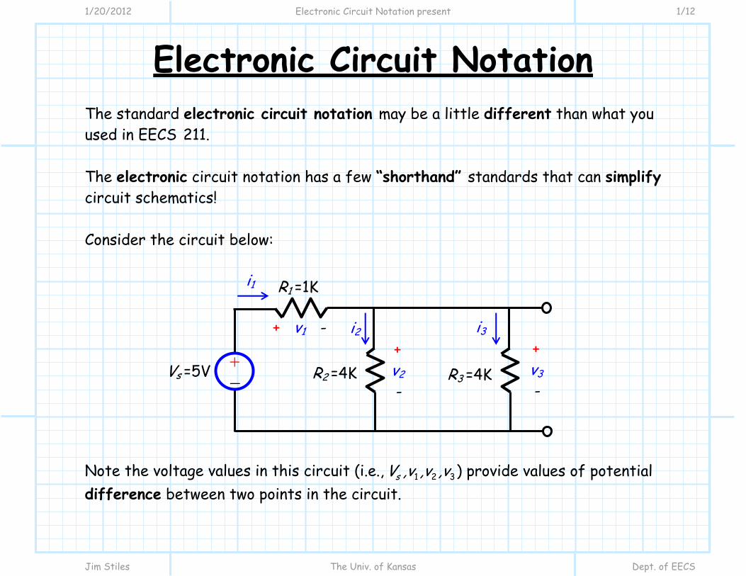
Electronic Circuit Notation The standard electronic circuit notation may be a little different than what you used in EECS 211. The electronic circuit notation has a few “shorthand” standards that can simplify circuit schematics! Consider the circuit below: Note the voltage values in this circuit (i.e., 1 2 3sV ,v ,v ,v ) provide values of potential difference between two points in the circuit.
R1 =1K
Vs =5V +-
R2 =4K R3 =4K
+ v1 -
i1
i2 i3 + v2 -
+ v3 -
1/20/2012 Electronic Circuit Notation present 2/12
Jim Stiles The Univ. of Kansas Dept. of EECS
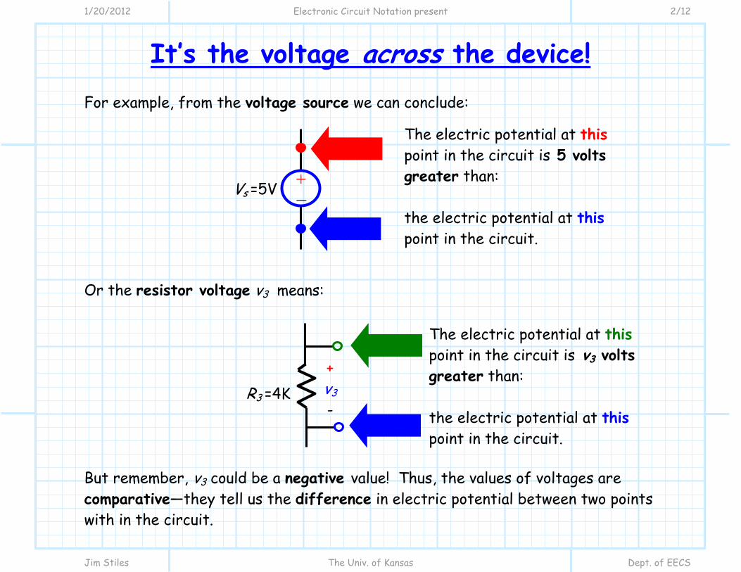
It’s the voltage across the device! For example, from the voltage source we can conclude: Or the resistor voltage v3 means: But remember, v3 could be a negative value! Thus, the values of voltages are comparative—they tell us the difference in electric potential between two points with in the circuit.
The electric potential at this point in the circuit is 5 volts greater than: the electric potential at this point in the circuit.
Vs =5V +-
The electric potential at this point in the circuit is v3 volts greater than: the electric potential at this point in the circuit.
+ v3 -
R3 =4K
1/20/2012 Electronic Circuit Notation present 3/12
Jim Stiles The Univ. of Kansas Dept. of EECS
KVL of tall buildings
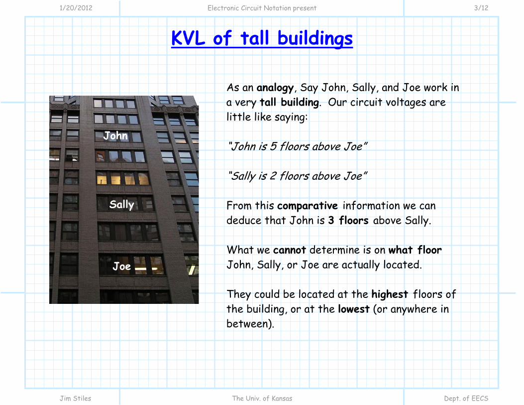
As an analogy, Say John, Sally, and Joe work in a very tall building. Our circuit voltages are little like saying: “John is 5 floors above Joe” “Sally is 2 floors above Joe” From this comparative information we can deduce that John is 3 floors above Sally. What we cannot determine is on what floor John, Sally, or Joe are actually located. They could be located at the highest floors of the building, or at the lowest (or anywhere in between).
Joe
Sally
John
1/20/2012 Electronic Circuit Notation present 4/12
Jim Stiles The Univ. of Kansas Dept. of EECS
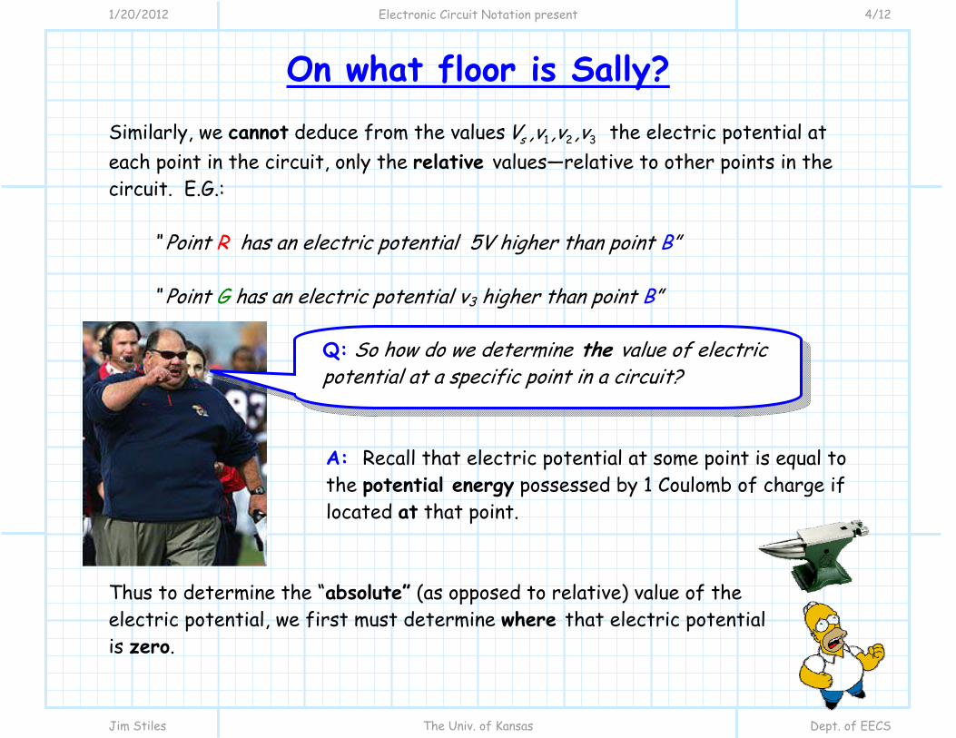
On what floor is Sally? Similarly, we cannot deduce from the values 1 2 3sV ,v ,v ,v the electric potential at each point in the circuit, only the relative values—relative to other points in the circuit. E.G.:
“ Point R has an electric potential 5V higher than point B” “ Point G has an electric potential v3 higher than point B”
A: Recall that electric potential at some point is equal to the potential energy possessed by 1 Coulomb of charge if located at that point.
Thus to determine the “absolute” (as opposed to relative) value of the electric potential, we first must determine where that electric potential is zero.
Q: So how do we determine the value of electric potential at a specific point in a circuit?
1/20/2012 Electronic Circuit Notation present 5/12
Jim Stiles The Univ. of Kansas Dept. of EECS
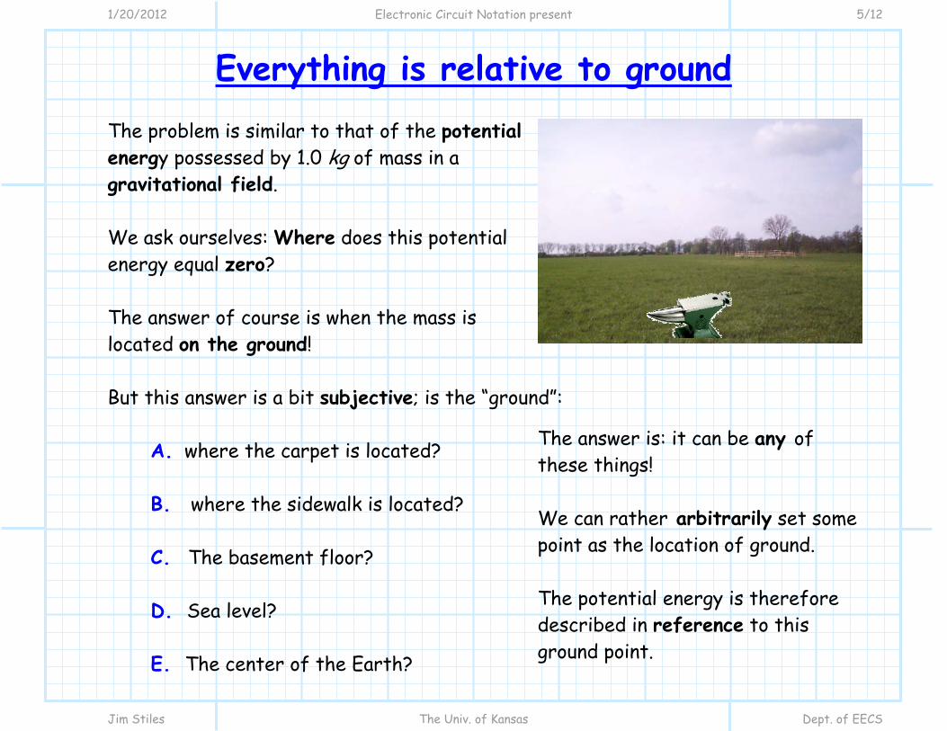
Everything is relative to ground The problem is similar to that of the potential energy possessed by 1.0 kg of mass in a gravitational field. We ask ourselves: Where does this potential energy equal zero? The answer of course is when the mass is located on the ground! But this answer is a bit subjective; is the “ground”:
A. where the carpet is located? B. where the sidewalk is located? C. The basement floor? D. Sea level? E. The center of the Earth?
The answer is: it can be any of these things! We can rather arbitrarily set some point as the location of ground. The potential energy is therefore described in reference to this ground point.

1/20/2012 Electronic Circuit Notation present 6/12
Jim Stiles The Univ. of Kansas Dept. of EECS
We can now determine where they are—with respect to ground
For tall buildings, the ground floor is usually defined as the floor containing the front door. Now, having defined a ground reference, if we add to our earlier statements:
“Joe is 32 floors above ground”
We can deduce: “ John is 5 floors above Joe—therefore John is on the 37th floor” “ Sally is 2 floors above Joe—therefore Sally is on the 34th floor”
Joe
Sally
John

1/20/2012 Electronic Circuit Notation present 7/12
Jim Stiles The Univ. of Kansas Dept. of EECS
Answer his question, or he will force you to do push-ups
A: Absolutely! We just pick a point on the circuit and call it the ground potential. We can then reference the electric potential at every point in the circuit with respect to this ground potential!
Q: So, can we define a ground potential for our circuit?

1/20/2012 Electronic Circuit Notation present 8/12
Jim Stiles The Univ. of Kansas Dept. of EECS
Ground Potential
Consider now the circuit: Note we have added an “upside-down triangle” to the circuit—this denotes the location we define as our ground potential! Now, if we add the statement:
“Point B is at an electric potential of zero volts (with respect to ground).” We can conclude:
“Point R is at an electric potential of 5 Volts (with respect to ground).”
“Point G is at an electric potential of v3 Volts (with respect to ground).”
R1 =1K
Vs =5V +-
R2 =4K R3 =4K
+ v1 -
i1
i2 i3 + v2 -
Look at this!
+ v3 -

1/20/2012 Electronic Circuit Notation present 9/12
Jim Stiles The Univ. of Kansas Dept. of EECS
All grounds are connected Note that all the points within the circuit that reside at ground potential form a rather large node: Standard electronic notation simplifies the schematic by placing the ground symbol at each device terminal: Note that all terminals connected to ground are likewise connected to each other!
R1 =1K
Vs =5V +-
R2 =4K R3 =4K
+ v1 -
i1
i2 i3 + v2 -
+ v3 -
R1 =1K
Vs=5 V
+-
R2 =4K R3 =4K
+ v1 -
i1
i2 i3 + v2 -
Look at this!
+ v3 -

1/20/2012 Electronic Circuit Notation present 10/12
Jim Stiles The Univ. of Kansas Dept. of EECS
We need not know the particulars Now, in the case where one terminal of a device is connected to ground potential, the electric potential (with respect to ground) of the other terminal is easily determined: For this example, it is apparent that the voltage source simply enforces the condition that the + terminal is at 5.0 Volts with respect to ground. Thus, we often simplify our electronic circuit schematics as:
The electric potential at this point in the circuit is 5 volts greater than ground (i.e., 5 volts). This point is at ground potential (i.e., zero volts).
Vs =5V +-
R1 =1K 5.0V
R2 =4K R3 =4K
+ v1 -
i1
i2 i3 + v2 -
+ v3 -

1/20/2012 Electronic Circuit Notation present 11/12
Jim Stiles The Univ. of Kansas Dept. of EECS
We can express the voltage at each node—with respect to ground
Finally, we find that: Thus, we can simplify our circuit further as:
The electric potential at this point in the circuit is v2 volts greater than ground potential (i.e., v3 ). This point is at ground potential (i.e. zero volts).
+ v3 -
R3 =4K
R1 =1K 5.0V
R2 =4K R3 =4K
+ v1 -
i1
i2 i3 + v2 -
v3
1/20/2012 Electronic Circuit Notation present 12/12
Jim Stiles The Univ. of Kansas Dept. of EECS
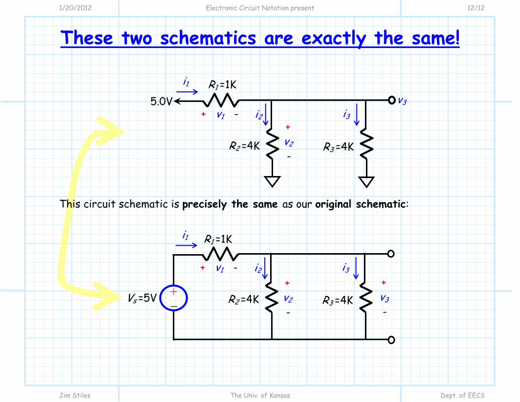
These two schematics are exactly the same! This circuit schematic is precisely the same as our original schematic:
R1 =1K
Vs =5V +-
R2 =4K R3 =4K
+ v1 -
i1
i2 i3 + v2 -
+ v3 -
R1 =1K 5.0V
R2 =4K R3 =4K
+ v1 -
i1
i2 i3 + v2 -
v3

1/20/2012 KVL and Electronic Notation present 1/16
Jim Stiles The Univ. of Kansas Dept. of EECS
KVL and Electronic Circuit Notation
Consider this circuit:
We can apply Kirchoff’s Voltage Law (KVL) to relate the voltages in this circuit in any number of ways.
R1 =3K
R2 =2K
R3 =1K
- v4 +
i
+ vR3 -
Vs2 =4V + -
Vs1 =2V + -
- v5 +
+ vR2 -
+ vR1 -
1/20/2012 KVL and Electronic Notation present 2/16
Jim Stiles The Univ. of Kansas Dept. of EECS
Two equally valid equations
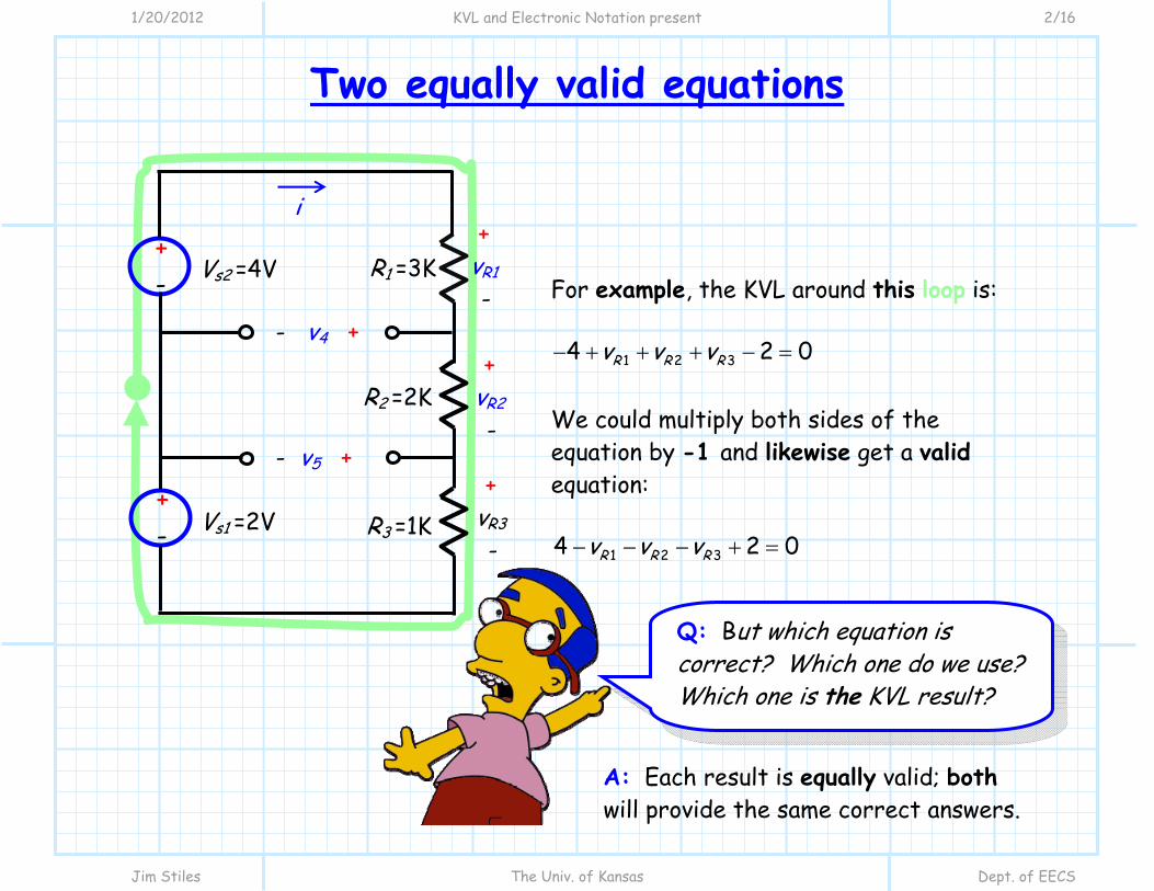
For example, the KVL around this loop is:
1 2 34 2 0R R Rv v v We could multiply both sides of the equation by -1 and likewise get a valid equation:
1 2 34 2 0R R Rv v v
A: Each result is equally valid; both will provide the same correct answers.
Q: But which equation is correct? Which one do we use? Which one is the KVL result?
R1 =3K
R2 =2K
R3 =1K
- v4 +
i
+ vR3 -
Vs2 =4V + -
Vs1 =2V + -
- v5 +
+ vR2 -
+ vR1 -
1/20/2012 KVL and Electronic Notation present 3/16
Jim Stiles The Univ. of Kansas Dept. of EECS
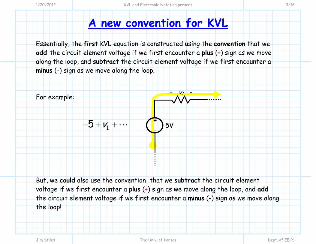
A new convention for KVL Essentially, the first KVL equation is constructed using the convention that we add the circuit element voltage if we first encounter a plus (+) sign as we move along the loop, and subtract the circuit element voltage if we first encounter a minus (-) sign as we move along the loop. For example:
15 v But, we could also use the convention that we subtract the circuit element voltage if we first encounter a plus (+) sign as we move along the loop, and add the circuit element voltage if we first encounter a minus (-) sign as we move along the loop!
+ v1 -
5V + -
1/20/2012 KVL and Electronic Notation present 4/16
Jim Stiles The Univ. of Kansas Dept. of EECS
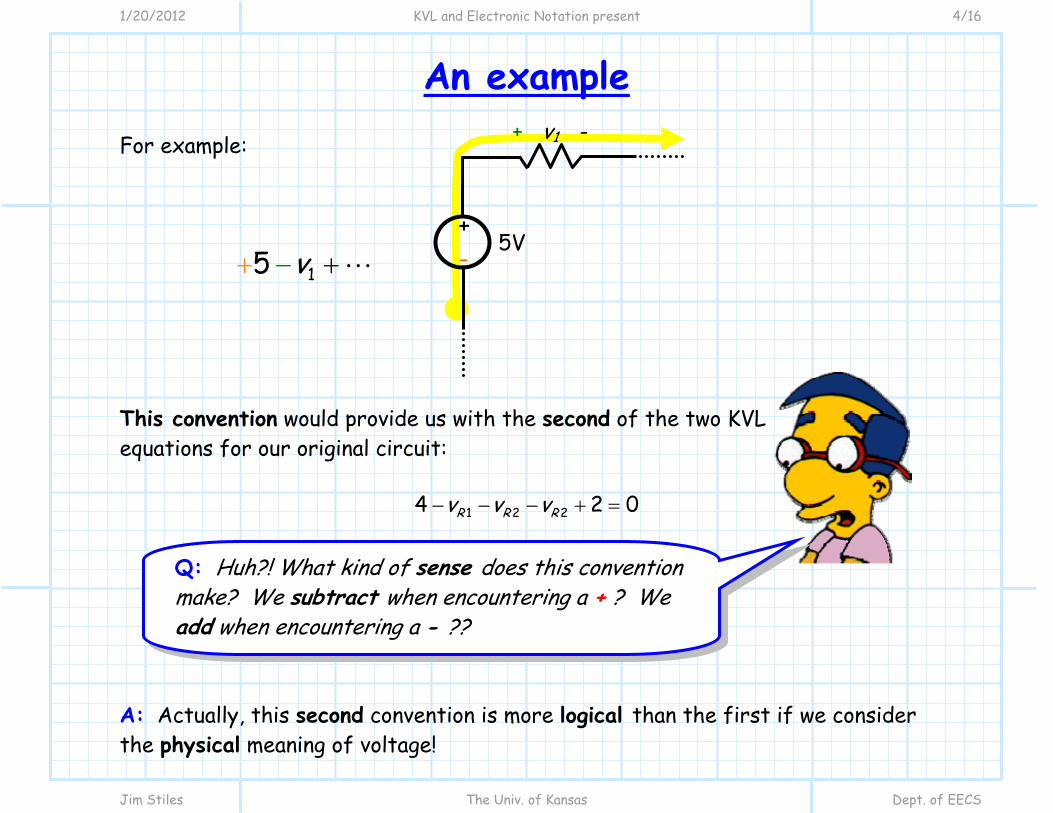
An example For example: 15 v This convention would provide us with the second of the two KVL equations for our original circuit:
1 2 24 2 0R R Rv v v
A: Actually, this second convention is more logical than the first if we consider the physical meaning of voltage!
+ v1 -
5V + -
Q: Huh?! What kind of sense does this convention make? We subtract when encountering a + ? We add when encountering a - ??

1/20/2012 KVL and Electronic Notation present 5/16
Jim Stiles The Univ. of Kansas Dept. of EECS
Let’s keep track of potential energy Remember, “the voltage” is simply a measure of potential energy—the potential energy of 1 Coulomb of charge.
If 1 C of charge were to be transported around the circuit, following the path defined by our KVL loop, then the potential energy of this charge would change as is moved through each circuit element.
In other words, its potential energy would go up, or it would go down.
The second convention describes this increase/decrease!
+ v1 -
5V + -
+ 1C
1/20/2012 KVL and Electronic Notation present 6/16
Jim Stiles The Univ. of Kansas Dept. of EECS
Make this make sense to you
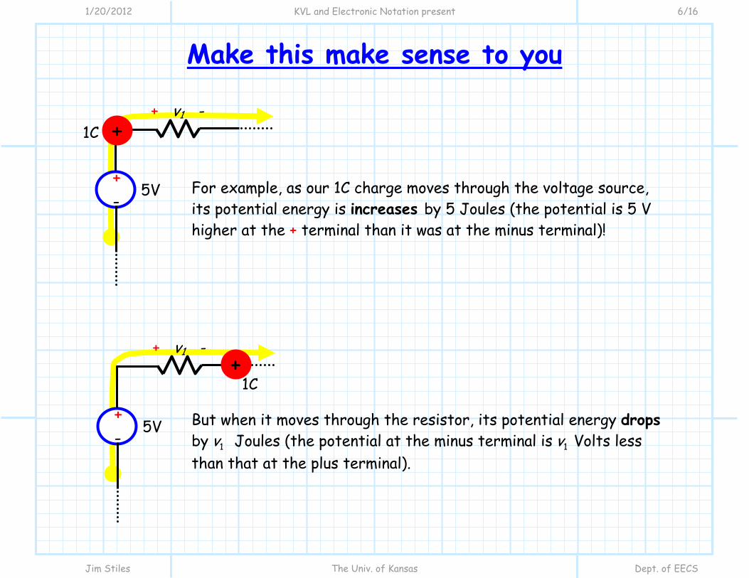
For example, as our 1C charge moves through the voltage source, its potential energy is increases by 5 Joules (the potential is 5 V higher at the + terminal than it was at the minus terminal)! But when it moves through the resistor, its potential energy drops by 1v Joules (the potential at the minus terminal is 1v Volts less than that at the plus terminal).
+ v1 -
5V + -
+ 1C
+ v1 -
5V + -
+ 1C

1/20/2012 KVL and Electronic Notation present 7/16
Jim Stiles The Univ. of Kansas Dept. of EECS
Your parents always wanted you to be an accountant
Thus, the second convention is a more accurate “accounting” of the change in potential! This convention is the one typically used for electronic circuits. You of course will get the correct answer either way, but the second convention allows us to easily determine the absolute potential (i.e., with respect to ground) at each individual point in a circuit.
15 v
+
+ + + v1 -
5V + -

1/20/2012 KVL and Electronic Notation present 8/16
Jim Stiles The Univ. of Kansas Dept. of EECS
Using our new convention To see this, let’s return to our original circuit:
The KVL from these loops are thus:
1 44 0Rv v
2 54 0Rv v v
5 32 0Rv v
1 2 54 0R Rv v v
2 34 2 0R Rv v v
R1 =3K
R2 =2K
R3 =1K
- v4 +
i
+ vR3 -
Vs2 =4V + -
Vs1 =2V + -
- v5 +
+ vR2 -
+ vR1 -

1/20/2012 KVL and Electronic Notation present 9/16
Jim Stiles The Univ. of Kansas Dept. of EECS
We need to define ground Q: I don’t see how this new convention helps us determine the “absolute” potenial at each point in the circuit? A: That’s because we have not defined a ground potential! Let’s do that now:
R1 =3K
R2 =2K
R3 =1K
- v4 +
i
+ vR3 -
Vs2 =4V + -
Vs1 =2V + -
- v5 +
+ vR2 -
+ vR1 -

1/20/2012 KVL and Electronic Notation present 10/16
Jim Stiles The Univ. of Kansas Dept. of EECS
See? We get the same results!
We can thus rewrite this circuit schematic as: Remember that all ground terminals are connected to each other, so we can perform KVL by starting and ending at a ground node:
1 2 34 2 0R R Rv v v 1 44 0Rv v
2 54 0Rv v v The same results as before!
R1 =3K
R2 =2K
R3 =1K
i
+ vR3 -
+ vR2 -
+ vR1 -
Vs =4V - +
Vs =2V - +
+ v 4 -
+ v 5 -

1/20/2012 KVL and Electronic Notation present 11/16
Jim Stiles The Univ. of Kansas Dept. of EECS
Let’s make this really simple
Now, we can further simplify the schematic: Note that we were able to replace the voltage sources with a direct, simple statement about the electric potential at two points within the circuit.
R1 =3K
R2 =2K
R3 =1K
i
+ vR3 -
4.0 V
-2.0V
+ vR2 -
+ vR1 -
v4
v5
The electric potential here must be 4 V!
Vs =2V - +
The electric potential here must be -2 V!
Vs =4V - +

1/20/2012 KVL and Electronic Notation present 12/16
Jim Stiles The Univ. of Kansas Dept. of EECS
This result makes physical sense
Note the KCL equation we determined earlier:
1 2 34 2 0R R Rv v v
Let’s subtract 2.0 from both sides:
1 2 34 2R R Rv v v This is the same equation as before—a valid result from KVL.
Yet, this result has a very interesting interpretation!
R1 =3K
R2 =2K
R3 =1K
i
+ vR3 -
4.0 V
-2.0V
+ vR2 -
+ vR1 -
v4
v5
1/20/2012 KVL and Electronic Notation present 13/16
Jim Stiles The Univ. of Kansas Dept. of EECS
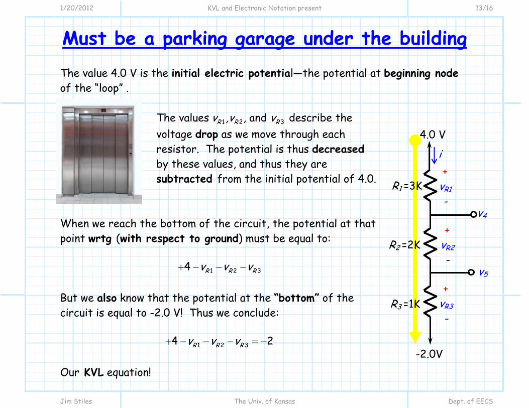
Must be a parking garage under the building The value 4.0 V is the initial electric potential—the potential at beginning node of the “loop” .
The values 1 2 3, and R R Rv ,v v describe the voltage drop as we move through each resistor. The potential is thus decreased by these values, and thus they are subtracted from the initial potential of 4.0.
When we reach the bottom of the circuit, the potential at that point wrtg (with respect to ground) must be equal to:
1 2 34 R R Rv v v
But we also know that the potential at the “bottom” of the circuit is equal to -2.0 V! Thus we conclude:
1 2 34 2R R Rv v v
Our KVL equation!
R1 =3K
R2 =2K
R3 =1K
i
+ vR3 -
4.0 V
-2.0V
+ vR2 -
+ vR1 -
v4
v5

1/20/2012 KVL and Electronic Notation present 14/16
Jim Stiles The Univ. of Kansas Dept. of EECS
This is not rocket science In general, we can move through a circuit written with or electronic circuit notation with this “law”:
The electric potential at the initial node (wrtg), minus(plus) the voltage drop(increase) of each circuit element encountered, will be equal to the electric potential at the final node (wrtg).

1/20/2012 KVL and Electronic Notation present 15/16
Jim Stiles The Univ. of Kansas Dept. of EECS
Just for fun, let’s try this! For example, let’s analyze our circuit in the opposite direction!
Here, the electric potential at the first node is -2.0 volts (wrtg) and the potential at the last is 4.0. Note as we move through the resistors, we find that the potential increases by Rv :
3 2 12 4R R Rv v v
Note this is the effectively the same equation as before:
1 2 34 2R R Rv v v
Both equations accurately state KVL, and either will the same correct answer!
R1 =3K
R2 =2K
R3 =1K
i
+ vR3 -
4.0 V
-2.0V
+ vR2 -
+ vR1 -
v4
v5
1/20/2012 KVL and Electronic Notation present 16/16
Jim Stiles The Univ. of Kansas Dept. of EECS
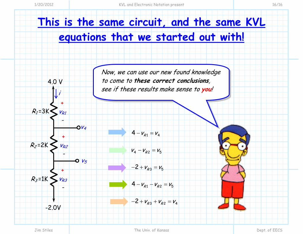
This is the same circuit, and the same KVL equations that we started out with!
1 44 Rv v
2 54 Rv v v
3 52 Rv v
1 2 54 R Rv v v
3 2 42 R Rv v v
Now, we can use our new found knowledge to come to these correct conclusions, see if these results make sense to you!
R1 =3K
R2 =2K
R3 =1K
i
+ vR3 -
4.0 V
-2.0V
+ vR2 -
+ vR1 -
v4
v5

1/20/2012 Analysis of Electronic Circuits present 1/12
Jim Stiles The Univ. of Kansas Dept. of EECS
Analysis of Electronic Circuits
In EECS 211 you acquired the tools necessary for circuit analysis. Fortunately, all those tools are still applicable and useful when analyzing electronic circuits!
Ohm’s Law, KVL and KCL are all still valid, but (isn’t there always a but?) the complicating factor in electronic circuit analysis is the new devices we will introduce in EECS 312. In EECS 211 you learned about devices such as voltage sources, current sources, and resistors. These devices all had very simple device equations:
v i R sv V si I
i
v
R sV
v
i
sI v
i

1/20/2012 Analysis of Electronic Circuits present 2/12
Jim Stiles The Univ. of Kansas Dept. of EECS
Two equally valid equations But (that word again!), in EECS 312 we will learn about electronic devices such as diodes and transistors. The device equations for these new circuit elements will be quite a bit more complicated!
22 GS tD DS DSi K v V v v 1D
Tv
nVSDi I e
Di
Dv
DSv
GSv
iD
G
S
D
1/20/2012 Analysis of Electronic Circuits present 3/12
Jim Stiles The Univ. of Kansas Dept. of EECS
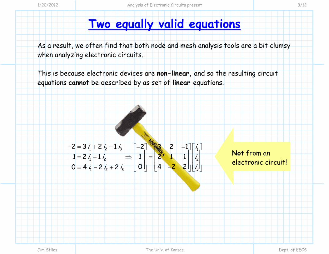
Two equally valid equations As a result, we often find that both node and mesh analysis tools are a bit clumsy when analyzing electronic circuits. This is because electronic devices are non-linear, and so the resulting circuit equations cannot be described by as set of linear equations.
1 2 3
1 2
1 2 3
2 3 2 11 2 10 4 2 2
i i ii ii i i
1
2
3
2 3 2 11 2 1 10 4 2 2
iii
Not from an electronic circuit!
1/20/2012 Analysis of Electronic Circuits present 4/12
Jim Stiles The Univ. of Kansas Dept. of EECS
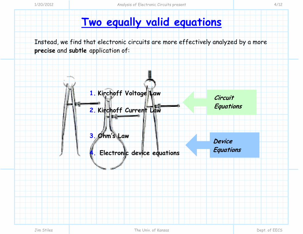
Two equally valid equations Instead, we find that electronic circuits are more effectively analyzed by a more precise and subtle application of:
1. Kirchoff Voltage Law 2. Kirchoff Current Law 3. Ohm’s Law 4. Electronic device equations
Device Equations
Circuit Equations
1/20/2012 Analysis of Electronic Circuits present 5/12
Jim Stiles The Univ. of Kansas Dept. of EECS
Two equally valid equations
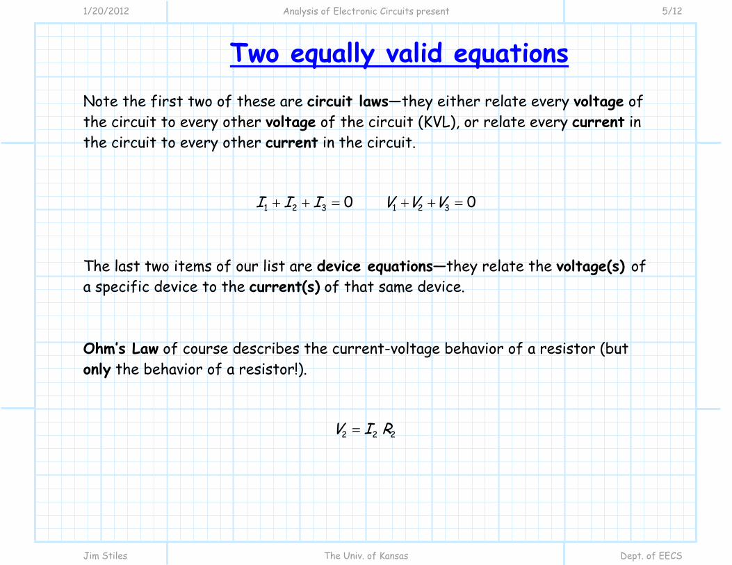
Note the first two of these are circuit laws—they either relate every voltage of the circuit to every other voltage of the circuit (KVL), or relate every current in the circuit to every other current in the circuit.
1 2 3 1 2 30 0I I I V V V
The last two items of our list are device equations—they relate the voltage(s) of a specific device to the current(s) of that same device. Ohm’s Law of course describes the current-voltage behavior of a resistor (but only the behavior of a resistor!).
2 2 2V I R

1/20/2012 Analysis of Electronic Circuits present 6/12
Jim Stiles The Univ. of Kansas Dept. of EECS
Two equally valid equations So, if you:
1. mathematically state the relationship between all the currents in the circuit (using KCL), and: 2. mathematically state the relationship between all the voltages of the circuit (using KVL), and: 3. mathematically state the current-voltage relationship of each device in the circuit, then:
then you have mathematically described your circuit—completely!

1/20/2012 Analysis of Electronic Circuits present 7/12
Jim Stiles The Univ. of Kansas Dept. of EECS
Two equally valid equations
At this point you will find that the number of unknown currents and voltages will equal the number of equations, and your circuit analysis simply becomes an algebra problem! But be careful! In order to get the correct answer from your analysis, you must unambiguously define each and every voltage and current variable in your circuit!!!!!!!!!
1/20/2012 Analysis of Electronic Circuits present 8/12
Jim Stiles The Univ. of Kansas Dept. of EECS
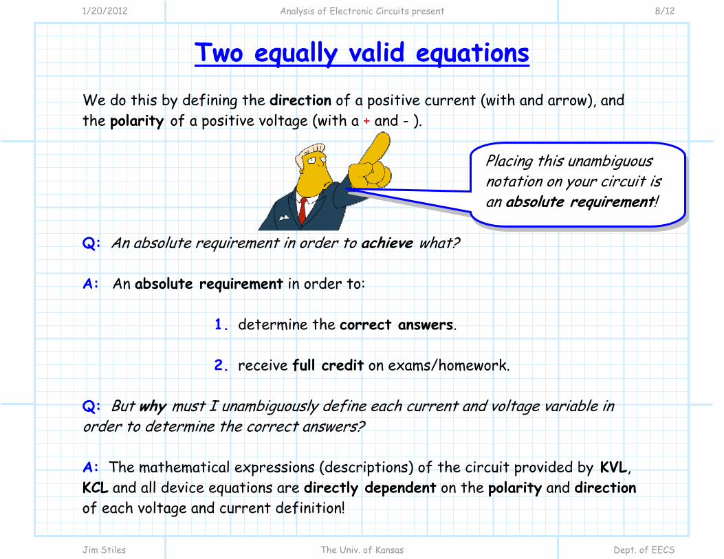
Two equally valid equations We do this by defining the direction of a positive current (with and arrow), and the polarity of a positive voltage (with a + and - ). Q: An absolute requirement in order to achieve what? A: An absolute requirement in order to:
1. determine the correct answers. 2. receive full credit on exams/homework.
Q: But why must I unambiguously define each current and voltage variable in order to determine the correct answers? A: The mathematical expressions (descriptions) of the circuit provided by KVL, KCL and all device equations are directly dependent on the polarity and direction of each voltage and current definition!
Placing this unambiguous notation on your circuit is an absolute requirement!

1/20/2012 Analysis of Electronic Circuits present 9/12
Jim Stiles The Univ. of Kansas Dept. of EECS
Two equally valid equations For example, consider a three current node, with currents
1I , 2I , 3I .
We can of course use KCL to relate these values, but the
resulting mathematical expression depends on how we define the direction of these
currents:
Q: But that’s the problem! How do I know which direction the current is flowing in before I analyze the circuit?? What if I put the arrow in the wrong direction? A: Remember, there is no way to incorrectly orient the current arrows of voltage polarity for KCL and KVL. If the current or voltage is opposite that of your convention, then the numeric result will simply be negative.
1I 2I 3I
1I 2I 3I
1I 2I 3I
1 2 3 0I I I
1 2 3
1 2 3
0I I II I I
1 2 3
1 2 3
0I I II I I

1/20/2012 Analysis of Electronic Circuits present 10/12
Jim Stiles The Univ. of Kansas Dept. of EECS
Two equally valid equations For example, say that in a 3-wire node there is:
3 mA flowing toward the node in wire 1 2 mA flowing toward the node in wire 2 5 mA flowing away from the node in wire 3
Depending on how you define the currents, the numerical answers for 1I , 2I and
3I will all be different, but there physical interpretation will all be the same!
1 2 33 2 5I mA, I mA, I mA
1 2 33 2 5I mA, I mA, I mA
1 2 33 2 5I mA, I mA, I mA
1I 2I 3I
1I 2I 3I
1I 2I 3I

1/20/2012 Analysis of Electronic Circuits present 11/12
Jim Stiles The Univ. of Kansas Dept. of EECS
Two equally valid equations Remember, a negative value of current (or voltage) means that the current is flowing in the opposite direction (or polarity) of that denoted in the circuit. So, without current arrows and voltage polarities, there is no way to physically interpret positive or negative values! Now we know that with respect to KCL or KVL, the current/voltage conventions are arbitrary (it up to you to decide!).
1/20/2012 Analysis of Electronic Circuits present 12/12
Jim Stiles The Univ. of Kansas Dept. of EECS
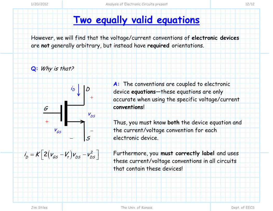
Two equally valid equations However, we will find that the voltage/current conventions of electronic devices are not generally arbitrary, but instead have required orientations. Q: Why is that?
A: The conventions are coupled to electronic device equations—these equations are only accurate when using the specific voltage/current conventions! Thus, you must know both the device equation and the current/voltage convention for each electronic device. Furthermore, you must correctly label and uses these current/voltage conventions in all circuits that contain these devices!
22D GS t DS DSi K v V v v
DSv
GSv
iD
G
S
D