INTRODUCTION - AEP has a long tradition of technical ... 052011 df… · Web viewAISC’s Steel...
39
Proposed SPP Design Best Practices, Performance Criteria, and Scoping Requirements Guidelines for Transmission Facilities Draft Dated May 20, 2011 *NOTE: Insert definition listing of acronyms in the beginning? Introduction This document outlines the Design Best Practices and Performance Criteria (DBP&PC) to be used by the Transmission Owner (TO) when developing Study Estimates for the SPP footprint projects rated at voltages of 100 kV and greater. This will ensure consistently developed project estimates for the Study stage. DBP&PC will promote the development of safe, reliable, and economical transmission facilities using Good Utility Practice as defined in the SPP governing documents . The following document will provide fundamental and guiding principles for transmission design that will minimize the range, impact and length of system outages ; maintain voltage regulation and minimize instability during system disturbances or events ; provide cost-effective solutions; and optimize construction practices . In the event a Design Estimate is outside of the SPP defined acceptable bandwidth, Page 1 of 39
Transcript of INTRODUCTION - AEP has a long tradition of technical ... 052011 df… · Web viewAISC’s Steel...
Proposed SPP Design Best Practices, Performance Criteria, and Scoping
RequirementsGuidelines for Transmission Facilities
Draft Dated May 20, 2011
*NOTE: Insert definition listing of acronyms in the beginning?IntroductionThis document outlines the Design Best Practices and Performance Criteria (DBP&PC) to be used by the Transmission Owner (TO) when developing Study Estimates for the SPP footprint projects rated at voltages of 100 kV and greater. This will ensure consistently developed project estimates for the Study stage.DBP&PC will promote the development of safe, reliable, and economical transmission facilities using Good Utility Practice as defined in the SPP governing documents. The following document will provide fundamental and guiding principles for transmission design that will minimize the range, impact and length of system outages; maintain voltage regulation and minimize instability during system disturbances or events; provide cost-effective solutions; and optimize construction practices.
In the event a Design Estimate is outside of the SPP defined acceptable bandwidth, To establish Design Best Practices and Performance Criteria (DBP&PC) to be used by the SPP’s Transmission Owners (TOs) in developing Study Estimates for SPP footprint projects rated at voltages at 100 kV and greater. These DBP&PC are intended to ensure consistency in TO Study Stage estimates.
The SPP Project Cost Working Group (PCWG) will use the DBP&PC in evaluating those projects (as outlined in the PCWG Charter) and to formulate its recommendation regarding a project to the SPP Board of Directors.
Recognizing the importance of well defined scopes when developing cost estimates, minimumthese scoping requirementsguidelines are provided for the Conceptual and Study estimate phases. These will ensure mutual understanding of the project definition between SPP and the TOs as the project is developed and estimates are prepared for the applicable phase of the potential project.
Page 1 of 28
Williams, Noman, 05/18/11,
Requirements or Guidelines
Kent M. Herzog, 05/20/11,
Poor word choice—implies quantity; perhaps “foundational” would be a better word choice?
Williams, Noman, 05/18/11,
Should just be – recommendation to the BOD
Williams, Noman, 05/18/11,
These seem to be very high and maybe unattainable goals
bkbrown, 05/23/11,
Are we really addressing “system performance” issues or design / cost issues? May not be appropriate in this document.
Williams, Noman, 05/18/11,
?
Williams, Noman, 05/18/11,
This should be SPP OATT
Williams, Noman, 05/18/11,
Need to check SPP documents – not sure we will promote or will provide guidelines.
Jay Caspary, 05/18/11,
Is this accurate? Suggest better wording may be something along the lines of “provide a common foundation to facilitate more consistently”
Kent M. Herzog, 05/20/11,
General comment. There are some references to designing for “10 years out” and some references to designing for “20 years out”. Should those be set to the same?
Larry Streit, 05/20/11,
The communications and protection sections in this document are too specific for the general nature of the remainder of this document. They may reflect one utilities overall practices however there are other practices that are equally acceptable. There are areas in the document that are overly detailed while other areas are vague and very general.

Design Best PracticesDesign Best Practices represent high-level, foundational principles on which sound designs are based. These facilitate the design of transmission facilities in a manner that is compliant with NERC, SPP, and TO requirements; is consistent with Good Utility Practice as defined in the SPP Open Access Transmission Tariff (SPP Tariff)1; is consistent with industry standards such as NESC, IEEE, ASCE, CIGRE, and ANSI; and is cost-effective. Although not addressed here, construction and maintenance best practices must be considered during the design phase to optimize these costs and efficiencies.
Performance CriteriaPerformance Criteria will further define the engineering and design requirements needed to ensure a more uniform cost and reliability structure of the transmission facilities and to ensure that the TOs are constructing the project as requested by SPP. Flexibility is given such that the TO’s historical performance criteria, business processes, and operation and maintenance practices are considered.
Scope ManagementA well developed and rigorously managed scoping document promotes stabilityconsistent estimates and helps control costs. It also ensures that the SPP and TO have a clear understanding of the project being reviewed, and that consistency, economy, and reliability are optimized.
ApplicabilityThe Design Best Practices, Performance Criteria, and Scoping Requirements shall apply to all SPP transmission facilities rated at voltages of 100 kV and greater.
1 The SPP Tariff defines Good Utility Practice as follows: “Good Utility Practice: Any of the practices, methods and acts engaged in or approved by a significant portion of the electric utility industry during the relevant time period, or any of the practices, methods and acts which, in the exercise of reasonable judgment in light of the facts known at the time the decision was made, could have been expected to accomplish the desired result at a reasonable cost consistent with good business practices, reliability, safety and expedition. Good Utility Practice is not intended to be limited to the optimum practice, method, or act to the exclusion of all others, but rather to be acceptable practices, methods, or acts generally accepted in the region, including those practices required by Federal Power Act section 215(a)(4).”
Page 2 of 28
Jay Caspary, 05/18/11,
Should we focus our efforts initially on 200kV+ and then provide similar guidelines regarding other facilities as appropriate. Also, what do we do about 69 and 34 kV facilities that are under SPP’s planning authority and tariff administration? Suggest that we provide a milestone upfront and adjust as necessary?
Larry Streit, 05/20/11,
It would be difficult to develop a single set of requirements that would equally apply to this voltage range. Separation should be made between facilities which function primarily for distribution which may be lightly loaded vs heavily loaded EHV transmission systems
bkbrown, 05/23/11,
Should we start with 345 kV projects? 100 kV projects are likely local zonal funded projects and much lower cost than 300+ kV projects which minimizes exposure to cost based risks.
Williams, Noman, 05/18/11,
Not sure reliability is optimized
Williams, Noman, 05/18/11,
What type of stability? Cost?
Larry Streit, 05/20/11,
Again there are areas in this document that are too specific and do not allow the flexibility that this paragraph provides
Williams, Noman, 05/18/11,
We need to be careful from a regional view not to define maintenance practices
Design Best Practices
Transmission Lines
GeneralAny criteria established for the design of transmission lines must consider safety, reliability, operability, maintainability, and, economic impacts. The NESC contains the basic provisions considered necessary for the safety of utility personnel, utility contractors, and the public. However, the NESC is not intended to be used as a design manual, so Good Utility Practice must also be considered.., as well as RUS guidelines where applicable.
Siting and RoutingThe impact of the transmission facility to the surrounding environment should be considered duringwhen developing the routing processstudy estimate. Sensitivity to wetlands, cultural and historical resources, endangered species, archeological sites, existing neighborhoods, and federal lands, among others, are examples that should be considered when siting transmission facilities. The TO must comply with the requirements of all appropriate regulatory agencies during the siting process, and all applicable environmental and regulatory permits must be obtained for the transmission facilities. The TO should describe any known environmental issues and associated estimated costs in its Study Estimate, as well as any estimated regulatory siting and permitting costs. Initial study estimates will use a default assumption for line mileage that is 125% of straight line based upon right angle design absent better assumptions from the TO. as detailed in the Standardized Cost Estimate Reporting Template (SCERT) that is in development by the PCWG. *Note: Address multiple TO projects.
Electrical ClearancesThe clearances of the NESC shall be adhered to in the design of transmission lines. Conductor-to-ground and conductor-to-conductor clearances should include an adequate margin during design to account for tolerances in surveying and construction. Sufficient climbing and working space for NESC and OSHA working clearances should be considered when establishing the geometrical relationships between structure and conductors. Where applicable, dynamic effects (e.g. galloping conductors, ice-drop, etc.) shall be considered.
Structure Design LoadsASCE Manual of Practice No. 74, Guidelines for Electrical Transmission Line Structural Loading (ASCE MOP 74), should be used as the basis for the selection of wind and ice loading criteria. A minimum 50-year mean return period shall be used. To provide for infrastructure hardening and increased reliability, or if warranted by the TO’s historical weather data and operating experience, a larger mean return period should be considered. If a larger mean return period is used, it should be denoted in the Study Estimate.
Page 3 of 28
Keeler, Erin, 05/18/11,
Agree with this comment being included.
Kent M. Herzog, 05/20/11,
NESC?
Williams, Noman, 05/18/11,
And RUS for cooperatives
Kent M. Herzog, 05/20/11,
What about designing for “hot work”?
Williams, Noman, 05/18/11,
Need to include RUS guidelines
Jay Caspary, 05/18/11,
Should we designate expectations regarding high capacity, backbone transmission lines in SPP, e.g., 5000 Amps in ERCOT CREZ, minimum line segment lengths of 100 miles unless approved in advance by PCWG or similar committee at SPP, etc.
Kent M. Herzog, 05/20/11,
Should anything be included on electrical effects (RI, TVI or EMF)?
Keeler, Erin, 05/18/11,
Feel the format should be changed to numbering. For example: Transmission Lines General Siting and Routing . . . Transmission Substations Or something similar to this. It would be easier to reference a certain section in the future or if there are questions.
Structures will be designed, at a minimum, to the NESC and in accordance to the TO’s past practices, as appropriate.
Structure and Foundation Selection and DesignStructure types may be either latticed steel towers, steel or concrete tubular poles or wood for facilities 200 kV and above. Wood structures may be used for voltages below 300 kV at the TO’s discretion (At SPS we have hundreds f miles of 230 on wood poles. We do not intend to unilaterally change that). . The choice should be based on consideration of structural loading, phase configuration, total estimated installed cost and other economic factors, aesthetic requirements, siting restrictions, and right-of-way requirements, and availability of local labor skills..
Structure design shallcan be based on the following as they apply:
ASCE Standard No. 10, Design of Latticed Steel Transmission Structures
ASCE Standard No. 48, Design of Steel Transmission Pole Structures
ASCE Publication Guide for the Design and Use of Concrete Poles
ANSI 05-1, Specifications and Dimensions for Wood Poles
IEEE Std. 751, Trial-Use Design Guide for Wood Transmission Structures
Structures may be foundedsupported on concrete piers, grillages, or piles, or they may be directly embedded. The method selected shall be based on known geotechnical conditions,, and structure loading, economics, and availability of local labor skills..
Insulation Coordination, Shielding, GroundingMetallic transmission line structures shall be grounded. Overhead static wires (shield wires) should also be directly grounded, or a low impulse flashover path to ground should be provided by a spark gap. Individual structure grounds should be coordinated with the structure insulation level and static wire shielding angles (with reference to the phase conductors) to limit momentary operations of the supported circuit(s) to the targeted rate. The coordination of grounding, shielding and insulation should be established considering the effects of span lengths, conductor-to-ground clearances, lightning strike levels, and structure heights.
Rating of Phase ConductorsThe maximum operating temperature of phase conductors should be based on metallurgical capacity (i.e., the maximum temperature the conductor can withstand without incurring damage due to heat) and assuming a reasonable loss of strength.
The conversion to ampacity shall be based on the IEEE Publication No. 738 Standard for Calculating the Current-Temperature of Bare Overhead Conductors. The TO should select environmental parameters based on its experience and historical line rating and operating procedures. *Note: AI (SPP) to find out the SPP criteria for conductor rating and selection.
Page 4 of 28
Williams, Noman, 05/18/11,
Should we not follow the SPP rating criteria?
rlw0209, 05/20/11,
OG&E comments We do currently ground all our 345kV structures including the steel structures. However, we do not directly bond/ ground via a separate jumper the static (shield) wire or OPGW. We rely on the metal to metal contact between the shield wire &/or OPGW and the metallic suspension hardware which is bolted to the metal structure. Although directly bonding/ grounding the shield/ OPGW at every structure is desirable, it would increase costs and our OPGW manufacturer told us that about ½ of the utilities do so and about ½ do not. We have not had any issues with our current mode of operation.
Williams, Noman, 05/18/11,
Are we requiring geotech investigation? How is this related to a study estimate?
Williams, Noman, 05/18/11,
Do we want to reference a wood pole design guide?
Williams, Noman, 05/18/11,
Are we eliminating the use of wood for 230-kV or above? Wood should remain and option up to 345-kV
bkbrown, 05/23/11,
Is steel towers vs. wooden H-Frame construction a standard for all current SPP members?
Selection of Phase ConductorsPhase conductors should be selected to meet Performance Criteria requested by SPP and based on the anticipated power flow of the circuit, metallurgical and mechanical properties and proper consideration for the effects of the high electric fields.
ReconductoringTOs will consider the application of advanced conductors for reconductoring projects if existing structures are adequate and have sufficient life expectancy to preclude tear down and rebuilds.
Optical Ground WireOptical Ground Wire (OPGW) is preferred for all overhead shield wires to provide a communication path for the transmission system. (Does this mean that if you have 2Where there are multiple static wires on a line that bothonly one should be OPGW. Where there is an underground fiber? This will become cost-prohibitive) communication path OPGW is not preferred. The size shall be determined based on the anticipated fault currents generating from the terminal substations...
*NOTE:Reactive Compensation
For project cost estimates line mileage greater than 100 miles should include cost estimates for reactive compensation.
Page 5 of 28
Williams, Noman, 05/18/11,
Not sure if this is part of the design best practice or a preference
Keeler, Erin, 05/18/11,
Don’t feel that this should be required for all lines. It gets to be extremely pricey for long lines. It would be our preference for shorter lines.
Larry Streit, 05/20/11,
Many companies use underground fiber optic systems rather than OPGW. Is OPGW an absolute requirement? If structures include multiple shield wires do they all need to be OPGW
bkbrown, 05/23/11,
This may not be acceptable to utilities that are prone to heavy ice loading resulting in shield wire damage and loss of communications.
Kent M. Herzog, 05/20/11,
We think OPT-GW should be required on all new construction; considering the nominal cost difference.
Transmission Substations
GeneralAny criteria established for the design of transmission substations must consider safety, reliability, operability, maintainability, and, economic impacts. The NESC contains the basic provisions considered necessary for the safety of utility personnel, utility contractors, and the public. However, the NESC is not intended to be used as a design manual, so Good Utility Practice must also be considered, as well as RUS guidelines where applicable.
Substation Site Selection and PreparationWhen selecting the substation site, careful consideration must be given to factors such as line access and right-of-way, vehicular access, topography, geology, grading and drainage, environmental impact, and plans for future growth. Each of these factors can affect not only the initial cost of the facility, but its on-going operation and maintenance costs.
Site design must ensure that the substation pad is large enough to accommodate the footprint of the equipment layout inside the fence, while maintaining adequate drive paths throughout the substation to safely operate and replace/maintain the equipment. The pad should extend outside the fence to allow for proper grounding and step and touch protection. The pad shall be crowned or sloped to facilitate drainage. The finished elevation of the substation pad should be as a minimum at least 1’ above the elevation of the 100-year flood.
The substation site should be designed to be as maintenance free as possible. Cut and fill slopes, including ditches and swales, should be stable and protected from erosion using best management practices. Storm water management plans and structures must comply with all federal, state, and local regulations.
Page 6 of 28
Jay Caspary, 05/18/11,
Similar to JC3, include provisions for high capacity, EHV substations which will support high capacity, backbone lines to provide an effective and efficient overlay for SPP and neighbors in the long term. For example, ERCOT CREZ substations in the plains were 160 acre sites. Similar guidelines should be considered and applied, as appropriate, in initial design and estimates to support SPP’s long term needs.
Kent M. Herzog, 05/20/11,
A requirement should be added that disturbance monitoring equipment should meet SPP Criteria/NERC standards.
Kent M. Herzog, 05/20/11,
This section should include something on metering and monitoring/control (RTU) requirements as well as event retrieval.
GroundingThe substation ground grid should be designed in accordance with the latest version of IEEE Std. 80, Guide for Safety in AC Substation Grounding. The grid should be designed using the maximum fault current expected when considering the ultimate one-line build-out.for the life of the facility.
Bus Arrangements and Substation ShieldingSwitching substations with ultimatelyan ultimate layout of four lines or less should be designed with a ring bus configuration and switching substations with an ultimate layout of more than four lines should be designed with a breaker-and-a-half configuration. The substation graded area should be designed for future expansion requirements expected within the next 10 years. . All bus and equipment should be protected from direct lightning strikes using an acceptable analysis method such as the Rolling Sphere Method. IEEE Std. 998, Guide for Direct Lightning Stroke Shielding of Substations, may be consulted for additional information.
Bus Selection and DesignBus selection and design must take into consideration the electrical load (ampacity) requirements to which the bus will be subjected, in addition to structural loads such as gravity, ice, wind, short circuit forces, and thermal loads. Bus conductor and hardware selection are also critical to acceptable corona performance and the reduction of electromagnetic interference. Allowable span lengths for rigid-bus shall be based on both material strength requirements of the conductor and insulators, as well as acceptable bus deflection limits. Guidelines and recommendations for bus design can be found in IEEE Std. 605, Guide for the Design of Substation Rigid-Bus Structures.
Bus conductors should be sized for the maximum anticipated load (current) calculated under various planning conditions and contingencies. To prevent the ampacity rating of substation bus from limiting system capacity, bus ratings should allow full capacity of the line ratings. Bus ratings should typically exceed the nameplate rating of transformers by 35 to 50 percent to allow usage of and provide for the overload capacity of the transformer.
Rating of Bus ConductorsThe maximum operating temperature of bus conductors should be based on metallurgical capacity (i.e., the maximum temperature the conductor can withstand without incurring damage due to heat) and assuming a reasonable loss of strength.
The conversion to ampacity shall be based on the IEEE Std. 738, Standard for Calculating the Current-Temperature of Bare Overhead Conductors, and IEEE Std. 605, Guide for the Design of Substation Rigid-Bus Structures. The TO should select environmental parameters based on its experience and historical line rating and operating procedures. *Note: AI (SPP) to find out the SPP criteria for conductor rating and selection.
Page 7 of 28
Jay Caspary, 05/18/11,
Shouldn’t this be expanded to focus on how we will rate the buswork in substations and lines in general. Some members rate lines as if substations have breakers in a ring bus for example out of service, while others do not, which affects required upgrades in our plans. This seems to be an important and timely topic for the DBPPCTF, especially for high capacity EHV lines and substations noted in JC3 and JC4.
Kent M. Herzog, 05/20/11,
What exactly is intended by this statement referring to transformers? Autotransformers? Power transformers?
bkbrown, 05/23/11,
Is this a criteria or a recommendation. Should is simply state that this should “be considered” in the design.
Williams, Noman, 05/18/11,
Need to include RUS standards
Larry Streit, 05/20/11,
Divide into Bus Arrangement and Substation Shielding as two topics. Many companies use 6 terminals as the dividing line between a ring bus and a breaker-and-a half configuration especially for lower voltages. Highly loaded and high reliability substations may need to be breaker-and-a-half when over four terminals. It could be difficult to expand many existing sites to breaker-and-a -half. Consideration should be given to loading, voltage level, and reliability needs along with associated costs
Jay Caspary, 05/20/11,
EMDE suggests striking this sentence.
bkbrown, 05/23/11,
What information is used to determine future development needs?
Jay Caspary, 05/18/11,
This is likely not adequate for high capacity, EHV substations.
Williams, Noman, 05/18/11,
I do not agree with this bus configuration for 115 & 138 kV stations.
bkbrown, 05/23/11,
NPPD’s criteria is 6 lines before going to breaker-and-a-half configuration but we could support the 4 line criteria. Will it be a requirement to build ring bus in a configuration easily converted to a breaker-and-a-half scheme (folded ring) to account for possible future expansion.
Jay Caspary, 05/20/11,
EMDE suggests “six”, not “four”, and carryover to page 15
Larry Streit, 05/20/11,
Suggest a longer horizon of time as upgrading ground grids are difficult and a short horizon requires frequent calculations
Substation EquipmentFuture improvements should be considered when sizing equipment.
Surge protection shallshould be applied, where appropriate, on all line terminals with circuit breakers and considered on all oil-filled electrical equipment in the substation such as transformers, instrument transformers and power PTs.
All substation equipment should be specified such that audible sound levels at the edge of the substation property do not exceed the lesser of 65 dBA or as required by local ordinance. Is this overly restrictive for rural substation installations?are appropriate to the facility’s location.
Substation ServiceThere should be two sources of AC substation service for preferred and back-up feeds. Some acceptable substation service alternatives would be to feed the substation service transformers via the tertiary winding of an autotransformer or connect power PTs to the bus. Distribution lines should not be used as the primary AC source because of reliability concerns, but can be used as a back-up source when other sources are unavailable. If there are no good alternatives for a back-up substation service, installation of a generator shouldcould be installed. A throwover switch should be installed between the preferred and back-up feeds.considered.
Structure and Foundation Selection and DesignStructures and foundations should be designed for all loads acting on the structure and supported bus or equipment, including forces due to gravity, ice, wind, line tension, fault currents and thermal loads.
Structures may be designed and fabricated from tapered tubular steel members, hollow structural steel shapes, and standard structural steel shapes. No permanent wood pole structures should be allowed. SPS has used wood poles for SCADA radio antenna installations. The selection of structure type (e.g., latticed, tubular, etc.) should be based on consideration of structural loading, equipment mounting requirements, total estimated installed cost and other economic factors, and aesthetic requirements and availability of local labor skills.
Structure design shallshould be based on the following, as appropriate:
ASCE Standard No. 10, Design of Latticed Steel Transmission Structures
ASCE Standard No. 48, Design of Steel Transmission Pole Structures
ASCE Standard No. 113, Substation Structure Design Guide
AISC’s Steel Construction Manual
Page 8 of 28
Kent M. Herzog, 05/20/11,
What about the ASCE Substation Structure Design Guide?
Larry Streit, 05/20/11,
Why is cost mentioned here when not included in most other requirements in this document?
Kent M. Herzog, 05/20/11,
Any PQ and/or reliability concerns with this? Regulation? Grounding concerns? Exposure to autotransformer?
Larry Streit, 05/20/11,
Divide paragraph into surge protection and sound levels..
Jay Caspary, 05/20/11,
EMDE seeks clarification on application. What is considered “protected”?
Larry Streit, 05/20/11,
Surge arresters are typically not installed on instrument transformers or power PTs.
Jay Caspary, 05/18/11,
Isn’t this “shall” based on Good Utility Practice?
Structures may be foundedsupported on concrete piers, spread footings, slabs on grade, piles, or they may be directly embedded. The method selected shall be based on geotechnical conditions, structure loading, and obstructions (either overhead or below grade), economics and the availability of local labor skills.).
Control BuildingsControl buildings may be designed to be erected on site, or they may be of the modular, prefabricated type. Buildings shallmay be constructed of: steel, block, or other alternative materials, and should be designed and detailed in accordance with the applicable sections of the latest edition of (*NOTE find design standards for buildings made of materials other than steel) the AISC Specification for Structural Steel Buildings. Light gauge structural steel members may be designed and detailed in accordance with the latest edition of the AISI Specification for the Design of Cold-Formed Steel Structural Members.
Design loads and load combinations shallshould be based on the requirements of the International Building Code or as directed by the jurisdiction having authority. Building components shall also be capable of supporting all cable trays and attached equipment such as battery chargers and heat pumps.
Wall and roof insulation shallshould be supplied in accordance with the latest edition of the International Energy Conservation Code for the applicable Climate Zone.
Oil ContainmentSecondary oil containment shall be provided around oil-filled electrical equipment and storage tanks in accordance with the requirements of the United States EPA. More stringent provisions may be adopted to further minimize the collateral damage from violent failures and minimize clean-up costs.2
Phase Measurement Units (PMUs
)PMUs shallor Intelligent Electronic Devices (IEDs) should be installed in all new 230 kV+ and above substations. *NOTE: AI (SPP) will research what we have now.
Single Pole Switching / Breakers / Controls
2
? Additional design information can be found in IEEE Std. 980, Guide for Containment and Control of Oil Spills in Substations.
Page 9 of 28
Jay Caspary, 05/20/11,
EMDE recommends “shall” be changed to “should”
Larry Streit, 05/20/11,
The wind loading of the building should exceed the wind loading requirements of the substation structures.
Jay Caspary, 05/20/11,
EMDE suggests a global change of “Building” to “Enclosure”
Kent M. Herzog, 05/20/11,
What about reference to ASCE 7?
Kent M. Herzog, 05/20/11,
Is it worth specifically mentioning that control buildings should be properly grounded and anchored to foundation?

All 500kV+ and above facilities in SPP will be designed to accommodateshould consider single pole switching. The application of single pole switching to UHV facilities should facilitate maintenance, improve grid stability and performance, and potentially accommodate future changes to existing reliability metrics and standards that could provide tremendous benefit to SPP customers without sacrificing system reliability. Consideration of single pole switching for select 345 kV facilities is encouraged to the extent itsit is warranted.
Page 10 of 28
Transmission Protection and Control Design
GeneralBest practices for employing protection and control principles in the design and construction of new substations must adhere to NERC Reliability Standards, and SPP Criteria, and its other governing documents. .as well as individual TO standards.
These guiding principles and best practices center on the following criteria:
Communication Systems
Voltage and Current Sensing Devices
DC Systems
Primary and Backup Protection Schemes
Communication SystemsPower Line Carrier (PLC) equipment or fiber as the communication medium in these pilot protection schemes is recommended to meet the high-speed communication required. PLC equipment is typically used on existing transmission lines greater than five miles in length. Fiber protection schemes () should be considered on all new transmission lines being constructed using OPGW. Relays manufactured from the same vendor must be installed at both ends of the line when fiber protection is being considered. The same relay vendor shall be used if required by the type of relay scheme chosen for PLC (e.g., directional comparison blocking). *NOTE: Add in other forms or Comm; microwave, tone.
Voltage and Current Sensing DevicesIndependent current transformers (CTs) are recommended for primary and backup protection schemes in addition to independent secondary windings Not typical for current SPS designsofof the same voltage source (i.e., CCVTs).
DC Systems to Yard Equipment TerminalsCareful consideration must be applied to DC systems as redundancy requirements and should be designed in accordance with NERC standards evolve. Dual batteries are required for 345 kV and above, SPP criteria, and TO practices.
Primary and Backup Protection SchemesPrimary and backup protection schemes shall be required for all lines and must be capable of detecting all types of faults on the line. The primary scheme must provide high-speed, simultaneous tripping of all line terminals at speeds that will provide fault clearing times for system stability as defined in NERC Transmission Planning and Reliability Standards TPL-001 through TPL-004. Consideration for two different relay vendors shall also be required when
Page 11 of 28
Larry Streit, 05/20/11,
Recommend removing the reference to NERC
Kent M. Herzog, 05/20/11,
Directional comparison blocking schemes are inherently biased to over trip for failure of the PLC or channel. In the current and future NERC environment, this may no longer be acceptable.
Kent M. Herzog, 05/20/11,
Automatic check back of carrier used for DCB schemes only ensures that the carrier is working at the time of the test, not at all times. DCUB schemes using frequency shift carrier with continuous monitoring would be a better choice.
Kent M. Herzog, 05/20/11,
Lines should be limited to two terminals for reliability.
Kent M. Herzog, 05/20/11,
It should be permissible to use primary and secondary relays from the same vendor if they utilize different operating principles, i.e. distance, current differential, etc.
Larry Streit, 05/20/11,
Recommned removing the reference to NERC
Kent M. Herzog, 05/20/11,
Depending on line length, overvoltage protection due to the Ferranti Effect should be installed.
Kent M. Herzog, 05/20/11,
We believe that three single phase voltage devices (VTs or CVTs) should be required on each line at a substation.
Larry Streit, 05/20/11,
This is too specific and too limiting to be a general requirement for all voltage classes and situations. Many companies use underground fiber systems in place of OPGW
Keeler, Erin, 05/18/11,
Don’t feel that this should be required for ALL lines due to cost. We suggest for lines up to 60 miles in length.
Kent M. Herzog, 05/20/11,
Depending on location, digital microwave and even leased circuits may be acceptable as a communication medium for protection.
Williams, Noman, 05/18/11,
This does not make sense
Williams, Noman, 05/18/11,
Who?
Williams, Noman, 05/19/11,
General comment, - is this getting to specific on how and what we use for control and protection? This also appears to require the use of fiber optic systems which may not be a reasonable requirement.

selecting each relay system. . This is considered established practice and eliminates a common mode of failure should a problem appear in one relay system.
The following criteria shall be used to determine if one or two high speed protection systems are needed on a line. While it is possible that the minimum protective relay system and redundancy requirements outlined below could change as NERC Planning and Reliability Standards evolve, it will be the responsibility, of each individual TO, to assess the protection systems and make any modifications that they deem necessary for transmission construction on its system.
500 / 765 kV Line ApplicationsAt least two high speed pilot schemes and dual direct transfer trip (DTT) using PLC and/or fiber are required. Fiber shall be used on all new transmission lines using OPGW and PLC equipment for existing lines (Mode 1 coupling to all three phases). PLC-based protection schemes using directional comparison blocking (DCB) require automatic checkback features to be installed to ensure the communication channel is working properly at all substations.
345 kV Line Applications (SPS suggestes this be for 300 kV and above. This is not what we would do on our 230 kV lines)Dual high speed pilot schemes and one direct transfer trip (DTT) using PLC and/or fiber are required. Dual DTT is required if remote breaker failure protection cannot be provided with relay settings. Fiber shall be used on all new transmission lines using OPGW and PLC equipment for existing lines. The meaning of this statement is not completely clear, but I would use the word should rather than shall) Independent PLC communication paths may be required for proper protective relay coordination. PLC-based protection schemes using directional comparison blocking (DCB) require automatic checkback features to be installed to ensure the communication channel is working properly at all substations.
Below 300 kV Line ApplicationsA minimum of one high speed pilot scheme using PLC and/or fiber is required. Fiber shall be used on all new transmission lines using OPGW and PLC equipment for existing lines. Dual pilot schemes may be required for proper relay coordination. If dual high speed systems are needed, independent communication channels will be used. PLC-based protection schemes using directional comparison blocking (DCB) require automatic checkback features to be installed to ensure the communication channel is working properly at all substations.
Page 12 of 28
Larry Streit, 05/20/11,
Other schemes should be considered
bkbrown, 05/23/11,
Based on earlier comments, this section could be eliminated.
Keeler, Erin, 05/18/11,
Same comment as above. We need to evaluate what is best for each project.
Kevin Wray Jones, 05/23/11,
Forcing us to use fiber. What if we have a new long 115 kV line and we don’t want to spend the money on fiber because PLC is more economical???
Jay Caspary, 05/20/11,
EMDE recommends changing “shall” to “should”
Kent M. Herzog, 05/20/11,
I don’t know about 115 or 138 kV, but we require that 161 kV circuits have direct transfer trip for equipment/breaker failure protection.
Keeler, Erin, 05/18/11,
Should not be required. We need to be able to evaluate the best relay communication scheme for each installation.
Kent M. Herzog, 05/20/11,
It has been utility practice in MAPP/MRO to utilize dual direct transfer trip as well as dual high speed pilot schemes on 345 kV. Some utilities have done so at 230 kV as well.
Larry Streit, 05/20/11,
Recommend removing reference to NERC
Jay Caspary, 05/20/11,
EMDE recommends striking this sentence if the above change is not made.
Keeler, Erin, 05/18/11,
The same manufacturer should be able to be used for both schemes if different relay principles are used for each scheme.
Larry Streit, 05/20/11,
Recommend removing the requirement for different vendors – although some utilities may have experience problems in the past, proper vendor selection should eliminate this problem. Multiple vendors also introduce training issues, software upgrade issue
Jay Caspary, 05/20/11,
EMDE recommends stricking this sentence, unless “vendors” is changed to “types”.
Kevin Wray Jones, 05/23/11,
SPS uses two different relay types of the same manufacturer. This doesn’t say we HAVE to use two different vendors, only CONSIDER it.
Performance Criteria
Page 13 of 28

Transmission Lines
Electrical ClearancesThe clearances of the NESC shall be adhered to as a minimum in the design of transmission lines. Conductor-to -ground and conductor-to-conductor clearances should include a two-foot
minimum margin during design to account for tolerances in surveying and construction.
Appropriate clearances should be maintained considering legislative loads, NESC requirements maximum operating temperature, and extreme ice loading. Conductor-to-conductor clearances should also include extra clearance to account for sag and tension, wire movement variances, and minimum approach distances.
Design Load ApplicationStructures and foundations should be designed to withstand a combination of gravity, wind, ice, conductor tension, construction, and maintenance loads. The following base loadings recommended by ASCE Manual of Practice (MOP) 74 shallshould be considered to help ensure structural integrity under most probable loading combinations. Dynamic loading (e.g. galloping, ice-drop, etc.) of conductors should also be considered.
Loads with All Wires Intact NESC requirements
Extreme wind applied at 90º to the conductor and structure
Extreme wind applied at 45º to the conductor and structure
Combined wind and ice loadings
Extreme ice loading
Unbalanced Loads Longitudinal loads due to unbalanced ice conditions (ice in one span, ice fallen off of
adjacent span) with all wires intact
Longitudinal loads due to a broken ground wire or one phase position (the phase may consist of multiple sub-conductors)
Unbalanced loads should be considered to prevent cascading failure with spacing not to exceed two miles or 10 structurespredicated on T. O. practices
Construction and Maintenance Loads Construction and maintenance loads shall be applied based on the recommendations of
ASCE MOP 74 These loads may be modified based on local TO construction, maintenance, and safety practices
Page 14 of 28
Kent M. Herzog, 05/20/11,
What is this referring to? “Storm structures”? Every 2 miles?
Keeler, Erin, 05/18/11,
Or using the TO’s historical practice. We have a terminal structure every 3 miles and a full storm structure every 5 miles.
rlw0209, 05/20/11,
OG&E Comments: they are calling for full tension dead-end structures every 2 miles or for a maximum of 10 structures between. Our current philosophy is 10 – 12 miles for single circuit and 8-10 miles for double circuit lines. We could possibly lower ours to 5-6 miles for single circuit and 2-4 for double circuit, but it WILL DEFINITELY FORCE HIGHER COSTS
Kent M. Herzog, 05/20/11,
What about normal service loads for aesthetics?
Jay Caspary, 05/20/11,
EMDE wonders if “should” is be than “shall”
Larry Streit, 05/20/11,
?????
bkbrown, 05/23/11,
Need to verify.
Williams, Noman, 05/19/11,
? - basis
Williams, Noman, 05/19/11,
Need to consider RUS standards
Kent M. Herzog, 05/20/11,
What about clearances under structure deflection?
Kent M. Herzog, 05/20/11,
What about foundations? Strength? Deflection?

Static Rating of Phase ConductorsThe maximum operating temperature of phase conductors shall be based on metallurgical capacity (i.e., the maximum temperature the conductor can withstand without incurring damage due to heat) and assuming a reasonable loss of strength.
The conversion to ampacity shall be based on IEEE Publication No. 738, Standard for Calculating the Current-Temperature of Bare Overhead Conductors. Each utility should use and document the criteria as a default, absent other assumptions that fits their service territory. Following are the criteria that mustappropriate, e.g, wind speed in plains may be specifiedhigher.
Winter Ambient Temperature:
Summer Ambient Temperature:
Wind Velocity:
Wind Direction:
Emissivity Factor:
Solar Absorption Factor:
Angle of Sun’s Rays:
Elevation:
Dynamic Rating of Phase ConductorsTOs are encouraged to consider dynamic rating of phase conductors, as appropriate, for new and existing lines.
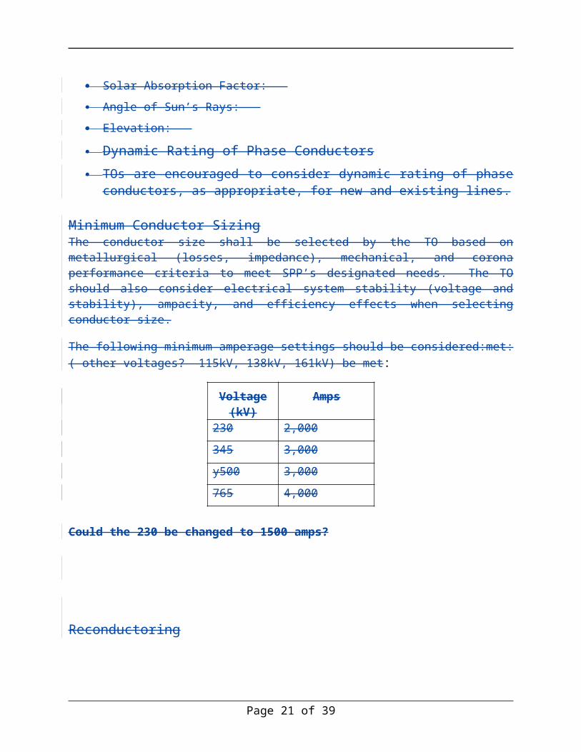
Minimum Conductor SizingThe conductor size shall be selected by the TO based on metallurgical (losses, impedance), mechanical, and corona performance criteria to meet SPP’s designated needs. The TO should also consider electrical system stability (voltage and stability), ampacity, and efficiency effects when selecting conductor size.
The following minimum amperage settings should be considered:met: ( other voltages? 115kV, 138kV, 161kV) be met:
Voltage (kV)
Amps
230 2,000
345 3,000
y500 3,000
765 4,000
Page 15 of 28
bkbrown, 05/23/11,
This is extreme for 230 kV. This is nearly 800 MVA. NPPD does not have standard conductors with this high of capacity. This would force the use composite conductor which is way to much cost for what a 230 kV facility will ever carry. 1200 Amps seems like a more reasonable minimum.
Kevin Wray Jones, 05/23/11,
Does this force us to use bundled 795 on all 230 kV lines???
Williams, Noman, 05/19/11,
Should 115/138-kV also be included? 1,200 Amps
Jay Caspary, 05/18/11,
Too weak. Isn’t “shall” needed here?
Williams, Noman, 05/19/11,
This should follow the established SPP Rating Criteria – Criteria 12
Larry Streit, 05/20/11,
This does not coincide with SPPs criteria and may not reflect regional differences.
bkbrown, 05/23/11,
This criteria is established by the facility owner per NERC Standards. SPP can not mandate a change here since they are not the TO. Moving to a different criteria may result in de-rating of existing facilities for no sound reasons. This should be a guideline versus a criteria (or remove it entirely). There are regional differences here due to the size of the SPP footprint.
Jay Caspary, 05/18/11,
Too strong, unless phrase is added as shown.
Keeler, Erin, 05/18/11,
This can be used as a starting point. TO’s historical weather data and operating experience can be considered.
Jay Caspary, 05/18/11,
Shouldn’t we define normal, emergency, as well as short term emergency ratings for conductors using a consistent approach in SPP going forward?
Could the 230 be changed to 1500 amps?
Reconductoring
TOs will consider the application of advanced conductors for reconductoring projects if existing structures are adequate and have sufficient life expectancy to preclude tear down and rebuilds.
Page 16 of 28

Transmission Substations
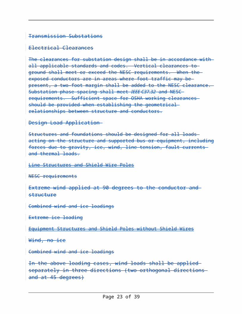
Electrical ClearancesThe clearances for substation design shall be in accordance with all applicable standards and codes. Vertical clearances to ground shall meet or exceed the NESC requirements. When the exposed conductors are in areas where foot traffic may be present, a two-foot margin shall be added to the NESC clearance. Substation phase spacing shall meet IEEE C37.32 and NESC requirements. Sufficient space for OSHA working clearances should be provided when establishing the geometrical relationships between structure and conductors.
Design Load Application Structures and foundations should be designed for all loads acting on the structure and supported bus or equipment, including forces due to gravity, ice, wind, line tension, fault currents and thermal loads.
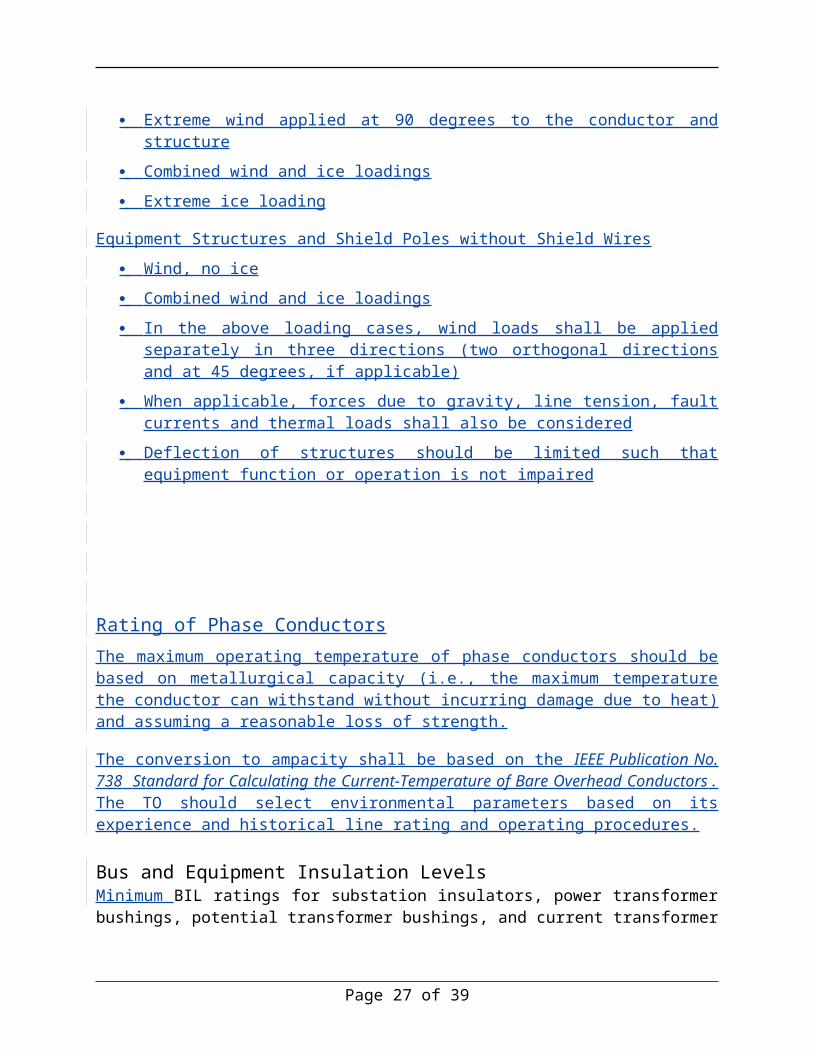
Line Structures and Shield Wire Poles
NESC requirements
Extreme wind applied at 90 degrees to the conductor and structure
Combined wind and ice loadings
Extreme ice loading
Equipment Structures and Shield Poles without Shield Wires
Wind, no ice
Combined wind and ice loadings
In the above loading cases, wind loads shall be applied separately in three directions (two orthogonal directions and at 45 degrees)
When applicable, forces due to gravity, line tension, fault currents and thermal loads shall also be considered
Deflection of structures should be limited such that equipment function or operation is not impaired
Rating of Phase ConductorsThe maximum operating temperature of phase conductors shall be based on metallurgical capacity (i.e., the maximum temperature the conductor can withstand without incurring damage due to heat) and assuming a reasonable loss of strength.
Page 17 of 28
Jay Caspary, 05/18/11,
Same as JC8. Shouldn’t we define normal, emergency, as well as short term emergency ratings for conductors using a consistent approach in SPP going forward?
Williams, Noman, 05/19/11,
Can we site a code/standard that these are based on – good but would like to see support.
Jay Caspary, 05/18/11,
Is this appropriate for all of SPP, particularly if Entergy joins us, e.g., extreme icing may not be appropriate for New Orleans?
Larry Streit, 05/20/11,
Additional clearance requirement may be required to meet utility safe working distances.
Kent M. Herzog, 05/20/11,
NESC?
Williams, Noman, 05/19/11,
Is this an internal AEP standard?
Williams, Noman, 05/19/11,
Again also need to consider RUS requirements

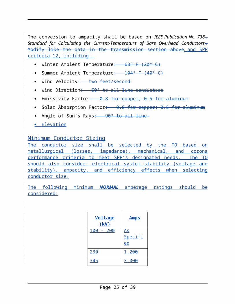
The conversion to ampacity shall be based on IEEE Publication No. 738, Standard for Calculating the Current-Temperature of Bare Overhead Conductors. Modify like the data in the transmission section above, and SPP criteria 12, including:
Winter Ambient Temperature: 68º F (20º C)
Summer Ambient Temperature: 104º F (40º C)
Wind Velocity: two feet/second
Wind Direction: 60º to all line conductors
Emissivity Factor: 0.8 for copper; 0.5 for aluminum
Solar Absorption Factor: 0.8 for copper; 0.5 for aluminum
Angle of Sun’s Rays: 90º to all line
Elevation
Minimum Conductor SizingThe conductor size shall be selected by the TO based on metallurgical (losses, impedance), mechanical, and corona performance criteria to meet SPP’s designated needs. The TO should also consider: electrical system stability (voltage and stability), ampacity, and efficiency effects when selecting conductor size.
The following minimum NORMAL amperage ratings should be considered:
Voltage (kV) Amps100 - 200 As
Specified
230 1,200
345 3,000
500 3,000
765 4,000
*NOTE:Reactive CompensationFor project cost estimates line mileage greater than 100 miles should include cost estimates for reactive compensation.
Page 18 of 28
Kevin Wray Jones, 05/23/11,
SPS uses 6 fps.
Kevin Wray Jones, 05/23/11,
SPS is using 27 degrees C.

Transmission Substations
Electrical ClearancesThe clearances for substation design shall be in accordance with all applicable standards and codes. Vertical clearances to ground shall meet or exceed the NESC requirements. When the exposed conductors are in areas where foot traffic may be present, a margin may be added to the NESC clearance. Substation phase spacing shall meet IEEE C37.32 and NESC requirements. Sufficient space for OSHA working clearances should be provided when establishing the geometrical relationships between structure and conductors.
Elevation: 1,000 feet above sea level
Design Load Application Structures and foundations should be designed per ASCE Standard No. 113, Substation Structure Design Guide, for all loads acting on the structure and supported bus or equipment, including forces due to gravity, ice, wind, line tension, fault currents and thermal loads.
Line Structures and Shield Wire Poles
NESC requirements
Extreme wind applied at 90 degrees to the conductor and structure
Combined wind and ice loadings
Extreme ice loading
Equipment Structures and Shield Poles without Shield Wires
Wind, no ice
Combined wind and ice loadings
In the above loading cases, wind loads shall be applied separately in three directions (two orthogonal directions and at 45 degrees, if applicable)
When applicable, forces due to gravity, line tension, fault currents and thermal loads shall also be considered
Deflection of structures should be limited such that equipment function or operation is not impaired
Rating of Phase Conductors
Page 19 of 28
Williams, Noman, 05/19/11,
Again should be based on SPP Criteria 12
Larry Streit, 05/20/11,
Does not coincide with SPP criteria. Winter ambient conditions may differ in different regions.
bkbrown, 05/23/11,
Same comments as above.
Kevin Wray Jones, 05/23/11,
Our elevation is 3700 feet above sea level.
The maximum operating temperature of phase conductors should be based on metallurgical capacity (i.e., the maximum temperature the conductor can withstand without incurring damage due to heat) and assuming a reasonable loss of strength.
The conversion to ampacity shall be based on the IEEE Publication No. 738 Standard for Calculating the Current-Temperature of Bare Overhead Conductors. The TO should select environmental parameters based on its experience and historical line rating and operating procedures.
Bus and Equipment Insulation LevelsMinimum BIL ratings for substation insulators, power transformer bushings, potential transformer bushings, and current transformer bushings can beare found in the tables below. When placed in areas of heavy contamination (coastal, agricultural, industrial), insulator contamination can be mitigated by using extra-creep insulators, applying special coatings to extra-creep porcelain insulators, and using polymer insulators.
Substation Insulators Add line for 115 kV
Nominal System L-L Voltage (kV)
BIL(kV Crest)
BIL (kV Crest) Heavy Contaminated Environment
115 - 138 550 650 (Extra Creep)
161 750 750 (Extra Creep)
230 900 900 (Extra Creep)
345 1050 1300 (Extra Creep)
500 1550 1800 (Standard Creep)
765 2050 2050 (Standard Creep)
Page 20 of 28
Larry Streit, 05/20/11,
Include 115 kV ???
Williams, Noman, 05/19/11,
Need to add 115-kV
Power Transformers, Potential Transformers and Current Transformers
Nominal System L-L Voltage
(kV)
Power Transformer Winding BIL (kV Crest)
PT and CT BIL (kV Crest)
Circuit Breaker BIL (kV Crest)
115 450 550 550
138 650 650 650
161 750650 750650 750650
230 825 900 900
345 1050 1300 1300
500 1550 1550/1800 1800
765 2050 2050 2050
Rating Margins for Substation EquipmentSubstation equipment shall be rated to carry the anticipated worst-case loading over a 20-year period. If actual loading forecasts are not available, then a 50% load growth may be assumed over the 20-year period, based on an annual load growth rate of 2%. Substation equipment shall also be rated for maximum short-circuit levels over the same 20-year period. If the maximum short-circuit level forecast is unknown, then a 22% increase may be assumed over the 20-year period, based on an annual growth rate of 1%..
Maximum Interrupting Fault Current LevelsThe common levels ofMinimum substation design symmetrical fault current ratings can be found in the following table. The fault current capability must exceed expected fault duty.
Voltage (kV)Interrupting Current Symmetrical (kA)
138100 – 345 40 or 63
161 40 or 63
230500 40 or 50 ??*Note: Follow up
345 40 or 50
765 50
Page 21 of 28
Williams, Noman, 05/19/11,
Need 115-kV
Larry Streit, 05/20/11,
Needs more explanation – how does this relate to max fault levels? Include 115kV?
Williams, Noman, 05/19/11,
Very specific what is the basis?
Williams, Noman, 05/19/11,
In design std the focus for the substation was 10 yrs, should timing be cosistent.
Jay Caspary, 05/20/11,
EMDE suggests “should” versus “shall” given uncertainty in long range forecasting
Larry Streit, 05/20/11,
Include 115 kV ???
Jay Caspary, 05/20/11,
EMDE uses 650 and questions need versus value of 750
Bus ConfigurationEach new substation should have an initial one-line of the substation and ultimate one-line of the substation prepared. The ultimate one-lineSubstations will be subjected to continuous revisions to accommodate future improvements. TOs will retain responsibility to ensure new substations are designed to accommodate future expansion of the transmission system, if SPP or the TO has identified that as an area of potential growth. The following table provides suggested bus configurations. Substations should be designed to accommodate the ultimate substation arrangement, including the purchase of land to accommodate the ultimate substation if SPP cost recovery is provided for that additional purchase.. *Note: Dave Parrish to revisit.
Voltage (kV) Number of Terminals Substation Arrangement230/345100 - 499
One or Two Single Bus
Three to FourSix Ring Bus
More than FourSix Breaker-and-a-half
500/765 One or Two Single Bus
Three to Four Ring Bus
More than Four Breaker-and-a-half
The following sketches show substation arrangements for breaker-and-a-half and ring bus schemes. System requirements, however, may require alternative layouts.
Depending on TO practices, a line switch may or may not be required in 345 kV breaker-and-a-half schemes or 345 kV ring bus schemes.
Page 22 of 28
Larry Streit, 05/20/11,
Many utilities use more than six unless a heavily loaded or high reliability site. Another section mentions this requirement at lower voltages.
Williams, Noman, 05/19/11,
This is not consistent with the design standards which is ring-bus then breaker and a half focused. Again need to add lower voltage 115/138/161
Minimum Rating of Terminal EquipmentMinimum terminal ratings of substation terminal equipment should be as follows:
765 4,000
Page 23 of 28
Voltage (kV) Amps100 - 200 1,200
138 & 230 2,0001,200
345 3,000
500 3,000
Jay Caspary, 05/20/11,
EMDE suggest “230 kV and below”
Williams, Noman, 05/19/11,
115-kV?
Transmission Protection and Control
Primary and Backup Protection SchemesThe following criteria shall be used to determine if one or two high speed protection systems are needed on a line. While it is possible that the minimum protective relay system and redundancy requirements outlined below could change as NERC Planning and Reliability Standards evolve it will be the responsibility of each individual TO to assess the protection systems and make any modifications that they deem necessary for transmission construction on its system.
500 / 765 kV Line ApplicationsAt least two high speed pilot schemes and dual direct transfer trip (DTT) using PLC and/or fiber are required. Fiber should be used on all new transmission lines using OPGW and PLC equipment for existing lines (Mode 1 coupling to all three phases). Where there is an underground fiber communication path OPGW is not preferred. PLC-based protection schemes using directional comparison blocking (DCB) require automatic checkback features to be installed to ensure the communication channel is working properly at all substations. *NOTE: Follow up on DCUB
345 kV Line Applications (SPS suggests this be for 300 kV and above. This is not what we would do on our 230 kV lines)Dual high speed pilot schemes and one direct transfer trip (DTT) using PLC and/or fiber are required. Dual DTT is required if remote breaker failure protection cannot be provided with relay settings. Fiber should be used on all new transmission lines using OPGW and PLC equipment for existing lines. Where there is an underground fiber communication path OPGW is not preferred. Independent PLC communication paths may be required for proper protective relay coordination. PLC-based protection schemes using directional comparison blocking (DCB) require automatic checkback features to be installed to ensure the communication channel is working properly at all substations. *NOTE: Follow up on DCUB
Below 300 kV Line ApplicationsA minimum of one high speed pilot scheme using PLC and/or fiber is required. Fiber should be used on all new transmission lines using OPGW and PLC equipment for existing lines. Where there is an underground fiber communication path OPGW is not preferred. Dual pilot schemes may be required for proper relay coordination. If dual high speed systems are needed, independent communication channels will be used. PLC-based protection schemes using directional comparison blocking (DCB) require automatic checkback features to be installed to ensure the communication channel is working properly at all substations. *NOTE: Follow up on DCUB
Page 24 of 28
*NOTE: What about substation protection?
Page 25 of 28

Scoping RequirementsThis section describes the Scoping Requirements to be used by the SPP when developing Conceptual cost estimates and the TOs when developing Study cost estimates for transmission facilities for the SPP footprint.
Conceptual Scope Requirements (Developed by SPP and provided to the TO)
Transmission Line Projects
Description of project
Termination points of each transmission line (Point A to Point B)
Voltage
Estimated Line length
Expected Performance Criteria
Need Date
Normal and Emergency limits
Substation Projects
Each substation involved in the project, including the required configuration and improvements at the remote end substations
Continuous ratings and interrupting ratings
Study Scope Requirements (Developed by the TO and provided to SPP)The Study Scope document should include the Conceptual Scope requirements in addition to the information listed below.
Transmission Line Projects
Structure type—lattice structures, poles (wood, steel, concrete, etc.)
Number of circuits
Conductor size, type and number/phase
Type of terrain
Foundation information
Switch requirements
Labor force - company crews or contract crews
Page 26 of 28
Keeler, Erin, 05/18/11,
May not be known at scope level.
Keeler, Erin, 05/18/11,
Not known at scope level.
Keeler, Erin, 05/18/11,
Many of these items are unknown at the scoping level. At this point the route may not even be defined. They probably shouldn’t be included at this point. I’ve commented on them below.
Williams, Noman, 05/19/11,
Line routing should not be a straight line point to point. Distance should be aligned along section lines i.e. run N-S / E-W
rlw0209, 05/20/11,
OG&E comments: Study Scope Requirements (Page 17 & 18) - Many of the items listed are not determined until completion of the design phase of the project and are not know at the time of the development of the scope. A sample of these items are: Labor force, number of structures, distribution / joint use requirement.
Legal requirements
Environmental study requirements
Transmission Line Projects (cont’d)
Geotechnical requirements
Survey requirements - ground and LiDAR
Special material requirements
Preliminary line route (rough location when practical)
Preliminary designo Number of structureso Structure types—dead ends, running corners, tangents
Access road requirements
Design criteria
Distribution/Joint Use requirements
Right-of-Way requirements
Right-of-Way clearing requirements
Traffic control requirements
FAA Requirements
Wetland Requirements/Mitigation
Threatened and Endangered Species Mitigation
Cultural/Historical Resource Requirements
Transmission Substation Projects
Preliminary dispatch/switching one-line diagram
All major equipment, including rehab of existing equipment to meet the SPP project scope, i.e. Transformers, Breakers, Control panels, Switches, CTs, PTs, CCVTs
BIL and wind ratings
Contamination requirements
Mobile substation requirements
Required substation property/fence expansions (indicating anticipated arrangement of proposed facilities and any resulting expansion needed)
Control house expansions (indicating anticipated panel layout and any resulting expansion needed)
Identification of parent level Design Module standards needed on the project
Page 27 of 28
Williams, Noman, 05/19/11,
What does this mean?
Keeler, Erin, 05/18/11,
What are these?
Keeler, Erin, 05/18/11,
Only provide estimated number of panels.
Williams, Noman, 05/19/11,
Not sure what this means
Williams, Noman, 05/19/11,
Some of these requirements may not be known until a project has legs; i.e. this may not be available until routing/siting has been reviewed
Keeler, Erin, 05/18/11,
All of these will not be known at scope level either but if the rest stay in the document, these should be included too.
Keeler, Erin, 05/18/11,
Not known at scope level.
Keeler, Erin, 05/18/11,
Not known at scope level.
Keeler, Erin, 05/18/11,
Fee owned or easement? We suggest that it be a requirement for 765 kV ROW to be fee owned by the T.O.
Keeler, Erin, 05/18/11,
Usually not applicable for 345 kV
Williams, Noman, 05/19/11,
Would this not need to conform to this document. We should only ask for exceptions
Keeler, Erin, 05/18/11,
Not known at scope level. Final route may not even be known.
Keeler, Erin, 05/18/11,
Not known at scope level
Keeler, Erin, 05/18/11,
Not known at scope level.
Keeler, Erin, 05/18/11,
Not all requirements may be known at scope level.
Keeler, Erin, 05/18/11,
Not all requirements may be known at scope level.

Preliminary one-line diagram
Fiber optic requirements
Remote end requirements
Any single item that would impact the cost of the associated component by > 5%
Metering requirements
Third Party requirements
Reactive Compensation requirements
Wetland/T&E/Community Approval/Unusual site prep requirements.
SCADA requirements for utilities involved
Page 28 of 28
Williams, Noman, 05/19/11,
Again this is a fair amount of specific information for a study level estimate. We are also looking for a 5% impact item on a +/- 50% estimate