INTRODUCTION 1-3 - Rotech Pumps€¦ · · 2017-03-215 pin. See Fig. 3. Do not remove bearing...
16
Installation, Operation & Maintenance Manual CX 20 SERIES
Transcript of INTRODUCTION 1-3 - Rotech Pumps€¦ · · 2017-03-215 pin. See Fig. 3. Do not remove bearing...

Installation, Operation & Maintenance Manual
CX 20 SERIES

INTRODUCTION 1-3
Installation 1
Starting Up 2-3
LUBRICATION & SERVICE 4-6
Lubrication 4
Cylinder and packing Service 4
Valve Service 4
Servicing Crankcase Parts 4
Servicing Connecting Links 5
Reconditioning Crankshaft 5
Replacing Crosshead Seals 6
SERVICE CHART 7-10
Explanation of Service Chart 7-9
Specifications 10
INDUSTRIAL PUMP PARTS LIST 11-12
WARRANTY & LIMITED LIABILITY 13
CONTENTS

1
This product and related accessories contain chemicals known
to the State of California to cause cancer, birth defects or other
reproductive harm.
Reciprocating pumps of both the plunger and piston type are
positive displacement in principle. Due to positive
displacement characteristics, problems may arise through
improper installation or application. When new or unusual
installations are planned, or the material to be pumped is a
liquid other than cold water, the customer should consult the
"Rotech Reciprocating Pump Manual" or factory for additional
information.
CAUTION: Positive Displacement Pumps must have a proper
size and operable type of pressure regulating valve or pressure
relief valve piped into the discharge line. This is mandatory to
prevent damage to pump and piping or possible injury to
personnel. Do not install any valves or shutoff devices in the
bypass line from pressure regulator to tank or supply.
CAUTION: All pumps should be installed level. For mobile
applications the maximum angle of intermittent operation
should be no more than 5 degrees in any one direction.
I - INSTALLATION (Customer Mounted Pump)
A. If possible, install suction piping one pipe size larger than
suction tapping in pump. Reduce piping size at pump with a
reducer coupling as shown on installation drawings. A
suction surge arrester, also shown, will assure smoother
operation.
B. When level of liquid supply is below that of the pump (suction
lift condition) either the bottom suction opening or both side
openings must be connected to the supply. Keep suction
piping as short and simple as possible with a minimum of lift.
Avoid any high points in suction line.
Suction piping must not have any air leaks. Check suction
piping assembly for leaks by using 20 - 80 p.s.i. air pressure and
soap bubbles or submerging assembly under water.
C. Use suction strainer and screen of adequate size to avoid
restriction of pump suction. Strainer mesh should be
sufficiently small to prevent passage of trash which may
lodge under pump valves. Keep screen clean with a regular
maintenance schedule to avoid starving of pump suction. A
starved suction condition is usually indicated by excessive
pump shock and noise. Many pump problems and most
packing or cup failures are directly traceable to a starved
suction condition.
D. When pumping liquids that are heated, reduce pump speed
to avoid suction problems. Consult “ Rotech Reciprocating
Pump Manual” or factory for temperature and speed
limitations.
E. Make sure that drive is adequate for horsepower required
and that drive is properly aligned and tensioned. With belt
drives, pulley on both motor and pump should located as
closely as possible to bearing to reduce bearing and shaft
bending loads.
Pulley Location On Pump & Motor Shaft
CAUTION: Be sure that pump belts and pulleys are properly
protected by guards according to industrial code within state of
application.
F. Make sure that all bolts, nuts, set screws and keys are
properly tightened.
G. Be sure that discharge line is properly protected by means of
a pressure regulating valve and a discharge surge arrester
INTRODUCTION

of proper size, capacity and pressure rating. The discharge
line should be of comparable size to discharge tapping in
pump. Average discharge line velocity should not exceed 5
feet per second for most satisfactory operation.
CORRECT LOCATION OF DISCHARGE SURGE ARRESTER WHEN
USING PRESSURE REGULATING VALVE
H. Nozzle capacity or demand should not exceed 90% of pump
capacity for satisfactory regulating valve operation.
Nozzling in excess of this capacity may cause unstable
pressure regulator operation.
It is also preferred to nozzle in excess of 50% of pump
capacity to reduce rate of erosion or wear on regulating valve &
seat.
When lower system demands (than rated pump capacity)
are required in an installation, the pump speed should be
reduced by changing drive ratios. This will reflect savings in
power consumption, reduce regulating valve wear and extend
pump life.
I. Where line shock or water hammer is encountered a second
surge arrester should be installed in the discharge line
adjacent tp spray gun or nozzles. Under some conditions it
may also be desirable to isolate pump from piping with a
suitable high pressure hose. This will eliminate transmission
of line vibration to the pump, with a resulting possible failure
of piping, pipe threads and/or pump casting.
J. Never pipe the bypass from a pressure regulating valve back
into pump suction. When discharge line is shut off, the
complete bypass is circulated back into pump suction with a
resulting rapid temperature rise which will destroy the
piston packing.
It is permissible to pipe the bypass from an unloader valve into
the suction because the pump pressure is unloaded when
discharge is shut off.
II - STARTING PUMP
A. BEFORE STARTING:
1. Read all instructions carefully.
2. Fill pump crankcase with recommended oil to level mark
on oil saber. Oil recommendations are covered in
lubrication section of pump instructions.
3. Replace all drain plugs in pump and piping.
2
TYPICAL INSTALLATION OF INDUSTRIAL PUMP EQUIPPED WITH PRESSURE REGULATOR VALVE

3
4. Inspect tank to be sure that no foreign material is in tank
or suction line.
5. Fill tank at least half full or connect suction to water
supply. Open valve (if present) in suction line. If pumping
from a pit, make sure that suction line is completely
submerged.
6. Make sure all valves, including spray gun or nozzles, are
open in discharge line. Spray gun may be anchored to
discharge back into tank.
7. Completely back off pressure adjusting screw on
pressure regulating valve.
CAUTION: When pumping from a pit or under a suction lift
condition, if pump does not prime in a short period, see
paragraph 1B and fill the discharge side of fluid end with water
to seal discharge valves. If pump still does not prime remove
suction hose and fill pump with water. Dry operation will cause
heating and wear on cylinders and packing. Be sure that an
operating pressure gauge is located on discharge line.
B. STARTING THE UNIT:
1. After starting, close discharge valve or gun slowly while
watching pressure gauge to make sure relief valve or
unloader is operating properly.
2. Adjust relief valve to desired pressure. See regulator
instructions.
3. Cycle nozzles or gun on and off to be sure that pressure
adjustment and regulator operation is satisfactory.
4
When replacing packing, clean all piston parts, replace and
lubricate “O” rings. Ceramic cylinders should be cleaned by
soaking in muriatic acid to remove all build-up of packing
material. Caution! Avoid direct contact with muriatic
acid. Wear protective gloves and eye protection. If
exposed, flush exposed area with water. Consult a
physician for treatment of muriatic acid burns. Clean
bore and lubricate “O” rings and cylinder with a quality water
proof grease before replacing cylinder and piston assembly. The
piston assembly should be inserted into opening. Care should
be used to assure proper seating of the cylinder into the
machined opening at the rear of the bare. With the cylinder
seated properly, and the piston assembly adjusted and locked
in place, all internal parts in place in fluid end, the fluid end can
be replaced. Care should be taken in reassembly so that large
end of suction spring (9) seats against cylinder (33) and not
between cylinder and spacer (10). Be sure to install nylon
gasket between cylinder and spacer when reassembling.
Insert all cap screws in place and pull fluid end down tight. Do
not cock fluid end while tightening, pull down evenly by
alternately tightening to final torque 25-30 ft./lbs.
VALVE SERVICE
To remove discharge valve (4) or spring (3) remove water end
and pull valve seat (6) with a 3/4-16 UNF threaded rod or cap
screw.
Suction valves will show a wear pattern on seating side but
need not be replaced unless cracked or erosion is present on
seating face. To replace valve seat (6) first clean both bores with
sandpaper or emery cloth to remove all corrosion. Replace
discharge valve and spring, “O” rings on valve seat should be
replaced and lubricated. Insert valve seat into bore, if
resistance is met as “O” rings enter bores place a flat piece of
wood on seat and tap into place with hammer.
SERVICING CRANKCASE PARTS
To remove crankshaft (16) the pistons and cylinders must first
be removed, as explained earlier. Drain oil from crankcase and
remove rear cover (14). Remove retainer ring (19) from bearing
bore. The connecting link caps should be taken off and the free
links pushed towards the water end as far as possible. BEFORE
REMOVAL, BE SURE TO NOTE THE MARKINGS ON THE
CONNECTING LINKS AND CAPS. THESE PARTS ARE NOT
INTERCHANGEABLE AND MUST BE REASSEMBLED IN
THEIR ORIGINAL POSITIONS. The crankshaft (16), bearings
(17) and bearing cap (21) can now be removed by tapping with
a hammer against a block of wood on one end of the crankshaft.
The crankshaft should be supported so that bearings leave the
LUBRICATION
Pump - Crankcase must be filled with 2 to 2 ½ pints of S.A.E. 30
oil unless ambient temperature exceeds 90°F. when S.A.E. 40
should be used. Use only quality oils with API designation MS,
SC, SD or SJ; maintain level at mark on dipstick. Foaming and
yellow discoloration of oil is an indication of water; oil should be
changed immediately to preclude possible damage to power
and components.
Note - Drain oil from crankcase after first 30 hours of operation.
It is best to always drain the oil when it is still hot. Refill with new
oil as mentioned above. Run pump at full speed under no
pressure for 2 or 3 minutes before returning to operation.
Thereafter change oil every 300 hours or immediately if water
droplets are found on dip stick. Check oil level regularly and add
oil as needed.
Avoid freezing by draining all water from pump and system in
cold weather. This can be done by breaking suction
connections, removing pipe plug from front face of pump and
turning crankshaft over 4 or 5 times, or the fluid end can be
removed to completely drain cylinders and fluid end.
SERVICE
(Caution - Disconnect electrical leads to motor or remove spark
plug leads on engine before proceeding)
CYLINDER & PACKING SERVICE
Removal: Remove 8 cap screws holding fluid end to power end
and pull straight forward. Use care with ceramic liner pumps. Do
not cock water end or drop liner. valve seat (6) valve (8) spacer
(10) and spring (9) should remain in fluid end. Loosen stem (28)
and piston assembly can be removed with a socket wrench
through cylinder opening. If cylinders have corroded in place,
they may be removed as shown in Fig. 1. Grease the O.D. when
replacing.
Figure-1
LUBRICATION AND SERVICE - CX 10 & CX 20 INDUSTRIAL PUMPS

5
pin. See Fig. 3. Do not remove bearing (17) from crankshaft (16)
unless replacement is necessary. After removing crankshaft,
the links and crosshead can be pulled out the crankcase
opening.
Figure-3
SERVICING CONNECTING LINKS
The connecting rod link is furnished with replaceable split
sleeve bearing inserts at the crank throw and a steel backed
bushing at the crosshead end. When new replacement links are
obtained, these bushings are reamed to the proper size for
immediate installation. If the bushing only is removed from an
old link, it may be necessary to ream the replaced bushing to
the proper inside diameter after it is pressed into the link. When
placing the bushing in the link be sure that the oil holes in the
bushing and link will be in line after the bushing is pressed into
position. Fig.4 shows the proper diameter to which the bushing
must be reamed for proper seating of the crosshead pin.
The connecting links should be checked for bearing wear only if
the pump shows signs which might be due to a failing link or
during a general overhaul. Unnecessary inspections may upset
smooth operation and ultimately cause failure. If it becomes
necessary to replace a link or crosshead, this can be done by
driving out the link pin (25). When replacing the pin an arbor
press should be used and care should be taken so that the link is
not bent. As the pain is pressed in occasionally the two sides of
the crosshead will give enough to grip the link so that it will not
operate freely. If this occurs, rotate the link and crosshead 180°
and rap the pin sharply in the opposite direction.
Always be sure that the proper side of the link is placed upward
when attaching it to the crankshaft. The upper side contains
three oil holes. These oil holes must be up to allow proper oil
feeding.
Figure-4
It is never practical to attempt to re-fit connecting links to the
crankshaft by filing or grinding the face of the link cap where it
contacts the link. Torque for link bolts not to exceed 65-75
inch/lbs. or 6 ft./lbs. Under normal conditions a crosshead will
not wear nor will the bore of the crankshaft wear to the extent
that oversize crossheads will be required. If extreme wear does
occur, it will be due to severe damage from the lack of oil or a
fairly large metal object scoring the crosshead bore. A
clearance of 0.002” to 0.004” is standard for the crosshead. The
parts can wear until considerably more clearance than this
exists before harmful operation will occur.
RECONDITIONING CRANKSHAFTS
When only a very small amount of damage has occurred on the
crank pins, such as small surface grooves cut part way around
the bearing surface, the crank pins can sometimes be
reconditioned for further use. This can be done with emery cloth
and polishing operation should be performed by using a very
fine emery cloth. This procedure can only be followed where the
amount of sanding does not reduce the normal diameter of the
crank pin.
If the crankshaft cannot be refinished by hand in this manner, it
will be necessary to regrind and polish the bearing surfaces for
special undersize bearings.
FIGURE - 5
Crank Pin Size “D” standard - Use Standard link Bearing
18837A100 (2 reqd. per link)
Size “D” for Reconditioned Shaft. Use undersize link
bearing 18837A20 (2 reqd. per link)
Fig. 5 shows the crankshaft with the crank pin sizes tabulated
for both standard diameter and the undersize diameter that

6
FIGURE - 7
After replacing the crossheads and links, they should be pushed
all the way forward; then the crankshaft can be replaced just as
it was removed. All link caps should be tightened in place and
free operation of the crank assured before replacing bearing
cap and retainer ring. When replacing bearing cap, an assembly
thimble as shown in Fig. 8 is helpful. The thimble should be
machined from high carbon steel and polished on the exterior to
reduce possibility of seal lip damage. Clean and lubricate all
seals and “O” rings before replacing.
FIGURE - 8
should be maintained. Worn or corroded crank pins can be
ground and polished down to 0.030” under the size when the
cranks were new. When this is done the surface should be
polished to a good smooth finish. The undersize connecting
links are made especially for turned down crankshafts. If the
crankshaft has been reground to dimension “D” for
reconditioned shafts, the undersize links can be used and will fit
properly and operate as well as the original equipment.
If the surface is badly damaged, the crankshaft can often be
salvaged by “metallizing” the crank pins and then regrinding
and polishing to the original diameter.
REPLACING CROSSHEAD SEALS
With the crankshaft and crossheads removed, the worn seals
(27) can be pried out. When installing new seals be sure to place
them with the lip facing the power end and the metal face
toward the water end. After cleaning the cavity and wiping with
oil, the seal can be pressed into place with an arbor press or by
FIGURE - 6
tapping lightly with a hammer against a block of wood. The
seals should be pressed in (27) as shown in cutaway pump view.
When returning crossheads thru new seals care should be taken
not to turn back or damage the lip of the seal. An assembly
thimble can be very helpful in this operation. Fig. 6 illustrates an
assembly thimble being placed on the end of the crosshead. Fig.
7 shows a recommended thimble for installation of oil seals.

7
A. Failure of pump to build pressure with discharge closed
B. Failure to hold pressure with discharge open
C. Pump is noisy
D. Pump gets hot
E. Pressure gauge shows abnormal fluctuation
F. Water in crankcase
POSSIBLE CAUSE OF PROBLEM F E D C B A
1. Pump not primed X
2. Valve closed in suction line X X
3. Suction line or sediment chamber clogged X X X
4. Air leaks in suction line X X X
5. Badly worn packing material X X
6. Pump cylinder cracked X
7. Nozzle hole too large X
8. Air chamber waterlogged X X
9. Need vacuum chamber in suction line X
10. Moisture or water in crankcase X
11. Worn connecting links X X
12. Foaming spray mixture X X X
13. Regulator plunger stem sticks X
14. Pressure regulator badly worn X X
15. Foreign matter under pump valve X
16. Badly worn or loose belts X X
WARNING - THIS PUMP MUST BE INSTALLED WITH A PRESSURE RELIEF VALVE IN DISCHARGE LINE
Explanation of the Service Chart
1. Pump priming is usually not necessary when the pump is
installed correctly. However, there are certain unusual
conditions which may make it necessary to prime the pump
to get the pumping action started. Priming will be required
under conditions where it is impossible for the plunger to
displace the air in the pump and replace it with water. This
could be caused by a high suction lift (high from the water
supply to the pump), the valves being stuck on the seat,
such as after pumping a sticky fluid, or it might be caused by
valves sticking due to extreme corrosion of the valves ans
seats. A pump will not prime readily if someone has
tampered with the valve springs causing them to exert
undue pressure of the valve plates against the valve seats.
When the pump appears to need priming this condition can
be checked by pouring water into the cylinder body through
one of the valve cap openings or into the pump discharge
opening at the same time operating the pump to work the
water into the cylinder and valve passages.
2. Frequently a gate valve is installed in the suction line
between a tank or pressure line and pump sediment
chamber. This valve is usually installed in the line to shut off
the supply source for cleaning sediment chamber or for
pump repairs.
If this valve is closed or even partially closed it will
interfere with the flow of water to the pump suction to such
an extent that the pump will not perform to full capacity. If
the valve is partially closed it may cause severe knocking &
vibration of the pump because the water cannot flow into
the cylinder cavities fast enough.
3. A sediment chamber should be installed in the suction line
between the gate valve and the pump suction.
The strainers in these sediment chambers are of more
than adequate capacity to allow a free flow of the liquid to
the pump. However, because of its normal function of
collecting sediment the strainer may be come severely
clogged and in some cases, it will completely stop the flow of
SERVICE CHART - TROUBLESHOOTING GUIDE
8
liquid to the pump. The length of time the pump may
operate before it is necessary to clean the strainer will
depend upon the type of liquid pumped. After the pump has
been used a short period the operator will soon become
familiar with the amount of running time between strainer
cleanings.
4. Any piston pump, when operated at high pressure sure will
not operate satisfactory or quietly if a mixture of air and
water is allowed to enter the pump suction. For this reason, a
small air leak in the suction line will cause the pump to knock
and vibrate excessively. This holds true only for a small air
leak which allows the pump to draw a certain amount of
water mixed with air on each stroke of the piston. A large air
leak will cause the pump to lose prime after which it cannot
be reprimed until the air leak is stopped. Air leaks may occur
at the joints of the suction line piping, at the gate valve in the
suction line, at the gasket sealing the cap on the sediment
chamber or by a crack in the suction wall of the cylinder
body, such as might be caused by freezing weather. There is
also a remote possibility of air drawing past the piston on the
suction stroke if the packing is badly worn.
5. Badly worn packing or valves and valves seats will cause a
serious drop in pump capacity. This will be indicated by a
drop in pressure when guns are turned on. Worn packing is
very easy to detect because of the water leakage. The
packing should be replaced just as soon as this leakage is
noticed. If it is allowed to continue some of the material may
work past the piston rod seals into the pump crankcase.
Water in the pump crankcase will cause severe corrosion of
the bearings causing them to fail. Worn valves can only be
detected by visual examination of each valve assembly. The
most prevalent cause of valve wear is the use of highly
abrasive liquids. This will cause the valve and valve seat to
wire cut. The cut starts as a very small groove but increases
very rapidly once the valve starts to leak through this
groove. Cutting will usually be much more evident on the
valve plate in flat valve pumps. If the valve plates are
replaced as soon as they start to show this cutting action it
will prevent the valve seat from becoming cut in a similar
manner and keep the cost of replacement parts to a
minimum.
6. Pump cylinder bodies must withstand an extreme amount of
shock and pulsation while the pump is in operation. If the
pump is allowed to freeze, due to not being drained, the
freezing may crack the cylinder body walls in almost any
location. If the crack should occur on the suction valve or
cylinder portion of the body it may allow a small amount of
air to enter on the suction stroke and cause noisy operation
or a decrease in pumping capacity. If the crack develops in
the walls between the cylinder cavities or discharge valve
cavity it may allow the water to flow from one cavity to the
adjacent cavity and rob the pump of its effective
displacement. This will not cause noisy operation but will
reduce the pump capacity and may show up as a drop in
pressure when the discharge is open.
7. The holes in gun or nozzle discs are continually subject to
wear because of the high velocity of the liquid through the
holes. Naturally they wear much faster if there is any
abrasive or solid material in the liquid. If the holes become
worn too much they may allow a higher rate of discharge
than the pump is able to provide and a drop in pressure will
be noticed. This can quickly be checked by reducing the
number of nozzles or guns and at the same time watching
the amount of overflow from the pressure regulator. If there
is considerable overflow, even though a drop in pressure has
been noticed, it is an indication that the regulator valve is
worn rather than the gun or nozzle discs.
8. When a pump is used for a long period of time without the
source of supply being completely exhausted so that air can
enter the pump we sometimes encounter a waterlogged air
chamber. This decreases the effectiveness of the air
chamber causing undue pulsation at the discharge. If this
should happen the suction should be open to atmosphere at
some point to allow air to be drawn through the pump to
recharge the air chamber. This should be done with the
pressure release valve open so the pump operates at no
pressure, otherwise it will not pump air into the air chamber.
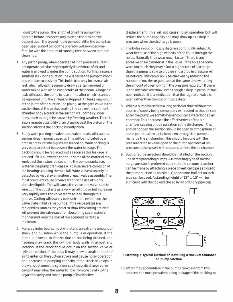
9. Suction surge arresters should be installed on the suction
line of reciprocating pumps. A rubber bag type of suction
surge arrester is preferred but a suitable vacuum chamber
can be made by attaching a piece of vertical pipe as close to
the pump suction as possible. One and one-half or two inch
pipe can be used. A standing height of 12” to 15” will be
sufficient with the top end closed by an ordinary pipe cap.
Illustrating a Typical Method of Installing a Vacuum Chamber
on pump Suction
10.Water may accumulate in the pump crankcase from two
sources; the most prevalent being leakage of the packing as
9
explained in Paragraph 5. The other means of accumulation
being a condensation of moisture inside the crankcase due
to changes in weather or the repeated heating and cooling
of the pump due to its normal usage. Pumps that are used
rather consistently and run for a considerable period of time
to heat the oil and other working parts will not normally
accumulate water by consideration. If the packing is
replaced as soon as it starts to leak it will be impossible for
water to enter the crankcase from this cause. In localities or
conditions where extremely abrasive liquids must be used, it
is always advisable to replace the cylinder shells at the same
time the worn packing is replaced. New packing will not give
satisfactory service if it is placed in a badly worn and
roughened cylinder shell.
11.Worn connecting link bearings will only develop because of
unusual or adverse operating conditions. They will,
however, be seriously affected by corrosion if water is
present in the crankcase and they will wear out from
overheating if adequate oil is not provided in the crankcase.
For this reason we recommend through draining, cleaning
and refilling with new oil prior to any storage period. Replace
bearings as soon as any damage is discovered to avoid
possible damage to crankshaft. (See Lubrication
instructions).
12.A foaming mixture will sometimes have the same effect as a
small air leak in the suction line. This is because various
quantities of the foam is drawn through the suction line into
the pump disrupting the normal flow of water.
13.Pressure regulators that are operated by plunger action may
become sluggish in action due to the plunger sticking or
fitting too tightly in its cylinder. This condition may be
caused by an accumulation of chemicals collecting in and
around the plunger, or may be due to excessive corrosion of
the plunger parts. To check this condition, remove and clean
the plunger. After cleaning the plunger, parts should be
covered with a waterproof grease before assembling.
14.In some cases there is a tendency for the pressure regulator
valves to chatter or vibrate excessively. This is an indication
of unstable operation due to nozzling in the high or low
capacity range of the regulator. On systems using pressure
regulators valves, the nozzling requirements should be at
least 50% and not exceed 90% of pump capacity.
Due to nozzle disc wear, the system requirements may
exceed the 90% limit, resulting in cycling or hammering of
the regulator. This can readily be checked by replacing the
worn discs with new discs.
15.If a large piece of foreign matter becomes lodged between a
pump valve and valve seat or if something of this kind
becomes wedged in so that it prevents the valve from
operating normally we can except drastic drop in capacity
and considerable surge or pulsation will be noticed in the
discharge line. To correct a condition of this kind it is usually
necessary to examine each valve in the pump until the
offending condition is located. The use of clean liquid and
seeing that the suction strainer is in proper condition will
prevent trouble of this kind.
16.If the V-belts have a tendency to wear rapidly, it may be due
to having the belt tightener pulley adjusted too far into the
belt, throwing a reverse bend in the belt where it passes over
the pulley. If very much reverse angle seems necessary to
keep the belt tight, other provisions should be made for
tightening, such as placing shims under the pump base or
otherwise spreading the drive centers enough to take up the
belt length. On multiple V-belt drives, a complete set of belts
should be installed when making a replacement. Further, all
the belts in one set should be checked for length and
accurately matched to avoid placing an undue load on any
one belt.

10
SPECIFICATIONS
TYPE
Rated Capacity G.P.M. @ 560 R.P.M.
Pressure Rating
Required B.H.P. @ 560 R.P.M. and Rated Press.
Temperature Rating (Max.)
Cylinder Bore
Stroke
Suction Size
Discharge
Crankshaft Dia.
Keyway
Cylinder Material
Fluid End Material
Packing Material
Valve Material
Seat Material
Piston Assembly
Approx. Ship. Wt.
Recommended Regulator
Recommended Discharge Surge Suppressor
Suggested Drive for 1750 R.P.M. Motor Drive Sheave 3V Section 3 Groove 4.5” O.D.
- Driven Sheave 3V Section 3 Groove 14” O.D. 1 1/8 Bore 1/4x1/8 K.W.
- Belts matched Sets of (3) 3V 630 (63” Outside Circumference)
- Approx. Center Distance = 16.3”
Triplex - Single Acting
180°F
1 1/4”
1 ½ N.P.T. (Bottom), 1 1/4 N.P.T. (Sides)
1” N.P.T. (Top)
1 1/8”
1/4 x 1/8
Alumina Ceramic
Ductile Iron or Aluminum Bronze
V-Ring/Buna N & Cotton Duck
Stainless Steel & Delrin
Stainless Steel
Stainless Steel
104#
CX10-15AV
10.4
1500 P.S.I.
11.2
1 1/4”
22900B
6CU
CX20-10AV
20.8
1000 P.S.I.
10.8
17527B3
12CU
1 3/4”

11
CATALOG NUMBER OF INDUSTRIAL PUMPS (w/ceramic liners)
Ref. No.
CX10-15 CX20-10
Part No.Part No.Qty.
11
1
1
19319D012
19319D013D
19319D008D
19319D012
19319D013D
19319D008D
32 20488A000 20488A000
3
4
3 18318A000 18318A000
3
3
18317A000 18317A000
18317A001 18317A001
53
3
19320A000 19320A000
19320A002 19320A002
63
3
05876A203 05876A203
05876A201 05876A201
73
6 05876A092 05876A092
05876A202 05876A202
8
9
10
3
3
3
19321A000 19321A000
19322A000 19322A000
19323A000 19323A000
11 3 05059A398 05059A398
12 3 17050A001 17050A001
133
3
05030A146 05030A147
05030A204 05030A205
14 19605A000 19605A000
Description
Body, Liquid End, w/Spring Guide
Ductile Iron
316 Stainless Steel
Cast Aluminum Bronze (AB)
Spring Guide
Spring Discharge
Valve Discharge
Valve Discharge, 316 SST
Valve Seat
Valve Seat, 316 SST
O-Ring, 15/16” I.D., 1-1/8” O.D., 3/32” Dia.
O-Ring, 15/16” I.D., 1-1/8” O.D., 3/32” Dia., 316 SST
O-Ring, 2-1/8” I.D., 2-5/16” O.D., 3/32” Dia.
O-Ring, 2-1/8” I.D., 2-5/16” O.D., 3/32” Dia., 316 SST
Valve Suction
Spring Suction
Spacer, Cylinder Liner to seat
Gasket, Nylon, 2” I.D., 2-19/64” O.D., 0.040” Dia.,
Spacer to Ceramic Liner
Cap Screw, Plunger to Plunger Stem
Washer, Cap Screw to Packing
Washer, Cap Screw to Packing, 316 SST
Spring, Spacer, Plunger
153
3
05030A141 05030A145
05030A202 05030A203
Washer, Packing, Plunger
Washer, Packing, Plunger, 316 SST
INDUSTRIAL PUMP PARTS LIST

Note: Bold type indicates "normal" wearing items or items replaced when rebuilding a reciprocating pump (typ.)
12
CATALOG NUMBER OF INDUSTRIAL PUMPS (w/ceramic liners)
Ref. No.
CX10-15 CX20-10
Part No.Part No.Qty.Description
16 3 18922A001 18922A002
17 3 19327A000 19328A000
183
3
05030A142 05030A143
05030A200 05030A201
19
3
3
1
2
19325A000 19326A000
19325A010 19326A010
05022A061 05022A061
05022A065 05022A065
20 3 19346A000 19346A001
21 3 05030A141 05030A141
3 18449B001 18449B00122
3 05030A198 05030A198
23
24
3 14383A003 14383A003
“V” Packing, for Plunger
Follower, Plunger
Washer, Plunger, Stainless Steel
Washer, Plunger, 316 SST
Stem, Plunger
Stem, Plunger, 316 SST
Plug, Drain 1/4” NPT, 316 SST
Plug, Pipe 1-1/4” NPT, Alum. Bronze
Cylinder Liner, Ceramic
Washer, Splash, 0.575” I.D., 1-13/16” O.D., 0.064” Thick
Crosshead
Washer, Splash, Nylon 1-5/8” I.D., 2-1/4” O.D., 0.040” Thick
Oil Seal, Crosshead to crankcase
Pin, Link to Crosshead 3 18448A000
18837A100K
18448A003
18837A100K
25
25A
26
27
28*
28
29
30
31
32
33
34
35
36
37
38
39
40
3
3
6
1
6
3
3
1
2
2
2
1
1
1
1
1
8
1
1
4
8
4
1
1
2
1
06106A016 06106A016
18837A100 18837A100
18837A020 18837A020
18836B000 18836B000
27877A000 27877A000
05030A092 05030A092
05876A035 05876A035
08565A011 -
- 06114A003
14383A004 14383A004
18451C002 18451C002
10848A016 10848A016
18452A000 18452A000
19314B000 19314B000
19315B000 19315B000
19100A001 19100A001
20360A010 20360A010
19313E001 19313E001
19102A014 19102A014
05454A005 05454A005
19102A015 19102A015
05022A006 05022A006
05022A009 05022A009
05022A041 05022A041
19324A000 19324A000Plunger Cover
Cap Screw, Liquid Body to Cylinder Body
Plug, Drain, 1/4” NPT
Plug, Pipe, 1/4” NPT
Plug, Pipe, 1-1/4” NPT
Cap Screw, Liquid Body to Cylinder Body
Lockwasher 7/16” (for cap screw ref. nos. 38 & 39)
Crankshaft and Cylinder Body
Oil Gauge with O-Ring 05876A074
Cap, Screw, Rear Cover to Crankcase
Cover, Rear, Crankcase
Gasket, Rear Cover to Crankcase
Cap, Bearing, for Crankshaft
Retaining Ring, Bearing Cap to Crankcase
Crankshaft
Oil Seal, Crankshaft to Crankcase
Bearing, Roller, Crankshaft
Bearing, Ball, Crankshaft
O-Ring, 3” I.D., 3-1/4” O.D., 1/8” Dia. for Bearing Cap
Sleeve Bearing, Link to Crankshaft Undersize
Sleeve Bearing, Link to Crankshaft
Cap Screw for Link
Bearing Halves, Pair
Link Complete
Bushing
Washer
13
WARRANTY & LIMITED LIABILITY
Rotech Pumps
Pumps manufactured & assembled by Rotech covered by warranty for free of manufacturing defects for a period not
exceeding twelve months from the date of shipment from our Plant/warehouse. This warranty will be limited and subject to
Rotech authorisation/approval.
Rotech will make good by repair or its option the replacement of faulty parts under warranty, providing always that:
(a) The equipment was correctly installed and properly used in accordance with Rotech Installation & Operating
instruction manual and accepted codes of good engineering practice.
(b) The claims for goods under warranty arise solely from faulty design, material or workmanship. Rotech products
don’t offer warranty or gaurantee for any pump applications. The customer can consult consuling engineers
before purchase of pumps.
(c) The repair is carried on in the Rotech service department or by an authorized agent or distributor appointed by
Rotech. Authorized repair agent must obtain written approval (WRA#) from Rotech before Completing repair
under warranty.
(d) Authorized repair agents will be refunded with the amount of equivalent to a similar repair work in the Rotech
service department.
(e) All freight costs to and from the service department or repair agents to be paid by the purchaser.
In the case of equipment or components which are not manufactured by Rotech, but supplied by Rotech.
For Example: Electric motors, engines, trade accessories etc. The warranty is limited of such equipment and subject
to respective manufacturers.
Rotech Pumps warranty doesn’t cover any of the following:
(a) Claims for third party liability, labor cost, transportation cost or damage caused by failure of any of the company’s
products.
(b) Damage caused by abnormal operating conditions, war, violence, storm, cataclysm or any other force.
(c) Damage caused by the equipment being used for an application for which it is not recommended.
(d) Damage caused by sand or abrasive materials, corrosion due to acid waters, electrolytic action, liquid
temperature beyond the recommended range, cavitation, improper supply voltage or insufficient liquid to enable
the pump to specification.
The decision of Rotech in relation to any claims or disputes over warranty is final.
This warranty is in lieu of all other warranties and conditions expressed or limited written or oral, statutory to the extent
allowable by law or otherwise, which are hereby negated and excluded.
Limited Liability
Rotech shall not be liable for any damage, delays or personal injury caused by following improper or proper procedure of
installation and maintenance of equipment being supplied by Rotech.
The pump and other equipment supplied by Rotech based on customer specification. Rotech can’t be liable the installation
of pump and equipment in any hazardous environment. Customer has to consult engineers before purchasing for proper
pump application.

1320 Britannia Road East
Mississauga, Ontario, Canada. L4W 1C8
Phone: (905) 461-9617 | Fax: (905) 461-9618
Toll Free: 1-866-217-PUMP (7867)
Email: [email protected] | www.rotechpumps.com