INTRODUCING FILE AREA NETWORKS - SNIA · SAN Architect at Brocade, which means that he was one of...
220
INTRODUCING FILE AREA NETWORKS FIRST EDITION Your first look at FAN technology MICHAEL O’CONNOR & JOSH JUDD
-
Upload
truongcong -
Category
Documents
-
view
216 -
download
0
Transcript of INTRODUCING FILE AREA NETWORKS - SNIA · SAN Architect at Brocade, which means that he was one of...

INTRODUCING
FILE AREANETWORKSFIRST EDITION
Your first look at FAN technology
MICHAEL O’CONNOR & JOSH JUDD
Copyright © 2007 Brocade® All rights reserved.
Brocade and the Brocade B-wing symbol are registered trademarks of Brocade Communications Systems, Inc., in the United States and other countries. All other brands, products, or service names are or may be trademarks or service marks of, and are used to identify, products or services of their respective owners.
No part of this book shall be reproduced or transmitted in any form or by any means, electronic, mechanical, magnetic, photographic including photocopying, recording or by any information storage and retrieval system, without express prior written permission from Brocade. No patent liability is assumed with respect to the use of the information contained herein. Although every precaution has been taken in the preparation of this book, the publisher, the author, and Brocade assume no responsibility for errors or omissions. Neither is any liability assumed for damages resulting from the use of the information contained herein. This material is subject to change without notice.
Brocade Bookshelf TM Series designed by Josh Judd
Introducing File Area Networks
Written by Michael O’Connor and Josh Judd Edited by Victoria Thomas, Kent Hanson, and Josh JuddDesign and Production by Victoria ThomasIllustrations by David Lehmann
Printing HistoryAdvance Edition in March 2007First Edition in May 2007
Published by:
1094 New Dehaven St.West Conshohocken, PA 19428
www.InfinityPublishing.comwww.BuyBooksOnTheWeb.com
Toll-free: (877) BUY-BOOKLocal Phone: (610) 941-9999Fax: (610) 941-9959
ii Introducing File Area Networks

Important Notice
Use of this book constitutes consent to the following conditions. This book is supplied “AS IS” for informational purposes only, without warranty of any kind, expressed or implied, concerning any equipment, equipment feature, or service offered or to be offered by Brocade. Brocade reserves the right to make changes to this book at any time, without notice, and assumes no responsibility for its use. This informational document describes features that may not be currently available. Contact a Brocade sales office for information on feature and product availability. Export of technical data contained in this book may require an export license from the United States government.
Brocade Corporate HeadquartersSan Jose, CA USAT: (408) 333 [email protected]
Brocade European HeadquartersGeneva, SwitzerlandT: +41 22 799 56 [email protected]
Brocade Asia Pacific HeadquartersSingaporeT: +65 6538 [email protected]
Acknowledgements
Special thanks are due to Mike Klayko and Tom Buiocchi for executive-level support.
Concepts, diagrams, and chunks of text were adapted from slides, manuals, brochures, and white papers prepared by Brocade Education, Technical Support, Professional Services, Engineering, and Marketing. Content was also adapted from the books “Principles of SAN Design” and “Multiprotocol Routing for SANs” by Josh Judd. (Both of these are available from “Buy Books On The Web,”www.bbotw.com, and from most other major retail book outlets.) Content was adapted from documentation originally produced by the Brocade Houston team and other Brocade application product teams. In particular, Rahul Mehta and his team provided many pages of source content, including diagrams, text, and lists of key concepts.
This book would not have been possible without reviews from Kent Hanson, Victoria Thomas, Mike Schmitt, and Martin Skagen.
Finally, the authors would like to acknowledge the hard work of the Brocade Engineering teams, without whom there would be no need for a book on FAN technology, as there would be no products about which to write.
Introducing File Area Networks iii

About the Authors
Michael O’Connor is a Senior Technical Marketing Engineer in Brocade Technical Marketing. In addition to writing about best practices, he works on future technologies and proofs-of-concept as well as putting out fires. He also works with SEs and end-users world wide.
Before working at Brocade, Mike spent ten years at Sun Microsystems in the network storage group. He also has many technical certifications, and a couple of advanced college degrees. If you ever go to his “cave”, you will see that he has his own ISP setup right next to the TV.
To Mom, Jordan, Croft, Miss B. and Tuhan
Josh Judd is a Principal Engineer in Brocade Technical Marketing. In addition to writing, he provides support for roadmap activities, develops new product requirements, and works directly with systems engineers, OEM partners and end users worldwide.
When he first went to work for Brocade, Josh was the company’s senior IT technical resource, responsible for the architectural design of all network, server, and desktop infrastructure worldwide and escalations. His previous experience, degree, and certifications are IT-related. He was the first Senior SAN Architect at Brocade, which means that he was one of the first full-time professional Fibre Channel (FC) SAN designers in the world.
About the Book
This book contains information about File Area Networks (FANs) in general, and specific information about FANs built with Brocade products. It is also designed to be useful as a desktop reference for FAN administrators. Information from many white papers, classes, and the authors’ experience has been combined to create this work.
This book is appropriate for:• Administrators responsible for or deploying FANs• Systems Engineers who design and deploy FANs• OEM personnel involved in selling or supporting FANs• Analysts needing an understanding of the FAN market• Network Engineers wishing to expand their skills
We welcome your comments on this book. Send feedback to [email protected] and include the book title, edition, and publication date. If applicable, include the page number and paragraph to which each comment applies.
iv Introducing File Area Networks
Introducing File Area Networks
Contents
Chapter 1: FAN Basics ...............................................................................1File Area Networks ................................................................................................1FAN Drivers ............................................................................................................4FAN vs. SAN ...........................................................................................................5FAN Support Products ..........................................................................................6
Underlying Network Components ................................................................7RAID Arrays ....................................................................................................8
FAN Protocols ........................................................................................................9IP and Ethernet ...........................................................................................10Network File Systems .................................................................................10
Chapter Summary ...............................................................................................13
Chapter 2: FAN Solutions ....................................................................... 15Storage Consolidation ........................................................................................16Namespace Globalization ..................................................................................18Data Migration ....................................................................................................22Disaster Recover/Business Continuance .........................................................24WAN Performance Optimization ........................................................................27Chapter Summary ...............................................................................................29
Chapter 3: Building Blocks ..................................................................... 31Brocade StorageX ...............................................................................................31Brocade WAFS ....................................................................................................35Brocade FLM .......................................................................................................38Brocade MyView .................................................................................................40Brocade UNCUpdate ...........................................................................................41Brocade Unified FAN Strategy ............................................................................42Customer Case Studies ......................................................................................43
StorageX for Data Replication and Protection ..........................................43StorageX and WAFS Working Together ......................................................45
Chapter Summary ...............................................................................................46
v
Contents
Chapter 4: Design Considerations ........................................................ 47Compatibility .......................................................................................................48Network Topologies ............................................................................................50
Topology Names ..........................................................................................50Overlay Networks ........................................................................................51
Reliability, Availability, and Serviceability ..........................................................52Reliability .....................................................................................................52Availability ...................................................................................................54Serviceability ...............................................................................................60
Performance .......................................................................................................61Scalability ............................................................................................................62Total Solution Cost ..............................................................................................63WAN .....................................................................................................................63
General Distance Considerations ..............................................................64Data Migration Considerations ..................................................................65Disaster Recovery Considerations .............................................................65
Implementation and Beyond ..............................................................................66Rack Locations and Mounting ...................................................................66Power and UPSs ..........................................................................................68Staging and Validation ...............................................................................68Release to Production ................................................................................69Day-to-Day Management ............................................................................70
Planning for Troubleshooting .............................................................................70Chapter Summary ...............................................................................................71
Chapter 5: Brocade StorageX ................................................................ 73Deployment Examples ........................................................................................75
Single User Drive Mapping Proliferation ...................................................75Multi-Department Drive Mapping Inconsistency ......................................77Drive Mapping and Communications ........................................................78Infrastructure Changes ..............................................................................79Storage Optimization ..................................................................................79Data Lifecycle Management ......................................................................81
Product Architecture ...........................................................................................82Client/Server Design ..................................................................................83GNS Deployment ........................................................................................84Replication Technology ...............................................................................87
Data Migration Tasks ..........................................................................................98Data Migration Methods ....................................................................................99
Migrations Procedures with Unchanging Structures ................................99Migrations Procedures with Changing Structures ..................................101Migrations Procedures with Server Consolidations .............................. 102
StorageX and NetApp Storage Device Integration ......................................... 104NetApp Filer in the Physical View tree .................................................... 104NetApp vFiler in the Physical View tree .................................................. 104
vi Introducing File Area Networks
Contents
Troubleshooting ............................................................................................... 109Installation Problems ............................................................................... 109Namespace Problems ............................................................................. 110Replication Problems .............................................................................. 110
Chapter Summary ............................................................................................ 111
Chapter 6: Brocade WAFS ....................................................................113WAFS Business Case ....................................................................................... 114Challenges to Centralization ........................................................................... 115
WAN Latency and Protocol Design ......................................................... 115Lack of Bandwidth ................................................................................... 115Lack of Data Integrity .............................................................................. 115Residual Branch Office Servers .............................................................. 116Summary: Workarounds Don’t Work ...................................................... 116
Brocade WAFS Architecture .............................................................................117Node Types ................................................................................................117Core Technology ....................................................................................... 118Performance Architecture and Benefits ................................................. 120
Availability and Integrity Benefits ................................................................... 122End-to-End Security ................................................................................. 122Full CIFS Disconnection Support ............................................................ 123
Other Architectural Benefits ............................................................................ 125Single Instance Storage .......................................................................... 125Transparent Pre-Population .................................................................... 125
Edge Office IT Services .................................................................................... 125Print Services ........................................................................................... 126Domain Controller Services .................................................................... 126Network Services ..................................................................................... 127Web Caching Services ............................................................................. 127Management Services ............................................................................ 127
Protocol Acceleration ....................................................................................... 128TCP Acceleration ...................................................................................... 128WAFS Transport Protocol Acceleration ....................................................131
Data Reduction ................................................................................................ 133Data Compression ................................................................................... 134Application-Aware Data Reduction ......................................................... 135
Deploying WAFS ................................................................................................137At the Data Center ....................................................................................137At the Branch Office .................................................................................137High Availability Deployments ................................................................. 140Flexible Platform Options .........................................................................141Platform Hardware ................................................................................... 143
Chapter Summary ............................................................................................ 144
Introducing File Area Networks vii

Contents
Chapter 7: Brocade MyView .................................................................145System Requirements ..................................................................................... 148
MyView Server and Client Requirements ............................................... 148MyView Database Requirements ............................................................ 148MyView Disk Space Requirements ......................................................... 148
Namespace Design Considerations ............................................................... 149Reduce Complexity .................................................................................. 149Consider Reliability .................................................................................. 149Cascaded Namespaces .......................................................................... 149DFS Namespace Sizing ............................................................................151
Namespace Implementation ...........................................................................151Chapter Summary ............................................................................................ 152
Chapter 8: Brocade FLM .......................................................................153Effect of Deploying FLM .................................................................................. 155FLM In Action ................................................................................................... 155FLM Policies ..................................................................................................... 158FLM and Backups ............................................................................................ 159FLM Deployment Tips and Tricks .....................................................................161
When to Deploy FLM ................................................................................161General Tips ............................................................................................. 162Performance and Scalability Tips ........................................................... 163Setting the Offline Attribute .................................................................... 166Auto-Remigration and Auto-Exclusion .................................................... 166Security Tips ............................................................................................. 167Implementation and Management ........................................................ 167Data Availability and Recovery ................................................................175Communicating with Users Before Rollout ............................................ 181
Chapter Summary ............................................................................................ 182
Chapter 9: Brocade UNCUpdate ..........................................................183System Requirements ..................................................................................... 184How It Works .................................................................................................... 184Deploying UNCUpdate ..................................................................................... 185
Command-Line Interface ........................................................................ 185The Desktop ............................................................................................. 185Search and Modify Modes ...................................................................... 186The Directives File ................................................................................... 186Templates ................................................................................................. 188Reports ..................................................................................................... 188Important Notes ....................................................................................... 189
Troubleshooting ............................................................................................... 189Chapter Summary ............................................................................................ 190
viii Introducing File Area Networks

Contents
Appendix A: Reference .........................................................................191Ethernet and IP Network Equipment .............................................................. 191Ethernet L2 Edge Switches and Hubs ............................................................ 191
IP WAN Routers ........................................................................................ 191Storage Equipment .......................................................................................... 192
RAID Arrays ............................................................................................... 192
Appendix B: Namespace Requirements ............................................195
Appendix C: WAFS Sizing Guidelines ..................................................197Supported TPA Connections with WAFS 3.4 ...................................................197
Core Node .................................................................................................197Edge Node .................................................................................................197
WAFS Sizing Guidelines for CIFS ..................................................................... 198Core Node ................................................................................................ 198Edge Node ................................................................................................ 198WAN Throughput ...................................................................................... 198
Glossary .................................................................................................. 199
Introducing File Area Networks ix

Contents
x Introducing File Area Networks

Introducing File Area Networks
Figures
Figure 1. High-level view of a FAN ......................................................................3Figure 2. FAN and SAN architectures in concert ...............................................6Figure 3. White space utilization in a DAS environment .................................16Figure 4. Network file-system mapping ...........................................................19Figure 5. Global namespace .............................................................................20Figure 6. Multi-site GNS Scenario ....................................................................21Figure 7. DR failover using a FAN overview .....................................................25Figure 8. DR failover using a FAN (detailed) ....................................................26Figure 9. High-level WAFS architecture ............................................................29Figure 10. Brocade WAFS Appliance ................................................................35Figure 11. Brocade Unified FAN Strategy ........................................................43Figure 12. Acme’s file data replication and protection strategy ....................44Figure 13. ABC’s enterprise data consolidation and protection strategy ......46Figure 14. Horizontal redundant relationships ...............................................57Figure 15. Bad rack implementation (airflow problem) ..................................67Figure 16. Too many drive mappings ...............................................................75Figure 17. Drive mappings consolidated .........................................................76Figure 18. Inconsistent mappings ....................................................................77Figure 19. Inconsistent mappings and communications ..............................78Figure 20. Migrating to higher-capacity storage ..............................................79Figure 21. Optimizing capacity utilization with StorageX ................................80Figure 22. Data lifecycle management concept .............................................81Figure 23. StorageX applications .....................................................................82Figure 24. Client/server architecture ...............................................................83Figure 25. Namespace Creation Wizard ..........................................................85Figure 26. StorageX administration console ...................................................86Figure 27. Creating a DFS structure .................................................................87Figure 28. Replication technologies .................................................................88Figure 29. Replication engine locations ..........................................................89Figure 30. Data integrity options for replication ..............................................90Figure 31. BFDR methodology ..........................................................................91Figure 32. Heterogeneous replication .............................................................92Figure 33. Managing replication ......................................................................93Figure 34. Deleting orphans .............................................................................97Figure 35. Categories of migration: change or no change .............................99
ix

Figures
Figure 36. Example of changing structure migration ................................... 101Figure 37. Migration using consolidation root .............................................. 103Figure 38. Configuring filer management in StorageX ................................. 105Figure 39. Configuring volumes on a filer ..................................................... 106Figure 40. Snapshot schedule initiated from StorageX ............................... 107Figure 41. Snapshot scheduling properties and NetApp filer scheduling .. 108Figure 42. WAFS product architecture .......................................................... 117Figure 43. Exemplary WAFS deployment ...................................................... 119Figure 44. Write-back file locking architecture ............................................. 121Figure 45. WAFS security advantages .......................................................... 123Figure 46. Using WAFS to consolidate services in a branch office ............. 126Figure 47. TCP performance in a LAN vs. a WAN ......................................... 129Figure 48. TCP protocol acceleration impact on applications ..................... 130Figure 49. CIFS over a WAN without acceleration ........................................ 132Figure 50. CIFS over a WAN with acceleration ............................................. 132Figure 51. Impact of acceleration on file save time ..................................... 133Figure 52. Dictionary Compression ............................................................... 135Figure 53. Mapping Drives with WAFS .......................................................... 138Figure 54. WAFS plus WCCP Redirection ...................................................... 139Figure 55. MyView Desktop ........................................................................... 147Figure 56. Inactive vs. active data ................................................................ 154Figure 57. Impact on file storage utilization of deploying Brocade FLM .... 155Figure 58. How FLM works ............................................................................ 156Figure 59. User view of relocated files .......................................................... 157Figure 60. FLM Policy Engine ........................................................................ 158Figure 61. FLM impact on backups ............................................................... 159Figure 62. Brocade UNCUpdate client, Configuration tab ........................... 185Figure 63. Tasman Networks WAN Router ................................................... 192Figure 64. Foundry Networks Modular Router ............................................. 192
x Introducing File Area Networks
Introducing File Area Networks
1
FAN BasicsThis chapter covers some of the basics upon which the remainder ofthe book is built. This includes a discussion of what File Area Networks(FANs) are, why they are beneficial, and some of the protocols andproducts that can be used to create the underlying FAN infrastructure.For readers who are familiar with these concepts, this chapter pro-vides an review. and includes the following:
• “File Area Networks” on page 1
• “FAN Drivers” on page 4
• “FAN vs. SAN” on page 5
• “FAN Support Products” on page 6
• “FAN Protocols” on page 9
• “Chapter Summary” on page 13
File Area NetworksA large and growing percentage of corporate data takes the form offiles. This includes unstructured data organized within a file system.File data is generally different from “raw” block data, which might beused for a back-end database on a business system or enterprise e-mail server.
All file data is ultimately stored as block data on the other side of a filesystem, whether it is located on a PC, a server, or a Network-AttachedStorage (NAS) appliance. All files are blocks, although not all blocksare files. The key differentiator is that file data is accessed as a file bythe end user—such as text documents or slide presentations. Blockdata is accessed as “raw” blocks, generally by an application such as adatabase, and not by an end user.
1

Chapter 1: FAN Basics
Given the growth in the number of files that IT departments need tomanage, the increasing complexity of file systems, and the large-scaleapplications that use files, it is clear why file management has gainedprominence. This is especially true when implementing application-level disaster recovery and Information Lifecycle Management (ILM).Such initiatives have created the need for a new type of file manage-ment: the File Area Network.
The FAN concept requires an increasingly sophisticated suite of filemanagement technologies, including file-level descriptions and classi-fication to attach policies to file data. To address this need, theindustry is developing a wide range of products and services that helpstreamline the management of file-based data as part of an enterpriseFAN. This book focuses on the FAN products offered by Brocade Com-munications Systems, Inc.
The network portion of a FAN is the pre-existing corporate IP network.In addition, a FAN makes use of one or more upper-layer network filesystem protocols such as the Network File System (NFS) and the Com-mon Internet File System (CIFS). The FAN, however, is distinguishedfrom the underlying network that transports it: the term “FAN” is a logi-cal way to describe a holistic approach to implementing file-baseddata connectivity, storage, and management. This is similar to otherlayered network models. For example, storage networking traffic cantraverse Fibre Channel (FC) fabrics, Dense Wavelength Division Multi-plexing (DWDM) Metropolitan Area Networks (MANs), and IP Wide AreaNetworks (WANs); yet the Storage Area Network (SAN) is still the SANeven when it sits on top of something else.
The goal of a FAN is to provide a more flexible and intelligent set ofmethods and tools to move and manage file data in the most cost-effective and controlled manner. To accomplish this, FANs provide sev-eral key functions:
• Enterprise-wide control of file information, including the manage-ment of file attributes
• The ability to establish file visibility and access rights regardless ofphysical device or location
• Non-disruptive, transparent movement of file data across plat-forms and/or geographical boundaries
2 Introducing File Area Networks

File Area Networks
• The consolidation of redundant file resources and managementtasks
• The ability to support file data management in both data centersand branch offices
A high-level view of a FAN is illustrated in Figure 1.
Figure 1. High-level view of a FAN
The key to this architecture is that the FAN provides “coalescence”between files stored in different locations and file consumers (clients).In current data centers, separate storage devices are truly separate,which is why administrators typically spend so much time mappingdrive letters and handling complex change control processes duringmigrations. The coalescence principle means that a FAN groups sepa-rate components into one united file space. There are a number ofadministration objectives that are facilitated by this:
• Make file location and movement transparent
• Centralize file storage and management for efficiency
• Reduce the cost of remote data backup
• Intelligently migrate files based on policies
• Consolidate branch office IT infrastructure
• Comply with regulations and corporate objectives
Introducing File Area Networks 3
Chapter 1: FAN Basics
To meet these objectives, many products and services operate in theFAN, such as a namespace unifier, file routing engines, metadata man-agement, and remote office performance optimizers. This bookdiscusses those products and services, how they work, and how bestto deploy them.
FAN DriversBefore discussing how FAN technology works, it is useful to under-stand why FAN technology is needed. As the amount of file data in theenterprise grows exponentially year over year, as it has over the pastfew years, the need for file networking also increases to meet the fol-lowing challenges.
Storage Management. Where does data reside? How does it getmoved? How do people find it after it gets moved? With data spreadacross potentially hundreds of locations in an enterprise, how do ITdepartments manage drive letter mappings? These and other issuesadd an enormous amount of complexity to managing a storage envi-ronment. Administrators need to decide how to automate and usepolices to manage storage infrastructure, and ideally find a way tomanage Direct-Attached Storage (DAS), NAS, SAN, and the files storedon those devices from a single location.
Storage Consolidation. It is desirable to consolidate many scatteredstorage resources into fewer centralized locations. Indeed, sharedstorage will have an increasingly important role in driving next-genera-tion efficiencies across the enterprise to simplify management andoptimize white space—the portion of a given disk that is not used forstoring data. A very large portion of the data being consolidated con-sists of files, so an optimal consolidation solution must be intelligentat the file level.
Business Continuity/Disaster Recovery. More and more organizationsare preparing for disasters, in many cases driven by laws and regula-tions, and in other cases by fiduciary duty to investors. One goal ofsolutions in this category is to minimize client downtime during an out-age, but in all cases it is necessary to ensure the availability ofmission-critical data. Given that much, if not most, of the data beingprotected consists of files, this is a natural fit for FAN technology.
Storage Performance Optimization. When too many users access asingle device, performance degradation inevitably results. To solve theproblem, it is desirable to load balance across multiple storage
4 Introducing File Area Networks

FAN vs. SAN
devices. However, this can be tricky and time consuming to accomplishwithout automation, and doing it at all requires knowledge of fileaccess patterns.
Data Lifecycle Management. Data Lifecycle Management (DLM)requires a method for creating storage tiers and aligning archival poli-cies with regulatory compliance requirements. Additional issuesinclude how to streamline the backup process and how to optimize theuse of high-end storage subsystems. Since: most of the data beingmanaged consists of files, most of the knowledge about which bits ofdata need to “live” on what storage subsystems can be obtained onlyby looking at file-level properties. Merely looking at data blocks on araw device will not help.
Remote Site Support. Managing remote site primary storage andbackup can be a full time role. Traditional methods of centralizingmanagement of highly distributed data can be equally problematic, forexample, in terms of performance and availability. File-level tools areneeded to centralize data for ease of management, while maintainingperformance and file availability for remote users.
Data Classification and Reporting. Knowledge is power. Discoveringstorage capacity utilization and determining the business value of datais necessary in order to make good decisions about where to put data,how to protect it, and what kinds of new storage devices to purchase.As in other areas, most of the knowledge needed to classify data andmost of the information needed in reports are related to the file-levelproperties of the data.
FAN vs. SANThis section illustrates some of the reasons why it is necessary forstorage managers to move up the protocol stack all the way to the filelevel. It also explains the source of a common misconception: that FileArea Networks are a technology in opposition to Storage AreaNetworks.
In reality, the two technologies are more than complementary; they areactually symbiotic. SANs are a requirement for the most robust FANsolutions, and FAN solutions consist of tools that SANs simply cannotprovide. The fact that FANs make management easier at the file levelallows for continued growth in data on the underlying storage sub-systems … which are usually SAN attached. It is important toremember this: all file data is ultimately stored in block format, andblock data is optimally stored on a SAN.
Introducing File Area Networks 5

Chapter 1: FAN Basics
Figure 2. FAN and SAN architectures in concert
FAN Support ProductsFAN technology sits on top of other network infrastructure. Broadlyspeaking, there are seven major components to a FAN solution. Referto Figure 2 while reading this list and notice where each element sitsin the diagram:
• Clients that access files
• Connectivity between clients and the file servers, which alsoallows clients to access namespace services
• Policy-driven file management and control, to align file locationsand properties with business requirements
• A namespace, with associated software and hardware to serveand maintain it
• Devices to serve files, for example, NAS heads and file servers
• File systems residing on these servers
• Back-end storage devices, with an optional SAN
Each of these elements requires underlying support technology. Thissection discusses some of those technologies. Many comprehensivebooks have already been written about networking, and most readersare already familiar with networking products. Therefore this sectionprovides only a brief review and discussion of how these productsrelate to FAN architecture specifically.
6 Introducing File Area Networks
FAN Support Products
Underlying Network ComponentsA network hub or switch allows connectivity between its ports suchthat any port can “talk” to any or all of the other ports. Switches andhubs are both “Layer 2” devices (L2) in IP terminology. For example, inan IP/Ethernet network, switches operate at the Ethernet layer, whichis the second layer in the Internet Protocol layered model.
Switches are distinguished from hubs such that switches do not havea “shared bandwidth” architecture. In a hub configuration, if two portsare talking to each other, it precludes other ports from talking at thesame time. There is only one port of bandwidth, which is sharedbetween all nodes. If a pair of devices talk full speed to each other ona hub, other devices can be precluded from talking at all until they arefinished. On the other hand, connectivity on a switch is allowed regard-less of activity between any unrelated pair of ports. It should not bepossible for one I/O pattern on a switch to “starve” another for band-width. This is one reason why Fibre Channel switches were successfulin the SAN marketplace and FC-AL hubs quickly became obsolete: it isunacceptable for a host to be denied access to its storage for anylength of time, and this happens more often than not with hubs.
A router is similar to a switch in that it provides potential data pathsbetween all of its ports, but a router operates at a higher layer in theprotocol stack. If the switch operates at the Ethernet layer (L2), then arouter operates at the IP layer (L3). This allows a router to connectautonomous or semi-autonomous network segments together in ahierarchical structure, rather than a flat one.
Historically, routers were much slower than switches and were notavailable for high-performance applications. In fact, many IP routerswere implemented in software rather than hardware. Modern IP net-works generally use Layer 3 switches, which combine the hardware-accelerated speed of Layer 2 switching with the intelligence of Layer 3routing in a single integrated platform.
In a SAN, the reliability and performance requirements for switchesand routers are strict. The network is expected to deliver every framewithout fail or delay except under rare and extreme circumstances,and to deliver all frames in order under virtually every condition. This isbecause the nodes and applications attached to a SAN were designedfor direct attachment, where delay, out-of-order delivery, and frameloss simply do not occur. Any working SAN must make storage look asif it were directly attached from the point of view of each host, so thatthe Small Computer Systems Interface (SCSI) protocol layer can workexactly the same way for SAN as it does for directly attached storage
Introducing File Area Networks 7
Chapter 1: FAN Basics
devices. As a result, hubs are almost never suitable for SAN use, andthe vast majority of production SANs use Fibre Channel fabrics ratherthan IP/Ethernet. For production SANs, the breakdown at the time ofthis writing is more than 99% FC versus less than 1% IP.
In contrast, network file system protocols such as NFS and CIFS weredesigned with the assumption that the network could drop perhaps 1%of packets on a regular basis—since IP networks often did that untilvery recently—and are still far less reliable than FC fabrics. In addition,the protocol designers assumed that performance on IP networkswould be erratic and low compared to direct-attached storage, again,because IP networks behaved that way when the protocols weredesigned. With upper-level protocols architected to compensate forunreliable and slow underlying infrastructure, the requirements fortransport are comparatively relaxed. It is therefore not surprising thatthe protocol of choice for FAN transport is IP, usually over Ethernet.Indeed, FANs are almost always built on top of the existing commodityEthernet gear already in place in an enterprise, rather than theswitches and routers built for block storage requirements. The break-down of Ethernet versus FC deployments for network file systems isexactly the opposite of the breakdown for block-level storage networks.
The conclusion of this discussion is that most FAN deployments willmake use of IP/Ethernet gear. The network storage devices on the FANwill always have a block-level back-end, which will often be connectedvia a SAN. In that case, the back-end will almost always be FibreChannel.
RAID ArraysRedundant Array of Independent Disk (RAID) subsystems have a set ofphysical disks, which are “hidden” behind one or more RAID controllerinterfaces. The controllers present hosts with logical volumes that donot need to map directly to the physical disks. That is, the “picture” ofthe storage looks different to a host versus the disks which are physi-cally present in the RAID array. They group together physical disks toform logical volumes. This can be as simple as concatenating diskstogether so that many small disks appear to be few large volumes, orcan involve complex layouts with redundancy and performanceenhancements.
RAID arrays form the bulk of mass storage for the back-end of FANsolutions due to their high degree of configurability, enterprise classperformance, and high availability options.
8 Introducing File Area Networks
FAN Protocols
RAID arrays are block devices. In a FAN, a RAID array must have somesort of network storage front-end processor: a device that takes theraw block-level data on the RAID volumes, configures it as a “cooked”file system, and presents that file system to a network interface usinga protocol such as NFS or CIFS. This could be a general purpose serverrunning a protocol stack, or special purpose appliance hardware. Insome cases, a RAID array will be built into the same platform as thenetwork storage processor. In larger-scale solutions, RAID arrays andseparate network storage processor nodes will be co-located on aFibre Channel SAN, which will provide block-level any-to-any connectiv-ity between the processors and arrays. This solution offers the best ofboth the block and file networking architectures, and is expected to bethe norm for enterprise-class FAN deployments. See Figure 2 onpage 6 for an example.
Of course, any storage device could be used on the back-end of a FAN.This includes S-ATA drives inside servers, JBODs, tapes, solid statemedia, and so forth. A detailed discussion of storage technology isbeyond the scope of this work. See the book “Principals of SANDesign” for more information on this topic.
FAN ProtocolsThe products discussed in the previous section rely on a protocol, orrather on several protocols in combination. FAN designers must befamiliar with the characteristics of each protocol option when selectingequipment and planning for performance, availability, reliability, andfuture extensibility.
Protocols are behaviors that computers and network devices must fol-low in order to communicate. If devices on a network do not use thesame protocols, they cannot communicate. Imagine a person whospeaks only English trying to have a complex philosophical debate withanother person who speaks only Swahili. Indeed, it is often hardenough to have a conversation if one person speaks American Englishand the other learned English in the UK. Or Spanish spoken in Mexicoversus Spain spoken in Europe. Similarly, network devices must speakthe same language (for example, English) and use the same unofficialvariations (for example, American English). This means that industry-wide agreement is required on both “official” standards, and “defacto” standard implementation details.
Protocols apply at all levels of communication, from physical mediaand cabling all the way up to the application level. Many protocols atmany levels are usually involved when two devices communicate. The
Introducing File Area Networks 9

Chapter 1: FAN Basics
entire group of protocols is collectively referred to as a “protocolstack”. Every piece of the stack must work properly for communicationto occur.
This section discusses some of the protocols that are relevant to filenetworking today, focusing on networking protocols such as IP, Ether-net, Fibre Channel, NFS, and CIFS. The discussion starts at the lowestlevel of the FAN stack and then works its way upwards.
IP and EthernetInternet Protocol (IP) is the standard for communication on the Inter-net and the de facto standard in corporate LANs for applications suchas e-mail and desktop Web servers. It is also the protocol of choice forthe front-end component of file networks.
In most Local Area Networks (LANs), IP is carried over Ethernet. Upper-level protocols such as NFS and CIFS are mapped on top of IP, usuallywith Transmission Control Protocol (TCP) in between for error detec-tion. An IPv4 address consists of four bytes, usually represented indecimal format and separated by dots. For example, “192.168.1.1” isa standard format IP address.
There are advantages to IP when it is used in the way its designersintended. For example, IP was designed to support very large, widelydistributed, loosely coupled solutions such as the Internet, and istherefore optimized to solve this type of design problem. The specifica-tions for IP mandated a loose coupling between IP subnets as themost important design criteria. A given connection was consideredexpendable as long as the overall network remained online. FibreChannel, in contrast, was designed with support for high-performance,mission-critical storage subsystems as the most important factor. Itdid not need to be as scalable but it did need to be extremely fast andreliable compared to IP. Since upper-layer FAN protocols weredesigned to use IP as a transport, the reliability and performanceissues inherent in IP do not pose the same challenges for FAN front-ends as for SAN back-ends.
Network File SystemsThere are a number of options available to map raw block data on adisk onto a cooked file system format. In Windows, New TechnologyFile System (NTFS) and File Allocation Table (FAT) are examples; inUNIX, there are many more options: XFS, UFS, VxFS, and so on.
Similarly, there are many options for mapping a cooked file systemonto a network. However, two options dominate existing network filesystems: NFS and CIFS. This book will focus on NFS and CIFS.
10 Introducing File Area Networks

FAN Protocols
NFSThe Network File System was developed by Sun Microsystems in the1980s. It was the first widely deployed network file system. Today, it isthe most typical choice for UNIX systems, although it can also be usedfor PC platforms with third-party software.
In an NFS environment, one machine (the client) requires access todata stored on another machine (the server). The server can be a UNIXhost, a Windows server running third-party software, or an appliance.The server runs NFS processes, either as a software-only stack (forexample, a daemon in UNIX) or as a hardware-assisted stack (forexample, a chip in an appliance). The server configuration determineswhich directories to make available, and security administrationensures that it can recognize and approve clients. The client machinerequests access to exported data. If the client is a UNIX machine, thisis typically done by issuing a mount command. Once the remote filesystem is mounted, users can access the remote files as if they werelocated on the client machine itself.
When designing a FAN with NFS, it is important to consider a numberof limitations and caveats. For example, NFS version 2 supported map-ping only over User Datagram Protocol (UDP), not TCP. UDP over IP is astateless and comparatively unreliable option. TCP over IP is still farless reliable than Fibre Channel, but it does deliver enough reliabilityto allow NFS to work in a more scalable and flexible manner.
NOTE: NFS version 3 or higher is required for TCP support.
It is also necessary to consider access control limitations. NFS doesnot provide a robust mechanism for granular definition of file accessprivileges. This can be a particularly challenging issue when imple-menting a FAN with both NFS and CIFS. Using NFS version 4 willaddress these limitations, but at the time of this writing, NFS version 4is not widely deployed.
If you are interested in details of the NFS protocol implementation,look up the following protocol specifications: RFC 1094, RFC 1813,and RFC 3530.
Introducing File Area Networks 11
Chapter 1: FAN Basics
CIFSThe Common Internet File System was originally known as the ServerMessage Block (SMB) protocol. It is a proprietary protocol developedby Microsoft, used mainly for communications between Microsoft plat-forms and network storage devices. It can also be used for sharingprinters, serial ports, and other communications, but for the purposesof FAN deployments, only the file sharing aspects are relevant.
It is possible to access CIFS file systems from UNIX platforms usingthird-party software, and to present CIFS file systems from UNIX serv-ers for use by PC clients in a similar manner. Because CIFS isproprietary, both approaches rely on reverse engineering and have sig-nificant limitations and caveats.
Like NFS, CIFS was not originally written for TCP/IP. In fact, CIFS wasnot originally written for IP at all: it was written for NetBIOS which runon top of NetBEUI, IPX/SPX, or TCP/IP. In enterprise-class deploymentstoday, CIFS is almost always mapped directly on top of TCP/IP, and forthe vast majority of FAN solutions, this is the optimal approach.
NFS and CIFS ChallengesBoth NFS and CIFS have a common set of challenges that relate to theneed for FAN technology.
For example, neither works well in a WAN environment. High latencyconnections between clients and servers reduce performance and reli-ability. This has resulted in a sub-optimal decentralization of resourcesin most large-scale environments. Some FAN components aredesigned to solve this problem.
Also, both protocols are designed to map the mount point for a remotefile system (that is, the location on the client at which users see theremote files) to the physical machine that serves the file data. In smallenvironments this can work well. However, when there are hundreds ofservers, each of which may have to be swapped out periodically, it canbe extremely difficult to manage mount point mappings. Addressingthis issue and its related problems is a cornerstone of the FAN model.
Finally, it is important to reiterate that both NFS and CIFS are cookedfile systems and that all files ultimately reside in raw block format onstorage. It is therefore necessary for designers to consider the archi-tecture of the back-end block solution as well as the FAN. For thisreason, FAN designers should consult with SAN professionals. See thebooks “Principals of SAN Design” and “Multiprotocol Routing for SANs”for more information on this topic.
12 Introducing File Area Networks

Chapter Summary
Chapter SummaryFAN applications run on top of NFS and/or CIFS, which usually run ontop of TCP over IP over Ethernet. Through this connection, the applica-tions access files; and the underlying data within the file resides onthe back-end of servers or appliances. That connection, in turn, is gen-erally handled by some form of SCSI mapping, such as SCSI over FibreChannel.
FAN applications are designed to help IT professionals eliminate or atleast reduce the complexity of managing the ever growing amount offile data in their environments. They can make file location and move-ment automatic and transparent, centralize resources, consolidatemanagement functions, reduce costs associated with backup andrecovery, and automate regulatory compliance tasks. The remainder ofthis book discusses these FAN applications, how they work, and how todeploy them effectively.
Introducing File Area Networks 13

Chapter 1: FAN Basics
14 Introducing File Area Networks

Introducing File Area Networks
2
FAN SolutionsThis chapter provides an overview of a few of the more popular solu-tions for which FANs are used and includes the following sections:
• “Storage Consolidation” on page 16
• “Namespace Globalization” on page 18
• “Data Migration” on page 22
• “Disaster Recover/Business Continuance” on page 24
• “WAN Performance Optimization” on page 27
• “Chapter Summary” on page 29
Keep in mind while reading this chapter that it presents a small sam-ple of possible solutions, and that a strategic investment in networkingwill result surfacing in new use cases. Even when a FAN is deployed forone specific application, once connectivity is in place, other applica-tions are likely migrate to the FAN over time.
It is worth noting that the “strategic investment” in FAN is not really aninvestment in a network per se. Most companies already have theunderlying network in place, since FANs operate on a standard IP LAN/MAN/WAN infrastructure. Similarly, most companies already have fileservers and/or NAS storage devices. The investment in FAN technol-ogy enhances the existing infrastructure, allowing cost reductions,manageability improvements, and performance acceleration.
This chapter discusses how FAN solutions enhance an existing net-work to support the IT goals of the organization deploying them.Subsequent chapters discuss specific Brocade FAN products, and howto deploy and manage them.
15
Chapter 2: FAN Solutions
Storage ConsolidationStorage consolidation is the process of combining many scatteredstorage resources into fewer centralized resources. This approach pro-vides ongoing manageability benefits as well as direct cost savings.The primary direct benefit of storage consolidation comes from moreefficient utilization of storage assets: in consolidated environmentsthere is less unused disk space overall and fewer arrays to buy andmanage. Furthermore, this means using less electricity to power disks,less air conditioning to cool them, and—as a direct result—fewer car-bon credits. Storage consolidation also allows administrators to workmore efficiently.
In DAS environments, each host needs to have its own storage. Thiscan be internal or external, but it cannot be shared easily with otherhosts or located far away from the host. Because of the potential, orreally inevitability, of unplanned increases in demand, each storagedevice in a DAS environment needs to have substantial unused space(known as “white space”) to allow for growth. Frequent applicationdowntime, a characteristic of DAS environments, is not usually accept-able, because new storage arrays cannot be added “live” to a DASsolution.
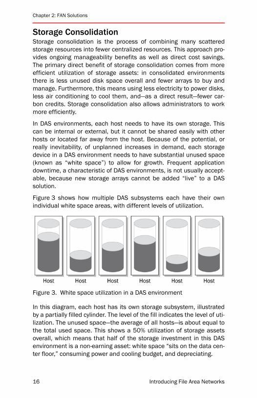
Figure 3 shows how multiple DAS subsystems each have their ownindividual white space areas, with different levels of utilization.
Figure 3. White space utilization in a DAS environment
In this diagram, each host has its own storage subsystem, illustratedby a partially filled cylinder. The level of the fill indicates the level of uti-lization. The unused space—the average of all hosts—is about equal tothe total used space. This shows a 50% utilization of storage assetsoverall, which means that half of the storage investment in this DASenvironment is a non-earning asset: white space “sits on the data cen-ter floor,” consuming power and cooling budget, and depreciating.
16 Introducing File Area Networks
Storage Consolidation
The reason that white space in DAS environments tends to be high isthat there is no way for a host in need of storage to access the whitespace located on storage attached to a different host, and thereforeeach host needs its own dedicated pool of white space to be sizedaccording to its projected worst-case need. Most hosts never actuallyuse that space, but it has to be there to prevent downtime for occa-sions when it is needed.
In a FAN, however, the major portion of white space can be kept in acentral pool, since any host can access any storage device to get atfree space when it is needed. Any host with an occasional need forstorage can get more out of the central pool on the fly. Some whitespace is still needed, but utilization is at a much higher rate, whichmeans less money spent on non-earning assets.
Not only does the FAN version have higher utilization and thereforelower cost, but it also consolidates storage subsystems into fewerdevices. Fewer devices to manage means lower power consumption,less load on the data center cooling infrastructure, reduced carbonusage, simplified support contracts, more efficient depreciationcycles, and more efficient use of administrator time.
Because of its compelling and quantifiable value proposition, consoli-dation is the single most common use case for file networks today.Designers include storage consolidation as an integral part of mostFAN solutions, even when they have a different primary designobjective.
It is not always possible or even desirable to collapse all storage intoone subsystem. Particularly in enterprise environments, there may stillbe dozens or even hundreds of arrays. However many subsystems arerequired in a storage consolidation solution, it is always fewer thanwould have been needed with a DAS approach, in addition to theirgreater utilization. Similarly, it is never possible to truly finish a consoli-dation project unless the organization performing the project stopsgrowing and stops changing. This means that there will still be multiplestorage subsystems and data will still periodically move betweenthem, even after a consolidation project is considered to be complete.
So far, this chapter does not describe anything that could not havebeen accomplished with traditional technologies. Fibre Channel SANsin particular have been enabling storage consolidation solutions formore than a decade. Indeed, the majority of enterprises today have astorage consolidation approach of one sort or another. On the surface,it might not appear that storage consolidation is a use case for FAN
Introducing File Area Networks 17

Chapter 2: FAN Solutions
technology simply because other technologies already solve the prob-lem. That being said, FANs enhance storage consolidation solutions inseveral important ways.
For example, non-FAN approaches can experience the administrativedifficulty of adding and removing storage. If hundreds of users aremapping their “Q:” drive to a particular NAS head, and IT needs toremove that head, somebody may need to “touch” all of the user sys-tems. At best, login scripts will need to be adjusted and the change willneed to be communicated outside the IT group—which will inevitablyresult in user complaints. Migrating data during a consolidation effortis also problematic for similar reasons. FAN technology provides a setof tools that fill these and other gaps and provides a complete consoli-dation solution. The next sections discuss some of the tools FANapplications use to accomplish this.
Namespace GlobalizationThe cornerstone of the FAN approach is the use of a GlobalNamespace (GNS) to virtualize users’ views of storage servers. Inshort, a GNS is to a network file system as Domain Name System(DNS) is to Internet services such as the World Wide Web. Most peopledo not know the numerical IP address of www.ebay.com, yet millionsuse it every day. Using a GNS makes storage infrastructure similar tothe Internet, that is, users access files in much the same way as theyaccess Web sites.
To understand the way in which a GNS does this, first it is useful toconsider what IT departments and end users do without a GNS.Figure 4 on page 19 illustrates the traditional approach to mappingmount points and drive letters across a network. Each mount point is“connected” to a physical file server. These relationships are usuallycreated and maintained by the IT organization. If files are moved, themapping will need to be changed on client machines. While there aremethods for automating this, none are problem-free. Typically, usersare required to log off or reboot. Administrators inevitably have to fieldquestions from confused users, or troubleshoot clients when the auto-mated solution does not work.
Troubleshooting with this approach is notoriously difficult. In a largeenvironment, there are more file servers than letters in the alphabet.This creates a problem for Windows administrators: it means that it isnot possible for all clients to have the same drive letter mappings. Forsome users, drive “E:” refers to one file server; and for others, itmeans something else entirely. When a user calls support and says, “I
18 Introducing File Area Networks

Namespace Globalization
can’t see my E: drive,” it is difficult for the help desk to help. It isunlikely that the user knows where “drive E:” is actually mapped, andequally unlikely that the help desk person can guess.
Figure 4. Network file-system mapping
Instead of mapping mount points to physical NAS heads and file serv-ers, a GNS creates a directory structure that makes logical sense tousers and to the IT department, and maps user requests to the correctphysical location to get the data. It creates a layer of abstractionbetween users’ perception of file systems and the physical location offiles. It virtualizes file systems.
Figure 5 on page 20 shows what the network file-system mappingenvironment might look like once a GNS is implemented. Under thenon-GNS paradigm, a user would need to know (or guess) what driveletter was mapped to the server with their data. If something were tochange on the server side, users would need to adapt, and potentiallylog off, reboot, and even reconfigure applications. Under the GNS par-adigm, users can see an intuitive directory structure underneath a
Introducing File Area Networks 19

Chapter 2: FAN Solutions
single drive letter. If something changes on the server side, the GNSlayer of abstraction allows the IT department to keep the users’ view ofthe file system consistent.
Figure 5. Global namespace
This is much like the way DNS provides a layer of abstraction for theInternet. The Web site www.ebay.com can change IP addresses orphysical locations on a transaction-by-transaction basis without usersneeding to know that this is happening. Similarly, when a user in a glo-bal namespace environment types in the Universal NamingConvention (UNC) path name for a file, the physical location of the fileis transparent. GNS provides a directory service analogous to DNS.
Administrators can use GNS to aggregate multiple file systems andmanage them as a single entity, regardless of physical location. Forexample, consider a company with two Engineering offices: one inHouston and the other in London, England. In the Houston office,there are two storage devices (server1 and server2) and in the Londonoffice, a single storage device It is possible to create a GNS that con-tains both sites; and in this way, users at both sites use a single drive
20 Introducing File Area Networks

Namespace Globalization
letter to access all their data, whether it is local or remote. If theadministrator needs to migrate or replicate any of the data, it will betransparent to the user, as illustrated in Figure 6.
Figure 6. Multi-site GNS Scenario
Notice that the Houston and London engineers see different filesunder their E: drives. The administrator of the GNS can set up policiesthat define the correct mapping for logical-to-physical directoriesbased on many different criteria. In this case, the definition was basedon the physical location of the client.
Like storage consolidation, GNS can be a solution in and of itself. Itcan solve operational difficulties associated with having too manydrive letter mappings, inconsistent drive mappings, and so on. Simpli-fying IT operations saves time and money directly by allowing ITpersonnel to work on more strategic projects, and indirectly by increas-ing end user productivity.
Also like storage consolidation, GNS can be part of other solutions. Forexample, using GNS will make it very much easier to migrate data fromone array, storage device, or server to another, as discussed in thenext section.
Introducing File Area Networks 21
Chapter 2: FAN Solutions
Data MigrationActive IT organizations need to migrate data, and in the most activegroups, moving data can be a full-time job, or even several full-timejobs. Business drivers for data and server migrations include:
• Storage arrays coming off lease and/or needing to be upgraded tonewer technology on a continual basis
• Servers becoming obsolete or being repurposed
• Volumes filling up and needing to be moved
• Mergers and acquisitions or internal restructuring that requirecombining and/or relocating data centers
• Application usage patterns that change over time
Whatever the cause, it is frequently necessary to move large data setsbetween NAS filters, general purpose file servers, and arrays. It mayalso be necessary to change host-to-storage mappings. Most migra-tions occur within a data center, but sometimes they occur betweensites. Indeed, migrations can occur within a data center in which theaffected devices are all attached to the same network switch, orbetween data centers located thousands of miles apart, crossingmany intermediate network devices and traversing networks runningdifferent protocols. Either way, FANs can help.
In non-FAN environments, migrations are difficult if not impossible toaccomplish without major effort and downtime. Indeed, migrationscan be so complex that a number of consulting and professional ser-vices organizations specialize in nothing else.
Issues with traditional migration approaches include:
• Non-deterministic performance
• Unknown time window for completion
• Downtime for users
• End user complaints to IT
• Complexity of change control plan
• Compatibility between heterogeneous systems
• Post-migration troubleshooting
22 Introducing File Area Networks
Data Migration
With FANs, the effort and risk of migration can be minimized, and theprocesses simplified even to the point where no downtime is requiredat all. FAN components aggregate storage across heterogeneous, geo-graphically distributed file systems, thereby enabling administrators toperform migration across devices regardless of location, vendor, orunderlying file systems. Administrators can seamlessly migrate andconsolidate data “behind the veil” of the GNS, without interruptinguser access. With the best FAN tools, a simple, intuitive user interfaceturns a formerly complex migration job into a drag-and-drop operation,and data movement tasks can be scheduled and automated by settingup policies in the application.
GNS makes data movement transparent to users, and this is extremelyvaluable, but GNS is not the only FAN component that simplifies migra-tion. FAN solutions also contain tools that actually perform themigration process. The best FAN tools can make the migration runfaster and the process predictable.
For example, a FAN toolkit might have the ability to perform byte-leveldifferencing during a migration operation. This would allow the migra-tion tool to move only the parts of files that have changed. If some filesare already on the target array, differencing technology preventsadministrators from the necessity of moving those files again. If theFAN application is particularly well designed, it could enable the migra-tion of data while users are still accessing the source volume.
Here is the scenario. An administrator starts moving data. Users areworking in the files and make changes in some—but not all—of the fileson the source volume by the time the movement completed. Most ofthe files moved to the target will be unchanged during the time it tookto move them. Differencing technology allows the administrator to syn-chronize the changed files rapidly, and then synchronize the evenfewer changes that occurred during that time. Most migrationapproaches can, at best, apply file-level differencing. Using a byte-levelapproach means that the subsequent iterations will not need to movechanged files; they will only need to move the changed parts of files,which is faster. When migrating over a WAN, it is much faster. By iterat-ing through that process, eventually the target would be synchronizedwith the source, and the cutover of the GFS pointer would occurtransparently.
In a similar way, the combination of GFS and optimized data move-ment technology can be used to create fast and transparent failover ina recovery solution as discussed in the next section.
Introducing File Area Networks 23
Chapter 2: FAN Solutions
Disaster Recover/Business ContinuanceIn the wake of recent global events, corporations and governmentagencies alike have a greater focus on Disaster Recovery (DR) andBusiness Continuity (BC) solutions. (“DR” will be used to refer to thisgeneral class of solution.) In some cases, DR solutions are driven byfiduciary duty to investors; in other cases government regulationsmandate their implementation. Whatever the driver, organizationsimplementing these solutions need to be able to move large amountsof block data reliably, quickly, and repeatably over long distances.FANs are a natural fit for organizations with DR requirements. Tradi-tional approaches to DR have a number of gaps related to replicationor backup performance, manageability, restore times, and failovertimes. All of these issues are addressed in comprehensive FANsolutions.
For example, look at the multi-site GNS scenario illustrated in Figure 6on page 21. Houston and London could be configured to work as anactive/active DR pair: so if the Houston site were to fail catastrophi-cally, London could take over, or vice versa. If this were done without aGNS, the failover operation would have to be manual, and users wouldneed to have their drive mappings reconfigured. Without other FANcomponents, synchronization of the file systems at the two sites atbest would occur at the file level, requiring entire changed files tomove constantly. This means wasted time and bandwidth, and greaterlatency between the change and the commitment of the replicatedcopy. Restoration would be at the file or even file-system level, whichwould require considerable time to move across an intercontinentalWAN.
On the other hand, if the DR solution used a FAN, none of these issueswould exist. GNS would allow transparent and automatic failover to therecovery file system at the remote site. Users would not need toreboot, and applications would not need to be reconfigured. Duringsteady state operations, only the minimum possible information wouldneed to traverse the WAN, that is, only the changed blocks of files,rather than the files themselves. Similarly, after the disaster was over,switching back to the primary site would be much more efficient,because only changed blocks would need to be moved.
24 Introducing File Area Networks
Disaster Recover/Business Continuance
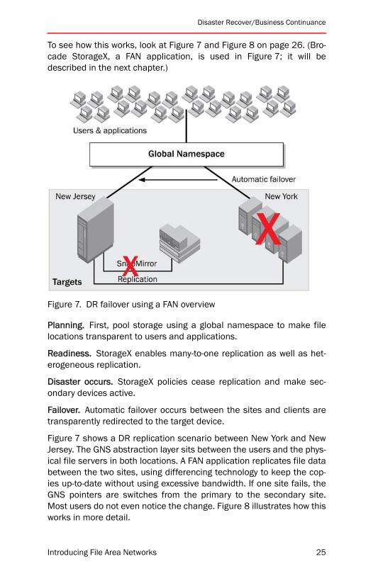
To see how this works, look at Figure 7 and Figure 8 on page 26. (Bro-cade StorageX, a FAN application, is used in Figure 7; it will bedescribed in the next chapter.)
Figure 7. DR failover using a FAN overview
Planning. First, pool storage using a global namespace to make filelocations transparent to users and applications.
Readiness. StorageX enables many-to-one replication as well as het-erogeneous replication.
Disaster occurs. StorageX policies cease replication and make sec-ondary devices active.
Failover. Automatic failover occurs between the sites and clients aretransparently redirected to the target device.
Figure 7 shows a DR replication scenario between New York and NewJersey. The GNS abstraction layer sits between the users and the phys-ical file servers in both locations. A FAN application replicates file databetween the two sites, using differencing technology to keep the cop-ies up-to-date without using excessive bandwidth. If one site fails, theGNS pointers are switches from the primary to the secondary site.Most users do not even notice the change. Figure 8 illustrates how thisworks in more detail.
Introducing File Area Networks 25

Chapter 2: FAN Solutions
Figure 8. DR failover using a FAN (detailed)
Under normal conditions, a client at Site A accesses file data on itslocal file server, and GNS information using its local name server. Amonitoring agent “watches” the servers at both sites, and a replicationagent (RA) keeps them in sync. If the Site A data center were to fail cat-astrophically, the client configuration would switch over to the Site Bnamespace replica. At the same time, the monitoring agent wouldnotice that the Site A server had failed and would update thenamespace replica to point at the Site B file server.
This category of solution works optimally to solve large-scale DR prob-lems, but it is not necessarily optimal for other WAN extension andoptimization scenarios. Fortunately, other FAN components are avail-able for those scenarios.
26 Introducing File Area Networks
WAN Performance Optimization
WAN Performance OptimizationA complete FAN solution generally includes a WAN optimization com-ponent. For DR solutions, the system described above may be optimal.However, when it is optimizing branch offices and other smaller sites,the solution is usually referred to as “Wide Area File Services” (WAFS).WAFS is designed to overcome the severe performance and infrastruc-ture challenges related to consolidation and file collaboration over theWAN.
Driven by cost and compliance concerns, businesses are attracted tothe concept of storage and server consolidation. From an IT perspec-tive, consolidation helps move businesses from existing fragmentedserver environments toward a more secure, compliant, and adaptableFAN architecture. In turn, IT can respond more rapidly and cost effec-tively to current and future business demands. This is particularlyattractive in a branch office WAN environment. It may not be possibleto have a full IT staff at each branch office. But when there is no ITpresence in the branch office, it is sub-optimal to have non-IT person-nel manage file servers and services such as print, Dynamic HostConfiguration Protocol (DHCP), DNS, domain controller, Systems Man-agement Server (SMS), and others.
Business drivers and theoretical improvements for IT present one sideof the argument when consolidation is performed in a WAN environ-ment. Consolidation brings new performance and data growthchallenges to an already overburdened IT infrastructure. Alone, thechallenges facing IT can compromise the benefits of consolidation.Collectively, they can derail the larger project—effectively underminingthe intent of consolidation.
Most distributed enterprises require file collaboration or use special-ized data management applications to ensure that everyone worksfrom a common base of files. However, user frustration due to file-access delays and subsequent user-derived workarounds can severelyundermine business requirements. Similarly, if IT administrators movedata from a remote site to a central data center, access will always beslower due to the latency and congestion prevalent in WANs.
IP optimization products are not sufficient to accelerate file sharingtraffic, and they introduce data integrity and security issues. Theseproducts employ non-file-aware, approaches, and cannot support end-to-end security mechanisms such as SMB signing or IPsec (IP secu-rity). They also lead to silent data loss in cases of WAN disruptions.
Introducing File Area Networks 27
Chapter 2: FAN Solutions
Using WAFS addresses these issues, ensuring that server and storageconsolidation projects not only meet but actually exceed user andbusiness expectations.
WAFS can deliver optimization for file-sharing protocols such as CIFS/NFS using a distributed file system implementation. Maximum scal-ability is realized by a Single Instance Storage (SIS) cache betweenremote sites and the data center. Data integrity is achieved using tech-niques such as proxy file locking, update journaling, and fullyasynchronous writeback. Branch office IT services on remote nodesmake it possible to replace all servers used for branch office func-tions. The node provides local print, DHCP, DNS, domain controller,SMS, and other services out-of-the-box to branch office users.
To enable LAN-like access to application servers accompanied by high-performance data transfers for remote users, WAFS provides two cate-gories of performance-enhancing technologies:
• Acceleration to overcome latency and design limitations in CIFS/NFS and TCP protocols
• Data reduction to prevent redundant traffic from crossing the WANand compression to reduce the amount of data when it does needto cross the WAN
A WAFS solution can be deployed in a number of different topologies tomatch the architecture and data-sharing requirements of almost anydistributed enterprise. The simplest application can be illustrated witha hub-and-spoke topology. The site that houses the data center appli-cation and file servers use a WAFS node to serve WAFS nodesdeployed at each of the branch offices in the enterprise. The WAFSnode at the branch office provides transparent LAN speed access toservers. This architecture is shown in Figure 9 on page 29.
In this diagram, one central location and several branch offices havebeen converted to a WAFS architecture. Before this conversion, eachbranch office needed file servers and services—and administrators tomaintain these platforms. The data on the file servers needed to bebacked up and replicated somehow for disaster recovery. If somethingwent wrong at a remote site, it was often necessary to send senior ITpersonnel with advanced troubleshooting skills from the central site.
The IT department in this example decided to consolidate all file dataand services into a central data center. This way, there is no need forfull IT staffing and senior IT administrators at the central site are notneeded for troubleshooting at the remote offices— greatly simplifying
28 Introducing File Area Networks

Chapter Summary
the DR solution. However, simply moving data to a central location typ-ically slows file access to an unacceptable level from a user pint ofview.H
Figure 9. High-level WAFS architecture
With WAFS, the IT department can achieve its consolidation goals with-out user impact. The WAFS nodes at the remote offices require no day-to-day management. All backups are handled from the central loca-tion, since that is where the primary data store is located. However, theWAFS nodes can serve replicated copies of users’ files locally and pro-vide local services, so that user access times are unchanged.
A customer case studies that uses WAFS technology is describedbriefly in the next chapter on page 45.
Chapter SummaryFAN solutions enhance existing network infrastructure in many ways.Performance and reliability are increased, whereas cost, downtime,and management complexity are reduced. The following chapters dis-cuss specific products used to create FANs, and how to deploy them tosolve data center consolidation, data migration, DR, and WAN perfor-mance optimization challenges.
Introducing File Area Networks 29

Chapter 2: FAN Solutions
30 Introducing File Area Networks

Introducing File Area Networks
3
Building BlocksThis chapter provides an overview of specific products that can beused to create FAN solutions and includes the following sections:
• “Brocade StorageX” on page 31
• “Brocade WAFS” on page 35
• “Brocade FLM” on page 38
• “Brocade MyView” on page 40
• “Brocade UNCUpdate” on page 41
• “Brocade Unified FAN Strategy” on page 42
• “Customer Case Studies” on page 43
• “Chapter Summary” on page 46
The products discussed form the core of the Brocade FAN product line.Only FAN-specific products are discussed. Solutions involving theseproducts also require additional products from Brocade partners. Forexample, a FAN would need storage servers such as file servers or NASheads, block storage devices such as RAID arrays, connectivitybetween those devices such as a Brocade Fibre Channel SAN, andfront-end connectivity such as an IP LAN and/or WAN.
Brocade StorageXEach storage device that needs to be managed independentlyincreases the administrative costs in distributed file storage environ-ments. As a result, today’s IT organizations require new ways tosimplify file system management, enhance data access, and reducedata management costs.
31
Chapter 3: Building Blocks
Brocade StorageX is an integrated suite of applications that logicallyaggregates distributed file data across heterogeneous storage environ-ments and across CIFS- and NFS-based file systems. It also providespolicies to automate data management functions. Administrators useStorageX to facilitate such tasks as:
• Data migration and consolidation
• Business Continuity/Disaster Recovery (BCDR)
• Remote site data management
• Information Lifecycle Management (ILM)
• Storage optimization
• Data classification and reporting
StorageX provides administrators with powerful tools and policies toperform such tasks without causing downtime for users. Moreover, itdirectly addresses the needs of both administrators and users byincreasing data availability, optimizing storage capacity, and simplify-ing storage management—all of which contribute to significantly lowercosts for enterprise data infrastructures.
The foundation of StorageX is the global namespace (GNS), which uni-fies and virtualizes heterogeneous file data stored throughout anenterprise by pooling multiple file systems into a single, logical file sys-tem. In general, it does for file storage what DNS does for networking:it enables clients to intuitively access distributed files without knowingtheir location (just as they access Web sites without knowing their IPaddresses). This transparency of the storage architecture can spanthe enterprise and make the physical location of data irrelevant tousers.
GNS provides the following key benefits:
• Data management and movement are both transparent and non-disruptive.
• Data changes are automatically updated and require no clientreconfiguration.
• Administrators can manipulate storage without affecting howusers view and access it.
• Data management and movement require far less administrativeeffort and time.
32 Introducing File Area Networks
Brocade StorageX
• Administrators can manage data on heterogeneous, distributedstorage devices through a single console.
• Users have a single, logical view of files with access through a sin-gle drive letter.
StorageX allows administrators to seamlessly migrate and consolidatedata from multiple heterogeneous file servers onto one or more fileservers. GNS and StorageX migration policies shield users from physi-cal changes during migrations, and the policy engine significantlyreduces the administrative tasks required. This, in turn, minimizesuser downtime, while access to data remains intact.
In addition, Brocade StorageX:
• Enables automatic share creation
• Copies security attributes
• Integrates with NTFS Change Journal
• Integrates with Microsoft VSS snapshots to enable open andlocked file copying
As organizations are faced with both planned and unplanned networkoutages, business continuity planning has come to encompass muchmore than just disaster recovery. Although many products currentlyaddress the need to replicate data in preparation for a network out-age, very few address the need to fail over users in a fast andseamless manner. In addition to ensuring user failover, administratorsmust find a way to centralize business continuity management in het-erogeneous, distributed environments while keeping IT costs at aminimum. StorageX uses GNS and disaster recovery policies to sup-port cost-effective, seamless failover across geographically distributedsites while giving administrators a centralized way to manage the glo-bal failover process.
StorageX provides administrators with a comprehensive solution formanaging geographically distributed data. With the GNS, administra-tors have a single view of data across multiple locations and canmanage it as a single entity. StorageX includes a Replication Manageras well as policies for replicating data to a central backup location,thereby eliminating the need to maintain a tape backup infrastructureat each location. These policies enable file replications of any size andany distance in heterogeneous environments.
Introducing File Area Networks 33

Chapter 3: Building Blocks
Definable data lifecycle management policies enable tiered storagearchitectures, which provide an efficient approach to meeting ILMrequirements. StorageX uses GNS to facilitate the ILM architecture.Moving data to secondary storage reduces hardware acquisition costswhile enabling administrators to align backup policies and invest-ments with the business value of data. Using StorageX to create andimplement a tiered storage architecture, administrators can createpolicies to automatically migrate data based on criteria such as age,usage patterns, and file size.
Optimizing capacity utilization across the enterprise is another benefi-cial advantage of StorageX. Using GNS together with load-balancingpolicies, administrators can create logical pools of storage that alignwith business requirements, and then manage and optimize resourcesassigned to the namespace. In addition, administrators can centrallyview and manage enterprise-wide capacity utilization—and transpar-ently and non-disruptively balance capacity across multiple devices.
StorageX can be used to centrally manage data at remote sites as wellas facilitating consolidation and migration tasks within a data center.Administrators can schedule policies to automatically replicate datafrom remote sites to a central data center at set intervals. These poli-cies can be scheduled to run during times of low network utilization,and Byte-Level File Differencing Replication can be turned on to fur-ther conserve network bandwidth.
Once data has been replicated to a central location, it can be backedup there, eliminating the need for tape backup infrastructure andbackup administration at each remote location. This entire processcan be centrally scheduled and managed through a single StorageXuser interface.
StorageX provides administrators with robust reporting capabilitiesthat enable them to support key IT projects. It uniquely enables admin-istrators to classify data based on a variety of business-relevantcategories, including department, location, project, user group, fileage, file size, and last access time. After the classification criteria arespecified, administrators can run customizable reports to determinedata migration requirements and facilitate departmental charge-backbased on capacity usage.
As a non-proprietary software solution, Brocade StorageX fits seam-lessly into existing IT environments. It integrates with and operates onexisting file systems, uses standard protocols, and requires no client
34 Introducing File Area Networks

Brocade WAFS
software or agents. Because StorageX is an out-of-band solution anddoes not reside in the data path, it does not cause latency or perfor-mance issues.
This solution is discussed in more detail in “Chapter 5: Brocade Stor-ageX” starting on page 73.
Brocade WAFSManaging branch office IT infrastructures is often complex, time-con-suming, and resource-intensive. Brocade Wide Area File Services(WAFS) is designed to address some of the most difficult branch officeIT issues, including storage and server proliferation, backup andrestore management, and rising ownership costs. WAFS is an innova-tive solution that provides LAN-like access to files shared across WideArea Networks (WANs)—enabling organizations to consolidate theirassets while protecting remote data. For enterprises with distributedlocations, WAFS can streamline branch office IT operations, improveoperational efficiency, increase file performance across the WAN, andcentralize data management.
Brocade WAFS is available as software that runs on industry-standardservers, Branch Office Software, or as a standalone appliance runningWAFS, as shown in Figure 10. The term “node” refers to a BrocadeWAFS appliance or a server running Branch Office Software. A “Corenode” resides in the central data center, and “Edge nodes” reside ateach remote site in the enterprise. The centralized Core node andremote Edge nodes communicate through a Storage Caching-over-IP(SC-IP) protocol optimized for the performance and reliability charac-teristics of a WAN. This design enables highly efficient data caching,thereby eliminating the need for data replication, while still ensuringfile consistency and supporting global file sharing across theenterprise.
Figure 10. Brocade WAFS Appliance
Introducing File Area Networks 35
Chapter 3: Building Blocks
One of the greatest advantages of Brocade WAFS is its ability tostreamline IT operations in remote locations. Because it enables dis-tributed enterprises to centrally manage branch office IT services—including file, print, network, and Web caching services— BrocadeWAFS helps reduce remote office servers, storage and backup hard-ware, software, and other related costs. This type of centralizedmanagement significantly reduces the need for remote site IT person-nel and expensive site visits, including the need to ensure properbackups of branch office data.
With all users working from a single source file, organizations can col-laborate as part of a global file-sharing process. Persistent loggingprovides file protection and integrity, while caching and file differenc-ing allow users to view changes in real time. In addition, multiple file-handling technologies accelerate access to files and their associatedapplications, while also enabling continued productivity during WANdisruptions.
Brocade WAFS is designed to improve both administrator and user pro-ductivity by enabling a more efficient IT environment. Key efficienciesfor file transport include:
Remote caching. Enables a single file copy to be shared among multi-ple users at a remote location.
Storage Caching over IP (SC-IP). Eliminates the transmission of CIFSmanagement calls across the WAN.
Wide area dictionary compression. Eliminates redundant transmis-sion of file data through byte-level monitoring.
Performance flexibility. Supports asynchronous or synchronous write-back of file data based on file type and performance requirements.
File-aware differencing. Transmits only changes in the file data toreduce WAN traffic and transport time.
File streaming to cache. Allows users to begin working with an appli-cation even before the entire file is available.
36 Introducing File Area Networks
Brocade WAFS
Bandwidth-throttling flow control. Manages file traffic by time of day tomeet Quality of Service (QoS) requirements.
WAFS was designed from the ground up for native integration withMicrosoft platforms in order to support secure and consistent fileaccess policies. Key support includes:
• CIFS protocol management
• Security mechanisms such as Active Directory, SMB signing, andKerberos authentication
• Systems Management Server distribution services
To help organizations comply with their internal business objectivesand industry regulations, Brocade WAFS:
• Is designed to survive common WAN disruptions, helping to guar-antee data coherency and consistency
• Supports encrypted files sent over the WAN for added security
IT managers need to protect data across all application and network con-ditions. WAFS does that, and utilizes synchronous logging to persistentRAID storage for greater reliability. By increasing security and centralizingfile management, WAFS enables branch offices to leverage data center-class regulatory compliance and disaster recovery strategies.
WAFS is ideally suited for large-scale distributed organizations. Typicaldeployments involve supporting up to about 100 remote offices of upto about 50 users each. However, it is capable of scaling to support asmany users for each remote node with up to 49 for each core. Organi-zations with even larger design problems can easily deploy multipleWAFS cores, break their problem up into multiple smaller and moremanageable chunks. See “Appendix C: WAFS Sizing Guidelines” start-ing on page 197 for more information.
Brocade WAFS is a highly effective solution for cost-conscious organi-zations that want to:
• Increase server and storage asset utilization to maximize thevalue of existing IT investments
• Reduce capital expenditures and ongoing management costs atbranch offices
• Improve both administrator and user productivity
• Free up network bandwidth to handle larger workloads
• Gain the benefits of centralization and consolidation
Introducing File Area Networks 37

Chapter 3: Building Blocks
Brocade WAFS can be deployed independently, or it can be combinedwith some of the other Brocade FAN offerings. For example, beforeinstalling WAFS nodes in branch offices, organizations can performremote file server migration and consolidation to a centralized datacenter using Brocade StorageX. This way, organizations can manageWAFS data on heterogeneous, geographically distributed storagedevices from a single console. As a result, ongoing data managementand movement requires less effort and time. Moreover, the StorageXGNS enhances business continuity by enabling seamless failover inthe event of a device failure.
This solution is discussed in more detail in “Chapter 6: Brocade WAFS”starting on page 113.
Brocade FLMIn most IT environments, all file data is not created equal—especiallyas data growth occurs unevenly on storage systems across the enter-prise. Over time, imbalanced storage growth results in increasedexpenditures due to the proliferation of storage devices, acute man-agement challenges for IT administrators, and difficultly in ensuringcompliance with regulatory requirements.
However, IT organizations can reduce the total cost of storage owner-ship by actively managing data throughout its lifecycle from creation todisposal, and by aligning storage policies with business priorities andregulatory requirements.
Brocade File Lifecycle Manager (FLM) is an administratively defined,policy-based data solution that manages the lifecycle of file data onNetwork Appliance (NetApp) storage systems. FLM helps administra-tors by analyzing, classifying, blocking, moving, organizing, anddeleting file data—using policies defined with organizational gover-nance objectives that reflect the business value of data.
The FLM solution optimizes the management of data based onattributes and access patterns, while maintaining user access to files.In addition, FLM simplifies compliance through information policy-based retention and maintenance.
By deploying FLM and implementing tiers of disk-based storage, orga-nizations can achieve significant reductions in overall storageexpenses. FLM can also result in increased volume capacity as inac-tive data is automatically moved to secondary storage.
38 Introducing File Area Networks
Brocade FLM
Separately, FLM reduces the costs associated with backup—includingtape hardware, backup software, and management costs—as lessimportant data gets transferred to secondary storage.
Brocade FLM supports a wide range of policy parameters based oncorporate data storage and retention guidelines to simplify datamanagement:
Adaptive archival algorithms. Excludes certain restored files fromfuture migrations.
Archival storage manager. Defines multiple offline stores as a pool,eliminating the need to set up large volumes as secondary stores.
Blocking. Prevents unwanted file types from being stored on the pri-mary storage.
Classification. Analyzes and classifies file data based on parameterssuch as location, type, name, age, size, attributes, and volumeutilization.
Migration automation. Periodically migrates files that match thedefined criteria and scope to multiple secondary storage devices.
Primary space optimizer. Automatically re-migrates a restored fileback to the secondary store.
Restore control. Minimizes impact on storage capacity utilization andnetwork bandwidth resulting from inadvertent data restores.
Retention/deletion. Deletes files matching parameters, such as thosesurpassing long-term retention limits.
Simulated migration. Performs detailed “what if” analyses andreports the results to support capacity planning and network band-width utilization planning.
This solution is discussed in more detail in “Chapter 8: Brocade FLM”starting on page 153.
Introducing File Area Networks 39

Chapter 3: Building Blocks
Brocade MyViewIT organizations routinely need to answer complex questions about filepermissions, such as which categories of files a given user can accessor which users can access a given classification of files. Unfortunately,file data (and the right to access it) is one of the most difficult items tocontrol in the enterprise, because the information and managementthereof tend to be highly distributed.
To complicate matters, most current IT solutions do not focus onsecuring file data against threats from within the enterprise, where themajority of security breaches actually occur. It is well established thatthe vast majority of security problems are internal, not coming fromoutside hackers or Internet-bourn viruses, but from disloyal or disgrun-tled employees. In light of this, it is odd that current security solutionsdo not adequately provide administrators with a comprehensive viewinto internal enterprise file data access rights. Equally problematic isthe fact that users do not intuitively know which resources they canaccess and where those resources are located.
Brocade MyView is a global resource access management solutionthat provides personalized, secure access to Windows file resourcesacross the enterprise. With this innovative solution, organizations nolonger have to sacrifice their business objectives to achieve their datasecurity compliance requirements.
A key component of Brocade MyView is the Global Resource AccessMatrix (GRAM), which gives administrators and auditors a central viewof user access rights to distributed data as well as detailed reportingcapabilities. This unique approach results in tighter security practicesand simplified auditing for Sarbanes-Oxley, Federal Information Secu-rity Management Act (FISMA), Health Insurance Portability andAccountability Act (HIPAA), Personal Information Protection and Elec-tronic Documents Act (PIPEDA), and other security compliancerequirements. In addition, MyView dynamically builds personalizednamespaces for every user in an enterprise to simplify access to dataand further enhance security.
Brocade MyView addresses internal data security requirements by pro-viding a fast, automated way to generate a comprehensive GRAM. TheGRAM identifies which users have access (including the level ofaccess) to which file resources across the distributed enterprise basedon identity management, user credentials, and security permissions.Innovative technology enables the GRAM to efficiently support thou-sands of users and resources across the enterprise, dynamicallycomputing resource access changes as necessary. As a result, admin-
40 Introducing File Area Networks

Brocade UNCUpdate
istrators can easily report and manage security permissions to modifyuser access to resources. The GRAM is constantly updated to reflectthe current state of user identities and resource access permissions.Brocade MyView provides a fast and efficient way for administratorsand auditors to produce comprehensive reports that help identifypotential security breaches and enforce internal data security policies.
This solution is discussed in more detail in “Chapter 7: BrocadeMyView” starting on page 145.
Brocade UNCUpdateAs many IT organizations have discovered, storage migrations can beextremely disruptive to business operations. If users and applicationsare tied to specific share and file locations through hard-coded Univer-sal Naming Convention (UNC) path names or shortcuts, administratorsneed to take extra precautions to ensure that such linkages are main-tained as part of the migration process. UNC references can occurinside a variety of documents, applications, and other files, whichmakes this operation particularly difficult to manage.
Brocade UNCUpdate gives storage administrators a reliable tool forreporting on files that contain UNC references to storage resourcesunder consideration for migration. UNCUpdate can report on UNCentries encountered in a wide variety of files, providing administratorswith the option to update UNC references to target the storageresource at its new location.
The easy-to-use UNCUpdate interface helps administrators migratedata to a new location by scanning directories for files containing UNCpaths, which might need to be updated to reference items at their newlocation. It enables administrators to locate embedded UNC pathsstored in a file in clear text. As a result, administrators can locate andmodify UNC paths in text files, Microsoft Word, PowerPoint, and Exceldocuments, as well as update Windows Explorer shortcuts.
UNCUpdate provides significant advantages to both administratorsand users. File migration without Brocade UNCUpdate can be a man-ual, labor-intensive process that requires locating and updating user-generated shortcuts and embedded lings within files. By automatingthe link synchronization process for files containing UNC paths thatneed to be updated, Brocade UNCUpdate promotes business continu-ity—helping to eliminate potential user downtime caused by brokenlinks, shortcuts, and UNC references following a migration.
This solution is discussed in more detail in “Chapter 9: BrocadeUNCUpdate” starting on page 183.
Introducing File Area Networks 41
Chapter 3: Building Blocks
Brocade Unified FAN StrategyEach of the Brocade FAN-enabling products can be used in a standal-one manner with storage products from a variety of Brocade partners.Alternately, many of the FAN products can be used in combination witheach other. The combination of StorageX and FLM was discussed ear-lier in this chapter, and many complex combinations are also possible.Brocade UNCUpdate is a natural fit for any migration project, for exam-ple: it can greatly simplify the initial deployment of a GNS during rolloutof StorageX by reporting on and updating UNC links within files.
Of course, additional testing and validation is appropriate when rollingout combined solutions, and in some cases it would be appropriate tostage rollout over time. For example, if you decide to use StorageX andFLM, it might be practical to roll out StorageX first, and then add FLMlater rather than adding both at once. This would allow administratorsto develop and refine site-specific policies and practices associatedwith the first product before introducing the second.
This caveat is not just a FAN best practice. As a general best practicewith any new technology, you should take extra care when deployingmore complex solutions. Brocade is committed to continuing its test-ing, validation, and development efforts to expand and simplify thenumber of combined solutions that are supported, and customers canlook forward to an increasing number of pre-certified solutions. Bro-cade and its partners offer complete solutions to meet a wide range oftechnology and business requirements, including education and train-ing, support, and professional services to help IT professionalsoptimize their technology investments.
Figure 11 illustrates one way a unified FAN deployment might look, ifall of the products discussed in this chapter were used in concertwithin a single IT environment.
42 Introducing File Area Networks
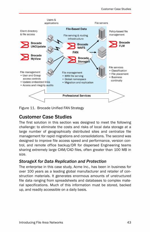
Customer Case Studies
Figure 11. Brocade Unified FAN Strategy
Customer Case StudiesThe first solution in this section was designed to meet the followingchallenge: to eliminate the costs and risks of local data storage at alarge number of geographically distributed sites and centralize filemanagement for rapid migrations and consolidations. The second wasdesigned to improve file access speed and performance, version con-trol, and remote office backup/DR for dispersed Engineering teamssharing extremely large CAM/CAD files, often greater than 100 MB insize.
StorageX for Data Replication and ProtectionThe enterprise in this case study, Acme Inc., has been in business forover 100 years as a leading global manufacturer and retailer of con-struction materials. It generates enormous amounts of unstructuredfile data ranging from spreadsheets and databases to complex mate-rial specifications. Much of this information must be stored, backedup, and readily accessible on a daily basis.
Introducing File Area Networks 43
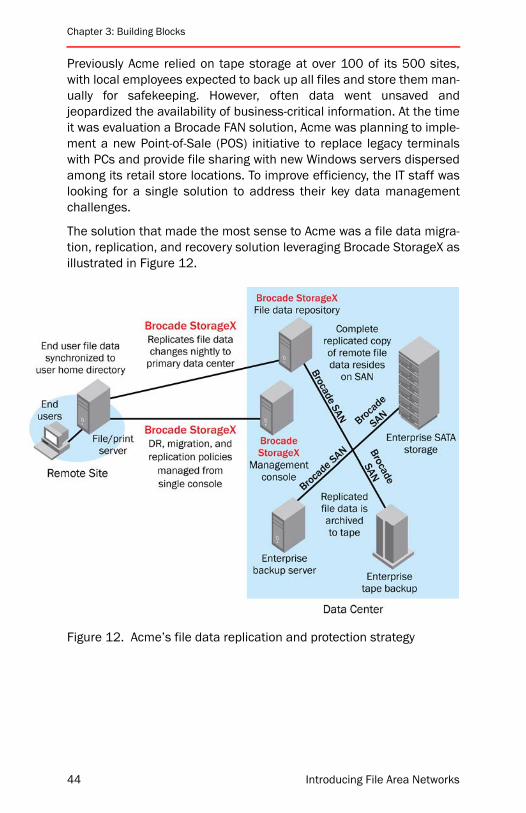
Chapter 3: Building Blocks
Previously Acme relied on tape storage at over 100 of its 500 sites,with local employees expected to back up all files and store them man-ually for safekeeping. However, often data went unsaved andjeopardized the availability of business-critical information. At the timeit was evaluation a Brocade FAN solution, Acme was planning to imple-ment a new Point-of-Sale (POS) initiative to replace legacy terminalswith PCs and provide file sharing with new Windows servers dispersedamong its retail store locations. To improve efficiency, the IT staff waslooking for a single solution to address their key data managementchallenges.
The solution that made the most sense to Acme was a file data migra-tion, replication, and recovery solution leveraging Brocade StorageX asillustrated in Figure 12.
Figure 12. Acme’s file data replication and protection strategy
44 Introducing File Area Networks
Customer Case Studies
StorageX and WAFS Working TogetherABC Design is ranked among the nation’s top design firms andemploys more than 500 staff in 20 offices in the southeast. Using adistributed business model, ABC offices are responsible for providinglocal resources and staff on a regional basis. The remote offices typi-cally enlist ABC Engineers throughout the company’s enterprise todeliver the necessary expertise in land development, transportation,utilities, water resources, and ecology. No matter which branch officeis managing the project, the strength of the entire enterprise is avail-able, collaborating effectively as if they were all in one place.
To accomplish this objective, ABC relies on its WAN, however, the shar-ing of massive Computer-Assisted Design (CAD) files, often 100 MB insize, was becoming more and more unworkable. For example, oneuser might have to wait up to 30 minutes to download a file, and ifanother user was updating the same file, an entire day’s work wassometimes overwritten.The challenge: a centralized data managementsolution that would enable real-time file collaboration among the Acmeoffices.
Introducing File Area Networks 45
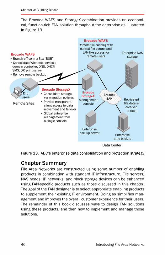
Chapter 3: Building Blocks
The Brocade WAFS and StorageX combination provides an economi-cal, function-rich FAN solution throughout the enterprise as illustratedin Figure 13.
Figure 13. ABC’s enterprise data consolidation and protection strategy
Chapter SummaryFile Area Networks are constructed using some number of enablingproducts in combination with standard IT infrastructure. File servers,NAS heads, IP networks, and block storage devices can be enhancedusing FAN-specific products such as those discussed in this chapter.The goal of the FAN designer is to select appropriate enabling productsto supplement their existing IT environment. Doing so simplifies man-agement and improves the overall customer experience for their users.The remainder of this book discusses ways to design FAN solutionsusing these products, and then how to implement and manage thosesolutions.
46 Introducing File Area Networks

Introducing File Area Networks
4
Design ConsiderationsThis chapter will familiarize you with the major considerations involvedin FAN design. It discusses some of the choices that a designer mustmake and factors to think about when making these choices in the fol-lowing sections:
• “Compatibility” on page 48
• “Network Topologies” on page 50
• “Reliability, Availability, and Serviceability” on page 52
• “Performance” on page 61
• “Scalability” on page 62
• “Total Solution Cost” on page 63
• “WAN” on page 63
• “Implementation and Beyond” on page 66
• “Planning for Troubleshooting” on page 70
• “Chapter Summary” on page 71
Some of the subtopics in this chapter are complex and have entirebooks devoted to them. In such cases, this chapter provides only anoverview: a comprehensive discussion is beyond the scope of an intro-ductory treatment.
As with most IT infrastructure design, designing FANs involves balanc-ing conflicting needs and reaching a compromise when necessary. Forexample, the requirement to deploy a low-cost network conflicts withthe requirement to deploy a network with high availability. Because ofthis, FAN design is often about making trade-offs. This chapter dis-cusses FAN requirements and provides insight to help designers makethe right decision among conflicting requirements.
47

Chapter 4: Design Considerations
The intent of this book is not to lay down rigid laws of FAN design.Since every network has slightly different requirements, there are noabsolute rules about the “right” way of doing things that can cover allscenarios. The intent is to show you design areas that you need to con-sider, and to provide recommendations based on industry-acceptedguidelines and best practices.
The first sections cover some of the areas of concern that apply to anyFAN design, regardless of variables such as protocol, distance, topol-ogy, or performance. These factors have such wide-rangingapplicability that it is important to keep them in mind when making allsubsequent evaluations. These sections discuss the areas of generalconcern, and then describe how they apply to FAN technology inparticular.
CompatibilityThe first thing to consider when designing a FAN is the compatibility ofeach piece of infrastructure equipment with the rest of the infrastruc-ture, and with each host or storage device which may interact with it. Ifdevices are not compatible, then the network will not function, so anyfurther considerations are simply irrelevant.
When devices are compatible with each other, it means that they arecapable of being connected to each other, either directly or across anetwork. It means that they can “talk.” This can apply equally to hard-ware and software.
For example, it is necessary for a Network Interface Card (NIC) driver tobe compatible with the operating system in its host. If the driver onlyworks with Windows and the host is running Solaris, they are incom-patible. This is not an example of a piece of hardware beingcompatible (or not) with a piece of software, but rather of two softwarepackages being incompatible with each other. Similarly, the NIC hard-ware must be compatible the hardware in the host: a PeripheralComponent Interconnect (PCI) NIC cannot be installed in a Solaris hostthat has only free Serial BUS (SBUS) slots.
Fortunately, File Area Networks rarely have compatibility issues at thislevel. When such compatibility issues do arise, they can be handled byIT personnel using standard troubleshooting techniques. Virtually all ITorganizations have personnel and processes in place to handle thislevel of compatibility problem.
48 Introducing File Area Networks

Compatibility
However, in the context of a FAN, compatibility applies to all hardwareand software components used from end to end—from the applicationto the final storage location. For example, it is possible for a NIC to becompatible with a storage device and the LAN hardware in-between,but still not be compatible with a feature of the LAN such as VirtualLAN (VLAN) tags. Similarly, a FAN application such as Brocade Stor-ageX needs to be compatible with its host OS, its host’s NIC, the LANequipment used, the network file system protocol in place, and thestorage device(s) that it is managing.
Areas to evaluate for compatibility include:
• Upper Layer Protocol
Do all devices in the chain use the same protocols, for example,do all devices follow the NFSv3 standard, or are some devicesusing NFSv2 or NFSv4? Do they all use the standards in the sameway? Even if the correct packets are being sent between twodevices, the vendors still need to have worked together to insure aconsistent interpretation of the standards.
• Node to Node
Protocols such as NFS operate between nodes, but these are notthe only node-to-node behaviors that can cause compatibilityissues. For example, if a volume used by a host is being synchro-nously replicated, a timing issue between primary and replicatedstorage can delay commitment notices to the application. Withperformance sensitive applications, this can cause more than justa slow response.
• Node to Switch
Will the node (host or storage) be able to attach to the LAN? Thisrequires that it follow certain protocols defined in standards, andimplementation details must also be compatible. For example, if aNIC is using jumbo packets and its switch does not support thefeature, the connection will fail.
• Failure Cases
Evaluate all components in the chain: cables, media, switch, eventhe entire network. Look at each component and decide how thenode will behave if that component fails completely, or what willhappen if it becomes unstable. (Unstable components can beworse than failed components.) Sometimes components are com-patible in steady state, but incompatibilities manifest when errorsoccur.
Introducing File Area Networks 49

Chapter 4: Design Considerations
Without end-to-end compatibility at all layers, it is not possible for asolution to work at all. Even if a solution has end-to-end compatibilityat the transport layer, an incompatibility at the application layer couldstill prevent it from being a viable option. Brocade has vastly moreexperience in this area than any other vendor where SANs are con-cerned, and has applied this expertise to FAN testing. However, justusing Brocade solutions cannot guarantee end-to-end compatibilitybetween nodes—it is still necessary to evaluate whether or not a partic-ular host will work together with a particular NAS head, and so on.
Network TopologiesThere are a number of different definitions for the term “topology”depending on context. In the context of network design, it is most com-mon for topology to refer to the geometrical arrangement of switches,routers, and other networking infrastructure elements that form thenetwork infrastructure, and the way in which these elements commu-nicate with each other.
There are literally an infinite number of possible topologies, and therobust architecture of IP routing protocols does allow arbitrarily com-plex networks to be built. Fortunately, in the vast majority of real-worldcases, it is possible to use simple solutions. This means that few topol-ogies are typically used as the basis for FANs, and these are combinedor varied to fit the needs of specific deployments. These topologies arepopular because they yield networks with superior scalability, perfor-mance, availability, and manageability. In fact, the choice of topologyhas such a profound impact on the properties of a FAN that manydesigners consider it to be the single most important decision point inthe design process.
Topology NamesWhen a network diagram is created, the infrastructure equipment canbe seen to form geometrical shapes. Topologies are named based onthe shapes that they create. The most common topologies for FANsinclude:
• Cascade
• Ring
• Mesh
• Star
50 Introducing File Area Networks

Network Topologies
It is no coincidence that these FAN topology names are familiar to SAN,LAN, MAN, and WAN professionals. The same principals that makethese designs function in other networking arenas cause them to beused in FAN design as well.
However, it is important to realize that topology names usually meansomething a bit different in the context of a FAN. This is because a FANis an overlay network.
Overlay NetworksComputer networks all use protocol stacks, and this allows for greaterflexibility. For example, the SCSI protocol is not inherently networkable.It can address only a tiny number of devices and has no concept ofrouting. It is not scalable or flexible at all. However, when SCSI ismapped on top of Fibre Channel, it becomes massively flexible andscalable. (At this time of this writing, Brocade has worked with severalcustomers designing multi-hundred-thousand-port FC solutions.)When laying a non-networking protocol (for example, SCSI) on top of anetworking protocol (for example, FC), the topology is straightforward.It is the topology of the networking protocol that is relevant.
However, if a designer lays a more advanced protocol on top of a net-working protocol, then each of those layers can have a relevanttopology. For example, it may be that six sites are connected to eachother using a ring topology WAN. This design could have been dictatedby the availability of long-distance links or by financial considerations.In this case, the term “ring” defines the physical topology of the IPWAN
But perhaps five of the sites are branch offices and have WAFS nodesthat use the sixth site as a central storage consolidation location. Inthis case, the WAFS design also has its own topology: a star. There arefive arms radiating from a central point. The star topology of thehigher-level networking component sits on top of the lower-level ring.
It is important for FAN designers to understand both levels of networktopology, as both relate to the way in which the FAN will perform. Theunderlying IP network will have performance, reliability, and availabilitycharacteristics defined by its ring topology. This means that the FANwill inherit these characteristics. However, the FAN will also have char-acteristics related to its star topology. For example, the point of thestar is a central management location, which is not a characteristic ofa ring topology.
Introducing File Area Networks 51

Chapter 4: Design Considerations
Ideally the physical topology of the underlying network and the logicaltopology of the overlay network should be the same, but this is notalways practical. FANs are almost always built on top of pre-existingnetworks, and the FAN designer usually has to adapt to what is alreadyin place. At most, the designer is limited to making incremental adjust-ments to the existing network topology. The important thing in suchsituations is to make sure that the relationships between the differentlevels of topology are understood before deployment, so that any nec-essary adjustments to deployment plan, FAN design, or existingnetwork can be made before release to production.
Reliability, Availability, and ServiceabilityThese three topics are often collectively referred to as “RAS.” Whileeach RAS component is substantially different from the others, theyeach have an effect on the overall functionality of a product, network,or solution. Designers must keep RAS in mind when selecting compo-nents and when choosing a top-level network architecture.
ReliabilityReliability is a measure of how much time a component is statisticallyexpected to be working versus how much time it is expected to requireservice for failures. Hardware and software components both havereliability characteristics. If fact, so do underlying networks, overlaynetworks, and end-to-end solutions.
One way to look at reliability is that it is a measure of how often servicepersonnel need to “touch” a system. A “reliability event” occurs anytime service is needed, even if the component is still online for theduration of the service. For example, if a LAN switch has redundant hotswappable power supplies and one fails, the switch will remain onlineduring the replacement, but a reliability event will still have occurred.
Designers must consider reliability when selecting system compo-nents for two reasons:
1. Higher reliability means lower ongoing support cost. Each time acomponent fails, a support action must take place. There may behardware replacement costs, support personnel costs, and oppor-tunity costs when people repairing a system are not working onother more strategic activities.
2. In some cases, low component reliability can translate into sys-tem-wide downtime. In other words, a reliability event can becomean availability event, as will be shown in the next section.
52 Introducing File Area Networks
Reliability, Availability, and Serviceability
The most common measures of reliability are Mean Time BetweenFailures (MTBF) and Mean Time To Repair (MTTR.) Respectively, theserefer to how often a component is expected to fail, and how long it gen-erally takes to fix the component when a failure occurs. Designersshould look for components with high MTBF and low MTTR.
Reliability applies to FAN solutions in a number of ways, and FANdesigners should understand and account for each of these.
Underlying Network ReliabilityThe largest impact of reliability events usually relates the staffing bur-den of ongoing maintenance. It may or may not be the responsibility ofthe FAN team to maintain the underlying network, but even if not, thereare still potentially relevant secondary considerations. For example, asindicated above, a reliability event can potentially become an availabil-ity event. If the underlying network becomes unstable or unavailable, itwill not be possible for the overlay network to function effectively. FANdesigners should evaluate how reliable the underlying network will be,who will be responsible for maintaining it when components fail, andhow likely failures are to create instabilities and/or availability events.
File Server/NAS Head ReliabilityThe same two general statements apply to the reliability of the plat-forms serving the FAN file systems. However, the impact of a failure atthis level can be radically different. If an underlying network path failsbetween a host and its storage, perhaps the network will have resil-iency built in which can provide an alternate path rapidly andtransparently. In most modern LAN/MAN/WAN designs, this is thecase, but it is rarely the case with NAS heads or file servers. Instead,clustering approaches are required to create resiliency at that level.The FAN designer should understand the reliability of the file systemserver platforms, who is responsible for their maintenance, which reli-ability events can become availability events, and what is likely tohappen to the FAN if a file system does go away during such an event.
FAN Platform ReliabilityFAN platforms are the systems on which FAN-specific software is run-ning. This could include WAFS nodes, general purpose servers runningBrocade StorageX, NAS heads running FLM components, or serversrunning GNS and other similar services. The same general categoriesof impact consideration apply: who will fix it if it fails, and what is thelikely impact to availability. The distinction is that FAN platforms arelikely to have a direct impact on FAN operations, and it is almostalways the responsibility of the FAN team to deal with such issues. It isthe job of the FAN designer to ensure that FAN platforms have good
Introducing File Area Networks 53
Chapter 4: Design Considerations
reliability metrics such as high MTBF and low MTTR, and that the over-all FAN architecture is robust enough to withstand the outage if areliability problem becomes an availability event. This is generallyaccomplished through the use of redundant components such aspower supplies, in combination with some variation on clustering.
AvailabilityAvailability of a system is a measure of how much time it is able to per-form its higher-level functions, such as serving files to end users. Sinceavailability is generally considered the most important RAS element,this subsection is more extended than the other two. As with reliability,both hardware and software play a role. However, availability is notnecessarily impacted by failures in components.
For example, assume that the system being analyzed is a network filesystem. Ultimately, the files on that file system “live” on block storagedevices, so the availability analysis would start there. Most modernenterprise storage devices have redundant power supplies to handlefailures gracefully. If one fails, the system has experienced a reliabilityevent, since the dead power supply will need to be “touched” by ser-vice personnel. Indeed, more supplies implies more frequent supplyfailures, so redundant supplies will actually decrease reliability. How-ever, the system and its application are still available during thisfailure: the storage device can get power through the other supply. Atsome point, someone will need to replace the supply, but even this willnot cause downtime.
File system availability is usually considered to be the most importantconsideration in FAN design overall. Problems with availability have animpact at the end-user level, rather than being contained within IT. Inthe previous example, the failure caused a reliability event whichrequired service personnel to replace the part, but the file systemstayed online. If a non-redundant component failed—such as the hostoperating system or motherboard on the file server—then an availabil-ity event would have occurred, which would require both serviceinvolvement and application downtime. Given a choice between morefrequent reliability events versus more frequent availability events,most designers chose the former.
This is important because often the measures instituted to increaseavailability also decrease reliability. If each system had only one powersupply, then statistically there would be fewer service events. However,when a reliability event did occur, it would also cause an availabilityevent.
54 Introducing File Area Networks
Reliability, Availability, and Serviceability
The most common measure for this system characteristic is “nines ofavailability.” As in, “this application has five nines of availability.” Italso may be abbreviated to simply “nines,” as in, “this is a five-ninesapp.” This measure refers to the percentage of time that a system isavailable. “Five nines” means that a system is available 99.999% ofthe time or more. To put it another way, it means that the system isunavailable no more than about 0.0001% of the time, which comes toabout five minutes each year.
In order to achieve five nines of availability for a FAN, designers mustanalyze each component involved in the overall system. This includes:block storage on which the file data resides
• The SAN and FAN networks
• The file servers or NAS heads
• Name and directory services
• End user client service failover mechanisms
• Data center power infrastructure
and so on. Each component—hardware or software—could cause anoutage, so each component should be examined for weaknesses, andyou should consider how to recover when these weaknesses becomereliability failures, so that they do not become availability events.
In the context of FAN design, it is appropriate to consider the availabil-ity characteristics of each attached device, each infrastructurecomponent, and the network itself. Any system or application is only asavailable as the weakest link. To build a Highly Available (HA) NAS sys-tem, it is not sufficient to have an HA cluster between NAS heads. It isnecessary to consider all of these factors: availability on the back-endblock storage infrastructure, multipathing software to handle pathfailover on the back-end, highly available and multi-ported storage sub-systems, redundancy in the front-end IP network, and clusteringsoftware are some of the components that may make up such asystem.
However, the most significant consideration for most designers is theavailability of each application supported by the FAN. From the point ofview of end users, it really does not matter if an individual part fails.They are interested in whether or not their application remains online.Designers should consider each component of the FAN,—but only inrelation to how a failure in any of those components will affect applica-tion availability for users.
Introducing File Area Networks 55

Chapter 4: Design Considerations
Single Points of FailureThe first principle of HA theory, for FANs or any other kind of system, isthis: One of anything is not HA.
This means that any component is considered to be a single point offailure unless it is fully duplicated. This includes all hardware and soft-ware, up to and including the front-end IP network itself. In order for acomponent to be considered highly available, it has to be duplicated,and the duplicate should not be directly connected—either at the hard-ware or software levels—to the component it is protecting. After all,whatever caused the primary component to fail could easily impact theduplicate as well, if they are tightly coupled.
To characterize a pair of components as “tightly coupled” describesboth logical and physical relationships. Even a subsystem that has anHA architecture internally is still a single point of failure, because allcomponents are physically located in the same place. Brocade FibreChannel SAN directors have redundant power supplies, fans, CPUs,operating system images, bandwidth switching components, and soon. Every active component is duplicated, and software mechanismsare provided to ensure rapid failover between these components. Evenif a major failure took down both a CPU and a bandwidth switchingblade simultaneously, the director would continue to forward frameswithout even a fraction of a second of downtime. And yet, if a sprinklersystem went off overhead, the entire chassis could fail as a unit. A FANwith redundancy at every level on the front-end, but with the entireblock storage solution connected through a single FC director, wouldnot be a true HA solution.
Following this train of thought to its furthest extreme, designers couldend up attaching HA clusters of file servers to highly redundant compo-nents such as Brocade directors, in a reliable fabric design such as aresilient CE architecture, with a second resilient fabric for redundancyin case there is a fabric-wide problem with the first fabric, and replicat-ing that entire setup in a second data center. After all, even a site is asingle point of failure. (See Principles of SAN Design for more informa-tion about redundant back-end block storage designs.)
Of course, this approach is somewhat expensive. Most customers donot have the budget for all of that equipment or the personnel to installand maintain it over time. The next logical thought is to see in whichareas redundancy can be eliminated without compromising applica-tion availability—or at least without compromising it too much.Understanding which areas to eliminate to save on cost requires evalu-ating their relationships within the HA stack.
56 Introducing File Area Networks
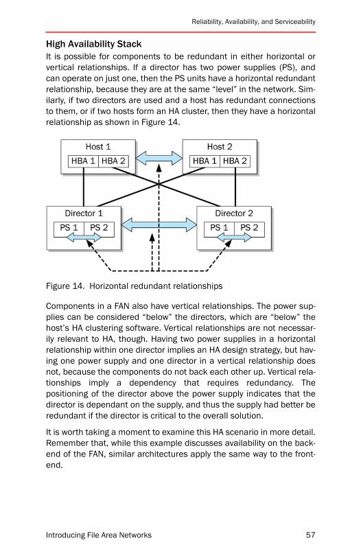
Reliability, Availability, and Serviceability
High Availability StackIt is possible for components to be redundant in either horizontal orvertical relationships. If a director has two power supplies (PS), andcan operate on just one, then the PS units have a horizontal redundantrelationship, because they are at the same “level” in the network. Sim-ilarly, if two directors are used and a host has redundant connectionsto them, or if two hosts form an HA cluster, then they have a horizontalrelationship as shown in Figure 14.
Figure 14. Horizontal redundant relationships
Components in a FAN also have vertical relationships. The power sup-plies can be considered “below” the directors, which are “below” thehost’s HA clustering software. Vertical relationships are not necessar-ily relevant to HA, though. Having two power supplies in a horizontalrelationship within one director implies an HA design strategy, but hav-ing one power supply and one director in a vertical relationship doesnot, because the components do not back each other up. Vertical rela-tionships imply a dependency that requires redundancy. Thepositioning of the director above the power supply indicates that thedirector is dependant on the supply, and thus the supply had better beredundant if the director is critical to the overall solution.
It is worth taking a moment to examine this HA scenario in more detail.Remember that, while this example discusses availability on the back-end of the FAN, similar architectures apply the same way to the front-end.
Introducing File Area Networks 57
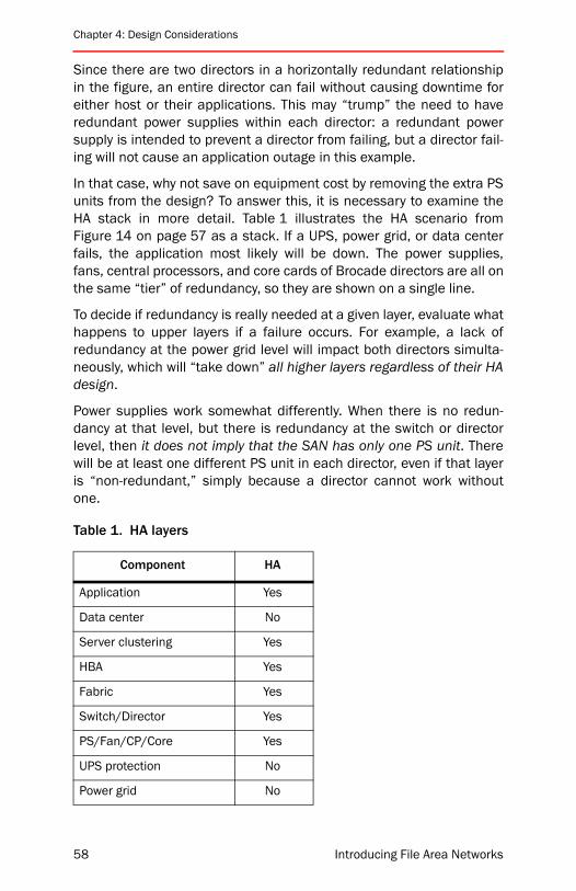
Chapter 4: Design Considerations
Since there are two directors in a horizontally redundant relationshipin the figure, an entire director can fail without causing downtime foreither host or their applications. This may “trump” the need to haveredundant power supplies within each director: a redundant powersupply is intended to prevent a director from failing, but a director fail-ing will not cause an application outage in this example.
In that case, why not save on equipment cost by removing the extra PSunits from the design? To answer this, it is necessary to examine theHA stack in more detail. Table 1 illustrates the HA scenario fromFigure 14 on page 57 as a stack. If a UPS, power grid, or data centerfails, the application most likely will be down. The power supplies,fans, central processors, and core cards of Brocade directors are all onthe same “tier” of redundancy, so they are shown on a single line.
To decide if redundancy is really needed at a given layer, evaluate whathappens to upper layers if a failure occurs. For example, a lack ofredundancy at the power grid level will impact both directors simulta-neously, which will “take down” all higher layers regardless of their HAdesign.
Power supplies work somewhat differently. When there is no redun-dancy at that level, but there is redundancy at the switch or directorlevel, then it does not imply that the SAN has only one PS unit. Therewill be at least one different PS unit in each director, even if that layeris “non-redundant,” simply because a director cannot work withoutone.
Table 1. HA layers
Component HA
Application Yes
Data center No
Server clustering Yes
HBA Yes
Fabric Yes
Switch/Director Yes
PS/Fan/CP/Core Yes
UPS protection No
Power grid No
58 Introducing File Area Networks

Reliability, Availability, and Serviceability
With that in mind, when there is a lack of redundancy at the PS level, afailure there will cause one and only one director to go down. If thathappens in the example shown in Figure 14 on page 57, the entire fab-ric will have failed. If that happens, the HBA attached to that fabric willfail. However, because there are redundant HBAs connected to redun-dant fabrics, no layers above the HBA will be impacted. The failure willhave been “caught” by the multipathing driver which supports theredundant HBAs. But what does that actually mean?
Generally speaking, it means that the application (that is, the networkfile system served by the FAN) will sit idle for some number of secondsor even minutes while time-outs propagate up and down its driverstack, before the failover occurs. When it does switch to the alternatepath, there is risk: a chance that something could go wrong, due toeither a configuration error or a simultaneous failure of any compo-nent in the redundant fabric stack. In the best case, an administrativeaction is likely to be required to fix the SAN, and to switch the hostback to the original fabric once the power supply has been replaced.
To make matters worse, in almost all SANs there will be more than onehost connected to the failing director, which means that a single powersupply failure will impact—to one extent or another—potentially hun-dreds of applications. This magnifies the impact of failover risk (forexample, multipathing configuration errors, and so on) and theamount of effort needed to recover from the event.
Finally, the larger the scope of a failure, the more likely that a simulta-neous failure will render some or all of the HA protection ineffective. Ifan SFP fails on a “Director 2” port attached to a storage array, and asimultaneous failure occurs on a “Director 1” power supply, then allapplications relying on the storage array port will lose both paths totheir data at the same time.
The bottom line is that, the higher up the HA stack a problem getsbefore it is caught, the more complex the solution that finally catchesthe failure is likely to be. Server clustering and multipathing are morecomplex to design and implement than power supply redundancy. Thehigher up the stack an error propagates, the more risk there is that theredundancy mechanism will malfunction, and the more administrativeeffort will be required to remedy the problem even if all goes well. Thenet effect is that, if it is possible to “trap” a problem at the power sup-ply level, then it is best to do, even if it could have been trapped at ahigher level.
Introducing File Area Networks 59
Chapter 4: Design Considerations
This leads to the second major principle of HA theory, which is: Alwaystrap an error as low in the stack as possible.
The reason designers use redundancy at multiple vertical layers (forexample, power supplies and fabrics) is that this method makes itmuch less likely that any given error will result in application down-time, and makes it much easier to recover from any problem at thelower levels in the stack.
So how does this apply to FAN design? Refer to Figure 2 on page 6 andthe bullet list below it. In order to be fully redundant, the FAN musthave redundancy engineered into each and every vertically relatedcomponent between the client and the block storage which containsthe file data. (Note that the figure is rotated sideways to accommodatethey layout of the book, so in this case “vertical” relationships areactually horizontal.) The principle for designers to take away from thisis that HA FAN solutions should use fully redundant designs, with eachredundant component preferably having a resilient internal design. Ifthis is not possible for cost reasons, then the single points of failuremust be documented, and plans must be in place to handle failures asrapidly as possible.
ServiceabilityServiceability is a measure of how easy it is for service personnel toperform their jobs with respect to a particular product or system. Thisis largely a subjective measurement. As with the previous two RASmetrics, serviceability can include hardware, software, solutions, andeven the overall network architecture.
This is an important consideration for designers for two reasons:
• Products with better serviceability tend to cost less to manage onan ongoing basis. For example, if a product is hard to use, moremoney will need to be spent on training, support, or on outsideconsultants.
• Serviceability can affect uptime. Products that can be servicedfaster can recover from outages faster. Also, more complex prod-ucts are more likely subject to human administrator errors.
MTTR can be viewed as a serviceability metric as well as playing a rolein reliability. If a component fails, how long will it take service person-nel to fix it? The smaller the number for MTTR, the faster service wasperformed. This implies better serviceability. FAN designers shouldlook at the MTTR for components such as NAS heads, and block stor-age back-end devices.
60 Introducing File Area Networks

Performance
However, this is not the most important aspect of serviceability, andmost other aspects cannot be described by well-defined statisticalmetrics. For example, many products have built-in diagnostic tools.Simply counting the number of tools would not provide a useful metric,since each tool might have or lack features that affect how easily asystem can be serviced. Doing a thorough evaluation of serviceabilityas part of the approach to component selection requires substantialeffort on the part of the designer. Since serviceability is rarely the topconcern when making a product selection, the time is usually betterspent elsewhere. As a result, many designers use a simpler approachof using other criteria to make component selection decisions.
PerformanceThere are several areas to consider when thinking about performancein a FAN solution, including protocols, end-point behaviors, link rates,congestion, and latency. Trade-offs often need to be made betweenthese and other performance considerations versus cost.
For example, all other things being equal, extending a CIFS file systemover a WAN causes a reduction in performance when compared to run-ning that file system across a LAN. WANs are always slower than LANs,if for no other reason than that the speed of light dictates higherlatency in a WAN. However, the CIFS protocol in particular was notdesigned with WAN performance in mind. In order to achieve accept-able performance, a protocol-aware acceleration technology isrequired. FAN designers attempting to extend file systems acrossWANs therefore tend to deploy WAFS nodes, after analyzing the proto-col-related performance considerations.
Thinking about performance is particularly important when designingDisaster Recovery (DR) solutions. (This general category includesbackup/restore as well for the purposes of this book.) In particular,designers should consider how much time it will take to recover fromvarious different outage scenarios. This is another reason why adesigner might choose one FAN technology over another.
The designer should keep performance in mind when evaluating anycandidate design, and pick the FAN tools best suited to solving theproblem at hand. Be sure to make decisions that can support the per-formance requirements of the initial deployment, and all anticipatedfuture increases in performance demand. Network performancerequirements tend to increase rather than decrease over time, and soall protocol and topology choices should be able to accommodate awide range of performance scenarios.
Introducing File Area Networks 61
Chapter 4: Design Considerations
ScalabilityScalability can mean quite a few different things in the context of filenetworking. For example, it can be a measure of how much data a par-ticular NAS product accommodates. (A NAS box is may be consideredmore scalable than another one because the drive cabinet is largerand therefore it can accept more disks.)
However, in the context of FAN infrastructure design, it usually refers totwo things:
• How many clients are supportable?
• How much total file data can be added before the network needsto be restructured?
(A network design may be considered more scalable than anotherone because each Brocade StorageX server has more CPU powerand can therefore support more clients.)
In theory, a Brocade FAN solution should be infinitely scalable. How-ever, many real-world considerations can cause lower scalability as apractical matter. For example, a FAN design might hit a level at whichthe IT team cannot deploy WAFS nodes fast enough to meet userdemand. While that example does not illustrate a fundamental scal-ability issue with WAFS, it does illustrate a practical scalability limit ofdeploying WAFS with limited IT resources.
Designing a FAN to scale to the largest size it could be expected toneed to grow to in a reasonable time frame is always more practicalthan merely meeting the target requirements at the time of implemen-tation. This prevents the FAN from being “painted into a corner” andneeding to be fundamentally restructured after entering production.Because of this, designers must consider scalability carefully whendeciding on a top-level architecture.
62 Introducing File Area Networks

Total Solution Cost
Total Solution CostIT departments no longer have unlimited budgets, if indeed they everdid, so it is necessary for FANs to be implemented in a cost-effectivemanner. The job of the designer should be to consider the total cost ofa solution, rather than looking only at a limited subset of the cost.
For example, some approaches to FAN design might save on hardwarecost, but offset that savings with an even larger increase in cost to thebusiness from downtime. Using non-HA design strategies is an exam-ple of this. Before deploying a non-redundant solution to save on cost,be sure to consider the long-term impact of downtime to the attachedsystems. Consider what the cost would be if a non-redundant designwere used to support a DR solution, and it failed during a disaster andprevented restoration of business services. Even one incident like thisin a large-scale operation would more than cover the entire cost ofdeploying several redundant FANs.
In most cases, designers have found that cutting corners on infrastruc-ture to save short-term cost tends to increase the total cost ofownership. Even when cost is a key requirement for the design team,you need to look at all cost components, not just at any one compo-nent. Keep this in mind when evaluating network topologies and top-level HA architectures.
WANAs with other network design problems, the first step in designing along-distance FAN is to figure out its requirements. In general, adesigner needs to collect requirements such as:
• Distance to be supported by each link
• Speed
• Reliability and availability
• Security requirements
The remainder of this section discusses some of these considerationswhen you are evaluating specific long-distance design problems.
Introducing File Area Networks 63
Chapter 4: Design Considerations
General Distance ConsiderationsAvailability of WAN resources. Can the FAN requirements be met withthe WAN resources already in place? How will that impact the existingusage of the network? Will the WAN be able to support peak usage,such as during a restore operation?
Budget vs. value of data. It will cost money to implement an effectivesolution. How does this cost compare to the potential loss of data andapplication availability if a disaster strikes? If a solution is less expen-sive to implement initially, will it be less expensive to maintain overtime? Running CIFS over a WAN without an accelerator will be lessexpensive initially, but will also be harder to manage and troubleshooton an ongoing basis.
Which MAN/WAN technology to use depends on a number of factors,such as:
Availability of Service. Is there a provider that can deliver service ateach site? For example, if dark fiber is not available between sites,then another technology will need to be used no matter how well darkfiber otherwise would have met the requirements.
Application RAS Requirements. For applications that require high reli-ability, availability, and serviceability, any of the technologies could beemployed provided that appropriate Service Level Agreements (SLAs)are in place and only enterprise-class components are used.
Application Performance Requirements. Many applications are sensi-tive to delay and error rates on their storage devices, while others areless so. Performance on hosts running synchronous mirrors over dis-tance will be severely degraded unless WAN performance is best-in-class, whereas asynchronous mirroring applications can usually toler-ate more delay and a higher error rate.
Distance Between Sites. Some technologies are inherently limited toMAN and shorter WAN distances, such as dark fiber and xWDMs. Oth-ers can support long distances, but not without incurring delay andloss that may impact applications. SONET/SDH and ATM tend to begood fits for very long distances.
Solution Cost. How much does each service option and network infra-structure cost, both initially and on an ongoing basis? For example, ifyou have an application that would benefit from SONET/SDH, but onlyhave half the budget necessary to deploy it, another solution is proba-bly more appropriate.
64 Introducing File Area Networks
WAN
Data Migration ConsiderationsIn most cases, when you are planning data migration, the data beingmoved is not “live” at the time of its movement. If it is live, it is beingserved by a local mirror copy while it is being replicated to a remotesite. Because of this, data migration tends to be tolerant of failures,performance issues, and errors compared to other extension solu-tions. The main factors to consider are how long the migration isallowed to take and how well the production environment is insulatedfrom the migration project. For narrower migration windows, BrocadeStorageX can be used to accelerate the process by moving most of thedata before the “window” needs to be opened. Other FAN products canhelp in similar ways.
Disaster Recovery ConsiderationsFor distance extension solutions intended to solve DR or similar prob-lems, the following points should be considered during the planningprocess.
Application critically. Which file systems require protection? Criticalfile systems should be protected with fully redundant HA architectures.
Acceptable recovery time. The maximum time an application can beunavailable. Decide the best mechanism for fast recovery in each sce-nario. If the data set at the primary location is corrupted, will you copythe data back over the WAN and restore the application at the primarysite, or will you use a standby server at the recovery location? For sce-narios in which you need to copy data over the WAN, you need tocalculate how much time the copy can take. The performance of theinfrastructure between sites will need to support this. As with datamigration, Brocade StorageX and other FAN applications can help toaccelerate this.
Acceptable data loss. How much data can be generated at the pri-mary data center before it is copied to a remote site? In the event of adisaster or even small-scale failure at the primary data center, anydata not copied to the remote site will be lost. This may dictate a syn-chronous versus an asynchronous solution. If the application cannottolerate any data loss at all, synchronous solutions are needed. This inturn dictates a high-performance inter-site transport, such as FibreChannel, xWDM, or SONET/SDH.
Introducing File Area Networks 65

Chapter 4: Design Considerations
Location. The distance between data centers should be great enoughso that at least one site will survive an anticipated disaster (threatradius considerations). The distance between sites may dictate tech-nological options for the WAN. For example, if the sites are locatedhalfway around the globe, WAFS over IP may be a viable option,whereas FC SAN extension might not work at all. If they are located afew hundred kilometers apart, then native FC or xWDM could be a bet-ter choice.
Testing. The DR strategy must be routinely tested, or it may not workwhen needed. Before implementation, decide what testing is needed,and how and when the tests will be carried out. It is also important toevaluate how testing will affect production operations.
Implementation and BeyondOnce the design is complete, in many cases the job of the designer willbe over. In most large-scale environments, the jobs of designer, imple-mented, and manager will be distinct. However, there are areas inwhich the designer can either facilitate or hinder subsequent tasks.FAN designers should consider how the solution will be installed andmanaged on a day-to-day basis. Indeed, FANs are often deployed spe-cifically because they can improve management tasks. Thesegenerally include monitoring the health of the network, and performingadds, moves, and changes to the FAN itself and to the attacheddevices. It may be useful for the designer to work with whatever per-sonnel will end up managing the FAN and its component parts to plana maintenance strategy, listing all day-to-day tasks and determining inadvance how the FAN will affect these tasks.
The following section discusses some of the items related to imple-mentation you should keep in mind while creating a design, and thatmay need to be included in the project planning documentation.
Rack Locations and MountingBefore committing to a specific design, make sure that suitable loca-tions exist for new equipment. This means making sure that the rightkinds of racks are available, and that their locations are appropriate.
Different devices have different rack heights, depths, structural integ-rity needs, weights, and even widths. For obvious reasons, it isimportant to ensure that the racks intended for mounting the equip-ment have the same characteristics as the equipment to be mounted.This may require purchasing new racks, lifts, or cabinets specificallyfor the project.
66 Introducing File Area Networks
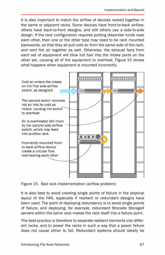
Implementation and Beyond
It is also important to match the airflow of devices racked together inthe same or adjacent racks. Some devices have front-to-back airflow;others have back-to-front designs, and still others use a side-to-sidedesign. If the rack configuration requires putting dissimilar kinds neareach other, then one or the other type may need to be rack mountedbackwards, so that they all pull cold air from the same side of the rack,and vent hot air together as well. Otherwise, the exhaust fans fromeach set of equipment will blow hot hair into the intake ports on theother set, causing all of the equipment to overheat. Figure 15 showswhat happens when equipment is mounted incorrectly.
Figure 15. Bad rack implementation (airflow problem)
It is also best to avoid creating single points of failure in the physicallayout of the FAN, especially if resilient or redundant designs havebeen used. The point of deploying redundancy is to avoid single pointsof failure, and deploying, for example, redundant Brocade StorageXservers within the same rack makes the rack itself into a failure point.
The best-practice is therefore to separate resilient elements into differ-ent racks, and to power the racks in such a way that a power failuredoes not cause either to fail. Redundant systems should ideally be
Introducing File Area Networks 67

Chapter 4: Design Considerations
located in entirely different rooms. The degree of separation thatwould be recommended depends on a number of factors, such as thesize of the FAN, the difficulty of cabling to different areas, the impactto the organization of a failure to the entire FAN at the same time, andso on. It comes down to balancing the risk of a simultaneous failurecaused, for example, by a fire suppression system going off overhead,versus the cost of distributing the components to different locations.
The designer should ensure that the racks targeted for equipmentmounting:
• Physically accommodate the equipment
• Support the HA architecture of the FAN
• Provide correct airflow to cool the equipment
Power and UPSsWhen designing a FAN with availability in mind, it is important that theduality be employed throughout the network design and the implemen-tation. For HA designs, ensure that the data center has separate powerinputs available, and that redundant components are connected to dif-ferent power supply units and power grids.
Staging and ValidationPrior to transitioning a FAN solution to production, it is important to val-idate that the solution really works. The best way to do this is to build itin a separate environment, usually called a “staging configuration,”and run tests over it to ensure that it satisfies performance and avail-ability expectations.
Once the FAN products are staged, the implementation team will needto inject faults into the system to verify that the FAN itself and allrelated devices are capable of recovering. The next step involves gen-erating an I/O load that approximates anticipated application I/Oprofiles. Finally, the team will want to run an I/O load while also inject-ing faults to approximate a worst-case scenario, that is, a failure in theFAN while it is in production.
The designer is rarely responsible for personally executing this processin a large-scale environment. However, the designer will be in a goodposition to tell the implementation team how to design the I/O profilethat will run across the network(s), and what kinds of faults areexpected to be recoverable.
68 Introducing File Area Networks
Implementation and Beyond
Release to ProductionBroadly, there are two categories of rollout for FANs:
• “Green field” deployments, where the file network is built from theground up
• Installed base upgrades, where existing file servers are enhancedby adding new software and equipment
Green Field RolloutThis is the easiest scenario to discuss, since there is no risk to produc-tion applications during the rollout phase. For most, the sequence fora green field rollout is as follows:
1. Create a design and documentation set.
2. Create a high-level rollout plan, describing the phases below andgiving schedule targets for each.
3. Source and acquire equipment and software. This may be done allat once, or in a phased manner.
4. Begin to deploy and test the FAN. Build out the core infrastructurefirst, so that the overall structure of the network does not need tokeep changing during the rollout.
Installed Base Upgrade RolloutMost FAN deployments seem to fall into this category. Adding new net-work equipment to an existing environment can be as simple asplugging it in and turning it on, or as complex as building a dedicatedtest environment and running months of stress tests prior to produc-tion use. It depends on site-specific change control procedures, thedegree of confidence the network administrators have in the newequipment, and the impact to the company that would result from afailure during the rollout.
For sites with extremely tightly controlled environments, release to pro-duction may resemble a green field deployment: the new solutioncould be built in an isolated environment and production applicationsmigrated over to it only once it was proven to be stable.
Introducing File Area Networks 69

Chapter 4: Design Considerations
Day-to-Day ManagementThere are a number of ways in which the designer can simplify ongoingmanagement tasks. For example, using a redundant and resilientarchitecture simplifies upgrading to newer technologies, which willinevitably be adopted over time. Also, as part of the design and imple-mentation processes, the designer should create a documentrepository. If the design is well-documented, and maintenance proce-dures are created during the process, management will be easier lateron.
The designer should create a configuration log, which explains how theFAN is configured and why it was configured that way. It should serveas a record for change management processes: if a change is madeand something stops working, the administrator can refer back to thislog to find out what changed and why. The designer should ensure thatprocedures require administrators to update the log wheneverchanges are made to existing configurations or if switches are addedor removed.
Planning for TroubleshootingLike all other networking technologies, from time to time it will be nec-essary to troubleshoot a FAN, and like any other network, this processmeans finding out which piece of hardware, software, or configurationis malfunctioning. The designer is rarely responsible for performingtroubleshooting, but there are ways in which the designer can simplifythe process.
For example, it is generally easier to troubleshoot a small network thana large one. If the designer chooses a hierarchical design in which theFAN is broken up into smaller “mini-FAN” solutions, then failures willbe contained within a smaller area. This makes it less likely that therewill be trouble later on, as well as making it easier to figure out whatwent wrong if something does go awry.
Similarly, it is easier to troubleshoot FANs that limit the number of FANproduct interactions. If the solution uses Brocade StorageX, thenstacking FLM, WAFS, and MyView on top of it might not be easy todebug. At least initially, it would be desirable to pick one FAN applica-tion and get that working before rolling out more.
70 Introducing File Area Networks

Chapter Summary
Chapter SummaryIt is never possible to dictate laws of design for complex networkingsolutions, and this chapter should not be taken as an attempt to do so.Each deployment will have unique requirements, and unique valua-tions for resolving conflicting requirements. You should review this andother data center literature, but also consult with the designers whowork for your support provider for insight into the best solution for yourrequirements and environment.
Introducing File Area Networks 71

Chapter 4: Design Considerations
72 Introducing File Area Networks
Introducing File Area Networks
5
Brocade StorageXBrocade StorageX is designed to solve a variety of real-world IT man-agement problems. “Chapter 3: Building Blocks” starting on page 31discusses the product at a high level. This chapter provides moredetailed information about the product architecture, as well as provid-ing real-world advice on deployment and management in the followingsections:
• “Deployment Examples” on page 75
• “Product Architecture” on page 82
• “Data Migration Tasks” on page 98
• “Data Migration Methods” on page 99
• “StorageX and NetApp Storage Device Integration” on page 104
• “Troubleshooting” on page 109
• “Chapter Summary” on page 111
Windows and UNIX environments both have operational challengeswhere file management is concerned. StorageX is designed to alleviatemany of these. For example, in a Windows environment, StorageXhelps mitigate or eliminate entirely these persistent managementproblems:
• To retrieve files, users must know the physical location of the data.
• Mapping a single drive letter to an individual share scales poorly.
• Limitations on the capacity and performance of storage devicesare created.
• Limits the amount of data that can be stored inside a single shareor mount point.
73

Chapter 5: Brocade StorageX
• User group data is spread across multiple shares, servers, andlocations to accommodate size and access needs.
• User training is required from both administrators and co-workersabout configurations and changes.
• Users are required to make concessions for administratorsbecause of the lack of transparency during server issues,upgrades, or moves.
• Administrators must manage complex logon scripts to providemultiple drive mappings based on client needs.
• Administrators must change user objects to reflect changes touser home directories.
• Administrators must balance the downside of backup and restoreissues related to volume size versus the downside of changing theuser environment.
• Administrators must justify the introduction of new technologybased on its benefits with the added cost of impacting the usercommunity.
• Administrators must complete migrations on the weekend or afterhours to limit the disruption to users.
Brocade StorageX is an open, standards-based software platform thatcan be seamlessly and non-disruptively introduced into an IT infra-structure. The software runs on any industry-standard server runningMicrosoft Windows 2000 or later, and does not require the deploy-ment of a new hardware device. Because it is not in the data path,StorageX does not introduce any performance or latency issues whenused to create and manage the GNS. It uses existing file systems,which means that administrators are not required to change their net-work operating procedures to enjoy the benefits of StorageX.
StorageX also integrates with the existing network security frameworkand administrators can use security settings such as group permis-sions to automatically create and populate a GNS. No software oragents are required on the client machines accessing the namespace;and unlike many GNS solutions, StorageX does not require the intro-duction of a new protocol on the network.
74 Introducing File Area Networks

Deployment Examples
Deployment ExamplesThis section illustrates some of the more popular use cases scenariosfor Brocade StorageX— the problem faced by users or administratorsand then how StorageX could be deployed to solve the problem.
Single User Drive Mapping ProliferationWindows clients typically map drive letters to network shares based onthe physical location of the data. UNIX clients have a similar mecha-nism using mount points. Each file server or NAS appliance gets itsown drive letter on each PC. Users are often confused about whichdrive contains a particular file, and needlessly waste productivitycycles searching for their data, as shown in Figure 16.
Figure 16. Too many drive mappings
Introducing File Area Networks 75
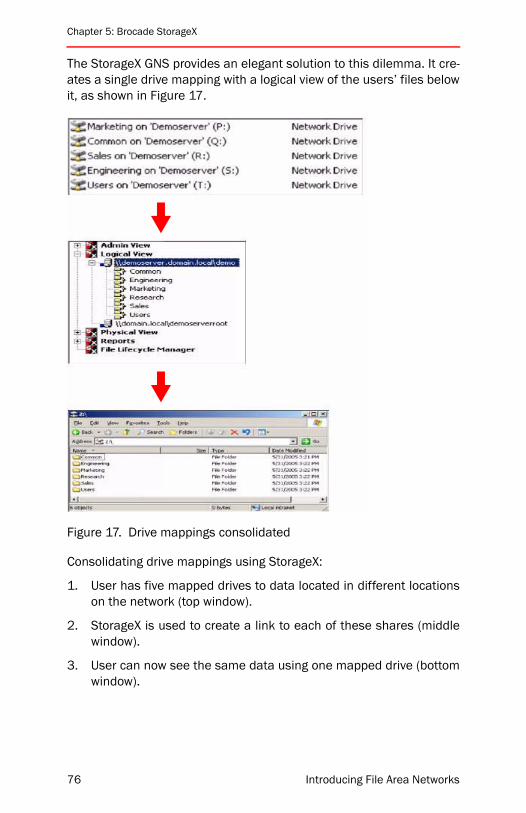
Chapter 5: Brocade StorageX
The StorageX GNS provides an elegant solution to this dilemma. It cre-ates a single drive mapping with a logical view of the users’ files belowit, as shown in Figure 17.
Figure 17. Drive mappings consolidated
Consolidating drive mappings using StorageX:
1. User has five mapped drives to data located in different locationson the network (top window).
2. StorageX is used to create a link to each of these shares (middlewindow).
3. User can now see the same data using one mapped drive (bottomwindow).
76 Introducing File Area Networks

Deployment Examples
Multi-Department Drive Mapping InconsistencyWithout using a GNS, different departments usually have drive lettersmapped differently. This can create confusion when IT personnel areattempting to troubleshoot issues. If an engineering user calls the helpdesk and says that there is a problem with the “E:” drive, that user willbe referring to something radically different than a marketing user whologged exactly the same problem statement with the help desk. This isillustrated in Figure 18.
Figure 18. Inconsistent mappings
Without StorageX, it might be difficult to solve this problem. Indeed, itmight be impossible, since there are only 26 letters in the alphabetand there could be many more than 26 required drive mappings.
With StorageX, the solution is simple. By using a GNS, the view of thewhole environment from the perspective of the end user can be con-solidated under one mapped drive, and this drive letter can be thesame for all departments. The differences in view are at the file/folderlevel, and are centrally managed by IT. If a user calls in with an E: driveproblem, it means the same thing no matter what department they arein. IT can then easily determine whether the issue is with the entire E:
Introducing File Area Networks 77
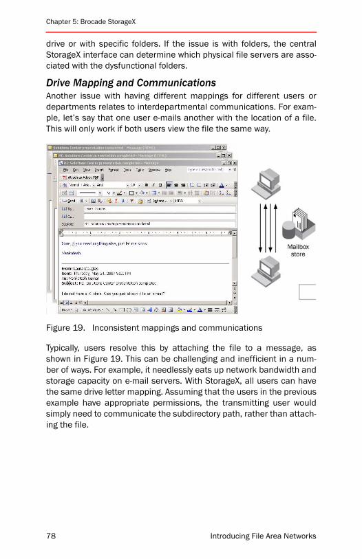
Chapter 5: Brocade StorageX
drive or with specific folders. If the issue is with folders, the centralStorageX interface can determine which physical file servers are asso-ciated with the dysfunctional folders.
Drive Mapping and CommunicationsAnother issue with having different mappings for different users ordepartments relates to interdepartmental communications. For exam-ple, let’s say that one user e-mails another with the location of a file.This will only work if both users view the file the same way.
Figure 19. Inconsistent mappings and communications
Typically, users resolve this by attaching the file to a message, asshown in Figure 19. This can be challenging and inefficient in a num-ber of ways. For example, it needlessly eats up network bandwidth andstorage capacity on e-mail servers. With StorageX, all users can havethe same drive letter mapping. Assuming that the users in the previousexample have appropriate permissions, the transmitting user wouldsimply need to communicate the subdirectory path, rather than attach-ing the file.
78 Introducing File Area Networks

Deployment Examples
Infrastructure ChangesIf drive letter mappings or UNIX mount points are tied to a physicallocation and that location changes, then each and every client willneed to be updated. This can occur, for example, when a storageserver is upgraded to a higher-capacity system.
Figure 20. Migrating to higher-capacity storage
StorageX solves this problem by creating a replica of the data on anew, larger volume and then changing the link to point to the new copyof the data. Using the StorageX Expand command creates a new linkunder the top-level link automatically. StorageX moves the data andredirects users to the new location, and there is no need to reconfig-ure a single client.
Storage OptimizationStorageX can be used to optimize capacity utilization across the GNS.In the scenario shown in the figure below, in which there is a GNS man-aging marketing and sales data. There are four physical devicesstoring the data at varying degrees of utilization. In the Marketing pool,Mktg 1 is running at 98% capacity, while Mktg 2 and Mktg 3 are eachunder 5%. Figure 21 shows what the environment would look like afterStorageX is used to optimize these resources.
Introducing File Area Networks 79

Chapter 5: Brocade StorageX
Figure 21. Optimizing capacity utilization with StorageX
The administrator can use the load balancing policy within StorageX toautomatically detect capacity levels. When StorageX detects the imbal-ance, it can migrate folders away from Mktg 1 and distribute themacross Mktg 2 and Mktg 3. Because the GNS is automatically updatedto reflect the new file locations, this entire process is seamless andnon-disruptive to the end users accessing the folders.
When a user clicks on a folder that was migrated off Mktg 1 onto oneof the other devices, he or she is automatically redirected to the newfile location without knowing it has been moved.
Similarly, the load balancing policy can be used to seamlessly expandthe physical storage devices in a pool. In the example above, theSales 1 device is running at 84% capacity. Using StorageX, the admin-istrator can add Sales 2, and automatically balance the Sales foldersacross the two devices without disrupting end user access to theirdata.
80 Introducing File Area Networks

Deployment Examples
Some of the benefits of capacity balancing are:
• Automated, policy-based setup and execution of load balancingallows for unattended storage optimization.
• The GNS is automatically updated to reflect the data migration, sothat it is transparent to the end user.
• Multiple policy settings allow administrators flexibility in choosingcapacity thresholds for storage devices.
Data Lifecycle ManagementData lifecycle management solutions solve budgetary problems withinIT. StorageX can be used to create a tiered storage architecture toautomate this category of solution. Policies can be scheduled to auto-matically migrate files as shown in Figure 22.
Figure 22. Data lifecycle management concept
When files are migrated based on administrator-defined criteria suchas last access time or age, the GNS is automatically updated to reflectthe new location of the files. When users access a file after it has beenmoved, the GNS automatically sends them to the new location.
Introducing File Area Networks 81

Chapter 5: Brocade StorageX
By using the data lifecycle management features of StorageX, adminis-trators can reduce the overall cost of storage by placing critical data onpremium storage devices, and as data becomes less critical to theorganization, automatically moving it to less expensive storagedevices.
Product ArchitectureStorageX is a robust set of applications built on the GNS that can unifyheterogeneous storage devices and provide consistent data services,regardless of the underlying hardware. Figure 23 shows the primaryapplications for StorageX in different areas of the IT infrastructure.
Figure 23. StorageX applications
StorageX can be used to deliver replication, migration, consolidation,and failover and lifecycle management services across the enterprise--spanning remote sites, data centers and DR sites. The product archi-tecture is highly scalable and flexible, and solves a wide variety ofproblems related to single data center activities, branch office admin-istration, and disaster recovery sites.
This section discusses the components of StorageX, and some of theelements of its architecture that allow it to provide those functions.
82 Introducing File Area Networks
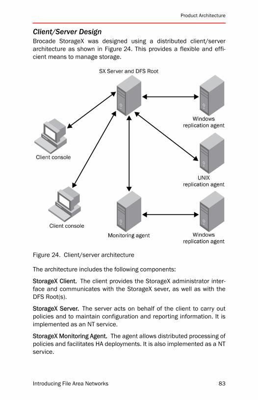
Product Architecture
Client/Server DesignBrocade StorageX was designed using a distributed client/serverarchitecture as shown in Figure 24. This provides a flexible and effi-cient means to manage storage.
Figure 24. Client/server architecture
The architecture includes the following components:
StorageX Client. The client provides the StorageX administrator inter-face and communicates with the StorageX sever, as well as with theDFS Root(s).
StorageX Server. The server acts on behalf of the client to carry outpolicies and to maintain configuration and reporting information. It isimplemented as an NT service.
StorageX Monitoring Agent. The agent allows distributed processing ofpolicies and facilitates HA deployments. It is also implemented as a NTservice.
Introducing File Area Networks 83

Chapter 5: Brocade StorageX
StorageX Replication Agent. The agent carries out file transfers forStorageX policies. StorageX provides Windows and UNIX replicationsagents.
Data migration and consolidation are two of the innovative features ofBrocade StorageX. Migration and consolidation are no longer point-in-time IT projects for administrators. Rapid changes in hardware, tech-nology, and capacity demands are forcing enterprises to implementongoing migration strategies to optimize available assets. However,consolidation presents many challenges for IT administrators. Theseinclude: minimizing client downtime, supporting ongoing data migra-tion practices with minimal IT resources, consolidating data in aheterogeneous environment, and maximizing Return On Investment(ROI) by effectively utilizing storage resources across the enterprise.
The key feature of the StorageX implementation is its use of a globalnamespace. Using a GNS to facilitate data migration can result in sig-nificant time and cost savings. IT administrators who need to migratefrom Windows NT 4 to Windows 2000/2003; Novell to Windows; Linuxto Solaris; or Windows or UNIX file storage to NAS, should considerdeploying a GNS to facilitate the migration. It creates a virtual pool ofstorage and enables administrators to readily identify migrationrequirements across platforms. The concept and benefits of GNS isfurther discussed in “Chapter 1: FAN Basics” starting on page 1.
GNS DeploymentBrocade StorageX provides administrators with reusable policies thatcontrol key data management and data movement activities. Policiesare a key component of the StorageX architecture, as they save consid-erable time in implementing a GNS, and also simplify ongoingmanagement tasks. Policies for initial deployment of the GNS are con-veniently managed using the StorageX Namespace Creation Wizard,as shown in Figure 25. Similarly intuitive interfaces are provides formanaging other policies on an ongoing basis.
84 Introducing File Area Networks
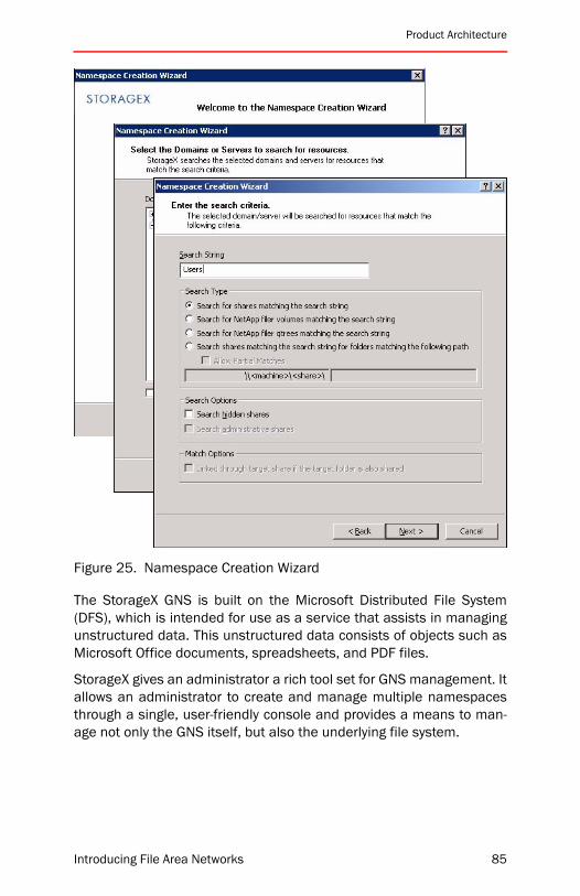
Product Architecture
Figure 25. Namespace Creation Wizard
The StorageX GNS is built on the Microsoft Distributed File System(DFS), which is intended for use as a service that assists in managingunstructured data. This unstructured data consists of objects such asMicrosoft Office documents, spreadsheets, and PDF files.
StorageX gives an administrator a rich tool set for GNS management. Itallows an administrator to create and manage multiple namespacesthrough a single, user-friendly console and provides a means to man-age not only the GNS itself, but also the underlying file system.
Introducing File Area Networks 85
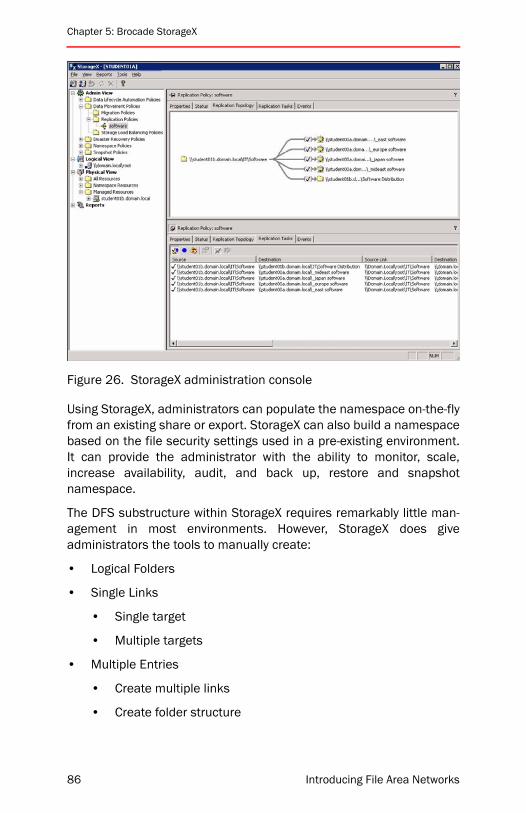
Chapter 5: Brocade StorageX
Figure 26. StorageX administration console
Using StorageX, administrators can populate the namespace on-the-flyfrom an existing share or export. StorageX can also build a namespacebased on the file security settings used in a pre-existing environment.It can provide the administrator with the ability to monitor, scale,increase availability, audit, and back up, restore and snapshotnamespace.
The DFS substructure within StorageX requires remarkably little man-agement in most environments. However, StorageX does giveadministrators the tools to manually create:
• Logical Folders
• Single Links
• Single target
• Multiple targets
• Multiple Entries
• Create multiple links
• Create folder structure
86 Introducing File Area Networks

Product Architecture
Figure 27. Creating a DFS structure
Replication TechnologyReplication technologies are mature in the marketplace, and it is com-mon to see vendors of traditional replication solutions repackagingtheir products to fit the current needs of the enterprise. However, manyof the technologies were designed for specific applications and infra-structures that have evolved considerably since the introduction of thereplication solution. Brocade StorageX Byte-Level File Differential Rep-lication (BFDR) is designed specifically to address the current dataprotection priorities of the enterprise, so it is not a repackaged toolwith historical roots.
Various replication technologies are suited for specific business appli-cations storage platforms and network infrastructures. For example,databases and mission-critical data require real-time protection (that
Introducing File Area Networks 87
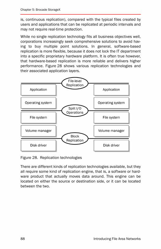
Chapter 5: Brocade StorageX
is, continuous replication), compared with the typical files created byusers and applications that can be replicated at periodic intervals andmay not require real-time protection.
While no single replication technology fits all business objectives well,corporations increasingly seek comprehensive solutions to avoid hav-ing to buy multiple point solutions. In general, software-basedreplication is more flexible, because it does not lock the IT departmentinto a specific proprietary hardware platform. It is often true however,that hardware-based replication is more reliable and delivers higherperformance. Figure 28 shows various replication technologies andtheir associated application layers.
Figure 28. Replication technologies
There are different kinds of replication technologies available, but theyall require some kind of replication engine, that is, a software or hard-ware product that actually moves data around. This engine can belocated on either the source or destination side, or it can be locatedbetween the two.
88 Introducing File Area Networks

Product Architecture
Figure 29. Replication engine locations
StorageX can be deployed using any of these models; it offers twotypes of replication:
• File-level replication
• Byte-level replication
Introducing File Area Networks 89
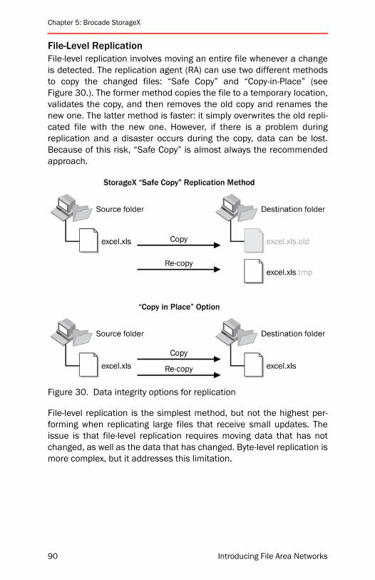
Chapter 5: Brocade StorageX
File-Level ReplicationFile-level replication involves moving an entire file whenever a changeis detected. The replication agent (RA) can use two different methodsto copy the changed files: “Safe Copy” and “Copy-in-Place” (seeFigure 30.). The former method copies the file to a temporary location,validates the copy, and then removes the old copy and renames thenew one. The latter method is faster: it simply overwrites the old repli-cated file with the new one. However, if there is a problem duringreplication and a disaster occurs during the copy, data can be lost.Because of this risk, “Safe Copy” is almost always the recommendedapproach.
Figure 30. Data integrity options for replication
File-level replication is the simplest method, but not the highest per-forming when replicating large files that receive small updates. Theissue is that file-level replication requires moving data that has notchanged, as well as the data that has changed. Byte-level replication ismore complex, but it addresses this limitation.
90 Introducing File Area Networks
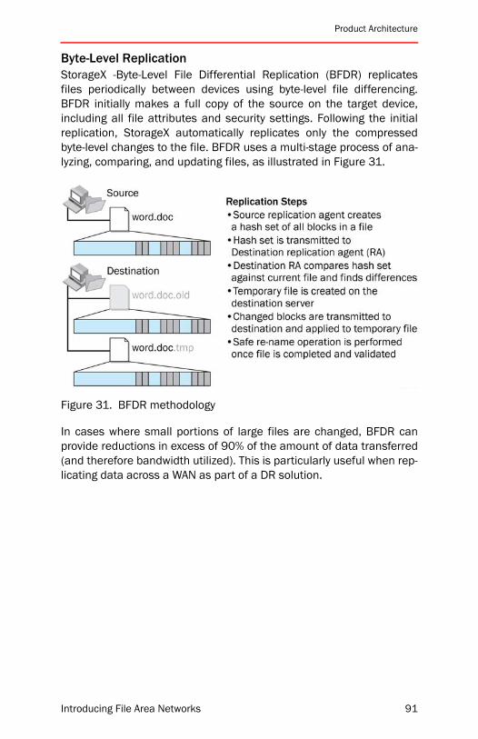
Product Architecture
Byte-Level ReplicationStorageX -Byte-Level File Differential Replication (BFDR) replicatesfiles periodically between devices using byte-level file differencing.BFDR initially makes a full copy of the source on the target device,including all file attributes and security settings. Following the initialreplication, StorageX automatically replicates only the compressedbyte-level changes to the file. BFDR uses a multi-stage process of ana-lyzing, comparing, and updating files, as illustrated in Figure 31.
Figure 31. BFDR methodology
In cases where small portions of large files are changed, BFDR canprovide reductions in excess of 90% of the amount of data transferred(and therefore bandwidth utilized). This is particularly useful when rep-licating data across a WAN as part of a DR solution.
Introducing File Area Networks 91
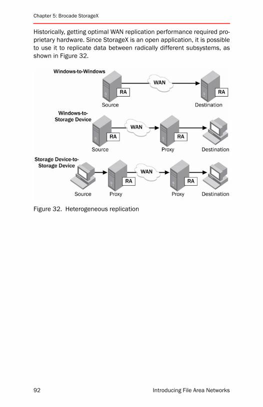
Chapter 5: Brocade StorageX
Historically, getting optimal WAN replication performance required pro-prietary hardware. Since StorageX is an open application, it is possibleto use it to replicate data between radically different subsystems, asshown in Figure 32.
Figure 32. Heterogeneous replication
92 Introducing File Area Networks

Product Architecture
Replication ManagementManaging replication is largely automated within Brocade StorageX.During initial setup, an administrator configures the replicationrequirements by using the console. StorageX provides administratorswith control over aspects and attributes such as security, bandwidth,scheduling, and replication protocol (file or byte-level file differencing),among others. The overall architecture of replication management isshown in Figure 33.
Using StorageX, administrators can:
• Run reports detailing status and configuration
• View reports detailing status and configuration
• View event logs showing history of operations
Figure 33. Managing replication
Introducing File Area Networks 93
Chapter 5: Brocade StorageX
The replication manager maintains configuration information in itsdata store and is responsible for the ongoing evaluation of storage pol-icies. At scheduled intervals configured in the policy, the serverinitiates transfers and assigns them to the replication agent for pro-cessing. Based on policy configuration, the server also invokes user-provided scripts for custom processing operations upon initiating thetransfer. The StorageX replication agent carries out the transfer,reporting back status and results to the replication manager, whichthen makes this information available in the StorageX console.
In carrying out the operation, the replication agent:
• Validates the source and destination
• Determines the files or file changes to be sent
• Scans for potential problems and reports if necessary
• Performs the transfer operation as directed
• Retries operations as needed if it encounters errors
• Reports results and statistics to the StorageX server
Brocade StorageX can fail over between multiple sites within minutes,as compared to hours or days typical with other replication products.This is possible due to the seamless integration of BFDR with GNS.
94 Introducing File Area Networks

Product Architecture
Optimizing ReplicationReplication can be optimized for performance (speed) or security (dataintegrity). Table 2 shows parameters that can be modified within Stor-ageX and their impact on replication optimization.
In most environments, it is desirable to optimize for security. It is rarelydesirable to replicate a file quickly but incorrectly. However, there areoccasions when speed may be paramount, and administrators canuse these settings to speed replication processes if necessary.
Brocade StorageX can use the NTFS Change Journal to determinewhich files are to be replicated rather than scanning the entire sourceto detect changes. This is another way of optimizing performance, andhas no security-related downside. Of course, this works only on NTFSfile systems, but it does offer time savings when you need to replicatelarge directory trees with limited changes scattered throughout thedirectory hierarchy.
Table 2. Optimizing replication for performance or security
Optimize for speed Optimize for security
Copy-in-place is enabled Copy-in-place is disabled
“Retry failed file opens…” is disabled
“Retry failed file opens…” is set to default when default is not zero
“Abort if no file is successfully opened…” is disabled
“Abort if no file is successfully opened…” set to default when non-zero
“Event Details set to “Don’t list files” “Event Details set to “List only files with errors”
“Delete orphaned files in destination folders” is disabled
“Delete orphaned files in destination folders” is enabled
“Preserve last access time” is disabled“
Preserve last access time” is enabled
“Allow loss of additional file streams” is disabled
“Copy security descriptor” is set to “Every time the file or folder is copied”
Introducing File Area Networks 95
Chapter 5: Brocade StorageX
Snapshots are another performance enhancing feature without secu-rity risk. StorageX takes a snapshot or makes shadow copies of thevolume in which the source data is located, and then uses the snap-shot as the source. Doing this reduces the possibility of not being ableto transfer source files that are held open for exclusive access by anexternal application at the time of replication. Without using snap-shots, StorageX would have to retry the file or give up on replicating it.
When copying files without snapshots, administrators have the choiceto select on of the following options:
Retry failed file opens x times at y second intervals. Set how manytimes and how often (in seconds) StorageX should attempt to open adestination file.
Abort if file is not successfully opened in x minutes. If files cannot beopened within a specified time, automatically stop the replicationprocess.
Replication CleanupWhen a file is deleted from primary storage, there must be a mecha-nism to remove the file from the replicated copy. However, it is notusually desirable to have this be an automatic mechanism. For exam-ple, a network-bourn virus might attack a network file system bydeleting all of its files. It would not be helpful to have a replicationengine propagate that malicious behavior by automatically deletingthe files from the replicated copy. StorageX provides the “deleteorphaned files on destination folder” option. Running this manuallyensures that the source and destination have identical data, withoutallowing rogue processes to perform similar actions without adminis-trator consent.
96 Introducing File Area Networks
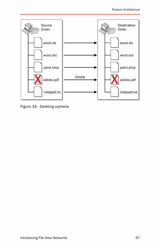
Product Architecture
Figure 34. Deleting orphans
Introducing File Area Networks 97
Chapter 5: Brocade StorageX
Data Migration TasksBrocade StorageX migration usually involves the following tasks:
Create a baseline copy of the source data.
Create incremental copies of changed data.
Connect the users to the migrated data on the destination serv-ers. This is accomplished by simply updating the links to point tothe destination shares as long as the users are already accessingthe GNS.
Back up the source data.
Rename of all the shares on the old source servers so users can-not get to them.
A final replication from the renamed old source server shares tothe destination shares.
Stop sharing the shares on the old servers that have beenmigrated.
Wait for and handle any user access issues. Once confidence ishigh that access for the users is robust, then delete the dataunder the shares on the old servers that have been migrated.
It is important to note that using StorageX for migration does notrequire a GNS, though GNS migrations are always easier to perform.
To optimize performance when executing multiple simultaneous repli-cations, note that each migration task is run as a separate thread.Multi-core or multi-processor servers can be used as data movers forbetter performance. By default, 20 threads are available, which ismore than sufficient for most applications. It is also advisable to turnoff virus scanning on the StorageX host during bulk migration tasks, ifthe administrator believes it is safe to assume that the source volumesare already “clean.” When performing multiple migrations in this man-ner, take care not to set up overlapping replication/migration jobs, asthis can have unpredictable results.
98 Introducing File Area Networks
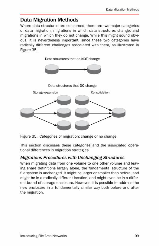
Data Migration Methods
Data Migration MethodsWhere data structures are concerned, there are two major categoriesof data migration: migrations in which data structures change, andmigrations in which they do not change. While this might sound obvi-ous, it is nevertheless important, since these two categories haveradically different challenges associated with them, as illustrated inFigure 35.
Figure 35. Categories of migration: change or no change
This section discusses these categories and the associated opera-tional differences in migration strategies.
Migrations Procedures with Unchanging StructuresWhen migrating data from one volume to one other volume and leav-ing share definitions largely alone, the fundamental structure of thefile system is unchanged. It might be larger or smaller than before, andmight be in a radically different location, and might even be in a differ-ent brand of storage enclosure. However, it is possible to address thenew enclosure in a fundamentally similar way both before and afterthe migration.
Introducing File Area Networks 99
Chapter 5: Brocade StorageX
The major difference between this scenario and any scenario in whichdata structures change is that a GNS is not, strictly speaking, requiredin this scenario. There are still benefits to having a GNS in place, butthe migration can be performed in a relatively seamless manner evenwithout a GNS.
To perform this kind of migration without a GNS, server names need tobe updated by either one of these methods:
• Decommissioning the source server, and using aliasing as amechanism for updating the physical path to the new destinationserver
• Decommissioning the source server, renaming the new serverwith the name of the retired server, and then removing it from thedomain and having Active Directory create a new security identi-fier for the server
This method—not using a global namespace—is not recommended,because it creates downtime for end users. Also, it is more than likelythat future migration tasks will not be as simple and therefore willrequire a GNS. Implementing the GNS up front on a simple migrationtask will make operations much easier when that day comes.
When a global namespace is used for a one-to-one migration, the pro-cess is transparent to the end user. The administrator performs thefollowing steps:
Create and configure a GNS if one is not in place.
Create a StorageX migration policy that copies shares from asource server to the destination. Configure the policy to updatethe GNS automatically.
Execute the policy. The policy will create new shares on the desti-nation server, copy the contents, and update the namespace.
Once you confirm that the destination server is operational and theenvironment is stable, you can decommission the source server.
100 Introducing File Area Networks

Data Migration Methods
Migrations Procedures with Changing StructuresChanging structures can mean going from one storage subsystem tomany, going from many to one, or radically changing the definitions ofshares even when you are going from one old subsystem to one newsubsystem. Figure 36 shows a migration with changing structuresbetween two arrays. The structural changes involve the way directoriesand shares are laid out.
Figure 36. Example of changing structure migration
For migrations in this category, a GNS should always be used, nd theprocess is transparent to end users
Create a GNS if one is not already in place.
Create a StorageX Migration Policy that copies share(s) from asource server to the destination server. Configure the policy torestructure the data in any way required. Also configure the policyto update the GNS automatically.
Execute the policy. The policy will create new shares on the desti-nation server, copy the contents, and update the namespace.
As before, once you confirm that the destination server is operationaland the environment is stable, you can decommission the sourceserver.
Introducing File Area Networks 101

Chapter 5: Brocade StorageX
Migrations Procedures with Server ConsolidationsServer consolidation is a special case of changing structure migration.Administrators will want UNC paths to remain unchanged when theunderlying files are moved to other servers or to other paths. Pathsmay be embedded in links, in applications, and in other places wherethe names are difficult to change. The Brocade StorageX consolida-tion roots function keeps UNC paths the same when moving theunderlying files within a path. StorageX performs an aliasing functionand responds to requests for a server name for which it is aliasing. Youcan use the procedure previously discussed, but in many cases, thefollowing procedure is preferable.
These are the steps to consolidate servers using this alternatemethod:
Disallow user access to the servers involved.
Create new DNS entries for retiring servers.
Rename the retiring servers to the name you specified in the newDNS entry. For example, rename Server01 to Server01-old.
Update the DNS entry for the original server names that each ofthe retiring servers were named, and point the DNS entry for thathost name to the server that now hosts the server consolidationroot.
Remove the computer from the Active Directory since it is now analias and no longer an existing computer.
If applicable, update the Windows Internet Name Service (WINS)database by removing any static entries that resolve the old servername.
Using StorageX, add the retiring servers to the Other Resourcesfolder in the Physical View.
Using StorageX, create a server consolidation root for each serverthat will be consolidated.
For each consolidation root, create links to the shares on the serv-ers that you want to migrate. For example, create links to sharesthat you want to migrate from Server01-old. When users nowaccess \\Server01\share, they will be redirected to \\Server01-old\share.
102 Introducing File Area Networks
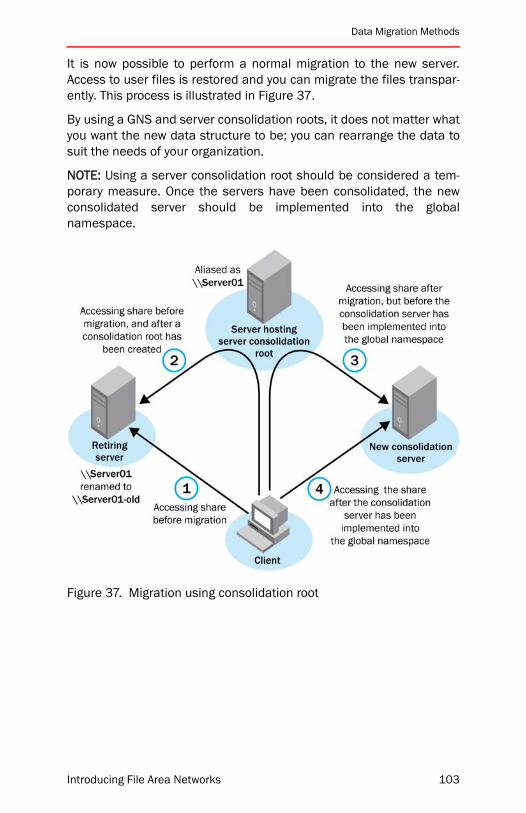
Data Migration Methods
It is now possible to perform a normal migration to the new server.Access to user files is restored and you can migrate the files transpar-ently. This process is illustrated in Figure 37.
By using a GNS and server consolidation roots, it does not matter whatyou want the new data structure to be; you can rearrange the data tosuit the needs of your organization.
NOTE: Using a server consolidation root should be considered a tem-porary measure. Once the servers have been consolidated, the newconsolidated server should be implemented into the globalnamespace.
Figure 37. Migration using consolidation root
Introducing File Area Networks 103
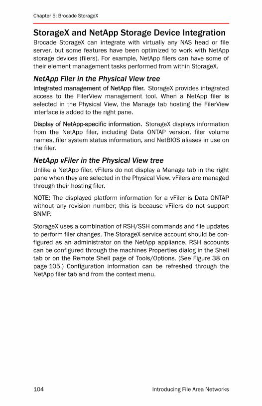
Chapter 5: Brocade StorageX
StorageX and NetApp Storage Device IntegrationBrocade StorageX can integrate with virtually any NAS head or fileserver, but some features have been optimized to work with NetAppstorage devices (filers). For example, NetApp filers can have some oftheir element management tasks performed from within StorageX.
NetApp Filer in the Physical View treeIntegrated management of NetApp filer. StorageX provides integratedaccess to the FilerView management tool. When a NetApp filer isselected in the Physical View, the Manage tab hosting the FilerViewinterface is added to the right pane.
Display of NetApp-specific information. StorageX displays informationfrom the NetApp filer, including Data ONTAP version, filer volumenames, filer system status information, and NetBIOS aliases in use onthe filer.
NetApp vFiler in the Physical View treeUnlike a NetApp filer, vFilers do not display a Manage tab in the rightpane when they are selected in the Physical View. vFilers are managedthrough their hosting filer.
NOTE: The displayed platform information for a vFiler is Data ONTAPwithout any revision number; this is because vFilers do not supportSNMP.
StorageX uses a combination of RSH/SSH commands and file updatesto perform filer changes. The StorageX service account should be con-figured as an administrator on the NetApp appliance. RSH accountscan be configured through the machines Properties dialog in the Shelltab or on the Remote Shell page of Tools/Options. (See Figure 38 onpage 105.) Configuration information can be refreshed through theNetApp filer tab and from the context menu.
104 Introducing File Area Networks
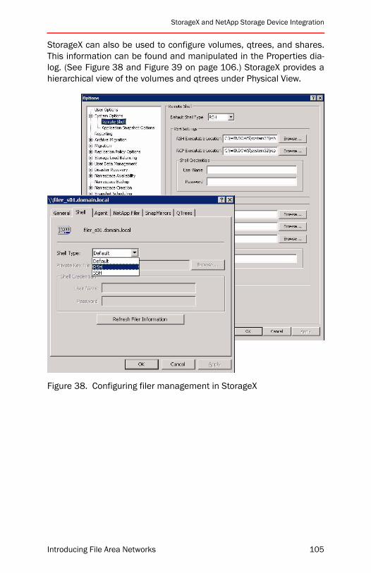
StorageX and NetApp Storage Device Integration
StorageX can also be used to configure volumes, qtrees, and shares.This information can be found and manipulated in the Properties dia-log. (See Figure 38 and Figure 39 on page 106.) StorageX provides ahierarchical view of the volumes and qtrees under Physical View.
Figure 38. Configuring filer management in StorageX
Introducing File Area Networks 105
Chapter 5: Brocade StorageX
Figure 39. Configuring volumes on a filer
106 Introducing File Area Networks
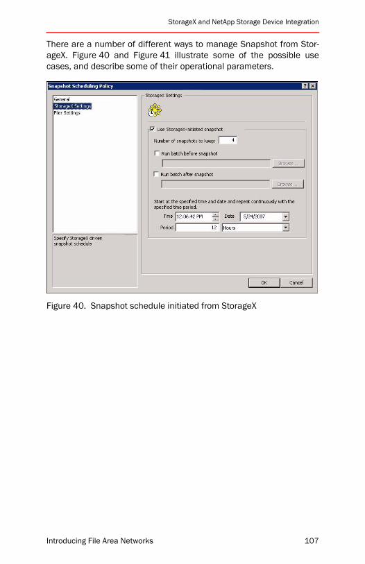
StorageX and NetApp Storage Device Integration
There are a number of different ways to manage Snapshot from Stor-ageX. Figure 40 and Figure 41 illustrate some of the possible usecases, and describe some of their operational parameters.
Figure 40. Snapshot schedule initiated from StorageX
Introducing File Area Networks 107
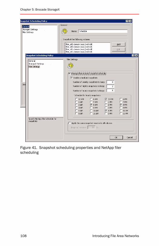
Chapter 5: Brocade StorageX
Figure 41. Snapshot scheduling properties and NetApp filer scheduling
108 Introducing File Area Networks

Troubleshooting
TroubleshootingThe most common problems fall into the following three categories:
• Installation
• GNS management
• Replication
This section provides guidance on resolving common issues in each ofthose areas.
Installation Problems• The account used to install StorageX from media must have
administrator privileges on the local system.
• The account used when running the StorageX console should bean administrator on the local system and have the appropriatepermissions to administer the DFS roots that are managed.
• The account used for the StorageX server, which is specified dur-ing installation, must have the following permissions andprivileges:
• Appropriate permissions to administer the DFS roots that aremanaged
• Administrator privileges on any machines hosting eithersource or destination data replications
• ”Run as service” privilege
In general, problems arise from lack of appropriate permissions to oneor more of the following:
• DFS root
• DFS root share
• Active Directory
• Root replica hosts
• Shares
• Directories
• Files
• Machines where StorageX components are installed
Introducing File Area Networks 109
Chapter 5: Brocade StorageX
Namespace Problems• Service account needs admin permissions on the server.
• Share permissions must give Full Control to the StorageX serviceaccount.
• Service account needs admin permissions on DFS objects.
• DNS forward and reverse lookup zones must be consistent. Incor-rectly configured DNS entries can cause many problems, such as:
• Incorrectly naming a server in Physical view
• Failure to create links
• Failure to create or manage roots
• Test the DNS forward and reverse entries by using the nslookupcommand.
• Refer to the domain-based root by its fully-qualified domain namewhen attempts to access it by its NetBIOS domain name areunsuccessful or result in inaccurate data.
Replication Problems• Check whether there are firewalls between the system hosting the
StorageX server or StorageX monitoring agent services and theintended destination system for the replication agents that areblocking the port where the StorageX Replication Agent service lis-tens (TCP port 6002).
• Check whether the console system or agent system is running apersonal firewall and whether the appropriate ports are open on itto allow communication.
• Check whether any process is already listening on the port theStorageX server and StorageX replication agent services use.
• Check that the system hosting the replication agent can ping thesystem hosting the StorageX server using the server name.
The following are tasks to complete when the replication agent fails todeploy:
• Check whether the system being deployed is up and reachable.
• Check whether there are network routing and infrastructureissues preventing network connectivity in both directions.
• If the target system is running Windows NT 4, check whetherMSXML3 is installed on the system.
110 Introducing File Area Networks

Chapter Summary
• Check whether the normal admin$ shares are published on thedestination system.
• Check whether the account under which the StorageX server ser-vice is running has privileges to write to the destination admin$share to install the replication agent.
• Check whether there are any firewalls between the system hostingthe StorageX server or StorageX monitoring agent services andthe intended destination system for the replication agents that areblocking the port where the StorageX server service listens (TCPports 6001, 6002 and 6005).
• Check whether any process (such as Exchange) is already listen-ing on the port the StorageX server and StorageX replication agentservices uses.
Chapter SummaryBrocade StorageX can facilitate 24×7 access to data through backupsand replicas across globally distributed locations. The StorageX GNScan be used to seamlessly expand networked storage by makingexpansion transparent to users. It increases administrator productivityby automating data management tasks such as migration, consolida-tion, failover, and remote site management. It can work alone ortogether with other Brocade products to simplify and accelerate DRmanagement in heterogeneous, distributed environments. The GNSfeature improves user productivity by simplifying access to distributeddata, and ensuring consistent views of networked storage across theenterprise. StorageX should form the core of any FAN solution, and itsfeatures will complement and enhance other deployed FAN products.
Introducing File Area Networks 111

Chapter 5: Brocade StorageX
112 Introducing File Area Networks

Introducing File Area Networks
6
Brocade WAFSBrocade Wide Area File Services (WAFS) technology provides reliableLAN-speed access to remote file servers over WANs, while consolidat-ing enterprise-wide storage for centralized management. “Chapter 3:Building Blocks” starting on page 31 discusses the product at a highlevel. This chapter covers the following topics:
• “WAFS Business Case” on page 114
• “Challenges to Centralization” on page 115
• “Brocade WAFS Architecture” on page 117
• “Availability and Integrity Benefits” on page 122
• “Other Architectural Benefits” on page 125
• “Edge Office IT Services” on page 125
• “Data Reduction” on page 133
• “Deploying WAFS” on page 137
• “Chapter Summary” on page 144
Instead of requiring a dedicated file server at every remote location,with the associated management overhead, users of Brocade WAFSare able to deploy all storage in a central location. This chapter pro-vides more concrete information about the product architecture andprovides real-world best practices on deployment and management.
Historically, WAN performance and reliability issues prevented a cen-tralized solution from being a realistic solution. If file data were movedfrom branch offices to central data centers, users at the remote siteswould no longer be able to work effectively because file access wouldbe too slow. WAFS centralizes primary storage while alleviating the per-formance penalties. A WAFS node replaces the remote file servers witha high-speed caching system: when users request files, the WAFS
113
Chapter 6: Brocade WAFS
product fetches the files using a WAN-optimized protocol, and main-tains a local cache of each file for high-speed save operations andsubsequent open operations.
Brocade WAFS eliminates the need for remote backup, overcomingbarriers of latency, bandwidth, and network reliability to solve adecades-old problem in distributed data management and applicationperformance. WAFS also addresses some of the world’s most problem-atic remote office IT issues, including storage and server proliferation,backup and restore management, business continuity, and Total Costof Ownership (TCO) optimization.
WAFS Business CaseWithout WAFS, organizations tend to create remote “islands” of data,with complicated and difficult replication and backup processes. Theoverall objective of WAFS is to enable server consolidation, and theobjective of consolidation is to move existing fragmented server envi-ronments toward a more secure, manageable, and adaptablearchitecture. In other words, move data from the islands to a single“continent,” which enables IT to respond rapidly and cost-effectively tocurrent and future business challenges and opportunities.
Scenarios where consolidation is relevant include:
• Regulatory compliance-driven projects
• Mergers and acquisitions
• Significant changes in structure or processes
An IT group may drive a consolidation project in response to decliningeffectiveness of its service in remote locations. For example, IT mightfeel that it is delivering unsatisfactory service levels or unreliable sys-tems in branch offices. Similarly, there might be long lead times tomake enhancements and perform maintenance at branch offices.Simplifying branch office infrastructure can resolve these issues.
Storage and server consolidation can provide business benefits in anumber of areas:
• Storage systems that are more cost effective, reliable, andscalable
• More consistent and appropriate IT support for corporate businessprocesses and goals
• Improved data accuracy, consistency, and accessibility across thebusiness
114 Introducing File Area Networks
Challenges to Centralization
• More effective use of IT skills and personnel.
• Improved IT service levels
• Increased value of IT systems
Challenges to CentralizationThere are four primary challenges to centralizing WAN-based file andapplication access. This section discusses those challenges and theirroot causes—and suggests how WAFS can meet these challenges.
WAN Latency and Protocol DesignSaving, opening, or transferring a file across the WAN can take min-utes. Sometimes, a disruption prevents the operation from successfulcompletion. The protocols involve thousands of individual round trips,all necessary and all very fast on a LAN. Because of WAN latency,access times on a WAN are two to four times longer than on a LAN.Protocols such as CIFS, NFS, and TCP were never designed to handlefile access in high-latency environments. Every round trip generated bythe CIFS or NFS protocol over the WAN incurs a high-latency delay, dra-matically impacting performance.
Lack of BandwidthLack of network bandwidth may be one cause of unacceptable speedfor users accessing files and applications remotely. Branch office WANbandwidth from T1, DSL, or frame relay connections can be 10 to 100times slower than LAN bandwidth. Competing for this limited band-width are a variety of applications—such as ERP, Voice over IP (VoIP),Web applications, and file transfers. Adding Virtual Private Network(VPN) and other network layers on top of the WAN can further reduceWAN bandwidth.
Lack of Data IntegrityWANs are inherently less reliable than LAN connections and may besubject to packet loss and network outages especially when con-structed using satellite or microwave link technology. Files in theprocess of being saved or opened can time out indefinitely, resulting indata loss. Recently changed files also run the risk of being lost inflight. User-derived workarounds further compromise data integritywith a proliferation of out-of-date or unprotected files.
Introducing File Area Networks 115

Chapter 6: Brocade WAFS
Residual Branch Office ServersCertain branch office services must remain at the branch office.Server and storage consolidation eliminates remote file servers,remote backup hardware (such as tape drives), and backup software.However, many other branch office IT services cannot be deliveredeffectively over a WAN and may force this type of server to remain atthe branches, undermining the consolidation project. For example, ITneeds to continue to provide branch offices services such as DHCP,DNS, domain controller, and print services, which cannot effectively beserved from the data center due to WAN latency. In addition, at eachbranch office, IT needs management software, server-related operat-ing system license/upgrade protection plans, and server-related anti-virus software services.
Summary: Workarounds Don’t WorkUnfortunately, the ideal consolidation and collaboration scenarios,which involve the need to share files in real time, do not take intoaccount the non-trivial technical challenges involved when remoteusers try to access applications or open, save, or transfer files over aWAN. The common issues of WAN latency and reliability, as well asinsufficient bandwidth, can translate into wait times of several min-utes when users attempt to open or save even a basic Microsoft Officefile. Users experience even longer wait times when they try to accesslarger files, such as those found in Computer-Aided Design (CAD),architecture, and product design environments.
If a Microsoft Word document takes three minutes to open and fiveminutes to save, and the relative lack of stability in the WAN environ-ment keeps corrupting or causing applications to crash, users willcomplain—and rightfully so.
And frustrated users usually come up with creative workarounds toavoid these issues. However, these workarounds—which often involvegargantuan e-mail attachments or copies of files stored in multiplelocations—cause even more problems. IT may look to invest in addi-tional WAN links in an attempt to solve the performance problem withadditional bandwidth, but all of these workarounds still do not addressthe root causes of application performance problems over the WAN.
116 Introducing File Area Networks
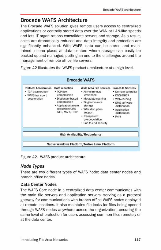
Brocade WAFS Architecture
Brocade WAFS ArchitectureThe Brocade WAFS solution gives remote users access to centralizedapplications or centrally stored data over the WAN at LAN-like speedsand lets IT organizations consolidate servers and storage. As a result,costs are dramatically reduced and data integrity and protection aresignificantly enhanced. With WAFS, data can be stored and main-tained in one place: at data centers where storage can easily bebacked up and managed, putting an end to the challenges around themanagement of remote office file servers.
Figure 42 illustrates the WAFS product architecture at a high level.
Figure 42. WAFS product architecture
Node TypesThere are two different types of WAFS node: data center nodes andbranch office nodes.
Data Center NodesThe WAFS Core node in a centralized data center communicates withthe main file servers and application servers, serving as a protocolgateway for communications with branch office WAFS nodes deployedat remote locations. It also maintains file locks for files being openedthrough WAFS nodes anywhere across the organization, ensuring thesame level of protection for users accessing common files remotely orat the data center.
Introducing File Area Networks 117
Chapter 6: Brocade WAFS
Branch Office NodesThe WAFS Edge node in the branch office accelerates access to datacenter servers for branch users through TCP optimization and intelli-gent caching of the active data set being used from various centralapplication and file servers. To branch office desktop computers, thenode looks just like a standard local server that also provides key ITservices such as domain controller, print, DNS/DHCP, Web caching,and software and application distribution (Microsoft SMS).
Core TechnologyTo accelerate file-sharing traffic, Brocade WAFS provides optimization,while maintaining the data integrity required to deliver secure, accu-rate, and cost-effective server/storage consolidation via a distributedfile system. By virtue of being file aware, the distributed file systemoptimizes CIFS/NFS protocols and supports end-to-end security mech-anisms such as SMB signing or IP Security (IPSec). It also maintainsfull availability and transparency for file read/write operations in caseof WAN disruptions and outages.
Unlike other WAFS products that force a tradeoff between perfor-mance and reliability, the Brocade WAFS distributed file systemtechnology incorporates a lock manager, journaling, and recovery. Thistechnology delivers maximum performance while protecting remoteusers from stale data, write collisions, WAN outages, and systemfailures.
This file-aware foundation extends CIFS and NFS shares over the WANtransparently, preserving all file-sharing semantics. Local data centerand branch office users actually use the same share/lock informationmaintained by the data center file server, exactly as if all users were inthe same physical building.
System-wide coherency and consistency are guaranteed, not onlyacross files accessed at any WAFS node, but across the entire enter-prise, including files accessed directly on the data center file server.This is possible because the nodes are aware of the location, nature,and status of all files. A distributed file system runs between the WAFSCore and Edge nodes, which uses the data center file server as theauthoritative arbiter of a file’s locked status.
118 Introducing File Area Networks

Brocade WAFS Architecture
Figure 43. Exemplary WAFS deployment
The following description of the flow of operations explains how thedistributed file system guarantees data integrity in unreliable WANenvironments. It represents the workflow that is triggered when a fileopen request is issued by a branch office user through the WAFS Edgenode.
WAFS Edge. If the file is cached locally, then a signature hash of thefile is sent along with the file open request through the WAFS Trans-port Protocol to the data center WAFS Core node.
WAFS Core. When a signature hash is received, the differencesbetween the file stored on the branch WAFS node and the version onthe data center file server are computed, and if there are differences,the entire file is prepared to be sent as a response. The response iscompressed and streamed to the branch WAFS node.
A CIFS lock request is made to the data center file server, and if suc-cessful, a lock is placed on the file on the file server. The file lockresult is notified in the response to the branch WAFS node.
WAFS Edge. The changes are applied to the file on the local cachestore, and the lock result is recorded. The file is ready to be read by thebranch office user, and is given read-only or read-write access depend-ing on the file lock result.
The distributed locking infrastructure highlighted above ensures thatfile updates made by one user will never conflict with updates made byanother. Updated files are always available to all users across the net-
Introducing File Area Networks 119

Chapter 6: Brocade WAFS
work. All file changes are synchronously logged to persistent storage atthe remote office, guaranteeing data integrity—even during WAN dis-ruptions, power outages, and reboots.
Performance Architecture and BenefitsFull Metadata CachingThe distributed file system implementation for Brocade WAFS ensuresthat a true on-disk hierarchy is maintained on the nodes for CIFS andNFS optimization. Full metadata consisting of file attributes, permis-sions, and security Access Control Lists (ACLs) are stored along withthe path names of the file objects. This metadata caching ensuresfaster directory/folder browsing experiences even for extensive hierar-chies where tens of thousands of file objects are stored at a singledirectory level.
The distributed file system ensures that metadata information for fileand directory objects are always kept up-to-date with the file servers atthe data center through synchronous metadata updates. A check ismade against the file server before performing an operation to create,delete, or rename files on the WAFS Edge node.
Full Asynchronous Write-BackWhen an application write request is initiated from desktops to serversthrough a WAFS node, the node has to ultimately send the write to thefile server via the data center/Core node.
Depending on the architecture of the WAFS system, there are two waysto handle write requests:
• Write-through—The node sends the write to the file server, waitsfor a response, and acknowledges the write to the application.
• Write-back—The node locally acknowledges the write and thensends the write in the background to the file server.
In the case of WAFS nodes, write-back is implemented by having thenode acknowledge writes to the application without first sending thewrite to the file server. Writes are streamed in the background to theserver. This technique hides latency from the application, leading tosubstantial improvements in performance, but introduces time win-dows where the application “believes” that the data is written to thefile server, but in reality the data has not been committed. Traditionalwrite-back inherently imposes a tradeoff between performance and apotential compromise on data consistency and safety. In order to makewrite-back implementations safe, significant enhancements, such as
120 Introducing File Area Networks

Brocade WAFS Architecture
sophisticated logging and recovery techniques, need to be in place toguarantee safe recovery in case of WAN disruption. This type of solu-tion is called “asynchronous write-back.”
Brocade WAFS overcomes traditional write-back issues by implement-ing full write-back through the use of logging and journalingtechniques, technology that allows recovery in case of network disrup-tions, crashes, or reboots of the host operating systems. File-awareWAFS systems manipulate and cache the entire file, inclusive of meta-data. They maintain the identity of a file rather than just the handle, soeven if the handle is lost, the file identity and location are maintainedby the file cache, and the file is always recoverable, as illustrated inFigure 44.
Figure 44. Write-back file locking architecture
Additionally, in Brocade WAFS, a file system-based implementationensures that the session context used to modify the file is always avail-able to transfer file updates to the file server at a later time.Furthermore, as long as there are pending writes on the branch officenode, the file remains locked on the data center, so that users cannotmake conflicting updates to the file. The system can always propagatethe modified file to the file server in the event of WAFS node reboots,WAN disruptions, or file server unavailability.
Introducing File Area Networks 121

Chapter 6: Brocade WAFS
Availability and Integrity BenefitsEnd-to-End SecurityTCP protocols often employ security at the application layer (layer 7) toensure complete end-to-end security between the client- and server-side components of an application. For example, the Server MessageBlock (SMB) protocol provides the basis for Microsoft file and printsharing and many other networking operations, such as remote Win-dows administration. To prevent man-in-the-middle (MTM) attacks,which modify SMB packets in transit, the SMB protocol supports thedigital signing of SMB packets. (In such attacks, a hijacker can poten-tially extract important user credentials by snooping packets out of aCIFS conversation. With this information, the hijacker would have theability to mimic a CIFS client to any CIFS server in the given domainwhere the users’ credentials are valid.) SMB signing ensures that theidentity of the file server matches the credentials expected by the cli-ent and vice versa. This policy setting determines whether SMB packetsigning must be negotiated before further communication with anSMB server is permitted.
NOTE: Windows Server 2003 comes with a number of default securitytemplates that are designed to help meet the needs of different com-puter security levels and functions. SMB Packet Signing is enabled bydefault on both the Highly-Secure (Hi-Sec) and Secure templates.
SMB signing has become a necessity with the release of a readilyavailable hacker tool called SmbRelay, which automates a man-in-the-middle attack against the SMB protocol. SMB signing protects againstSMB session hijacking by preventing active network taps from inter-jecting themselves into an already established session. Inline networkoptimization products rely on packet interception to implement theiroptimization and lose their ability to provide latency optimization whenSMB packet signing is enabled. As a result, these classes of productsforce organizations to make a choice between security andperformance.
122 Introducing File Area Networks

Availability and Integrity Benefits
Figure 45. WAFS security advantages
Brocade WAFS natively supports SMB packet signing. It is uniqueamong WAFS/WAN optimization products to fully support CIFS optimi-zation when SMB packet signing is enabled between the CIFS clientand servers. Enabling IPsec as a default security policy between CIFSclients and servers is yet another example that highlights the inabilityof the protocol snooping approach to operate in such environments,where Brocade WAFS natively supports such security policies.Figure 45 shows the difference between Brocade WAFS end-to-endsecurity versus competing approaches.
Full CIFS Disconnection SupportBrocade WAFS storage is tightly integrated with file-aware differencingand dictionary-based data reduction techniques in a single architec-ture. The locally held copy is kept up-to-date and treated efficientlyduring open and save operations. The distributed file system technol-ogy synchronizes the data center copy with the WAFS node in theremote office to make sure it is updated with the most recent changes,guaranteeing 100% consistency. The performance benefit to endusers, along with file coherency and consistency, ensures that userscan access files even during WAN disruptions. When the WAN connec-tion is restored, files are synchronized automatically.
Introducing File Area Networks 123
Chapter 6: Brocade WAFS
WAFS shields end users from WAN disruptions of up to several min-utes, allowing disconnection support under these conditions. Incertain environments, such as wireless/satellite or very remote loca-tions, longer-term periods of WAN disconnection can be regularevents. Additionally, even at remote offices in urban areas, WAN dis-connections can occur due to operator error, service providerscheduled maintenance, or physical disruption. The WAFS distributedfile system implementation allows branch users to work as seamlesslyas possible through periods of WAN disconnection without riskingcoherency and consistency of data.
This is a guarantee that no network-level acceleration solution canoffer. Only file-aware products can provide this benefit.
In disconnected mode, the branch office node enables the following:
• Allow browsing of cached directories/folders.
• Allow read/write access to any cached file.
• Provide the ability to continue working and save changes to a filethat was opened prior to the disruption. The changes to the fileare transparently updated to the data center file server uponresumption of connectivity.
• Allow creation of new objects (files and directories) through thebranch office node during the disconnected mode.
When WAN connectivity is restored, the new objects are created andany file updates are transparently applied to the data center file serv-ers. The feature provides corrective actions in case of conflictscenarios by retaining both versions of the document in conflict andnotifying the administrator via an SNMP trap or e-mail to take the cor-rective action.
It is important to note that all the above operations can be carried outtransparently on the same network drive that is used to access filesprior to the disconnection. Other solutions can require remapping ofnetwork drives to a local store on the branch office node in theirattempts to provide disconnection capabilities. This is unnecessary inBrocade WAFS.
124 Introducing File Area Networks

Other Architectural Benefits
Other Architectural BenefitsSingle Instance StorageBrocade WAFS Single Instance Storage technology ensures that filedata is only held locally at the edge—close to branch office users—withno data mirroring needed at headquarters. Freed from a requirementto double-size the data center, much larger numbers of branch officenodes can be deployed against a single node at the corporate datacenter.
Other WAFS solutions can require byte-for-byte matching mirrored atthe data center, leading to scalability limits and spiraling costs. Bro-cade WAFS provides the enterprise with flexibility in establishing itscache storage size, supporting RAID 1 and RAID 5 High Availability (HA)implementations. Although a WAFS node offers a storage size of250 GB cache, it actually provides access to all available data centerstorage—whether that is a 10-GB server at a singe data center or 100terabytes spread across several data centers.
The branch office node storage cache is self-managing and monitorspersistent RAID-based storage, intelligently providing real-time accessto the active set of data at the branch office.
Transparent Pre-PopulationWAFS can ensure that files are ready for users to work on when theyneed them by pushing out the file data (“pre-population”) to its peernodes at regular intervals, rather than waiting for the data to berequested by remote users. There is no need for external agents orapplications to perform this function. IT personnel can pre-positiondata at the edge—in advance of user requests—to distribute networktraffic more evenly throughout the workday and improve branch officeperformance.
Edge Office IT ServicesWith local IT services running on the WAFS Edge node, users at thebranch office will experience better response times to their print,authorization, and network service requests. Remote office hardwarecan be eliminated and IT management and administration can be sim-plified by consolidating multiple server functions onto a single device.File services, print services, domain control, and authentication areexamples of functions that can be handled by the Brocade WAFS node.
Introducing File Area Networks 125

Chapter 6: Brocade WAFS
Figure 46. Using WAFS to consolidate services in a branch office
Print ServicesPrint services provided by the WAFS Edge node handle printing locally,without requiring print requests to traverse the WAN. Branch office ITadministration and associated costs can be eliminated by the removalof dedicated branch office print servers.
Print service features on the Brocade WAFS node include:
• Native Windows Point and Print architecture
• Active Directory-enabled printer browsing
• Simplified print cluster installation and administration
• Web-based administration
Domain Controller ServicesUser logon processes, authentication, and directory searches for Win-dows domains are handled locally at the branch office with WAFSDomain Controller services. Using the native functionality available onWindows Server 2003, it has the following features:
• Local processing of authentication/login requests
• Support for these services during WAN outages
126 Introducing File Area Networks
Edge Office IT Services
Network ServicesWAFS network services take the headache out of administeringbranch office network access while improving end-user performance.A single WAFS Edge node can host DNS and DHCP server functions—ITadministrators can consolidate critical networking services into a sin-gle footprint. Some features include:
• DNS caching for branch office name resolution.
• Assignment of IP addresses via DHCP.
Web Caching ServicesFaster delivery of Web pages is achieved via HTTP object caching, thusproviding rapid and seamless branch office Web access and lowerbandwidth consumption. Built on Microsoft ISA (Internet Security andAcceleration) server technology, WAFS Web caching services meet theperformance, management, and scalability needs of high-volumeInternet traffic environments with centralized server management,including:
• Support for secure Web sites accessed via SSL
• Easily configured port numbers and cache size
• Scheduled cache pre-population
• Optimization for “split-tunnel” branch office environments withdirect Internet access
Management ServicesBrocade WAFS management services optimize software and applica-tion distribution at the branch office. Microsoft Systems ManagementServer (SMS) packages can benefit from WAFS with faster packagedownload and caching at the branch office. The benefits include:
• Central software distribution for remote office
• Faster download of software packages
• No repeat transmission of upgrade packages
• Seamless integration with WAFS deployments
Introducing File Area Networks 127
Chapter 6: Brocade WAFS
Protocol AccelerationWAFS Protocol Acceleration technologies are designed to overcomethe effects of latency on CIFS, NFS, FTP, HTTP, and other TCP-basedprotocols. These protocols were optimized for use across LANs. Theysend many acknowledgement requests and responses, and breakdata into chunks to transport them on the network. These acknowl-edgements—which are required to send or receive any data at all—arenegatively impacted by latency. The longer the distance, the higher thelatency—which results in increasingly degraded performance.
Application flows cannot ramp up to take advantage of the availablebandwidth, and the result is longer connection setup times andunderutilized links. Ironically, the more bandwidth is available, themore performance is wasted because only a small percentage can beutilized. Applications just sit idle waiting for tiny packets to makerepeated round trips across the WAN, instead of filling up the availablepipeline. Brocade WAFS delivers optimization for TCP and other proto-cols, which greatly reduce the impact of latency.
TCP AccelerationTCP is a reliable protocol used for transmission of data over IP net-works. However, there are TCP behaviors that work against higherlatency connections. TCP utilizes a sliding window mechanism to limitthe amount of data in flight at any time. When the window becomesfull, the sender stops transmitting until it receives new acknowledg-ments. Over long-distance networks where acknowledgments are slowto return, the TCP window size sets a hard limit on the maximumthroughput rate.
128 Introducing File Area Networks
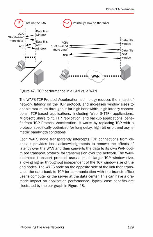
Protocol Acceleration
Figure 47. TCP performance in a LAN vs. a WAN
The WAFS TCP Protocol Acceleration technology reduces the impact ofnetwork latency on the TCP protocol, and increases window sizes toenable maximum throughput for high-bandwidth, high-latency connec-tions. TCP-based applications, including Web (HTTP) applications,Microsoft SharePoint, FTP, replication, and backup applications, bene-fit from TCP Protocol Acceleration. It works by replacing TCP with aprotocol specifically optimized for long delay, high bit error, and asym-metric bandwidth conditions.
Each WAFS node transparently intercepts TCP connections from cli-ents. It provides local acknowledgements to remove the effects oflatency over the WAN and then converts the data to its own WAN-opti-mized transport protocol for transmission over the network. The WAN-optimized transport protocol uses a much larger TCP window size,allowing higher throughput independent of the TCP window size of theend nodes. The WAFS node on the opposite side of the link then trans-lates the data back to TCP for communication with the branch officeuser’s computer or the server at the data center. This can have a dra-matic impact on application performance. Typical case benefits areillustrated by the bar graph in Figure 48.
Introducing File Area Networks 129

Chapter 6: Brocade WAFS
Figure 48. TCP protocol acceleration impact on applications
WAFS TCP Protocol Acceleration establishes a tunnel of optimized TCPconnections between WAFS nodes. As part of application request andresponses, connections are initiated by branch office clients to datacenter servers. A pre-established connection from the tunnel is usedfor each connection request, thereby eliminating time spent in the ini-tial handshake to set up TCP connections. The pool of connectionsalso gives the ability to transfer multiple data blocks simultaneously ina single time period, rather than use a single connection where trans-fers for data blocks are required to be queued up. This techniqueeffectively translates to a much larger window size between the clientand server, allowing higher throughput independent of the TCP windowsize of the end nodes.
The WAN optimized tunnel also employs transparent WAN retransmis-sion techniques for lost packets in connections, in which selectacknowledgements for lost packets are used to trigger retransmissionof TCP packets. This greatly improves default semantics of TCP whereall packets in a session are retransmitted, even when only a singlepacket is lost in transit.
130 Introducing File Area Networks
Protocol Acceleration
WAFS Transport Protocol AccelerationCIFS and NFS suffer from issues similar to other TCP protocols, butthey also present unique problems due to the fact that they employnumerous Remote Procedure Calls (RPCs) for file-sharing operations.Since CIFS and NFS were designed for reliable networks, frequent dis-connections or latency characteristics were not a designconsideration, thus they require special treatment when being usedacross a WAN. Some operations in CIFS and NFS are more susceptibleto interruptions than others, while some others require frequent retryoperations. Additionally, the NFS protocol involves a repetitive use of afile open/close RPC for every file read/write operation.
This design limitation of file-sharing protocols requires optimizationtechnologies that possess sophisticated application-level intelligence(operating at Layer 7 in the OSI network stack) to further mitigate WANround trips by applying specific heuristics based on a deep under-standing of CIFS/NFS protocols.
Instead of CIFS or NFS, Brocade WAFS nodes use a WAFS TransportProtocol to communicate with each other. While being totally transpar-ent to the CIFS or NFS servers at the data center, this WAN-optimizedfile-sharing protocol leverages several different technologies to accel-erate files and updates across WAN links.
To remove the transmission overhead of standard protocols, WAFSuses a technique known as “data streaming,” which dramaticallyimproves file access times and reduces network overhead. Standardfile-sharing protocols such as NFS and CIFS suffer from poor perfor-mance over the WAN because they wait for a uniqueacknowledgement for every 4 KB of data sent across the WAN. Thenext 4-KB block of data will not be sent across until the acknowledge-ment for the previous 4-KB block is received. Given the high round-triptimes in a WAN, the end-to-end can spend more time waiting foracknowledgments than it spends actually transmitting data.
Introducing File Area Networks 131

Chapter 6: Brocade WAFS
Figure 49. CIFS over a WAN without acceleration
In contrast, WAFS opens the file, compresses it, and then streams theentire file across the WAN without waiting for per-block requests.Acknowledgements for individual block requests are sent to the CIFSclient at LAN speeds, since all relevant file blocks are readily availableat the local WAFS edge node.
Figure 50. CIFS over a WAN with acceleration
132 Introducing File Area Networks

Data Reduction
Several additional technologies are layered into the WAFS TransportProtocol to further improve performance over the WAN. Read-aheadcaching ensures that in response to a particular file block request, thebranch office WAFS node starts fetching the entire file, anticipatingfuture file access patterns. This way, data is readily available in thecache data store, ahead of the read requests.
Data aggregation and I/O clustering techniques guarantee the effi-cient use of precious WAN bandwidth. Data aggregation ensures thatinformation regarding file updates made by several users at thebranch office is aggregated into a single message within the WAFSTransport Protocol. It conserves multiple round trips and packs datamore effectively. I/O clustering allows updates made to various partsof a file to be gathered over a short period of time and sent as a singleI/O update request with references to the individual changes.
With all the separate technologies incorporated in the WAFS TransportProtocol working in concert, typical users find 10 to 20X, even up to100X plus, improvements in performance across the WAN.
Figure 51. Impact of acceleration on file save time
The WAFS Transport Protocol in Brocade WAFS products is designed togracefully survive both short interruptions and longer network outageswhile insulating the end user and ensuring the security and integrity ofthe data. Sophisticated resiliency algorithms, which have been opti-mized for large file transmission, ensure the integrity of the data.
Data ReductionLeveraging aggressive compression and optimization technology thatis file-aware and application-intelligent, Brocade WAFS dramaticallyreduces the amount of data sent across the WAN. WAFS compressiontechnologies increase WAN capacity—with as much as 99 percentreduction in bandwidth—over the same physical links, improving appli-cation performance and user response times. WAFS optimizationintelligently utilizes data and file stores held locally at the branchoffice to cut back on redundant and unnecessary data transport, whilemaking the most of existing bandwidth.
Introducing File Area Networks 133
Chapter 6: Brocade WAFS
Data CompressionThe Brocade WAFS solution incorporates two compression techniquesto minimize the amount of physical data sent over the network. Thesetechniques significantly reduce the amount of data that must be trans-ported, saving both time and WAN bandwidth.
TCP Flow CompressionTCP flow compression reduces data at the flow level. Individual TCPpackets are compressed as they move across the network the firsttime. This stateless compression allows for data reduction on readilycompressible data streams, even on the first pass through the nodesusing well-proven algorithms similar to LZ data compression.
For example, if an HTML document is compressible by 70 percentusing applications such as WinZip, then bandwidth reduction benefitsof 70 percent will be immediately realized when the document istransferred for the first time through the WAFS nodes. Thereafter, forsubsequent transfers of the document, further level of data reductionbenefit is made possible from the dictionary-based compressiontechnology.
Dictionary-Based CompressionDictionary-based compression reduces data on the wire at the streamlevel for all TCP protocols. With this technology, new data streams arecatalogued and assigned a tag on both nodes at either end of a con-nection. When the sender attempts to transfer the same data streamagain, the much smaller tag is transferred on the WAN instead of theactual data stream. On the other end of the WAN link, the tag is usedto index the locally held data stream in the dictionary, and the originaldata stream is sent locally to the receiver. The result is elimination ofredundant data transfer over WAN links, achieving compression ratiosof up to 200 :1.
Among all modules in action for WAFS TCP optimization, the dictionary-based compression module works last in the optimization pipeline foroutbound packet flow (toward the WAN) and first for inbound packetflow (from the WAN). Since basic LZ-based compression is appliedprior to the WAFS dictionary-based compression, this technologybrings effective data reduction even for non-compressible data types,such as JPEG images.
134 Introducing File Area Networks
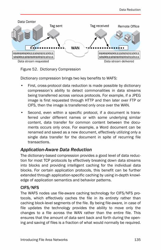
Data Reduction
Figure 52. Dictionary Compression
Dictionary compression brings two key benefits to WAFS:
• First, cross-protocol data reduction is made possible by dictionarycompression’s ability to detect commonalities in data streamsbeing transferred across various protocols. For example, if a JPEGimage is first requested through HTTP and then later over FTP orCIFS, then the image is transferred only once over the WAN.
• Second, even within a specific protocol, if a document is trans-ferred under different names or with some underlying similarcontent, data transfer for common content between the docu-ments occurs only once. For example, a Word document can berenamed and saved as a new document, effectively utilizing only asingle data transfer for the document in spite of recurring filetransactions.
Application-Aware Data ReductionThe dictionary-based compression provides a good level of data reduc-tion for most TCP protocols by effectively breaking down data streamsinto blocks and providing intelligent caching for the individual datablocks. For certain application protocols, this benefit can be furtherextended through application-specific caching by using in-depth knowl-edge of application semantics and behavior patterns.
CIFS/NFSThe WAFS nodes use file-aware caching technology for CIFS/NFS pro-tocols, which effectively caches the file in its entirety rather thancaching block-level segments of the file. By being file-aware, in case offile updates the technology provides the ability to move only thechanges to a file across the WAN rather than the entire file. Thisensures that the amount of data sent back and forth during the open-ing and saving of files is a fraction of what would normally be required.
Introducing File Area Networks 135
Chapter 6: Brocade WAFS
Proxy file locking employed by the WAFS nodes ensures that all filewrite and update operations can be safely sent asynchronously to thedata center.
The file writes are logged to disk on the branch office WAFS Edgenode, sending fast local acknowledgments to user applications so theydo not have to wait for this action to be completed over the WAN. File-aware optimization also dramatically improves file opening perfor-mance by serving locally held files out of the file-aware cache store.
Even in cases where the file may have been updated at the data cen-ter, the distributed file system ensures that the locally held copy is firstdifferenced and brought up-to-date against the data center copy. Thedifferencing and updating phase involves moving just the compressedchanges across the WAN—dramatically reducing the amount of datathat needs to be transferred.
MAPI/Microsoft ExchangeUp to 90 percent of Microsoft Exchange storage is in the form of largee-mail attachments. Without the Brocade WAFS solution, e-mailaccess to Microsoft Exchange Servers via the WAN is tediously slowand presents a major barrier to consolidation. Application-intelligentoptimization for Exchange natively integrates with Microsoft Exchangeand Outlook environments to speed the transmission of e-mail attach-ments over the WAN by holding and distributing e-mail attachmentsfrom remote nodes. This ensures that e-mail attachments are deliv-ered only once per branch office and that only file differences aretransmitted via the WAN when e-mail attachments are revised andsaved.
The WAFS Core node in the data center extracts attachments fromusers’ mailboxes and stores compressed, encrypted versions of theattachments on the cache data store. These attachments are thentransferred via the WAFS Transport Protocol to the branch office WAFSnodes in an efficient manner, resulting in data reduction benefits.When branch office users open e-mail attachments, the WAFSExchange Outlook option installed on clients redirects the requests tobe served locally from the branch WAFS node. The attachments areserved at LAN speeds to branch users, thus providing latency optimiza-tions. Bandwidth reduction benefits are observed through a single-instance transfer and use of the cache data store of the WAFS Edgenode for all recipients of the e-mail attachment.
136 Introducing File Area Networks

Deploying WAFS
HTTPWith WAFS application-intelligent caching of static Web pages, Webobjects are cached on the local WAFS Edge node at the branch officeand delivered through a Web proxy. The branch WAFS Edge node main-tains a cache of frequently used Internet objects that can be accessedby any browser client and that provide the content when subsequentusers request the same data. Objects accessed from the disk cacherequire significantly less processing than objects accessed from theInternet. Using cached content improves client browser performance,decreases user response time, and reduces bandwidth consumptionon the Internet connection. The cached data is available even whenthe Internet server is inaccessible because of a downed Internet con-nection, or even when the Web server itself is offline.
Deploying WAFSThe following sections discuss how the WAFS solution is deployedthroughout the organization.
At the Data CenterThe WAFS Core node is installed at the data center or main site to sup-port its community of branch office WAFS devices—without needingone-for-one mapping. Matching data capacity is not required since theunique single instance storage technology does not require mirroringof the distributed file system data.
At the Branch OfficeIn a distributed branch topology, in which storage is virtualized, thereare two options for user access:
CIFS: Mapped DrivesWindows PC users can map network drives directly using the explicitname of the onsite WAFS node. This method has the benefit of provid-ing a consolidated and virtual namespace to aggregate the pathnames from servers located at multiple data center locations.
Introducing File Area Networks 137
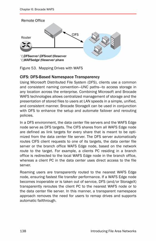
Chapter 6: Brocade WAFS
Figure 53. Mapping Drives with WAFS
CIFS: DFS-Based Namespace TransparencyUsing Microsoft Distributed File System (DFS), clients use a commonand consistent naming convention—UNC paths—to access storage inany location across the enterprise. Combining Microsoft and BrocadeWAFS technologies allows centralized management of storage and thepresentation of stored files to users at LAN speeds in a simple, unified,and consistent manner. Brocade StorageX can be used in conjunctionwith DFS to enhance the setup and automate failover and reroutingpolicies.
In a DFS environment, the data center file servers and the WAFS Edgenode serve as DFS targets. The CIFS shares from all WAFS Edge nodeare defined as link targets for every share that is meant to be opti-mized from the data center file server. The DFS server automaticallyroutes CIFS client requests to one of its targets, the data center fileserver or the branch office WAFS Edge node, based on the networkroute to the target. For example, a clients PC residing in a branchoffice is redirected to the local WAFS Edge node in the branch office,whereas a client PC in the data center uses direct access to the fileserver.
Roaming users are transparently routed to the nearest WAFS Edgenode, ensuring fastest file transfer performance. If a WAFS Edge nodebecomes inoperable or is taken out of service, DFS (and/or StorageX)transparently reroutes the client PC to the nearest WAFS node or tothe data center file server. In this manner, a transparent namespaceapproach removes the need for users to remap drives and supportsautomatic failthrough.
138 Introducing File Area Networks
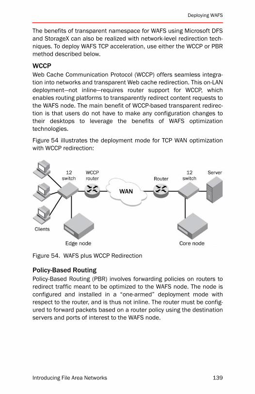
Deploying WAFS
The benefits of transparent namespace for WAFS using Microsoft DFSand StorageX can also be realized with network-level redirection tech-niques. To deploy WAFS TCP acceleration, use either the WCCP or PBRmethod described below.
WCCPWeb Cache Communication Protocol (WCCP) offers seamless integra-tion into networks and transparent Web cache redirection. This on-LANdeployment—not inline—requires router support for WCCP, whichenables routing platforms to transparently redirect content requests tothe WAFS node. The main benefit of WCCP-based transparent redirec-tion is that users do not have to make any configuration changes totheir desktops to leverage the benefits of WAFS optimizationtechnologies.
Figure 54 illustrates the deployment mode for TCP WAN optimizationwith WCCP redirection:
Figure 54. WAFS plus WCCP Redirection
Policy-Based RoutingPolicy-Based Routing (PBR) involves forwarding policies on routers toredirect traffic meant to be optimized to the WAFS node. The node isconfigured and installed in a “one-armed” deployment mode withrespect to the router, and is thus not inline. The router must be config-ured to forward packets based on a router policy using the destinationservers and ports of interest to the WAFS node.
Introducing File Area Networks 139
Chapter 6: Brocade WAFS
High Availability DeploymentsRedundant configurations at the data center and branch offices pro-vide business continuity and compliance by enabling High Availability(HA) features. WAFS provides HA in several ways:
Node RedundancyYou can configure two WAFS nodes as a redundant cluster, so onenode takes over in case the other node fails. The redundant node syn-chronizes its state and data with the active node in its idle time,staying up-to-date in the event it is called upon to take over.
WAFS failover technology keeps individual nodes highly available atthe data center and remote offices. Any critical node can be pairedwith another in an active/passive configuration. The system state andlocally held data are mirrored via a private network connectionbetween the units. When one device fails, the other comes online andtransparently takes over—and operations continue without manualintervention.
Site RedundancyAn organization can establish a DR data center at another location aspart of its business continuity strategy. WAFS supports topologies inwhich a redundant node can be deployed and configured at the sec-ondary data center, which is ready to take over when disaster strikes.
When the primary data center goes down, normal branch office opera-tions are restored by the activating Core node at the secondary datacenter and is transparent to all connected branch office nodes andbranch office users. This leverages any locally cached data in thebranch office nodes and preserves user performance and businesscontinuity.
Hardware RedundancyBusiness continuity is ensured with RAID, redundant power supplies,and cooling fans recommended for WAFS hardware configurationguidelines (and used in the WAFS appliance). In the event of a failure,these hardware redundancies ensure seamless operation until thereplacement parts are in place.
140 Introducing File Area Networks

Deploying WAFS
Flexible Platform OptionsPlatform Operating SystemsCompanies organize networks and choose operating systems (OSs)and file-sharing protocols to best solve the issues they face. Brocaderealized this from the beginning and designed the WAFS architecturefor platform independence. Trying to “shoehorn” a Linux-based appli-ance into a Windows-only company or forcing a Windows-basedappliance onto a Solaris and Linux group might cause managementheadaches.
The WAFS architecture uses a cross-platform code base that runs onboth Windows and Linux. This means that customers can choose theplatform that best fits into their network for seamless integration intotheir infrastructure without sacrificing functionality or performance.
Windows PlatformBrocade has taken the necessary steps to provide a scalable andenterprise-ready solution that is future-proofed against protocolchanges. As protocols such as CIFS and Messaging Application Pro-gramming Interface (MAPI) change over time, competitive networkoptimizer solutions will be forced to trail the introduction of new OSreleases by months or even years as they reverse-engineer the proto-col, if indeed they are able to do so. Since the Brocade WAFSarchitecture leverages native protocols and separates accelerationand optimization from specific versions of these protocols, WAFS willalways remain current as technologies change.
Of all current WAFS and WAN optimization vendors, only Brocade sup-ports all of the native Microsoft Windows features that today’sorganizations need to support their enterprise, as listed and describedbelow.
SMB Packet Signing. Brocade WAFS natively supports SMB PacketSigning, a technology which ensures that the identity of the file servermatches the credentials expected by the client and vice versa.
Kerberos Authentication. WAFS natively supports both Kerberos andNT Land Manager (NTLM) authentication modes. As Microsoft phasesout NTLM authentication with the Windows NT operating system, theWAFS product will continue to provide compatibility with Windowsinfrastructures.
Introducing File Area Networks 141
Chapter 6: Brocade WAFS
Active Directory Integration. To support enterprise best practices,WAFS Windows-based nodes can fully participate in an Active Directoryinfrastructure. In particular, the nodes appear in the domain and canbe managed as members of the domain.
Domain Controller Service. Unique among all of the WAFS and WANacceleration vendors, Brocade WAFS can support the installation ofthe Active Directory Domain Controller on its nodes. This allows userlogin processes, authentication, and directory searches for Windowsdomains to be handled locally at the branch office—effectively improv-ing end-user response times.
Active Directory Group Policies. Integration with Active Directory GroupPolicies enforces certain security or management policies for a groupof Automated Deployment Services (ADS) objects such as servers.WAFS Windows-based nodes honor group policies since they are a partof the Active Directory domain. For example, domain administratorscan restrict or disable local administrative or other user accounts with-out having to configure each node individually.
Linux PlatformThe WAFS solution is available for Linux-based servers to provide theWAFS and WAN optimization benefits for all TCP protocols. The Linux-based software can provide best-in-class optimization for the NFS pro-tocol through its unique distributed file-system-based proxyarchitecture. The Linux implementation has feature sets comparableto the Windows-based product, with the exception of the benefits spe-cific to the native Windows platform.
WAFS Linux-base software is a good fit for collaborative customer envi-ronments in the following industry verticals, in which NFS-based filesare prevalent:
• Software development
• Engineering /R&D
• Architectural Design
142 Introducing File Area Networks

Deploying WAFS
Platform HardwareMany enterprise customers have procurement and support agree-ments with IBM, HP, Dell, or other server hardware vendors. Thesecustomers may prefer to use their own server hardware and MicrosoftWindows Server 2003 R2 OS licenses and just purchase WAFS soft-ware-only solution from Brocade. By running WAFS software solutionson your preferred server-class platform, the solution can fit into yourexisting procurement processes, support agreements, and hardwareinfrastructure. Two software-only options are available. as described inthe following sections.
Software for Qualified Servers: Full InstallFull Install effectively replicates the exact partitioning and configura-tion of a Brocade WAFS appliance and supports all available features.Microsoft Windows Server 2003 R2 has to be provided by the cus-tomer and preinstalled on the server by Brocade ProfessionalServices. Currently this product is limited to the following qualifiedserver-class platforms:
• IBM xSeries 336
• IBM xSeries 346
• HP DL380 G3
• HP DL380 G4
• Dell PE 1850
• Dell PE 2850
Additional platforms are added periodically, and you should contactyour local Brocade sales representative for current information.
Software-Only Distribution: Branch Office SoftwareBranch Office Software can be installed on any machine that meetsthe minimum requirements for disk size, memory, and processor.Refer to the product documentation for up-to-date requirements. Thefollowing features are not supported in Branch Office Software:
• Brocade WAFS Exchange Services (WES) upgrade
• Failover (Core or Edge)
• Bandwidth throttling
NOTE: Full Install and Branch Office Software are available on CD orvia download from www.brocade.com.
Introducing File Area Networks 143
Chapter 6: Brocade WAFS
Chapter SummaryWith an average of 75 percent of corporate data now residing outsidea corporate data center, it makes sense that IT groups would want theoption of centrally managing, storing, and protecting important datathat exists at the periphery of their enterprise. Brocade WAFS providesIT departments with the tools to do just that, while maintaining enter-prise-class performance and availability levels at remote offices.
Companies are often disappointed when they do not reap the benefitsthey expected from data consolidation and when worker productivityplummets. On the other hand, IT managers who select solutions thataddress latency challenges can keep branch office users traveling “inthe fast lane,” while their companies enjoy the cost savings and con-trol consolidation projects can give them.
A point product may help solve parts of the branch-site application per-formance challenges. However, its limited functionality may mean thatthe IT organization still has to manage a range of other devices at theremote site, from print to Web proxy to DNS servers—all without a dedi-cated IT person in residence to manage day-to-day operations. What iscalled for is an integrated wide area performance solution. BrocadeWAFS is literally a “branch office in a box,” with secure, real-time dataaccess for remote users. With WAFS, organizations can boost the WANperformance of applications and file services, servicing thousands ofusers on a single server node. This approach enables companies tomeet their WAN optimization challenges with less redundant equip-ment and without requiring an upgrade to their WAN links.
144 Introducing File Area Networks
Introducing File Area Networks
7
Brocade MyViewBrocade MyView is discussed at a high level in “Chapter 3: BuildingBlocks” starting on page 31. This chapter provides more detailed infor-mation about deployment and management in the following sections:
• “System Requirements” on page 148
• “Namespace Design Considerations” on page 149
• “Namespace Implementation” on page 151
• “Chapter Summary” on page 152
Persistent news headlines about data theft, new federal regulations,and accounting irregularities demonstrate that these issues are preva-lent today in corporate America. Using MyView to create personalizednamespaces for users can help organizations combat data theft, com-ply with regulations, and audit internal activities. MyView softwareprovides a centralized view of user access and authorization to distrib-ute data throughout the enterprise.
MyView enables administrators to view enterprise-wide user accessand authorization from a single, unified console. It allows users toview and access resources for which the user has been granted per-missions throughout the enterprise via personalized namespace. Inaddition, it allows auditors to monitor which users have access towhich resources.
145

Chapter 7: Brocade MyView
The goal of MyView is to simplify access to resources throughnamespace virtualization, personalization, and organization.
Virtualization. Administrators can virtualize access to resourcesthrough the automated creation of a personalized namespace forevery user within the enterprise. A namespace enables users toaccess their files without having to know the physical location of thefiles. The MyView namespace permanently eliminates drive letterdependencies, providing administrators with flexibility in expanding,moving, and reconfiguring the underlying physical storage withoutaffecting users.
Personalization. An administrator creates a personalized namespacebased on the Active Directory domain authentication model, so thatusers have their own “personalized view” that displays only thoseresources they have authorization to access.
Organization. Personalized namespaces can be organized by catego-ries such as owner, department, location, and permission—enablingusers to view their resources in the way that makes the most sense totheir individual organization.
For systems administrators, MyView provides the following benefits:
• Simplifies user administration, thereby lowering the number ofsupport requests
• Increases data control by protecting and preserving enterprisesecurity rules and policies
• Increases infrastructure control through accurate documentationof the security model
For users, MyView provides the following benefits:
• Enables sharing of data
• Eliminates drive letter issues
• Simplifies access to data
• Provides customized views of resources
• Provides a single, logical view of the enterprise
Brocade MyView is not itself a complete standalone namespace prod-uct. Rather, it leverages the Microsoft Distributed Filesystem (DFS)Namespace (in Windows 2003). DFS is a storage service that can helpsolve many complex problems in the Windows environment. WhileMyView uses DFS, it also addresses some of its limitations.
146 Introducing File Area Networks
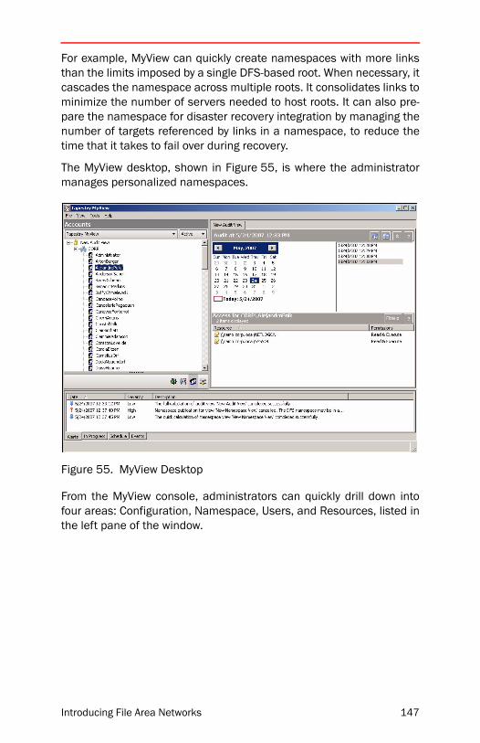
For example, MyView can quickly create namespaces with more linksthan the limits imposed by a single DFS-based root. When necessary, itcascades the namespace across multiple roots. It consolidates links tominimize the number of servers needed to host roots. It can also pre-pare the namespace for disaster recovery integration by managing thenumber of targets referenced by links in a namespace, to reduce thetime that it takes to fail over during recovery.
The MyView desktop, shown in Figure 55, is where the administratormanages personalized namespaces.
Figure 55. MyView Desktop
From the MyView console, administrators can quickly drill down intofour areas: Configuration, Namespace, Users, and Resources, listed inthe left pane of the window.
Introducing File Area Networks 147

Chapter 7: Brocade MyView
System RequirementsBefore you install Brocade MyView to build a Personalized Namespace(PN), make sure you review the following checklists of installationrequirements.
MyView Server and Client RequirementsThe following are server requirements for Brocade MyView:
• Windows XP or Windows 2003 or later
• Windows Script Host 5.6 or later
The following are client requirements for Brocade MyView:
• Windows 2000 SP3 or later
• Microsoft .Net Framework 1.1
• Internet Explorer 5.5 or later
MyView Database RequirementsThe following are database requirements for Brocade MyView:
• Microsoft SQL Server 2000 Desktop Engine (MSDE) SP3 or later
• Microsoft SQL Server 2000 Standard or Enterprise with SP3
• Microsoft Data Access Control (MDAC) 2.60 or later
MyView Disk Space RequirementsYou should have enough available disk space for any of the followingcomponents you want to install:
• Brocade MyView self-extracting file: 35 MB
• Client only: 55 MB
• Server only: 55 MB
• Client and Server: 60 MB
• Server and MSDE: 150 MB
• Client, Server, and MSDE: 150 MB
148 Introducing File Area Networks
Namespace Design Considerations
Namespace Design ConsiderationsTo achieve the benefits of namespace virtualization, consider layoutand design. Well-architected namespaces are designed around anorganizing principle such as geographical locations, functional areas,or hierarchical departments. This section discusses considerations fordesigning a namespace to ensure that it simplifies managementrather than adding a layer of unnecessary complexity.
Reduce ComplexityA single namespace can be designed with a great deal of complexity.For example, one namespace can provide many different paths to thesame data. However, you can also create multiple namespaces toserve the needs of different audiences. For example, you could use dif-ferent namespaces for Web content, software distribution, and so on.You may find that in the long run it is easier to manage multiplenamespaces than to create a single extremely complex namespace.
Consider ReliabilityConsider reliability requirements during the logical namespace designprocess. It is best practice to use domain-based roots as the entrypoint, because DFS replicates the configuration of the namespace(creates root targets) to allow it to be available from multiple servers.This eliminates the single server and prevents the namespace frombeing a single point of failure.
Cascaded NamespacesWindows Server 2003 supports creating links that point to other DFSnamespaces. This kind of link is often referred to as an “interlink” or“cascaded namespace.” Instead of specifying a shared folder as a linktarget, you can specify a DFS root or link within another namespace,allowing you to create a hierarchy of namespaces, or a cascaded DFS.Cascaded namespaces are often used to delegate administrationmore easily. If multiple groups within an organization want to managetheir own namespaces, they can do so and still present a single cas-caded DFS namespace to their users.
ScalabilityTo increase DFS scalability, organizations can combine the availabilitybenefits of domain-based DFS namespaces with the scalability ofstandalone DFS namespaces. For example, if you need to create10,000 links, but do not want to divide these between two domain-based DFS namespaces, you could take the following steps:
• Create a standalone DFS namespace with 10,000 links.
Introducing File Area Networks 149
Chapter 7: Brocade MyView
• Create a domain-based DFS root.
• Under the domain-based DFS root, create a link that points to thestandalone DFS namespace.
GuidelinesWhen linking to other namespaces, follow these guidelines to makecertain that clients can be redirected properly if a target is unavailable:
• If you plan to specify a domain-based DFS namespace as a linktarget (either the root or a link within that namespace), you cannotspecify alternate link targets. (Windows Server 2003 enforces thisrestriction.)
• If you plan to specify a standalone DFS namespace as a link target(either the root or a link within that namespace), you can specifyalternate link targets to other standalone DFS paths. Do not spec-ify domain-based DFS roots or shared folders as alternate targets.
IMPORTANT: The DFS tools do not prohibit you from specifying domain-based DFS roots or shared folders as alternate targets. Although youwill be allowed to do this, the resulting configuration will not functioncorrectly.
RestrictionsWhen linking to other namespaces, review the following restrictions:
• A DFS path can consist of no more than eight hops through otherDFS namespaces.
• Clients running Windows 98 might not correctly access links point-ing to other DFS namespaces. Windows 98-based clients can onlyaccess the following types of links to other namespaces:
• A link in a standalone DFS namespace that points to a stan-dalone DFS root or link.
• A link in a domain-based DFS namespace that points to astandalone DFS root. This technique works only if the clienthas the latest Active Directory client installed, as described inKnowledge Base article 323466, “Availability of the DirectoryServices Client Update for Windows 95 and Windows 98.”
150 Introducing File Area Networks

Namespace Implementation
DFS Namespace SizingSometimes it is necessary to estimate the size of each root and link inthe DFS Active Directory object. Each element in the namespace (rootname, link name, target path, and comments) takes up space in theDFS Active Directory object. The amount of space can vary dependingon the number of characters used in each element.
The following formula assumes that each element is 10 characters:
• Root: Approximately 300 bytes
• Each root target: Approximately 150 bytes.
• Each link in the root: Approximately 320 bytes.
• Each link target: Approximately 120 bytes.
For example, if you create a root (300 bytes) with three root targets(150 bytes × 3) and then add 100 links (100 × 320 bytes) with eachlink having three link targets (100 × 120 bytes × 3), the DFS ActiveDirectory object will be approximately 300 + (150 × 3) + (100 × 320) +(100 × 120 × 3) = 67 KB) in size.
Namespace ImplementationWhen creating a namespace, follow a rollout procedure similar to thefollowing:
• Identify the domains that contain users
Identify the Active Directory domains that contain users who willaccess their data through the namespace.
• Decide on the root configuration.
Decide whether to use a standalone or domain-based root as theentry point root to your namespace.
• Decide on the organization of the namespace
Identify the shares and folders that you want to associate with theusers and groups you specified previously.
Introducing File Area Networks 151

Chapter 7: Brocade MyView
• Calculate and publish the namespace
Calculate the namespace and review how the namespace willlook. Make any necessary changes and then publish thenamespace.
• Update login scripts or Active Directory
MyView provides example login scripts. To run these, check thatthe system is running Windows 2000 or later. In addition, the cli-ent machine running the login VBscript or Jscript must be runningWindows Scripting Host 5.6 or later.
Chapter SummaryBrocade MyView creates personalized namespaces for users to helporganizations combat data theft, comply with federal regulations, andaudit internal activities. MyView enables administrators to view enter-prise-wide user access and authorization from a single, unifiedconsole. It allows users to view and access resources and allowsauditors to monitor which users have access to which resources.MyView simplifies access to corporate resources through namespacevirtualization, personalization, and organization.
Well-architected namespaces are designed around an organizing prin-ciple such as geographical locations, functional areas, or hierarchicaldepartments You need to ensure that the design of the namespacesimplifies management rather than adding a layer of unnecessarycomplexity, while taking into account reliability and scalability. Whencreating a namespace, you need to identify the domains that containusers, decide on the root configuration, and then decide on the organi-zation of the namespace.
152 Introducing File Area Networks
Introducing File Area Networks
8
Brocade FLMBrocade File Lifecycle Manager (FLM) is discussed at a high level in“Chapter 3: Building Blocks” starting on page 31. This chapter pro-vides more detailed information about the product architecture andreal-world advice on deployment and management, in the followingsections:
• “Effect of Deploying FLM” on page 155
• “FLM In Action” on page 155
• “FLM Policies” on page 158
• “FLM and Backups” on page 159
• “FLM Deployment Tips and Tricks” on page 161
• “Chapter Summary” on page 182
According to Computer Technology Review, the world is currently see-ing “explosive growth” in enterprise data, especially unstructured filedata. Over the past few years, businesses have experienced unprece-dented growth in file data—as well as in the importance of that data—and this trend is not showing signs of slowing. As data volume grows, itbecomes more costly to store the data and more complicated to man-age it.
If corporations and governmental organizations were actively usingthis data, then it might be worth the expense of maintaining it on top-tier storage platforms, which ensures the highest level of performanceand availability. However, most often a very large percentage, say 80percent, of all stored files are not being used actively. In fact, mosthave not been accessed in the last 30 days, as illustrated in Figure 56.Storing this inactive data on primary storage devices is expensive, inef-ficient, and no longer necessary in Network Appliance (NetApp)environments thanks to FLM.
153

Chapter 8: Brocade FLM
Figure 56. Inactive vs. active data
According to the Storage Networking Industry Association, InformationLifecycle Management (ILM) is “the policies, processes, practices, ser-vices and tools used to align the business value of information with themost appropriate and cost-effective infrastructure from the time infor-mation is created through its final disposition.” FLM exemplifies acomprehensive, easy to use, file-optimized implementation of the ILMvision.
FLM is a data management solution that manages the lifecycle of filedata on NetApp filers, including the migration of inactive data to a vari-ety of secondary storage systems. It provides the following keyfunctions:
• FLM bridges the gap between primary and secondary storage.
• FLM uses automated policies to classify and manage file data.
• FLM remains transparent to users and non-disruptive toapplications.
• FLM simplifies compliance with information retention and mainte-nance regulations.
• FLM is highly scalable enabling administrators to manage multipleFLM servers from a single console.
154 Introducing File Area Networks
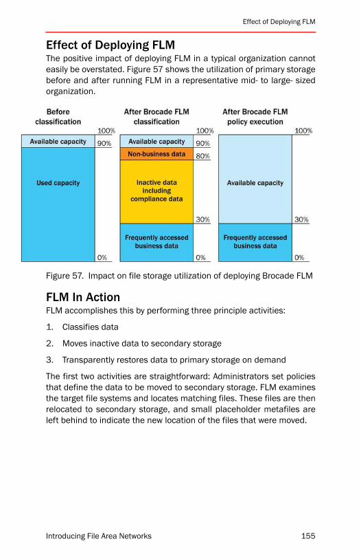
Effect of Deploying FLM
Effect of Deploying FLMThe positive impact of deploying FLM in a typical organization cannoteasily be overstated. Figure 57 shows the utilization of primary storagebefore and after running FLM in a representative mid- to large- sizedorganization.
Figure 57. Impact on file storage utilization of deploying Brocade FLM
FLM In ActionFLM accomplishes this by performing three principle activities:
1. Classifies data
2. Moves inactive data to secondary storage
3. Transparently restores data to primary storage on demand
The first two activities are straightforward: Administrators set policiesthat define the data to be moved to secondary storage. FLM examinesthe target file systems and locates matching files. These files are thenrelocated to secondary storage, and small placeholder metafiles areleft behind to indicate the new location of the files that were moved.
Introducing File Area Networks 155
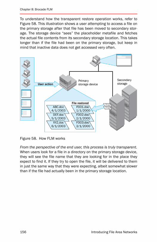
Chapter 8: Brocade FLM
To understand how the transparent restore operation works, refer toFigure 58. This illustration shows a user attempting to access a file onthe primary storage after that file has been moved to secondary stor-age. The storage device “sees” the placeholder metafile and fetchesthe actual file contents from its secondary storage location. This takeslonger than if the file had been on the primary storage, but keep inmind that inactive data does not get accessed very often.
Figure 58. How FLM works
From the perspective of the end user, this process is truly transparent.When users look for a file in a directory on the primary storage device,they will see the file name that they are looking for in the place theyexpect to find it. If they try to open the file, it will be delivered to themin just the same way that they were expecting, albeit somewhat slowerthan if the file had actually been in the primary storage location.
156 Introducing File Area Networks

FLM In Action
Figure 59 shows the way a user sees a directory:
• Before FLM migrated inactive files to secondary storage (top)
• After the migration (middle)
• After one file has been restored due to user request (bottom)
Figure 59. User view of relocated files
Introducing File Area Networks 157

Chapter 8: Brocade FLM
FLM PoliciesAt the heart of Brocade FLM is a powerful policy creation, manage-ment, and execution engine, which is used to simulate what willhappen before executing a “live” policy change, to migrate data fromprimary to secondary storage, and to configure the way in which FLMhandles restoration requests. Using FLM, you can configure automaticdeletion of files that have reached the end of their useful existence.Figure 60 shows the top-level architecture of the FLM policy engine.
There are a number of powerful administrator-configurable parame-ters in FLM policies, which optimize behaviors. For example, it ispossible to block excessive restores for scenarios in which this opera-tion could be useful, or even critical. In this scenario, a user executes afind operation that traverses a large portion of a storage device direc-tory structure and looks inside files for matching criteria. This actionwould potentially cause most or even all files to be restored from sec-ondary to primary storage. FLM can be configured to monitor this typeof behavior, and avoid making permanent restorations of large vol-umes of data in a short period of time.
Figure 60. FLM Policy Engine
158 Introducing File Area Networks
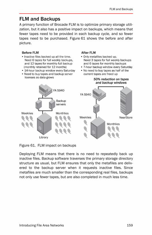
FLM and Backups
FLM and BackupsA primary function of Brocade FLM is to optimize primary storage utili-zation, but it also has a positive impact on backups, which means thatfewer tapes need to be provided in each backup cycle, and so fewertapes need to be purchased. Figure 61 shows the before and afterpicture.
Figure 61. FLM impact on backups
Deploying FLM means that there is no need to repeatedly back upinactive files. Backup software traverses the primary storage directorystructure as usual, but FLM ensures that only the metafiles are deliv-ered to the backup server when it requests inactive files. Sincemetafiles are much smaller than the corresponding real files, backupsnot only use fewer tapes, but are also completed in much less time.
Introducing File Area Networks 159
Chapter 8: Brocade FLM
To maintain high availability of data, organizations can still chose toback up the migrated data to tape. The frequency of backups formigrated data can be much lower than for active data and still guaran-tee full availability.
The following example explains the process.
1. An IT group performs full weekly backups of their active storageand keeps five full backup tapes.
2. On January 1, IT does a full backup before FLM does a migration.
3. On January 21, IT performs the migration using FLM, and File A ismigrated to the R200 secondary storage.
4. Subsequent full weekly backups of the active storage containMetafile A and not File A.
5. On January 29, the day IT rotates the oldest tape containing thefull backup, they must perform a full backup of the offline store onthe R200, where the migrated File A is located.
6. On February 5, the full backup overwrites the full backup from Jan-uary 1, leaving no copy of File A on tape.
7. On February 6, migrated File A becomes unavailable (perhaps itbecomes corrupt or is deleted from secondary storage, or the sec-ondary storage device goes down).
8. Here is the recovery process: a copy of migrated File A can beobtained from the January 29 tape, which contains the full backupof the secondary storage.
NOTE: If the entire secondary storage system goes down, File A can beobtained by retrieving the Metafile A and migrated File A from twotapes: the last full backup tape of the secondary storage, which con-tains migrated File A, and the oldest available full weekly backupassociated with the primary storage, which contains Metafile A’.
160 Introducing File Area Networks
FLM Deployment Tips and Tricks
FLM Deployment Tips and TricksWhen to Deploy FLMBrocade FLM is often considered for use in configurations in which astorage device is almost out of space on one or more volumes. If thefile system on the volumes is badly fragmented, as is often the casewhen the volume has been running at 99 percent capacity for a signif-icant period of time, this can place an undue performance burden onthe storage device. By introducing FLM before addressing the frag-mentation problems, storage device performance can be adverselyaffected. In this case, you should consult with Brocade and your Net-work Appliance representative about options to provide more space forproblem volumes and defragment them if needed.
In addition to disk utilization (in terms of both performance and capac-ity), CPU utilization should be measured prior to implementing FLM.Storage devices running between 80 and 100 percent CPU utilizationin single-processor systems may be significantly impacted by imple-menting FLM without the offline attribute support. Analyzemultiprocessor systems using tools such as “perfstat” or “statit” to geta more accurate picture of CPU utilization. Again, consult NetworkAppliance to ensure that CPU resources are adequate for multiproces-sor systems.
FLM is not a good fit for migrating data that users can select to makeavailable when offline. When users dock or undock their laptops, Win-dows will trigger restores of any files that FLM has migrated and usershave a copy of on their laptop.
Introducing File Area Networks 161
Chapter 8: Brocade FLM
General TipsBrocade FLM should be hosted on a minimum 2GHz dual-processorserver with 2 GB of memory. In addition, it is recommended the youuse Gigabit Ethernet links between the FLM server and the active stor-age, and between the FLM server and the secondary storage.
To avoid undesired changes to the secondary storage by applicationsor users, Brocade recommends the following configuration options:
• Make the secondary/offline share a hidden share. For environ-ments using DFS to reference secondary/offline locations, createa hidden DFS root and place links for the offline shares there.
• Set the security of the secondary/offline share to allow access byonly the FLM service account with Full Control. Alternatively, limitthe share to the local administrator group on the storage device/server where the offline share resides, provided that the FLM ser-vice account is a member of that group.
• If you are using CIFS auditing to increase scrutiny over changes tothe offline store, then set auditing on the secondary/offline storeand not primary store, as this will have a lesser impact on the envi-ronment. Note that if the secondary/offline store is on a filer, thenthe CIFS auditing has to be set from a Windows client via theAdvanced Security Properties tab for that folder.
• Consider using the offline pooling feature introduced in FLM 3.0.This feature enables files on the offline store to be distributedacross multiple qtrees or volumes within a single migration rule.This can be helpful if SLAs control the size of volumes or qtrees inyour environment as a means of limiting the time needed to backup or restore these items.
Brocade FLM uses an Microsoft SQL Server database to keep track ofconfiguration information and file locations. It is acceptable to eitherhave the SQL Server running on the same machine as the FLM serveror to have them on separate machines. However, management is sim-plified if SQL Server and FLM are located on the same machine. If FLMand SQL Server are installed on separate systems, consider the con-nectivity between the machines and coordinated management. Anychanges to the SQL Server installation must take into considerationthe potential effects on the FLM configuration (reboots, stop/start ofthe database, and so on).
162 Introducing File Area Networks

FLM Deployment Tips and Tricks
Performance and Scalability TipsTheoretically, one instance of FLM can serve any number of activestorage devices. In practice, however, for best performance it is recom-mended that one instance of FLM supports three active storagedevices (two maximum if there are more than 3,000 to 4,000 usersaccessing each of those storage devices). If the storage devices arenot heavily loaded, you can increase the number of storage devicesper FLM server. With FLM 3.0 and Data ONTAP 7.0.0.1+, you should beable to go beyond these numbers if you use the offline attribute. Theoffline attribute dramatically decreases the load placed on both thestorage device and the FLM server.
NOTE: You cannot use multiple FLM servers for a single active storagestorage device in a load-balancing configuration. A given active storemust have one, and only one, instance of FLM supporting it.
The FLM server is contacted only when a file is opened, created,renamed, or deleted on the active storage. Considering that the major-ity of the I/O activity on a storage device relates to read and write calls,FLM does not appear often in the data path. Also, when FLM receivesa file open, request, it does not contact its local database in order tocheck the file’s properties. When used with Data ONTAP 7.0.0.1 orgreater, FLM 3.0 offers the option of being notified only for clientaccess to files that have the offline attribute set. This significantly less-ens the traffic from the storage device to the FLM server and meansfile opens occur faster in the case of non-migrated files. The tradeoffof enabling this option, however, is disabling the FLM file blocking andthe automatic remigration features.
Another dimension to performance is the number of files that arebeing migrated or restored, since these events involve the FLM server.By tuning the migration criteria in FLM policies to accommodate fileaccess patterns you can minimize the number of files that are repeat-edly migrated and restored. Also, schedule migration to occur duringoff-peak hours so as to not cause network bottlenecks.
Another thing to consider when designing an FLM configuration is con-nectivity between the FLM server and storage devices. It isrecommended that a gigabit link be added to the storage device tosupport the migration and restore activities of FLM. A gigabit subnetcan be used for the FLM server, active store, and the secondary stor-age system hosting the offline store(s). If this is done, it isrecommended that the FLM server be multi-homed such that it isaccessible from the production network. This allows the FLM server tobe easily administered should the need arise and enables the use of
Introducing File Area Networks 163
Chapter 8: Brocade FLM
DFS for secondary store failover. A separate subnet may not beneeded if an extra gigabit port is trunked with the existing links to theproduction network. For capacity planning, FLM data transfers formigration or restore operations typically range from 10 to 40 MB/sec.
In regards to filer performance, NetApp Data ONTAP fPolicy can causea performance impact to the active store depending on the kind ofactivity on the filer. Typically, this performance impact is small. How-ever, fPolicy requests are sent to FLM 2.1 whenever a user orapplication opens, creates, or renames any file, regardless of whetherthe file has migrated unless the offline attribute is utilized. Therefore,when filers have very high CPU utilization and also have a large num-ber of file open, create, or rename operations, filer CPU impact shouldbe considered when you are designing the complete solution. Notethat neither the fPolicy nor FLM are inserted into the CIFS read andwrite operations that may be occurring on the filer; thus, these opera-tions are not impacted.
With FLM 3.0 and Data ONTAP 7.0.0.1+, the offline attribute canchange the above behavior. FLM 3.0 with Data ONTAP 7.0.1+ enablessupport for NFS. NFS read and write operations are intercepted if thefile was migrated to secondary storage. The NFS read and write opera-tions on non-migrated files are not affected.
File size also plays a role in performance. FLM generally providesgreater benefits when managing larger files. FLM adds an additionalstream to the source file, in addition to truncating it to one block forthe stub. The resulting file is two blocks plus an additional inode. OnNetApp filers, this represents approximately 8 KB. The recommendedminimum file size for migrations therefore is 12 KB.
You should analyze the mix of file sizes to ensure that an adequatenumber of files are above the minimum. If the file sizes are between8 KB and 12 KB, careful analysis should be performed to determinethe disk space savings.
Database growth can have an impact on FLM scalability. The impactwill be determined by factors such as record retention settings config-ured in the FLM GUI for “restore file details retention,” “deleted filedetails retention,” “statistics retention,” “events retention” as well as,the amount of migration, deletion, and restoration activity taking placein the FLM installation. Depending on the statistics and groomingparameters configured by the administrator, FLM can store records forthree to four million migrated files using the MSDE database, whichgrows linearly (for example, if there are 10 million migrated files, thedatabase will need to be 5 GB to 7 GB).
164 Introducing File Area Networks

FLM Deployment Tips and Tricks
FLM is not dependent on the database being available in order torestore migrated CIFS files to the active storage device. Once config-ured, FLM can restore files using the information from the active storeand the offline store, even if the SQL Server database is unavailable.In the case of NFS data, the database is required to be operational inorder to restore migrated files.
NOTE: In environments where performance is a concern, implementSQL Server on a separate machine.
Any time files are deleted or truncated on a primary storage, the oppor-tunity for fragmentation exists, as new files may be larger than thefreed contiguous blocks now available. If the new files are larger thanthese contiguous spaces, then that larger file will likely be placed inmultiple locations on the file system. Therefore, third-party utilitiesmay need to be run on the primary storage in order to defragment thefile system to increase performance.
Data ONTAP has commands such as “wafl scan” in pre-DOT 7.0 and“reallocate” in DOT 7.0+, which can assist in defragmenting a volume.However, consult a Network Appliance Engineer for guidance in usingthese commands.
In some environments, rules may aggressively move user applications(or files with the *.exe and *.dll extensions). The time required to ana-lyze and/or restore those files may impact the responsiveness of thatapplication. Since many users may be sharing access to these applica-tion binaries, excluding *.exe and *.dll files from FLM/fPolicy mayincrease performance.
If there is a gigabit link between the active store and the system host-ing the offline stores, it does not matter if the active store and thesecondary system are in separate locations. However, if there is con-siderable distance between the active store and the secondarystorage, then latency can cause significant performance degradation.Since the FLM server is contacted regularly by the primary storage, theFLM server should always be located near the primary storage. If thesecondary storage is in a remote location, it is important that the rulesbe tuned such that file restores occur infrequently to achieve optimumperformance.
Introducing File Area Networks 165

Chapter 8: Brocade FLM
Setting the Offline AttributeFLM 3.0 with Data ONTAP 7.0.0.1+ offers the option of only receivingfpolicy notifications from the filer in response to client access to fileswhose offline attribute is set. This means that opens of normal non-migrated files will proceed straight through without triggering an fpol-icy notification to the FLM server. Client access to non-migrated files isfaster and the load imposed on the filer by fpolicy is reduced. Thetradeoff is that file blocking and automatic remigration features aredisabled when offline notification is enabled.
NOTE: In mixed-protocol environments, in which FLM is handling bothCIFS and NFS data, use of the offline notification is required.
Setting the offline attribute on migrated files has additional benefits inthat this signifies to client applications that there may be a delaybefore the file can be opened. It also makes Windows Explorer lessaggressive in opening or searching these files.
Auto-Remigration and Auto-ExclusionThese features help in dealing with unintended restore operations andtuning migration criteria. Unintended restores may occur if users per-form full-text searches over directories containing migrated files.Rather than allowing files opened only during the process of a searchto linger on the active store, the auto-remigration feature allows thesefiles to be more rapidly sent back to the offline store rather than con-suming space on the active store until the next time the migrationpolicy runs. Since the data for such files typically still resides on theoffline store at the time that the automatic remigration runs, it simplyre-references the copy of the file already residing on the offline store,rather than having to copy the entire contents of the file back to theoffline store.
Auto-exclusion helps in automatically tuning migration rules. If FLMsees files that are frequently going back and forth between the activestore and the offline store because of the mix of migration and clientaccess operations, FLM automatically tunes the migration rule toexclude the problem files from future migrations. This allows these fre-quently used files to remain on the active store for faster client access.
166 Introducing File Area Networks

FLM Deployment Tips and Tricks
Security TipsWhere the active store and secondary storage systems are running indifferent domains, the account running the FLM service will need to betrusted and privileged in all the domains. In addition, the domainaccount used by the FLM service needs to be a member of the follow-ing groups and devices:
• The local admin group on the primary storage
• The secondary storage hosting the offline stores
• The machine that is hosting the FLM service
• The system hosting an external SQL Server database being usedfor FLM in installations where FLM is configured to use SQL Serverrather than MSDE
Permissions on the offline stores (shares) can be restricted so thatonly administrators have access. In addition, these shares can be hid-den to further protect them from unintended access. This does notaffect user-level access to the metafile on the primary storage, as longas the account used for the FLM server service still has full access tothe secondary storage. There is no need for the users to have accessto the secondary store.
The ACLs for metafiles can be changed by either running the commandfrom the system hosting the FLM server or using the FLM restoreblocking features to avoid recalling files when modifying their ACLs.
NOTE: Modifying ACLs requires opening a handle to the file, meaningthat changes to ACLs made from command-line tools or WindowsExplorer will cause FLM to restore files unless they are prevented byuse of FLM restore blocking capabilities.
Implementation and Management At this time, when a client requests a file that has been migrated, theclient must wait until the entire file has been restored. Where possible,customers should study their workflow so that large files are restoredin advance of need.
Occasionally, a storage device may run out of inodes when FLM isimplemented. When FLM migrates a file, it adds a named alternatedata stream to the file, which contains the metadata required torestore the file. The extra alternate data stream consumes an extrainode in the primary storage file system. When the primary storageruns out of inodes for a file system, it returns a “disk full” message to
Introducing File Area Networks 167

Chapter 8: Brocade FLM
applications that attempt to add a file (or alternate data stream) to thefile system. Disk-full conditions can also be reported in cases whereData ONTAP quotas are restricting the account running the FLM server.
On NetApp filers, the number of inodes available on a file system canbe increased by changing the maxfiles value for the volume/file sys-tem. Refer to the NetApp filer product documentation or contact aNetwork Appliance representative for details.
In general, it is recommended that the database be backed up on adaily basis. It is possible to back up the FLM configuration without sus-pending FLM operations. The flmbackup and flmrestore utilitiesaccept command-line arguments specifying the location where thedatabase resides.
This functionality is described in documents available for downloadfrom www.brocade.com.
Whether or not FLM Manager can be run on a scheduled basisdepends on the administrator’s concern about orphaned files in thesecondary storage. It also depends on how users delete metafiles. Forexample, if a user selects a file in Windows Explorer and then pressesthe Delete key (or selects Delete from the File menu), Explorer opensthe file as soon as the user selects it. This means that the file isrestored to the active store before it is deleted; therefore, there are noorphan files left on the offline store. If a user selects and deletes adirectory, then the metafiles in the directory are not restored beforethey are deleted. This can lead to orphan files on the offline store.
It is recommended that you run the FLM Manager periodically (typi-cally monthly) using the option to check against the database. The runtime will increase with the number of migrated files, so it may be desir-able to initiate the scan at the beginning of the off-peak period. Filesthat are missing their metafile are detected and listed as errors. Thesefiles can be displayed by selecting Missing Active Files in the Show fil-ter. The list can be further narrowed by entering a directory name inthe name filter and clicking the Find button. Once the collection of filesis narrowed down to those that should be cleaned from the secondarystorage, select the remaining files and click Delete. The administratorcan also choose to repair the metafiles by clicking Repair or restorethe files by clicking Restore.
Depending on how actively the FLM server is migrating and restoringfiles in combination with the amount of data under management, it isrecommended that the indices on the SQL Server database be defrag-mented if FLM performance starts to suffer.
168 Introducing File Area Networks

FLM Deployment Tips and Tricks
During the first (major) migration, there is a recommended workflow:
1. Scan shares with initial estimates for the rule settings. Keep a tar-get amount of free space in mind.
2. Tune the policy such that the amount of file data selected by thescan closely equals the amount of free space desired.
3. Some settings to consider:
a. At the Active storage level, consider and enter values for:
File Retention—Refer to the discussion of grooming onpage 164 and the interaction between the life span of mini-files in snapshots or tape backups and data in the offlinestore.
Restores Per Minute—In general, restore throttling should beavoided unless you specifically need it for your site. Leave thisoption turned off unless the restore activities impact the net-work or storage device load. If this happens, then the policymay need to be examined for rules that migrate files that areaccessed frequently. Restore throttling can be helpful to miti-gate the impact of a user running full text searches acrossmigrated files and thereby triggering mass file restore opera-tions. Administrators need to decide whether they want todeny users this type of search access to their migrated files byusing restore throttling.
File Blocking—Based on the judgement of administrators, forexample, marketing user folders are allowed to contain MP3files, but all other shares are not (assuming that marketinghas a legitimate business reason for having MP3 files, whileothers do not).
Blocked Restores—Set to the IP address or user account ofmachines running scheduled full virus scans or CIFS-basedbackups, file indexing, reporting, or other applications whichopen large numbers of the files on the active store via CIFS.
If there are files that will never be migrated, such as fre-quently used executables stored on the storage device, youmay want to exclude files with these extensions from scanningvia the Data ONTAP fpolicy command at the storage devicecommand prompt. This can speed client access to these fileswhen they are needed. It is important that when inclusions orexclusions are configured on the fpolicy command line, thatFLM migration rules are configured so that files eliminated
Introducing File Area Networks 169
Chapter 8: Brocade FLM
from fpolicy scans are never migrated. If such files aremigrated, they will not be restored in response to clientaccess operations.
b. At the policy level, consider and enter values for:
Exclude directories—There are two key scenarios in whichdirectories would be excluded from a scan (for migration):
• When the directory contains backup files, administratorfiles, system files, and other files essential to the opera-tion of the storage device.
• Directories that contain data pertaining to live projects. Itis recommended that any temp and system directories beexcluded.
NOTE: FLM automatically excludes snapshot (~) directoriesfrom migrations.
Migration bandwidth—It is recommended that you leave thisblank unless the migration is taking too much bandwidth orthe administrator needs to run the migration during businesshours.
Schedule—It is recommended that you leave this at thedefault value of zeroes initially as the initial migration (usuallythe most significant) is a planned data movement exercise.After the initial migration, the schedule can be set to runweekly or monthly during off-peak hours (when users or appli-cations are not accessing the file system).
c. Scan Only—It is recommended that you leave this setting atNo so migrations can be performed. This policy can be set toYes when the administrator does not want to effect any realdata movement (migration or deletion) such as when running“what if” scenarios to evaluate the potential effects of amigration.
d. At the rule level, consider and enter values for:
Migration Text—This message text is shown to the user whenthe user accesses a metafile and the file contents cannot berestored. It is recommended that you leave this blank if pro-longed outages of the offline store are not expected. Thissetting can be used to create custom scripts that tell if a filehas been migrated or not based on the text in the metafile.
170 Introducing File Area Networks
FLM Deployment Tips and Tricks
Action—If delete is used, it is best to also select the option to“Copy to offline storage before deleting” as a wastebasketapproach to deletion. This covers any mistakes in configuringthe policy. See the discussion of grooming on page 164.
Disabled—It is possible to disable individual rules within a pol-icy. When disabling individual rules, it is important tounderstand that other rules in the policy will run despite a sin-gle rule being disabled. Consider a policy whose first rulemigrates foo*.doc and bar*.doc to offline store A and whosesecond rule migrates *.doc files to offline store B. When bothrules are enabled, *.doc files are migrated to separate offlinestores based on whether they match foo* or bar* or *.doc. Ifthe first rule is disabled and the policy is run, all the *.docfiles will match the second rule and be migrated to offlinestore B.
Scope—Most rules should be scoped. The rule will affectshares that are entered. See also the discussion below onrule setup.
High Watermark—It is recommended that you leave this at thedefault value of 0 percent (off) unless a certain percentage ofusage for the volume hosting the share should be used as atrigger for performing migrations.
Include files—Use to specify migrations based on certain typesof files.
Exclude files—Excludes database files and certain executa-bles (for example, *.exe, *.bat, *.js, *.com).
File Age Criteria—Use the Brocade FileAges utility to obtain anunderstanding of the relative age of files on a given share, toformulate the initial estimates.
• Creation Date (CIFS only)—The date the file was created.This is the least useful indicator for administrators toassess the suitability of a file for migration. Separately, anirregularity could potentially occur such that the creationdate could look as if it were later than the modified date.This would most likely be a result of the file having beenrestored from another system. In that case, the file sys-tem creates the file with a new timestamp, but keeps thetimestamp for the modification date from the previoussystem.
Introducing File Area Networks 171

Chapter 8: Brocade FLM
• Access Date—The date the file was last opened by a userto read its contents. This date is also updated when cer-tain applications and processes, such as backup orreporting, access the file. If you use this value in settingmigration criteria, 180 days is the recommended cutoff.
• Modified Date—The date the file was last written to.Whereas the access date can be misleading (for example:all files could show as being accessed in the last 30 days,because an application has scanned the entire file sys-tem), the modified date can be used as one of the keyparameters for migrating data to secondary storage. Ifyou are using this date, 180 days is the recommendedcutoff.
File Size Criteria—For performance reasons, experiment withthe minimum and maximum file size settings with an eyetoward migrating the maximum amount of data with the leastamount of files. In order to avoid long restore windows andpotential network bottlenecks, some large files should be kepton the active store rather than being migrated to the offlinestore. When determining file size criteria, consider that NFSmetafiles are 4094 bytes, that CIFS metafiles consume twoinodes (for main and alternate data streams) plus 4 KB if nomigration text is configured or 8 KB if migration text isconfigured.
File Attribute Criteria—It is recommended that you set the Hid-den and System options to Not Set such that no hidden orsystem files are migrated.
Keep at least 15 percent of free space on the active store to accom-modate restore operations of migrated files. In addition, NetworkAppliance may recommend a certain amount of free space for perfor-mance reasons. Contact your Network Appliance representative foradditional information.
To prevent thrashing, start with one week as a check to see how manyrestore actions are generated within a week of files being migrated (abar chart is also available for analysis of restores). If the policy is age-based, then too many restores may mean that you will want to adjustthe file age criteria, for example, increase from 120 days to 180 daysor vice versa.
172 Introducing File Area Networks
FLM Deployment Tips and Tricks
Rules should be ordered from specific to general so that the specificrule has the first opportunity to act on files before the general rule isinvoked to process the remaining files. For example, a rule to migrate*mkt*.doc files should be earlier in the order than a rule to migrate*.doc files in the same policy. If files matching *.doc are migrated first,no files will remain for the *mkt*.doc pattern to match.
The same logic applies to migrating files older than one year tooffline A and files older than two years to offline B. The administratorneeds to put the files older than two years onto offline B before run-ning the sweep for files older than one year. If you do not migrate thefiles in this order, everything older than one year will be migrated tooffline A.
A subdirectory copy always restores all migrated files in the subdirec-tory tree. This is the desired behavior, otherwise there would be twometafiles pointing to the same offline file. When one of those meta-files is restored and the offline file is groomed, the other metafilewould be orphaned.
A subdirectory move may or may not restore migrated files in the sub-directory tree. If the move is within the same share, metafiles can bemoved as desired. For example, renaming the subdirectory from acommand prompt (or Windows Explorer) renames the subdirectorywithout attempting to copy the files, thus leaving the metafiles inplace. Similarly, using the rename command to move the subdirectoryfrom a command prompt (or using Windows Explorer to drag and dropthe subdirectory) within the same share preserves migrated files.
However, if one or more files and/or subdirectories within the directorytree are in use, the move operation copies as many files as possible,then prompts with a “cannot delete source” message. This thenresults in migrated files being restored, since a copy was really per-formed, even though the user intended to perform a move. The easiestway to move directories within a share without restoring migrated files,is to do so from the server where FLM is installed or use the restoreblocking feature.
There are two ways to locate a specific file among migrated, restored,or deleted files. In either case, the administrator can use wildcardcharacters (*) as part of the search:
• Use the search parameter in the various views in the FLM GUI.
• Use the Migrated File Tool in the FLM Manager, in which the viewcan be filtered to display only migrated files prior to the search.
Introducing File Area Networks 173

Chapter 8: Brocade FLM
If the FLM database logs fill up, you have options:
• Turn-off the logging of transactions in SQL Server.
In the case of disaster recovery in response to database corrup-tion, FLM can restore migrated files using the information in thefiles on the online and offline storage as long as the offline loca-tion has not changed since the files were migrated. So, you canturn off the transaction log. Brocade advises you to take frequentFLM configuration backups in this case.
• Use frequent transaction log backups.
You can schedule a weekly or biweekly database backup and dailytransaction log backup. This will free up the space for the transac-tion logs and if you lose the database for some reason, you canrecover the data by restoring the last database backup and thenrestoring every log backup since the database backup.
• Use checkpoints.
Checkpoints flush “dirty” data and log pages from the buffercache of the current database, minimizing the number of modifi-cations that have to be rolled forward during a recovery.Checkpoints save time in a subsequent recovery by creating apoint at which all modifications to data and log pages are guaran-teed to have been written to disk.
• Defragment the database.
This does not require stopping the FLM service, but take intoaccount that this process is typically slow. It has been known totake more than a day to defragment some databases.
• Re-index the database.
This requires the FLM service to be stopped, but is faster thandefragmenting.
It is generally acceptable to switch to the “simple recovery model,”because a “point in time” restoration of the database is not needed. Ifthe database is lost, FLM can still restore the migrated files as long asthe offline store has not been changed since the files were migrated.To restore previously configured policies and rules, FLM configurationbackups need to be taken. In the event of database loss, the only thingthat will not be restored is the list of recently migrated and restoredfiles, since this information is stored in the database.
174 Introducing File Area Networks
FLM Deployment Tips and Tricks
Data Availability and Recovery FLM can be used to support DR site configurations. In this case, theDR site should have a similar configuration to the production site. Forexample, both sites might have one storage device and one NearStoredevice. If the production site goes down, there are steps to follow touse FLM in the DR site. The following procedure assumes that the DRsite is a DR-only site and will be used only while the production site isbeing brought back online. The DR site is not intended for normal day-to-day operations.
To prepare:
1. Install FLM on a standby system at the DR site.
2. Export only the FLM configuration information, not the completedatabase, from the FLM machine at the production site to a loca-tion accessible from the standby FLM system at the DR site.
3. Start the FLM machine at the DR site and keep the serviceoperational.
If the production site goes down:
1. Import the FLM information from the location where it was savedto the standby FLM machine at the DR site. In environments per-forming NFS migrations, the entire database must be restored atthe DR site. If only CIFS file data has been migrated, the restoreoperation at the DR site need only restore the FLM configurationinformation.
2. Change the name of the active store and offline store to reflectthe names of the storage device and NearStore at the DR site.
NOTE: This step is not needed if you are using vFiler DR (NetAppMultiStore) to fail over from NetApp filers at the production site tothe filers at the DR site.
3. Enable the database lookup feature in FLM by adding a value tothe registry on the machine hosting FLM at the DR site:
a. Run regedit.exe.
b. Navigate to: HKLM\Software\NuView\FLM\Server key
c. Add a DWORD value to this key by right-clicking and selectingthe New-> DWORD value menu item. The value name is FPRe-questLookupOffline and the value must be set to 0x1.
Introducing File Area Networks 175
Chapter 8: Brocade FLM
When the DR site becomes operational, the key objective of theadministrator is to ensure access to migrated data from the offlinestore (at the DR site), as compared with running the file managementpolicies. Therefore, the standby FLM system at the DR site does notrequire the complete FLM database. Only the configuration informa-tion is required so that the database lookup function in FLM returnsthe correct location of the migrated file during the restore process. TheFLM backup script allows administrators to back up and restore onlythe configuration information. Since the configuration information con-sumes very little space in the database, this removes the need for aSQL Server instance at the DR site and allows use of the MSDEinstance that comes standard with FLM.
NOTE: In this configuration, the database at the DR site will not keep arecord of restore actions, since it does not have the detailed recordsportion of the database.
At this point, for CIFS data, only the configuration portion of the data-base has been used at the DR site. When the production site is backup (and the production storage device/NearStore have been synchro-nized with those at the DR site), some orphaned records will bepresent in the FLM database. This is because some migrated files mayhave been restored to the active store at the DR site, which will appearas migrated files in the database of the FLM system at the productionsite. These records can be easily cleaned up by using the Migrated FileTool in the FLM Manager.
If the full database has been used at the DR site (as is needed for NFSdata), the only requirement at the production site is to re-import (to theFLM system at the production site) the detailed records portion of thedatabase. Do not re-import the configuration portion of the database.The configuration portion for the FLM system at the DR site includesdetails for the storage device/NearStore at the DR site, which have dif-ferent names from the storage device/NearStore at the productionsite.
The unavailability of the FLM server has no impact on access to filesthat have not been migrated off the active store. If a standalone FLMserver goes down, migrated files will not be restored to the active stor-age device. Users who attempt to open a metafile will see the pre-configured message in the metafile (set by the FLM administrator dur-ing the FLM setup). Access to non-migrated files continues withoutinterruption in the absence of the FLM server.
176 Introducing File Area Networks
FLM Deployment Tips and Tricks
FLM can be installed on a Microsoft Cluster Server (MSCS) cluster forhigh-availability. The key factor in deciding whether clustering isrequired is the duration of time for which an IT department is willing toaccept denial of access to migrated files. If denial of access tomigrated files is not an option, then it is recommended that you clusterthe FLM server. If a certain amount of downtime for migrated files istolerable, the solution would fall under one of the following scenarios:
Configuration 1. The FLM server and its SQL Server database areinstalled on separate machines. An additional Windows machine isavailable to host FLM if the primary FLM system fails.
To prepare for potential failure of the FLM server:
1. Install FLM on a standby system.
2. Configure FLM on the standby system so that it will connect to theSQL Server database when FLM is started.
3. Stop the FLM service on the standby system and set the FLM ser-vice to either disabled or manual startup in the Windows ServiceControl Manager. This ensures that the FLM service will not startinadvertently if the host system is rebooted. Only one FLM servicecan be connected to a given database instance or active storageat a time.
If the production FLM server fails:
1. Set the FLM service on the standby system to automatic startup.
2. Start the FLM service on the standby system. To prepare for poten-tial failure of the FLM server host:
a. Install FLM and SQL Server on the standby system.
b. Export the FLM configuration information from the active FLMmachine to a location accessible from the standby machine.The FLM backup script provides options allowing an adminis-trator to back up only the configuration information (nameand settings for the active storage and offline stores), and notother portions of the database including policy information(details of policies and rules) and detailed records (records ofmigrated, restored, and deleted files). If the standby FLM sys-tem is expected to be used as the primary system goingforward, export the full database (configuration information,policy information, and detailed records).
Introducing File Area Networks 177
Chapter 8: Brocade FLM
Configuration 2. FLM Server A is co-hosted with SQL Server, with Stor-age Device A as its active store and Offline A as its offline store. FLMServer B is co-hosted with SQL Server, with Storage Device B as itsactive store and Offline B as its offline store. Both FLM Server A andFLM Server B are at the same location.
If one of the production FLM servers fails, configure the failed server’sactive store as an additional active store in the surviving FLM server.
NOTE: Offline stores configured on the failed server must not havebeen moved or renamed after files were migrated there.
The metadata stored in the metafiles created by the failed FLM serverare used by the surviving FLM server to accurately restore migratedfiles in response to client access requests.
FLM supports DFS single active target links, which allows you to designhighly available second-tier architectures with minimal human inter-vention. Should a DFS link target be changed, the FLM server shouldbe restarted. The failure of the secondary storage will cause currentlyrunning migration or restore tasks to fail, and they will have to berestarted.
In this configuration, you need to understand the importance of usingFully Qualified Domain Names (FQDNs) when designating active andsecondary stores. Because of the inherent problems with NetBIOS res-olutions, Microsoft decided to use DNS resolutions for AD. Issues canarise if you specify \\NetBIOS_Name\Share versus \\FQDN\Share. Ifleft up to NetBIOS, the results of a lookup may not be accurate. Takecare to ensure that reverse name lookups return the expected results(the IP address returned by referencing the specified name shouldcause exactly the same name to return when a reverse DNS lookup isperformed with that IP address.)
Suppose you have a configuration with a storage device and a Near-Store, in which SnapMirror is used to replicate data to the NearStoreand users have failed over to the NearStore on failure of the activestore. (Assume that the SnapMirror is broken as part of the failoverprocess.) What is the best action to take?
Under normal circumstances, in which the NearStore is hosting theoffline store, if users try to access the replicated metafile on the Snap-Mirror destination, they will see the message configured by the FLMadministrator in the metafiles. Before users begin using the NearStoreas an active store, the administrator will need to configure (add) theNearStore as an active store in the FLM GUI. When users access meta-files on the NearStore, FLM will accurately restore the migrated file
178 Introducing File Area Networks
FLM Deployment Tips and Tricks
from the offline store (a share on the NearStore). When the SnapMirroris reversed (SnapMirror resynchronization) and the metafiles on theNearStore have been restored to the original active store, the restoredmetafile will correctly reference the migrated data.
NOTE: When SnapMirror replicates a metafile from an active storagedevice to any other storage device, it does not cause the underlying fileto be restored to the active store, because SnapMirror does not makeCIFS calls.
As long as the FLM service has not been restarted, CIFS file restoreactions and file blocking will still function even when the SQL Serverdatabase goes down as long as the FLM server is still running. If theFLM service is restarted, only CIFS file restores will still function. NFSfile restores require that the database be operational to function.
Administrators should consider how long metafiles can continue toexist in snapshots and backup tapes when they are setting the reten-tion period. If metafiles are restored from backups or snapshots andare then accessed on the active store, it would be desirable to havethis access trigger a restoration of the actual file contents rather thanan error message. An administrator might want to retain migrated fileson the offline store, as long as metafiles referencing the offline con-tent exist in any of these venues (snapshot or tape). For safety, thegrooming period in the FLM GUI on the Active Storage page should begreater than the maximum snapshot schedule. Otherwise, whenSnapRestore restores an old snapshot containing a metafile, the resultis an orphan metafile whose migrated file might have already beenremoved from the offline store.
The FLM server performs the database grooming. The databasegrooming places no additional load on the active store or the offlinestore and minimal load on the FLM server. Database grooming is runat midnight using the grooming frequency and record retention valuesconfigured in the FLM general settings page.
There are different ways to restore a metafile that has been acciden-tally deleted by a user, depending on how the user deleted the file:
1. If the user deleted an individual file, the file will have beenrestored before deletion. In this case, the file has entered thegrooming period in FLM and will remain on the secondary store forthe retention period, after which it will be deleted. Refer to thequestion in this section that discusses the grooming period.
Introducing File Area Networks 179

Chapter 8: Brocade FLM
2. If the user has deleted an entire directory, the files typically will bedeleted without being restored to the active storage device. In thiscase, the migrated file will remain on the offline store until theyare cleaned up using the Migrated File Tool.
There are two main options for restoring the deleted metafile to theactive store, with slight differences depending on actions A or B, asdescribed above:
1. If the metafile is going to be recreated before the grooming periodexpires (before the migrated file on the offline store is purged), theadministrator can use the Migrated File Tool in the FLM Managerto locate the migrated file on the offline store. Once the migratedfile has been located, the administrator can recreate the metafileon the active store. This is the most efficient way of restoring lostmetafiles.
If the metafile has not been recreated, and the grooming periodhas passed, the administrator must locate the metafile on tape inorder to restore it (as would be done in the absence of FLM). Theadministrator must also locate the copy of the migrated file ontape and restore the copy to the secondary store. Once the meta-file and the corresponding migrated file have been restored fromtape, the file contents can be restored to the active store either byusing Migrated File Tool or by simply opening the metafile on theactive store (which will cause the migrated file to be restored tothe active store).
2. The administrator can also use a snapshot to restore the metafile.To restore a metafile from a snapshot directory, the use of singlefile SnapRestore is recommended because it does not use CIFSand thus will not trigger a restore of the file. An alternate approachis to run Windows Explorer to drag and drop the metafile to its orig-inal location from the location in the snapshot. Versions prior toFLM 3.0 required this operation be performed from the FLMserver or from a restore-blocked machine or account. With FLM3.0, it is possible to drag the metafile from its location in the snap-shot to a live file system from any client machine.
It is important that the security style of the default qtree be set toNTFS on any volumes where CIFS metafiles are to be restored fromsnapshots. This is required in order for the storage device to make theFLM metadata stream visible to FLM on the metafiles contained insnapshots. If this setting is not present, the contents of the mini-file
180 Introducing File Area Networks

FLM Deployment Tips and Tricks
will not be restored in response to a CIFS client access after the mini-file has been copied from its location in the snapshot to the live filesystem.
Communicating with Users Before RolloutThe success of FLM depends on two main factors. The first is ensuringthat the right criteria are configured. The second is making administra-tors and end users aware of:
1. Changes in file sizes after migration such that users do not deletefiles that are 0 KB in size (see Figure 59 on page 157).
2. The side effects of Windows Explorer on FLM. For example, usersneed to be aware that certain actions in Windows Explorer willcause a metafile to be restored.
The following actions in Windows Explorer will cause migrated filesto be restored:
• Selecting the file via single- or double-click.
• Displaying file properties via the context menu.
• Placing the mouse cursor over a file long enough that Explorerdisplays a tool tip for the file.
NOTE: Tool tips can be suppressed by deselecting “Show pop-up description for folder and desktop items” in the View tab ofthe folder options dialog in Windows Explorer.
• Opening files in Windows Explorer when it is displaying thumb-nails of the file, for example, PowerPoint, BMP, and mediafiles when “Enable web content in folders” is selected in theFolder Options dialog.
• Performing a text search that results in the restoration of allfiles scanned. When FLM is configured to set the offlineattribute on migrated files, users will have to select additionaloptions in the Windows Explorer Search pane before the con-tents of these files will be searched. Depending on the versionof Windows on the client machine, this option may be labeled“search tape backups” or “search slow files”.
Introducing File Area Networks 181
Chapter 8: Brocade FLM
A good practice is to ask users to not use the thumbnails view and toturn off tool tips in Windows Explorer. This should prevent unnecessaryrestoration of file contents to the primary storage. Depending on theparticular environment, it is recommended that you use Group Policiesto enforce some of these settings in Windows Explorer.
Within Active Directory, Group Policy Objects (GPO) can be defined toprohibit Windows Explorer searches. The following policy names canbe used:
• Remove Search button from Windows Explorer
• Remove Search menu from Start menu
• Remove UI to change menu animation setting
Chapter SummaryOver the past few years, businesses have experienced unprecedentedgrowth in file data, and as data volume grows, it becomes more costlyto store the data and more complicated to manage it. Most often avery large percentage of all stored files are not being used actively.Storing this inactive data on primary storage devices is expensive, inef-ficient, and no longer necessary in NetApp environments if you deployBrocade FLM.
Brocade FLM is a data management solution that manages the lifecy-cle of file data on NetApp filers. It bridges the gap between primaryand secondary storage, uses automated policies to classify and man-age file data, and simplifies compliance with information retentionregulations. FLM accomplishes this in three steps: classifying data,moving inactive data to secondary storage, and transparently restoringdata to primary storage on demand. When FLM moves inactive files tosecondary storage, it creates a placeholder metafile on the primarystorage. When end users double-click the metafile, FLM restores thefile—taking just a little more time than as if it were the actual file.
Brocade FLM has a powerful policy creation, management, and execu-tion engine. For example, you can configure automatic deletion of filesthat have reached the end of their useful existence. Brocade FLM hascost-saving benefits, and one of these is that fewer tapes need to beused for backups. FLM can also be used to support disaster recovery(DR) site configurations; if the production site should fail you can useFLM in the DR site.
182 Introducing File Area Networks

Introducing File Area Networks
9
Brocade UNCUpdateBrocade UNCUPdate is discussed at a high level in “Chapter 3: Build-ing Blocks” starting on page 31. This chapter provides more detailedinformation about UNCUpdate in the following sections:
• “System Requirements” on page 184
• “How It Works” on page 184
• “Deploying UNCUpdate” on page 185
• “Troubleshooting” on page 189
• “Chapter Summary” on page 190
Brocade UNCUpdate enables organizations to discover, report, and fixfiles containing Universal Naming Convention (UNC) references, OLElinks, and shortcuts to storage resources before and during migrationand consolidation actions.
Brocade UNCUpdate provides location-independent access to file datawith the option to update UNC references to target data that has beenmoved to new storage resources. And it can report on files that containUNC references to other files that are being considered for migration.It can report on UNC entries encountered in a wide variety of files andprovide the option to update UNC references to point to the referencedfiles at their new storage locations. You can perform tasks using theUNCUpdate client or a DOS command-line.
Brocade UNCUpdate addresses the following entities:
• OLE links
• UNC references
• Shortcuts
• Microsoft Word/PowerPoint/Excel files
• Text files
183

Chapter 9: Brocade UNCUpdate
System Requirements• Microsoft NET Framework 2.0
• Microsoft Internet Explorer 5.5 or later
• Microsoft Office 2003 required to update Microsoft Officedocuments
• Microsoft Office XP required for updates when the new location isin a domain-based DFS root
• Windows Scripting Host 5.6
• Microsoft Windows 2000 Server with SP2 or later, Microsoft Win-dows XP Professional, Microsoft Windows 2003 Server
• At least 350 KB of free disk space
How It WorksBrocade UNCUpdate runs in two modes; search and modify:• Search mode enables you to search files for UNC paths in both
ASCII and UNICODE encodings.
• Modify mode enables you to search for and change the UNCpaths. In modify mode, UNCUpdate invokes the application thatcreated a file to modify it.
In a typical operation, UNCUpdate runs from a workstation to scan anetwork share on a server for files containing references to UNC paths.In environments where users may have shortcuts on their Windowsdesktop targeting network resources, UNCUpdate can be run on users’machines to search for and update these shortcuts.
In a data migration scenario, Brocade UNCUpdate scans directories forfiles containing UNC paths that might need to be updated to referenceitems at their new location as part of a migration. UNCUpdate enablesyou to locate embedded UNC paths stored in a file in clear text and tolocate and modify UNC paths in text files, Microsoft Windows Explorershortcuts, Microsoft Word, Microsoft Excel, and Microsoft PowerPointdocuments.
184 Introducing File Area Networks
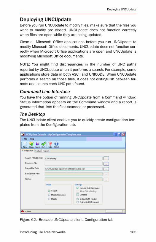
Deploying UNCUpdate
Deploying UNCUpdateBefore you run UNCUpdate to modify files, make sure that the files youwant to modify are closed. UNCUpdate does not function correctlywhen files are open while they are being updated.
Close all Microsoft Office applications before you run UNCUpdate tomodify Microsoft Office documents. UNCUpdate does not function cor-rectly when Microsoft Office applications are open and UNCUpdate ismodifying Microsoft Office documents.
NOTE: You might find discrepancies in the number of UNC pathsreported by UNCUpdate when it performs a search. For example, someapplications store data in both ASCII and UNICODE. When UNCUpdateperforms a search on those files, it does not distinguish between for-mats and counts each UNC path found.
Command-Line InterfaceYou have the option of running UNCUpdate from a Command window.Status information appears on the Command window and a report isgenerated that lists the files scanned or processed.
The DesktopThe UNCUpdate client enables you to quickly create configuration tem-plates from the Configuration tab.
Figure 62. Brocade UNCUpdate client, Configuration tab
Introducing File Area Networks 185
Chapter 9: Brocade UNCUpdate
When you run the configuration to scan for and/or modify UNC pathsin documents, you can click the Status tab to view the operation inprogress. After the operation is completed, you can click the Reporttab to see the list of files processed. Use the Toolbar or File menu toperform operations for the active tab, such as save a configurationtemplate, status information, or a report.
NOTE: The UNCUpdate client can be resized for a better view of statusinformation and reports.
Search and Modify ModesIn search-only mode, the following is a typical task flow:
1. Create a template to search only for UNC paths.
2. Run the configuration. You can click the Status tab in the Consoleto view information about the operation in progress.
3. View the output.
In modify mode, the following is a typical task flow:
1. Create a directives file.
2. Create a template to modify UNC paths.
3. Run the configuration. You can click the Status tab in the Consoleto view information about the operation in progress.
4. View the output
The Directives FileThe directives file specifies the search criteria that UNCUpdate uses tosearch for files. You must specify a directives file when you run UNCUp-date in modify no action or modify mode. (The file is optional when yourun UNCUpdate in search mode.) When you do not specify a directivesfile in search mode, UNCUpdate searches all the files in the path youspecify.
It contains XML instructions detailing how UNCUpdate searches ormodifies files. These instructions include wildcard patterns for fileinclusion/exclusion, the search strings describing the paths to belocated, and scripts or programs required for file modification.
186 Introducing File Area Networks

Deploying UNCUpdate
• Files are selected for inclusion/exclusion based on the <Includes>and <Excludes> tag sections. The following example illustrates theuse of these tags to exclude all EXE, ZIP, JPEG, MPEG and GIFfiles:
<Includes>
<Include name="All files" pattern="*.*"/>
</Includes>
<Excludes>
<Exclude name="All EXE files" pattern="*.exe"/>
<Exclude name="All JPG files" pattern="*.jpg"/>
<Exclude name="All MPEG files" pattern="*.mpeg"/>
<Exclude name="All MPG files" pattern="*.mpg"/>
<Exclude name="All GIF files" pattern="*.gif"/>
<Exclude name="All ZIP files" pattern="*.zip"/>
</Excludes>
The exclude list overrides the include list. If a file matches bothlists, it is excluded. The </Includes> section is not required. If it isnot present, UNCUpdate includes all files.
• Search strings are specified in the directives file through the<MatchTable> tag section. All searches are case-insensitive. Thefollowing example searches files for the strings\\HOUS0023\Users and \\SF0132\Oracle:
<MatchTable>
<Match src="\\HOUS0023\Users"/>
<Match src="\\SF0132\Oracle"/>
</MatchTable>
Introducing File Area Networks 187

Chapter 9: Brocade UNCUpdate
• The <Modules> tag is used to associate a modification modulewith a specific type of file. This tag is only used when a modifyoperation is requested. The following is an example Modulessection:
<Modules>
<Type ext=".xls" method="MSExcel" file="MSExcel.jhe"ProgID="Excel.Application"/>
<Type ext=".txt" method="NVText" file="NVText.jhe"/>
</Modules>
TemplatesYou can create a template to search only for UNC paths or you can cre-ate a template to modify UNC paths. Before you run the template ineither of these modes, you must create a directives file that specifiesthe search criteria (see above).
• First you create and save a configuration template. You create atemplate that will run in search mode because you only want toknow what files contain UNC paths in a location you specify. Youdo not want to modify the files.
• UNCUpdate provides two modify modes: Modify and Modify NoAction. Before you run the template in either of these modes, youmust create a directives file that specifies the search criteria.
• Modify No Action. UNCUpdate scans for valid UNC paths thatmatch the search criteria specified in the directives file.UNCUpdate outputs the list of files to the file you specify in theOutput File Path text box. Use this mode when you want to testthe search criteria specified in the directives file beforeUNCUpdate modifies files.
• Modify. After you test the directives file and make any neces-sary changes, you update the template to run in modify mode.
ReportsAfter you run the configuration template, UNCUpdate shows informa-tion about the files scanned in the Reports tab of the Console. You canalso see status information in the Status tab. After you review thereport of files scanned and status information, you can save the infor-mation into files. Normally, UNCUpdate generates the file in XMLformat, but you can also generate the file in CSV.
188 Introducing File Area Networks
Troubleshooting
Important NotesBefore deploying Brocade UNCUpdate, consider the following:
• UNCUpdate does not support files encoded in UCS-4 UNICODE(32-bit UNICODE typically used only in very complex foreign char-acter sets).
• UNCUpdate does not support Microsoft Office documents that areprotected by internal passwords, protection, and read-onlyoptions. When UNCUpdate encounters these files, they areskipped and information about these files is logged to the XMLoutput file.
• UNCUpdate does not support multi-byte search strings.
• Only UNICODE UCS-2 little endian text files are supported.
• Only Latin character sets are supported.
• If you want to update shortcuts created with Windows XP or Win-dows Server 2003, you must run UNCUpdate on Windows XP orWindows Server 2003 to make the updates.
TroubleshootingStart by checking the health of your UNCUpdate configuration toensure that the following conditions are met:
• Sufficient free space on the drive where UNCUpdate is installed
• Sufficient free space on the drive where the output report file willbe written
• The account used to run the UNCUpdate console has administra-tor privileges on the system where it is installed
The Allow Office Dialogs option enables you to stop running UNCUp-date when a Microsoft Office application opens a dialog box during theprocess of opening a file.
Introducing File Area Networks 189
Chapter 9: Brocade UNCUpdate
Chapter SummaryBrocade UNCUpdate enables organizations to discover, report, and fixfiles containing UNC references, OLE links, and shortcuts to storageresources before and during migration and consolidation. It provideslocation-independent access to file data with the option to update UNCreferences to target data that has been moved to new storageresources. It can also report on files that contain UNC references toother files that are being considered for migration.
Brocade UNCUpdate scans directories for files containing UNC pathsthat might need to be updated to reference items at their new locationas part of a migration. UNCUpdate enables you to locate embeddedUNC paths stored in a file in clear text. UNCUpdate enables you tolocate and modify UNC paths in text files, Microsoft Windows Explorershortcuts, Microsoft Word, Microsoft Excel, and Microsoft PowerPointdocuments. You can perform tasks using the UNCUpdate client or aDOS command-line.
190 Introducing File Area Networks
Introducing File Area Networks
A
ReferenceThis appendix provides reference material for readers who occasion-ally need greater detail. It includes an overview of some of the morenotable items in the hardware and software product lines, and someof the external devices that might be connected to FAN equipment.
Ethernet and IP Network EquipmentConsult the manuals for the products described below for specificinformation and procedures.
Ethernet L2 Edge Switches and HubsIt is possible to use commodity 10/100baseT hubs and/or switches toattach to Ethernet management ports. It is not recommended that youuse hubs for data links.
IP WAN RoutersWhen connecting to a WAN, it is usually necessary to use one or moreIP WAN routers. These devices generally have one or more GigabitEthernet LAN ports and one or more WAN interfaces, running protocolssuch as SONET/SDH, frame relay, or ATM. They almost always supportone or more IP routing protocols like OSPF and RIP. Packet-by-packetpath selection decisions are made at layer 3 (IP).
Figure 63 shows an IP WAN router from Tasman Networks. (http://www.tasmannetworks.com) There are many other vendors who supplyIP WAN routers, such as the Foundry Networks Modular Router shownin Figure 64.
Make sure that the WAN router and service are both appropriate forthe application. Two considerations to keep in mind when selecting aWAN router are performance and reliability.
191

Appendix A: Reference
Figure 63. Tasman Networks WAN Router
Figure 64. Foundry Networks Modular Router
Finally, for redundant deployments it is strongly desirable for a WANrouter to support a method such as the IEEE standard VRRP. Suchmethods can allow redundantly deployed routers to fail over to eachother and load balance WAN links while both are online.
Storage EquipmentRAID ArraysFor the most part, RAID arrays are used to form one or more logical vol-umes based on one or more of the following systems:
RAID 0. Multiple disks are grouped together into a non-redundant vol-ume with a striping algorithm. This is similar to concatenating, butstriping improves performance as well as disk utilization efficiency.The downside to striping is that the loss of any single disk in a RAID 0group will cause the entire group to become inaccessible, and the dataon the volume will be lost. Most RAID 0 implementations use a simpleround-robin method to spread data across disks.
RAID 1. More commonly known as disk mirroring, a RAID 1 set con-sists of two or more physical disks that contain exact duplicates of thesame data. The RAID controller is responsible for setting up and main-taining data synchronization within a RAID 1 set.
192 Introducing File Area Networks
Storage Equipment
RAID 5. This system is like RAID 0 in that data is striped across multi-ple physical disks, but RAID 5 adds a parity element for redundancy.There are a number of different algorithms for laying out RAID 5 vol-umes, but the upshot is that such a volume can lose any single diskwithout causing an outage and data loss for the entire volume.Instead, performance is degraded until the failed disk is replaced. Los-ing a second disk would cause an outage, so there is exposure untilthe replacement is completed. RAID 5 volumes tend to run slower thanother options even when they are not in “degraded” mode because ofthe extra overhead associated with calculating and writing parity datawith each operation.
RAID 1+0; 5+1. Many arrays allow combinations of RAID levels. Forexample, it is possible to configure physical disks in mirrored pairs(RAID 1), then stripe mirrors together (RAID 0). This combines the per-formance of RAID 0 with the reliability of RAID 1. Depending on how itis done, this is known as RAID 0+1 or RAID 1+0. These solutions aremore expensive than RAID 5 because they use more physical diskspace per usable block of data, but they are also faster and more reli-able.
It is also possible to mirror entire arrays together. In this case, eacharray may be presenting one or more RAID volumes, which are thenmirrored or replicated between arrays. This is a popular approach forhigh-end DR solutions, since each array may be located in different cit-ies for redundancy in the event of a major disaster. In this case, it isalso important that each site still has internal redundancy to handlemost events without triggering a DR site-to-site failover. [1+0]+1 and[5]+1 are common approaches for high end DR.
Introducing File Area Networks 193

Appendix A: Reference
194 Introducing File Area Networks

Introducing File Area Networks
B
Namespace RequirementsThere are a number of requirements for using the DFS Namespacewith Brocade MyView.
• The dynamic root must be hosted on the Microsoft Windows 2003Enterprise Edition or 2003 Datacenter Edition. Dynamic domain-based roots can be hosted on Microsoft Windows Server 2003,Standard Edition if you apply the update available throughMicrosoft. The update enables the standard edition to host multi-ple domain-based DFS root. See the Microsoft Web site for moreinformation about this update.
• Users and Groups must be in an Active Directory based domain.
• Administrating a standalone DFS root requires Local Administratorprivileges on the server hosting the root.
• If there are shares in your environment which allow the contentsto be made available offline, and these are going to be availablethrough the namespace, it is important to check to see that the cli-ent operating systems are supported. The supported clients arelisted on the Microsoft’s Web site. Look for the “Distributed File-system Frequently Asked Questions” on www.microsoft.com.
• Microsoft DFS server software (Distributed Filesystem Service“dfssvc.exe”) must be running on the server that hosts the DFSroot. Some Windows Server releases have this service stoppedand disabled by default.
• You must have administrator permissions for the server on whichyou create the standalone or domain-based DFS root.
195

Appendix B: Namespace Requirements
• When creating a domain-based root, Microsoft Active Directorymust already be operational. The account used for MyView musthave administrator permissions for the domain. The permissionsto the Active Directory subtree containing DFS information can bedelegated if it is impossible for the MyView server to run under anaccount with domain administrator privileges.
• When creating domain-based roots, it is strongly recommendedthat you run MyView on a system that is a member of the domainthat hosts the root. Name resolution problems and permissionproblems often manifest themselves in scenarios where theadministrative machine resides in a Windows NT4 domain and isattempting to create a domain-based root in a separate ActiveDirectory domain.
196 Introducing File Area Networks

Introducing File Area Networks
C
WAFS Sizing GuidelinesThis appendix discusses TPA connections and Brocade WAFS CIFS siz-ing guidelines.
Supported TPA Connections with WAFS 3.4Core NodeThe maximum number of optimized TCP connections allowed per Coreis 2500. The maximum concurrent connections does not impact thenumber of supported Edge WAFS nodes. The number of incoming con-nections can be from any number of Edge nodes, as long as themaximum number of supported connections is not exceeded. Beloware some representative calculations for the number of supportedusers:
• 500 Edge users @ 5 connection per user = 2500 connections
• 250 Edge users @ 10 connections per user = 2500 connections
• 100 Edge users @ 25 connection per user = 2500 connections
NOTE: When the number of connections reaches the limit, new con-nections are passed through but not optimized.
Edge NodeThe maximum number of optimized TCP connections per Edge is 500.
Since some applications use more than one connection for client/server communication, the number of users supported does notalways equal the number of connections. Below are some representa-tive calculations for the number of supported users based on thenumber of connections used by an application:
• 500 users @ 1 connection per user = 500 connections
• 100 users @ 5 connections per user = 500 connections
197

Appendix C: WAFS Sizing Guidelines
• 50 users @ 10 connections per user = 500 connections
NOTE: Admission control for inbound TCP traffic to the Edge is limitedto 500 connections. When the number of connections reaches thelimit, new connections are passed through but not optimized. TheEdge node optimizes new incoming connections after the number ofconcurrent connections drops below 490 connections.
WAFS Sizing Guidelines for CIFS Following are sizing guidelines for Common Internet File System (CIFS),a standard remote file-system access protocol for use over theInternet.
Core Node• Single Core for every 60 Edges nodes, based on a Microsoft envi-
ronment with Microsoft Office applications.
• If you use TPA, a single Core for every 50 Edges nodesrecommended.
• Maximum of 5000 concurrent sessions per Core. Although a Corenode can support a maximum of 5000 concurrent sessions, thenumber of Edge nodes connected to a Core node is limited to 60.
Edge Node• 250 concurrent sessions per Edge node. A concurrent session
maps to 2 or 3 branch office users; this number can vary by plusor minus 30 percent.
• Includes Print, DC, DNS/DHCP services (4 GB of memory)
• A maximum of 8 printers for each Edge node
• CIFS connections are established per workstation, per mappeddrive, but are removed after 15 minutes of inactivity.
• CIFS sessions assume a typical user mix of directory browsing, filefetches, and “think time.”
WAN Throughput• 8 Mb/sec for raw WAN throughput
• 24 Mb/sec for effective WAN throughput
198 Introducing File Area Networks

Introducing File Area Networks
Glossary
ANSI American National Standards Institute is the governing body forstandards in the United States.
API Application Programming Interfaces provide a layer of abstractionbetween complex lower-level processes and upper-level applicationsdevelopment. They facilitate building complex applications by provid-ing building blocks for programmers to work with.
ASIC Application-Specific Integrated Circuits are fixed-gate microchipsdesigned to perform specific functions very well.
ATM Asynchronous Transfer Mode is a cell-switching transport usedfor transmitting data over CANs, MANs, and WANs. ATM transmitsshort fixed-length units of data. Characterized by relatively high perfor-mance and reliability vs. switched IP solutions.
Bandwidth Transmission capacity of a link or system.
Broadcast Transmitting to all nodes on a network.
Bridge Connects segments of a single network
Brocade Founded in 1995, Brocade rapidly became the leading pro-vider of Fibre Channel switches. At the time of this writing, thecompany carries switches, directors, multiprotocol routers, and a suiteof File Area Networking products.
CAN Campus Area Networks tend to be under a kilometer or so in size.They are distinguished from LANs in that those tend to be in the ~100meter range, but more importantly CANs cross between buildings. Thischaracteristic tends to imply thinner cabling, potentially higher speedsrunning over that cabling, and higher locality.
CLI Command line interfaces are text-oriented methods of managingdevices.
199

Glossary
COS Class Of Service represents connection quality: a profile forattributes such as latency and data-rate.
CRC Cyclic Redundancy Check is a self-test for error detection andcorrection. All Brocade ASICs perform CRC checks on all frames toensure data integrity
CSMA/CD Carrier Sense Multiple Access with Collision Detectiondefines how Ethernet NICs behave when two or more attempt to use ashared segment at the same time
CWDM Coarse Wave Division Multiplexer. See also WDM on page 207and DWDM on page 201.
Dark Fiber A leased fiber optic cable running between sites character-ized by not having a service provided on the wire by the leasingcompany. All services are provided by the customer.
DAS Direct Attached Storage is the method of connecting a singlestorage device directly to one and only one host. In the enterprise datacenter, DAS is obsolete and has been replaced by storage networking.
DFS Microsoft Distributed File System consists of software residing onnetwork servers and clients that transparently links shared folders ondifferent file servers into a single namespace for improved load bal-ancing and data availability. NOTE: This should not be confused withTransarc DFS product, which is a separate distributed file system prod-uct that is not interoperable with the Microsoft product.
DFS link Located under the DFS root. The DFS link forms a connectionto one or more shared folders, DFS links, or another DFS root.
DFS namespace The logical view of shared file resources seen byusers and the roots and links which make up the physical view. Seealso Logical namespace on page 203 and Physical namespace onpage 204.
DFS root The share at the top of the DFS topology. The starting pointfor the DFS links and shared folders that make up the namespace.
Directives file In Brocade UNCUpdate, specifies the search criteriaused to search for files; must be specified when you run UNCUpdate inmodify no action or modify mode. (The file is optional when you runUNCUpdate in search mode.)
200 Introducing File Area Networks

Glossary
Display name The default value or name for a user that appears in thedisplay name field in Active Directory or the default name of a folder orshare and the DNS name of a machine. When you want thenamespace to show the display name of an item, select the appropri-ate item:
(1)Resource_Machine(2)Resource_Name(3)Resource_Share(4)Grantor_Display Name(5)User_Name.
Display name rule Criteria you specify to change the display name of auser, share, folder, or machine.
DoS Denial of Service attacks may be launched deliberately by ahacker or virus, or may happen accidentally. Either way, the result isdowntime. The best approach for preventing DoS attacks in a SAN is tofollow security best-practices, and to use redundant (A/B) fabrics.
Domain-based root A DFS root that has its configuration informationstored in Active Directory. The root can have multiple root targets,which offers fault tolerance and load sharing at the root level.
DWDM Dense Wave Digital Multiplexer. Allows more wavelengths thana CWDM. See also WDM on page 207 and CWDM on page 200.
Dynamic root Roots created by MyView on the host servers you spec-ify. MyView creates the roots to optimize the namespace by reducingthe number of links in the entry point root and consolidating repeatedlink patterns. For example, if a namespace will contain more links inthe entry point root than DFS allows, MyView automatically createsanother root to balance the links between the entry point root and thedynamically created root.
Entry point root The main root of your DFS namespace. The root canbe standalone or domain-based. It can be hosted on Windows 2000,Windows Server 2003, or an NT4 server. The root must be empty.Roots dynamically created by MyView to scale the namespace are ref-erenced by this root.
Ethernet The basis for the widely implemented IEEE 802.3 standard.Ethernet is a LAN protocol that supports data transfer rates of 10Mb/sec. It uses the CSMA/CD to handle simultaneous access to sharedmedia. Fast Ethernet supports data transfer rates of 100 Mb/sec, andGigabit Ethernet supports 1 Gb/sec and there is also an emerging 10Gb/sec standard.
Introducing File Area Networks 201

Glossary
FC Fibre Channel is the protocol of choice for building SANs. Unlike IPand Ethernet, FC was designed from the ground up to support storagedevices of all types.
FPGA Field Programmable Gate Arrays are similar to ASICs, exceptthat their hardware logic is not fixed. It is possible to reprogram anFPGA in the field. Generally more expensive and possibly slower thanan ASIC, but more flexible.
Frame Data unit containing a Start-of-Frame (SoF) delimiter, header,payload, CRC and an End-of-Frame (EoF) delimiter. The payload can befrom 0 to 2112 bytes, and the CRC is 4 bytes. When operating acrossEX_Ports, the maximum payload is 2048 bytes.
FRS The File Replication service (FRS) is a multi-threaded, multi-mas-ter replication engine that replaces the LMREPL (LanMan Replication)service in the 3.x/4.0 versions of Microsoft Windows NT. Windows2000 domain controllers and servers use FRS to replicate system pol-icy and login scripts for Windows 2000 and down-level clients. FRS canalso replicate content between Windows 2000 servers hosting thesame fault-tolerant Distributed File System (DFS) roots or child nodereplicas.
Hot Swappable Component that can be replaced while the system isunder power
IEEE Institute of Electrical and Electronics Engineers defines stan-dards used in the computer industry
IETF Internet Engineering Task Force is the group that develops proto-cols for the Internet
ILM Information Lifecycle Management is the concept that informa-tion can be matched to resources most appropriate for its value at anypoint in its lifetime
IP Internet Protocol is the addressing part of TCP/IP
IPSec Internet Protocol Security is a set of protocols that provide net-work layer security. This is often used to create VPNs. It may be used toauthenticate nodes, encrypt data, or both.
LAN Local Area Network; a network where transmissions are typicallyunder 5km.
Latency The period of time that a frame is held by a network devicebefore it is forwarded, ant the time that it sits on a cable betweendevices. (The latter is usually only significant on long distance links.)
202 Introducing File Area Networks
Glossary
Logical namespace The view of the namespace that users see whenthey access their data through the namespace.
LUN Logical Unit Numbers are used to identify different SCSI devicesor volumes that all have the same SCSI ID. In Fibre Channel, LUNs dif-ferentiate devices or volumes that share a WWN/PID address.
MAN Metropolitan Area Networks typically cover longer distances thanLANs, but shorter distances than WANs. MANs may connect differentcampuses within a city, or between cities in a closely linked group. Thesize tends to be that of a metropolitan region: they can be tens ofmiles in radius, but cannot generally be more than a hundred miles orso. They tend to be provided by a single carrier from end-to-end,whereas WANs may involve different carriers.
MMF Multimode Fiber is a fiber-optic cabling specification that allowsup to 500-meter distances between devices. MMF cables can haveeither 50 or 62.5 micron optical cores. Generally used with SWLmedia.
MTBF Mean Time Between Failures is the average time between thefailure of any component in a system. This equates to how often ser-vice needs to be performed, and does not necessarily refer to howoften availability is impacted.
MTTR Mean Time To Repair is the average amount of time it takes torepair a failed component.
Multicast Transmitting to a set of nodes on a fabric. More than one(which would be unicast) and less than all (which would be broadcast).This is often used in video applications.
Multiprotocol A device capable of using more than one protocol. Forexample, a router that has both Ethernet and Fibre Channel interfaceswould be a multiprotocol router.
Namespace See DFS namespace on page 200.
Namespace path The location of an item in the namespace. The fol-lowing example is the location of “LinkA” in the logical folder “L” in theroot “MyViewRoot” hosted on the server “maravirt2k3.npb.com.”\\maravirt2k3.npb.com\MyViewRoot\L\LinkA
NAS Network Attached Storage is a common name for network filesystem (usually CIFS and/or NFS) servers that are specially optimizedfor that task. Often the only difference between a NAS storage deviceand a UNIX NFS server, for example, is packaging.
NIC Network Interface Cards connect a host’s bus to a network.
Introducing File Area Networks 203
Glossary
OEM Original Equipment Manufacturers buy Brocade products, inte-grate them with other storage products such as disk drives, tapelibraries, and hosts, and resell them under their own brand names.
Physical namespace The view of a namespace that shows the config-uration of the namespace, such as roots, links, and logical folders.
Publish The process by which MyView generates a namespace. Thefirst time a namespace is generated, MyView creates all the roots andlinks that make up the namespace. Subsequent changes to thenamespace are incremental. Only the roots and links that change areupdated in the namespace.
QoS Quality of Service is a somewhat generic term that can refer to amechanism that can guarantee priority, bandwidth, latency, error rate,and similar characteristics for the network path between nodes.
RAID Redundant Array of Independent (formerly Inexpensive) Disks. Aset of disks that looks like a single volume. There are several RAID lev-els used to solve different storage performance, scalability, andavailability problems. Most are fault-tolerant and/or high performance.
RAS Reliability Availability and Serviceability collectively refers to theoverall quality of a component, device, or network. Factors that influ-ence RAS include things like the MTBF and MTTR of components,software architecture, and redundant deployment strategies.
Redundancy Having multiple occurrences of a component to maintainhigh availability
Relationship The association based on permissions between users/groups and the shares and folders to which the users/groups haveaccess. A view must specify one relationship for MyView to calculatethe namespace.
RETMA Radio Electronics Television Manufacturers Association in thecontext of storage networks is a standard specification for data centerracks. A typical rack-mountable network device is designed to fit into astandard 19 inch RETMA rack, and its height is usually referred to interms of RETMA “rack units.” (Each unit is about 1.75 inches forobscure historical reasons.)
Root replica See Root target on page 204.
Root target The share that contains the configuration of a root.Domain-based roots can contain multiple root targets. The configura-tion of a domain-based root is replicated on all its root targets for faulttolerance. A standalone root contains only one root target.
204 Introducing File Area Networks
Glossary
Router Device for interconnecting at least two different networks intoan internetwork.
SAN Storage Area Networks link computing devices to disk or tapearrays. Almost all SANs at the time of this writing are Fibre Channelfabrics.
SCSI Small Computer Systems Interface as originally defined was afamily of protocols for transmitting large blocks up to of 15-25 meters.SCSI-2 and SCSI-3 are updated versions of this. As the direct attach-ment of storage moved to a network model, SCSI has been mapped toprotocols such as FC and IP.
SCSI Inquiry SCSI command that generally causes a target to respondwith a string telling the requester information such as its make, model,and firmware version. Used by the SNS to further identify Fibre Chan-nel devices. The iSCSI Gateway Service inserts IP and IQN strings usingthis SNS field.
Server pool Contain the servers that will host dynamic roots. When apool contains multiple servers, the root configuration of each dynamicroot hosted on a server is replicated on all the other servers in thepool, providing fault tolerance.
Shares and folder collection Shows all the shares and/or folders in amachine or domain you specify.
SilkWorm Registered trademark for the Brocade family of switches,directors, and routers. Use of this term has been discontinued, forexample, the SilkWorm 48000 Director is now simply referred to as theBrocade 48000 Director.
SMF Single Mode Fiber is a cabling specification that allows 10km oreven greater distances. SMF cables have nine micron optical cores.Generally used with either LWL or ELWL media.
SONET/SDH Synchronous Optical Networks are used in MANs andWANs. FC can be mapped to SONET/SDH. Characterized by high per-formance and reliability. The analogous service is called SDH in othercountries.
Standalone root A DFS root that has its configuration informationstored locally on the host server. The root has a single root target.When the root target is unavailable, the namespace is inaccessible.Data targeted by the namespace is still reachable either by virtue ofcached DFS referrals or direct access to the storage resources.
Storage Device used to store data like disk or tape
Introducing File Area Networks 205
Glossary
Storage subsystem See Subsystem on page 206.
Storage virtualization See Virtualization on page 207.
Subsystem Synonym for storage device. Often external. On a SAN,may be shared between many compute nodes.
SWL Short Wavelength Laser transceivers based on 850nm lasers aredesigned to transmit short distances. This is the most common type ofmedia.
T11 ANSI committee chartered with creating standards for data move-ment to/from central computers
Tapestry Trademark for a Brocade family of upper-layer products,which included FAN products. Use of this term has been discontinued.
Target Disk array or a tape port on a SAN
TCP/IP Transmission Control Protocol over Internet Protocol is the com-munication method for the Internet
TCP Transmission Control Protocol is a connection-oriented protocolresponsible dividing a message into packets, passing them to IP, andreassembling them into the original message at the other end. Detecterrors / lost data and triggers retransmission if needed.
TCP Port Addresses component that allow nodes to access a specificservice for a given address. There are many well-known ports thatallow standard upper-layer protocols like HTTP to work: Web serversknow to listen on the same port, and Web clients know to attach tothat port.
Topology The physical, logical, or phantom arrangement of devices ina networked configuration
Transceiver Device that converts one form of signaling to another fortransmission and reception. Fiber-optic transceivers convert from opti-cal to electrical.
Tunneling Technique for making networks interact where the sourceand destination are on the same type of network, but there is a differ-ent network in between
ULP Upper-Level Protocols run on top of FC through the FC-4 layer.Examples include SCSI, IP, and VI.
Unicast Sending a frame between just two endpoints. Distinguishedfrom broadcast and multicast where one transmitter has multiplereceivers.
206 Introducing File Area Networks

Glossary
Virtualization The manipulation and abstraction of devices such asdisks and tapes. Generally performs functions above and beyondthose performed by traditional RAID applications. Examples includeLUNs that span multiple subsystems, LUN over-provisioning where thesize of a presented LUN is larger than the underlying storage capacity,and application-invisible data replication and migration. FANs virtual-ize file systems.
VLAN Virtual Local Area Networks allow physical network devices to becarved into smaller logical segments. This is done in IP/Ethernet net-works to prevent broadcast storms from creating instability.
VPN Virtual Private Networks use encryption to create tunnels throughpublic networks, so devices on one either end appear to be located ona physically isolated network.
VRRP Virtual Router Redundancy Protocol allows one router to takeover the duties of another in the event of a failure. It can be thought ofas a router clustering method.
WAN Wide Area Networks span cities, states, countries, and even con-tinents. They tend to have higher delays due to their longer distances.WANs are often used by storage networks in disaster tolerance orrecovery solutions.
WAFS Wide Area File Services is a product designed to optimize cost,manageability, reliability, and performance of storage volumes inbranch offices.
WDM Wavelength Division Multiplexers allow multiple wavelengths tobe combined on a single optical cable.
xWDM See DWDM on page 201 and CWDM on page 200.
Introducing File Area Networks 207

Glossary
208 Introducing File Area Networks