
Intro to Cryogenics
80
INTRODUCTION TO LABORATORY CRYOGENICS By M.N. Jirmanus, Ph.D. Janis Research Company, Inc. 2 Jewel Drive Wilmington, MA 01887 Tel: (978) 657·8750 Fax: (978) 658·0349
Transcript of Intro to Cryogenics

INTRODUCTION TO LABORATORY
CRYOGENICS
By
M.N. Jirmanus, Ph.D.Janis Research Company, Inc.
2 Jewel DriveWilmington, MA 01887
Tel: (978) 657·8750Fax: (978) 658·0349

.'
Preface
This work is meant for scientists, students, and laboratorypersonnel who have had little or no experience in cryogenics.It concentrates primarily on cryogenic systems that arecommercially available for operation between 1.5 K and 300 K(room temperature). For those users who want to design and buildtheir own equipment, or who are interested in a more detailedanalysis of cryogenic systems, a number of excellent referencesare listed at the end of this booklet.
The first section discusses the vacuum requirements forlaboratory dewars and variable temperature cryostats. This isfollowed by a section on liquid helium and liquid nitrogen dewars,and another section on variable temperature cryostats. The nextsection concentrates on superconducting magnets that are combinedwith variable temperature cryostats for laboratory experiments,requiring relatively large magnetic fields.
section five describes closed cycle refrigerator cryostats thatrequire no liquid cryogens, and the last section concentrates onexperimental techniques, thermometry, and automatic temperaturecontrol. This last section also includes a few tables that arehelpful in estimating heat loads on the cold stage and attachedsample. More detailed information and experimental data areavailable from the referencea.listed.at.the end of this section.
The figures (drawings) spread throughout sections 2 through 5,show a variety of dewar and cryostat designs, based primarily onour experience at Janis. These designs have evolved over a 30year period, and represent a typical cross section of laboratoryunits that can be used for a wide variety of experiments. Manyother configurations with differing designs are of course available,but were not included due to lack of space. The designs that arediscussed in this work should, however, address most standardexperimental requirements for work at low temperatures.
i i

r,, .
r
~

i I
CONTENTS
section 1. Vacuum Requirements
section 2. Liquid Helium and Nitrogen Dewars
A. Welded Dewars
B. Detachable Tail Dewars
C. Tail Extensions1. Immersion Tails2. Tails for Sample in Vacuum
section 3. Variable Temperature Cryostats
Page
1
5
5
9
121216
19
A. Thermal Impedance Cryostats 20
B. Exchange Gas Cryostats 201. Exchange Gas Inserts for Open Neck Dewars 222. Exchange Gas Inserts for Detachable Tail Dewars 24
i. Sample in Exchange Gas 24ii. Sample in Vacuum 27
C. continuous Flow Cryostats1. Flow Cryostats with Detachable Tail Dewars2. Flow Cryostats for Open Neck Dewars3. continuous Transfer Cryostats
i. Sample in Vacuumii. Sample in Vapor
section 4. Superconducting Magnet Systems
A. Variable Temperature-Top Loading-Dewars-
B. optical Access Straight Solenoid Systems
C. optical Access Split Solenoid Systems
D. Magnet Systems for Special Applications
section 5. Closed Cycle Refrigerator systems
A. Cold Finger Cryostats
B. Exchange Gas cryostats
section 6. Experimental Techniques and Data1. Cooldown of Cryostats and Samples2. Thermometry and Temperature Control
Thermometer InstallationAutomatic Temperature Controllers
3. Useful cryogenic Data and References
iii
272831333537
39
42
44
46
48
50
52
54
575759596365

FIGURES AND TABLESPage
Figure 2.1 Open Neck Liquid Nitrogen Dewar 6
Figure 2.2 Open Neck Liquid Helium Dewar 8
Figure 2.3 Detachable Tail Dewar/Open Nitrogen Reservoir 10
Figure 2.4 Detachable Tail Dewar/Closed Nitrogen Reservoir 11
Figure 2.5 Immersion TUbular Tail 13
Figure 2.6 Immersion Optical Tail 14
Figure 2.7 Cold Finger/Sample in Vacuum 17
Figure 3.1 Thermal Impedance Cryostat 21
Figure 3.2 Exchange Gas Insert 23
Figure 3.3 optical Exchange Gas cryostat 25
Figure 3.4 Sample in Vacuum Exchange Gas Cryostat 26
Figure 3.5 Flow Cryostat with Detachable Tail Dewar 29
Figure 3.6 Flow Cryostat Insert for superconducting Magnet 32
Figure 3.7 Flexible Transfer Line for Continuous Transfer 34
Figure 3.8 continuous Transfer Cold Finger Cryostat 36
Figure 3.9 continuous Transfer Sample in Vapor Cryostat
Figure 4.1 Variable Temperature-Magnet· Support Cryostat
Figure 4.2 Magnet Cryostat with Bottom optical Access
38
43
45
Figure 4.3 Magnet Cryostat for Magneto-Optical Experiments 47
Figure 5.1 Closed Cycle Refrigerator cryostat 53
Figure 5.2 Exchange Gas Refrigerator Cryostat
Table 6.1 Average Thermal Conductivity of Materials
Table 6;2 'Experimental Values of EmissivitiesTable 6.3 Thermal Expansion Data.
55
67
69'.;. .. '.,.
Table 6.4 Experimental Data for Helium and NitrogenTable 6.5 "Densities of S/S, CU & Al
Figure 6.6 Enthalpy of SIS, CU, & Al
Figure 6.7 Amount of Helium to Cool Common Metals
iv
70
71
72
•
1. VAcuuM REQUIREMENTS
A liquid hel~um or nitrogen dewar usually consists of one ormore reservo~rs containing the cryogen. The cryogenreservoirs are surrounded by a jacket which is evacuated inorder to reduce (or eliminate) the conductive heat load dueto any gases inside this jacket. This conduction will causecondensation of moisture around the outside of the dewar,and more importantly, result in an unacceptable heat load onthe cryogen reservoirs(s). Thus, most dewars and transferlines are supplied with an evacuation valve, located on theouter jacket, for pumping out the dewar vacuum.
Liquid nitrogen shielded, liquid helium dewars will usuallyhave two interconnected vacuum jackets surrounding thehelium and the nitrogen reservoir. In such dewars, theliquid helium reservoir will be surrounded by a liquidnitrogen reservoir, in order to reduce the radiational heatload into the helium reservoir. Since this heat load isproportional to the fourth power of the absolutetemperature, a liquid nitrogen reservoir at 77 K willradiate significantly less than an equivalent surface at300 K (room temperature). Other liquid helium dewars andtransfer lines are supplied with multi layer insulationsurrounding the cryogen reservoir (or inner line), and onlyone evacuated jacket. MUltilayer insulation (MLI) orfloating radiation shields reduce the radiational heat loadinto the liquid helium space, as the inner layers are cooledby the escaping helium vapor in a properly designed dewar.Liquid nitrogen dewars will contain only one vacuum jacket,and may also contain MLI for reducing the radiational heatload from room temperature on to the nitrogen reservoir.
The pressure in the vacuum jacket of dewars and transferlines should be reduced to at least 10.4 torr, andpreferably one or two orders of magnitude lower. At roomtemperature, a pressure of 10.4 torr results in a mean freepath of approximately 100 cm, (Ref. 1, Ch VII) much largerthan the typical separation between the outer and innerwalls of most research dewars. This is the region ofmolecular flow, where the dominant type of collisionprocesses are between the molecules and the walls of thevacuum jacket(s). The heat load in a typical cryostat (from77 K to 4.2 K) due to helium gas at a pressure of 10.5 torris a few milliwatts (Ref. 1, Ch VII). It is thus criticalto reduce the pressure inside the vacuum jacket to the 10.5
or 10.6 torr region.
A variety of pum?ing stations are available for obtainingpressures of 10· to 10.6 torr. The most commonly usedstations consist of a diffusion pump, backed by a rotarypump, with a liquid nitrogen cold trap to prevent oil vaporsfrom back-streaming into the vacuum jacket. A 3" diffusion
1
pump is generally sufficient for most laboratory dewars andcryostats. Other pumping stations with turbo molecularpumps, backed by a rotary pump are also used. Turbomolecular pumping stations have a small advantage overdiffusion pumping stations, since the turbo molecular pumpcan be activated simUltaneously with the backing rotarypump. On the other hand, a diffusion pump should not beturned on until the back up rotary pump has reduced thepressure to about 5 x 10⁻² torr, in order to prevent theoxidization of the oil in the diffusion pump. Turbomolecular pumps are, however, more expensive than diffusionpumps.
Rotary pumps are occasionally used (in line with a coldtraf) to reduce the pressure to 10-2 torr (single stage) or10- torr (good double stage). Such pressures are notadequate for operation of liquid nitrogen dewars orcryostats that operate between 77 and 300 K. Occasionally,however, they will give satisfactory performance with liquidhelium dewars, if the dewar evacuation valve is sealed justbefore the liquid helium is transferred into the dewar.This is because the liquid helium reservoir will cryopumpthe dewar vacuum and result in a pressure of 10-6 torr,which is quite adequate. If this set-up is used with somevariable temperature cryostats, then once the cryostat isheated above 80 K, outgassing will occur, and could resultin poor performance due to the deteriorating vacuum level.
Most pumps start out at a high pumping speed (usually quotedby the manUfacturer) then as the pressure drops in thechamber, so does the speed of the pump. A quantity that isvery useful in describing the system being evacuated, is thethroughput. This is defined as the quantity of gas inpressure volume units, flowing per second through aspecified cross section of the system [Q = d(PV)/dt]. (Ref.2, Ch. 2) For steady state flow. in..a.pipe .withno sources .orsinks, the throughput of gas between two points isproportional to the pressure difference between thosepoints. this may be expressed as:
1.1
where U is the conductance of the section between the twopoints. When several sections of a pumping system areconnected in series, then the combined conductance U. isgiven by,
U -, = U -, + U -, + U -,s , 2 3 • • •
Now the speed (S) of a pump (for a particular gas) isdefined as the ratio of the throughput at the pump entrance,to the pressure of that gas. Thus
S = Q/P.
2
1.2

When one attaches a pump to the evacuation valve, through aspecific pumping line, then the throughput of gas at thepump is the same as the throughput of gas leaving the vacuumjacket. Since the pressure at the pump is lower than thatat the vacuum jacket (when dewar evacuation is in progress),this results in an effective pumping speed (Sd) at thedewar, where the pressure is Pd, obtained from the relation:
1.3
1.4
When this is combined with 1.1, the resultant effectivepumping speed at the dewar becomes
Sd = 5/ (1+5/U)
The conductance of a long tube (length L much greater thanthe radius r) for air at room temperature is approximately100 rl/L (Ref. 1, Ch. 1) liters/second (with rand Lexpressed in cm). If one is using a 1. 5" diameter x 5' longevacuating line, this would result in 4.5 lit/secconductance. Thus, using a 27 cubic foot/minute (cfm) pump(12.7 liters/second) at one end of this evacuating line; theeffective pumping speed at the other end would drop to 5 cfm(3.3 lit/sec).
A variety of vacuum gauges can be used at different pressureranges. A thermocouple gauge is often used with rotarypumps in the range of 1 atmosphere to 10-3 torr. For lowerpressures (10.3 to 10.7 torr) an ionization gauge is commonlyused. These gauges are usually located at the pump opening,and it is important to note that depending on the pumpingline connecting it to the dewar, the pressure at the dewarcan be significantly higher (at room temperature). Thus inthe above example of the 5' .line, using equation 1.3, onegets a pressure at the end of the line 3.8 times that of thepressure at the pump.
Once the vacuum jacket of the dewar is evacuated, and thedewar cooled (to LNz or LHe temperatures), the pressure inthe cold region will drop. An approximate relation thatholds under these low pressures is that the pressure willvary in proportion to the square root of the absolutetemperature (P/jT = constant) (Ref. 1, Ch. 1). It istherefore recommended that when liquid helium is transferredinto a dewar, the dewar evacuation valve should be closed.If this is not done, the cryopumping that occurs due to theliquid helium may pump back oil vapors (from the pump) intothe vacuum jacket. This is especially true if the pumpingstation used does not have a liquid nitrogen cold trap.This will contaminate the vacuum jacket and result in ahigher heat load, and poor dewar performance.
3

Very often, the design of metal dewars requires the use ofthin walled (0.01" - 0.06" thick) stainless steel tubing forthe helium (or nitrogen) reservoirs. These reservoirs aretherefore not designed to withstand a pressure difference ofone atmosphere on their exterior surface and will thuscollapse. They are however designed to withstand anatmosphere pressure difference on their inner surface. Apotentially dangerous situation can occur if one evacuatesthe helium reservoir while the outer jacket is atatmospheric pressure. It is thus best to always maintainthe vacuum jacket under vacuum, and preferably install apressure gauge on this jacket to indicate the pressureinside the jacket. It is also good to avoid introducinghelium gas inside the vacuum jacket since helium gas has ahigh thermal conductivity (about 12 times that of nitrogengas), will not condense at 4.2 K, and is generally moredifficult to remove than air or nitrogen. This isespecially true in transfer lines and vapor shielded dewarsthat have MLI in their vacuum jackets.
4
2. LIQUID BELlUM AND NITROGEN DEWARS
As mentioned earlier, liquid helium and nitrogen dewarsusually consist of one or more reservoirs, surrounded by avacuum jacket which isolates these reservoirs from roomtemperatures. Although some dewars are manufactured fromglass or epoxy-fiberglass and aluminum, the most reliableones are made from stainless steel. This is primarily dueto the fact that stainless is very rugged, has a relativelylow thermal conductivity and can be easily and permanentlyjoined to similar or dissimilar (copper, brass, etc.) metalsby welding (in an inert gas atmosphere) or silver soldering.Such joints can withstand many cycles between roomtemperature and helium (or nitrogen) temperature and stillremain leak tight after years of use.
A. Welded Dewars
The simplest dewars will have an all welded constructionwith direct access to the cryogen reservoir through the topof the dewar. These dewars are used for storage or fordirectly immersing the sample in the cryogen. Such dewarswill have an evacuation valve for evacuating the spacesurrounding the cryogen reservoir, and also a safetypressure relief valve to protect the vacuum jacket should aninternal leak develop. Such a leak will result in the coldcryogen entering the vacuum jacket, warming up after contactwith the room temperature wall, and expanding. This couldresult in a high pressure build up in the vacuum jacket. Asafety pressure relief valve set to open at 2 to 5 Ib/in2
(psi) above atmospheric pressure, will safely vent theleaking gas to the outside of the vacuum jacket and preventany dangerous pressure build up.
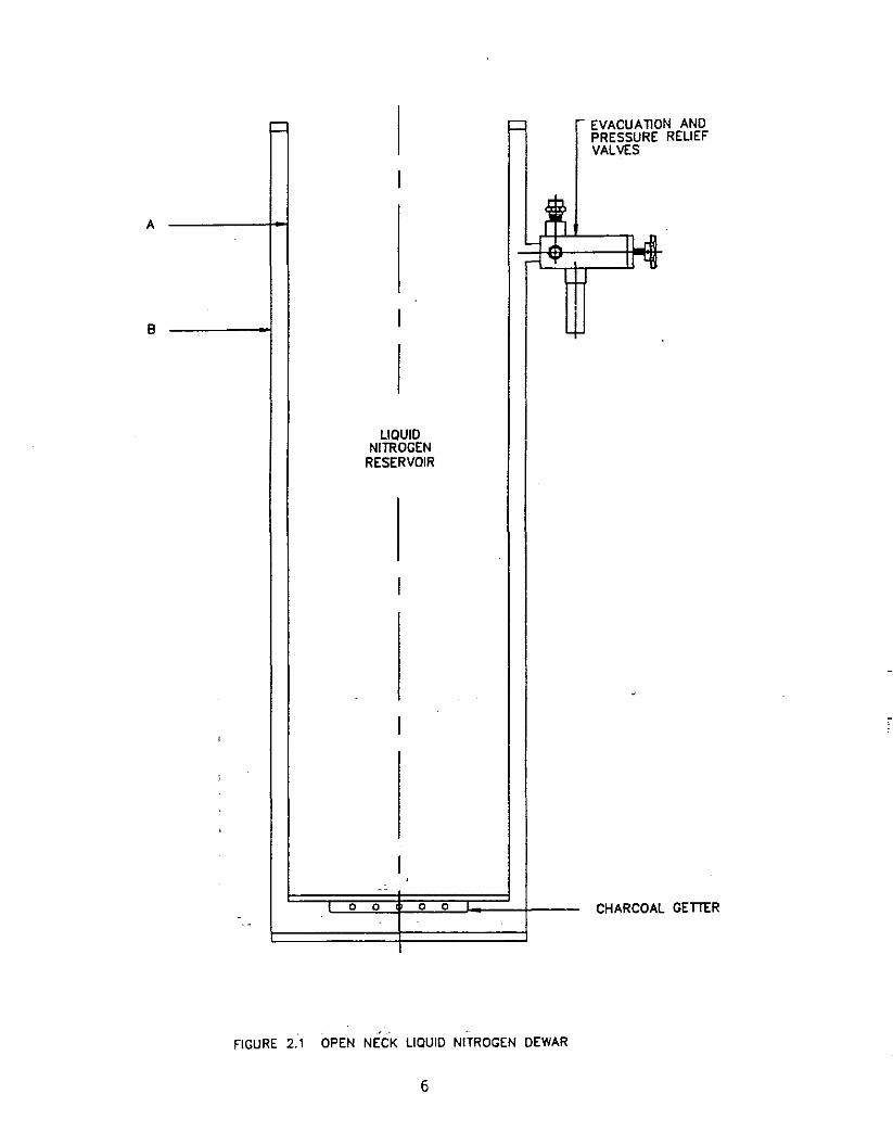
A simple open neck, "bucket type" liquid nitrogen dewar isshown in Fig. 2.1. The liquid nitrogen reservoir is acylinder with diameter A, and the outer jacket is aconcentric cylinder of diameter B. The space between A andB is evacuated through the evacuation valve, which should bea good bellows sealed valve. The charcoal getter located inthe vacuum jacket is cooled by the liquid nitrogen, andhelps maintain a good vacuum over extended periods ofoperation. Such a dewar can be used to immerse a sample orany insert directly in liquid nitrogen.
5
GETItR
NANDRELIEFi= = ~ EVACUAllO
PRESSUREVALVES
I
~ILr2-j ..I.
-l .,..IrLfl
I ~
LIQUIDNITROGEN
RESERVOIR
I
-I,
,
I--
0 0 0 0 CHARCOAL- -
B
A
FIGURE 2.1 OPEN NECK L1aUID NITROGEN DEWAR
6

Figure 2.2 shows an open neck (bucket type) liquid heliumdewar where the helium reservoir is a cylinder of diameterA. This is surrounded by a nitrogen reservoir (annularspace between tubes B & C) which shields the surface of thehelium reservoir from room temperature radiation. The spacesurrounding the helium reservoir (between A & B), and thespace surrounding the nitrogen reservoir (between C & 0) isevacuated through the evacuation valve on the outer jacket(diameter 0). These two spaces are connected through a slotin the radiation shield which is bolted to the bottom of thenitrogen reservoir. Thus both spaces are evacuatedsimultaneously through the evacuation valve. The radiationshield bolted to the bottom of the nitrogen reservoir isusually made from a good thermal conductor (aluminum orcopper), while the rest of the dewar is made from stainlesssteel. Tube A has a wall thickness of about 0.025", inorder to reduce the conductive heat load into the liquidhelium. The helium reservoir should never be evacuatedbefore ensuring that the main dewar is under vacuum.
When the nitrogen reservoir is filled with liquid nitrogen,the Flange F and the upper portion of tube A will be at77 K. This intercepts the conductive heat load into thehelium reservoir from room temperature along the neck of thehelium reservoir (top portion of tube A). Generally, thehelium reservoir can then be filled up to about 10" belowflange F, leaving an empty ullage volume on top of thehelium reservoir. This leaves a reasonable distance betweenpoints at 77 K and 4 K and results in an acceptableconductive heat load into the helium reservoir. Thecapacity of the liquid helium reservoir is thus the totalvolume contained within the cylinder (diameter A) less thevolume of the ullage 6pace.
Any insert placed in the helium reservoir should containseveral radiation baffles (usually made from copper) in theneck region, with a diameter 0.25" less than that of theneck. These baffles are cooled by the escaping helium vaporand thus intercept the radiational heat load from the roomtemperature top flange of the insert (which can be verylarge). The baffles also force the vapor to make moreintimate contact with the helium reservoir neck, thusintercepting about 85% of the conductive heat load down theneck (when properly designed).
The inserts that are placed into this type of dewar could bea simple immersion type or a variable temperature cryostat.The former will usually place the sample in direct contactwith the liquid helium at 4.2 K or lower. The lowertemperatures are achieved by reducing the pressure on top ofthe helium through an appropriate pumping port. variabletemperature inserts (as will be discussed later) will placethe sample in an environment where its temperature can beraised above 4.2 K (usually to room temperature or higher),
7

OGEN
GETTER
SHIELD
llON ANDE RELIEF
C =:J
- = -EVACUA
I PRESSURVALVES
~~.!I-j
r-l 1"fJ
tI
,UQUIDHELIUM
RESERVOIR
I,LIQUID NITRRESERVOIR
I
I~ hL't' o 0 o 0 RADIATION
---- CHARCOAL
C
D
A
B
F
FIGURE 2.2 OPEN NECK LIQUID HELIUM DEWAR
8

or reduced below 4.2 K (to 1.5 K, 0.3 K or a few milli- K).These inserts should always be supported from thin walledstainless steel or epoxy fiberglass tubing, in order toreduce the conductive heat load into the helium reservoir.This is due to the fact that the latent heat of vaporizationof liquid helium is extremely small (1 watt will boil off1.4 liters LHe/hr when absorbed by the liquid). Also anywiring that enters the helium reservoir should be as thin aspossible, and (whenever possible) made from poor thermalconductors such as manganin, phosphor bronze, stainlesssteel, etc. In all cases one should either intercept someof the heat load with liquid nitrogen, which has a muchhigher heat of vaporization (1 watts boils off 22.4 milliliters LN~/hr), or make use of the tremendous cooling powerof the bo~ling helium vapor between 4.2 K and 300 K (about80 times the latent heat of vaporization of LHe at 4.2 K).
Inserts that contain superconducting solenoids which need tobe immersed in liquid helium, are also placed in these"bucket type" dewars. Special counter-flow vapor cooledhigh current leads should be used with such inserts in orderto intercept most of the heat generated in those leads,before it reached the helium reservoir. These and othertypes of inserts will be discussed in Chapter 3.
B. Detachable Tail Dewars
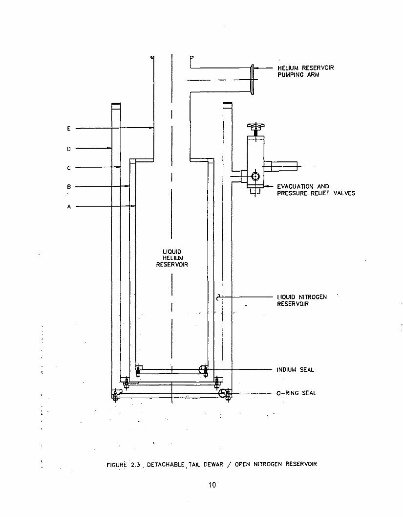
While some liquid helium and nitrogen dewars are made in anall welded design, others can be made with detachable bottomflanges for additional versatility. Figures 2.3 and 2.4show examples of such helium dewars.
In both cases, a crushed indium seal is used at the bottomof the helium reservoir and an o~ring seal at the bottom ofthe outer jacket. A radiation shield flange is mechanicallyattached to the bottom of the annular nitrogen reservoir.This arrangement offers access to the helium reservoirthrough the bottom of the dewar. It also allows varioustail extensions to be welded to these flanges to give avariety of configurations.
The two detachable tail dewars shown in figures 2.3 and 2.4have slightly different designs. The first one is an allwelded construction (except for the bottom flanges), withthe nitrogen reservoir supported at its outer tube (e) andthe helium reservoir supported off the inner tube (B) of thenitrogen reservoir. When the liquid nitrogen reservoir isfilled, the liquid is in direct contact with the top flange,and neck (E) of the helium reservoir. The nitrogenreservoir is thus completely open at the top, and usually aremoveable cover is placed to fill the gap between the neckand the outer tube (C) of this reservoir.
9
EAL
ITROGENIR
SEAL
nON ANDRE RELIEF VALYES
RESERVOIRG ARM
• FHELIUMPUMPIN-
= I =Cfi~==
I'-r:=L .,p
L ]" EVACUAPRESSU
LIQUIDHELIUM
RESERVOIR
,LIQUID N,
I .. RESERVO,.
r, , ri:INDIUM S
--t '+' 't
-ht:J't
~ O-RING"
"t' .
A
B
C
E
D
FIGURE 2,3 . DETACHABLE, TAIL DEWAR / OPEN NITROGEN RESERVOIR
10
SEAL
G SEAL
NITROGENVOIR
AllON ANDURE RELIEf
G SEAL
M RESERVOIRNG ARM
~ FHELIU
- PUMPI
,I
,
c;-: O-RIN
I 4EVACUPRESS
f-- • VALVES
I'~ I I
.'0/'-I,
LIQUIDHELIUM
RESERVOIR ,LIQUIDlRESER
II±., ..... INDIUM
h-- '+' .,fT-
_~....,'¥ ~ O-RIN-'T' 'T'
f
A
B
E
D
G
fiGURE 2.4 DETACHABLE TAIL DEWAR / CLOSED NITROGEN RESERVOIR
11
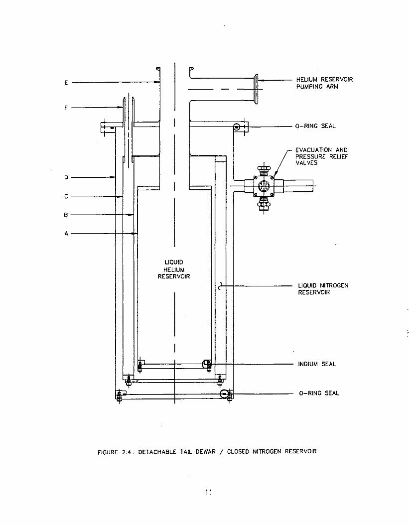
The dewar shown in figure 2.4 shows a nitrogen reservoirthat is supported by three (fill/vent) tubes (F) which arethermally isolated from the top flange. The outer (vacuum)jacket is usually completely removeable from the top flange.The helium reservoir is supported independently by its neck,off the top flange. A copper thermal anchor then links thetop of the nitrogen reservoir to the helium reservoir neck,in order to intercept the conductive heat load from roomtemperature. Both reservoirs are surrounded by vacuum, withthe only top access via the fill/vent tUbes or the neck.This dewar design is usually referred to as a closednitrogen, detachable tail dewar, and it results in a muchlower liquid nitrogen consumption rate.
C. Tail Extensions
As mentioned earlier, one of the main advantages of a. detachable tail dewar is that a tail extension can be addedto the dewar. These result in either constant or variabletemperature cryostats, that can be used for a large varietyof scientific experiments at low temperatures. A fewexamples of such tail extensions will be discussed in whatfollows.
1. Immersion Tails
The simplest extension tail that can be added to adetachable tail dewar, is one which extends the heliumreservoir directly into a narrower region (tail) below thedewar. Figure 2.5 shows such a set of tails, attached tothe bottom of a detachable tail dewar. The helium tail(diameter C) is simply an extension of the helium reservoir,with liquid helium inside it. The (aluminum) radiationshield tail (diameter B) is welded to the radiation shieldflange, which in turn is bolted to the bottom of thenitrogen reservoir, and is thus conductively cooled. Theouter tail (diameter A) is welded to the bottom O-ringsealed flange, and now becomes an extension of the outervacuum jacket. The main application of this configurationis to fit in a limited space such as the pole gap of anelectro-magnet. The usual clearance required between thehelium tail and outer tail diameters is a function of thelength L, but is normally 1" (A-C = 1"). This clearance maybe reduced to 0.5" (or less) with appropriate use ofconcentricity spacers between the tails, to avoid physicalcontact which would result in a thermal short. The additionof such spacers between the tails will result in anadditional heat load into the helium and/or nitrogenreservoir which could result in a higher cryogenconsumption. These spacers are added only when dictated bythe geometrical configuration desired.
12

~r----
1..--- r--..
LIQUIDHELIUM
RESERVOIR
:I r:-
f---, J -.tl
---Ih'" l.fJ ....I-
-
I
c L
B
A LJ..,;
FIGURE 2.5 IMMERSION TUBULAR TAIL
13

I ,....--.............-- ----/"'
JL10UIDHELIUM
RESERVOIR
n r:
- ;r ~ ...---- I
1._::--1 ~ r-:_-
~-..
A
B
I yC
WINDOWS
~
nON SHIELD I II I
PENINGS II I
-1 !J" ~WINDOWS=F"'"
~ I xE HOLDER
l
RADIAo
OUTER
SAMPL
INNER
FIGURE 2.6 IMMERSION OPTICAL'TAIL
14
\,
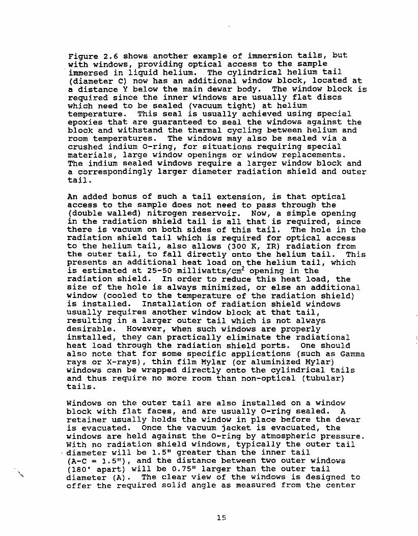
Figure 2.6 shows another example of immersion tails, butwith windows, providing optical access to the sampleimmersed in liquid helium. The cylindrical helium tail(diameter C) now has an additional window block, located ata distance Y below the main dewar body. The window block isrequired since the inner windows are usually flat discswhich need to be sealed (vacuum tight) at heliumtemperature. This seal is usually achieved using specialepoxies that are guaranteed to seal the windows against theblock and withstand the thermal cycling between helium androom temperatures. The windows may also be sealed via acrushed indium O-ring, for situations requiring specialmaterials, large window openings or window replacements.The indium sealed windows require a larger window block anda correspondingly larger diameter radiation shield and outertail.
An added bonus of such a tail extension, is that opticalaccess to the sample does not need to pass through the(double walled) nitrogen reservoir. Now, a simple openingin the radiation shield tail is all that is required, sincethere is vacuum on both sides of this tail. The hole in theradiation shield tail which is required for optical accessto the helium tail, also allows (300 K, IR) radiation fromthe outer tail, to fall directly onto the helium tail. Thispresents an additional heat load on the helium tail, whichis estimated at 25-50 milliwatts/cm2 opening in theradiation shield. In order to reduce this heat load, thesize of the hole is always minimized, or else an additionalwindow (cooled to the temperature of the radiation shield)is installed. Installation of radiation shield windowsusually requires another window block at that tail,reSUlting in a larger outer tail which is not alwaysdesirable. However, when such windows are properlyinstalled, they can practically eliminate the radiationalheat load through the radiation shield ports. One shOUldalso note that for some specific applications (such as Gammarays or X-rays), thin film Mylar (or aluminized Mylar)windows can be wrapped directly onto the cylindrical tailsand thus require no more room than non-optical (tUbular)tails.
Windows on the outer tail are also installed on a windowblock with flat faces, and are usually O-ring sealed. Aretainer usually holds the window in place before the dewaris evacuated. Once the vacuum jacket is evacuated, thewindows are held against the O-ring by atmospheric pressure.With no radiation shield windows, typically the outer tail
. diameter will be 1.5" greater than the inner tail(A-C = 1. 5"), and the distance between two outer windows(180' apart) will be 0.75" larger than the outer taildiameter (A). The clear view of the windows is designed tooffer the required solid angle as measured from the center
15

of the sample tUbe, consistent with the limitations dictatedby the cryogenic seal of the inner window. The size andmaterial type of windows used, are also a function of thetransmission range (wavelength or frequency) required. Avariety of window materials that will withstand thermalcycling between helium and room temperature are available tocover most regions of the electromagnetic spectrum. Thedimensions of the outer tail and window block can sometimesbe reduced by appropriate use of spacers between the varioustails, and by epoxying the outer windows. This latteroption reduces the distance between opposing windows sincethe o-ring and tapped holes for the window retainer will nolonger be required.
The above two examples of tail extensions are designed forapplications where the sample is immersed in the liquidcryogen. This is usually done by introducing the samplethrough the top of the dewar, using a long thin wallstainless steel tube to support it off the top of the neck.~he temperature of the liquid cryogen (~nd the sample) maythen be reduced below the normal boiling point, by reducingthe pressure on top of the liquid. Using a typical 27 cfmroughing pump can usually reduce the temperature of a heliumreservoir to below 2 K (at a pressure of 24 torr or less).
2. Tails for Sample in Vacuum
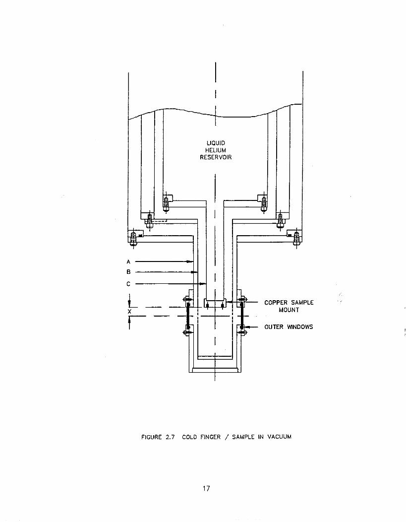
Some experiments require the sample to be cooled down whilesurrounded by vacuum. For such cases, one can locate thesample in the dewar vacuum, using a tail extension similarto the immersion tails, except that the sample is locatedbelow the bottom flange of the inner tail.
Figure 2.7 shows such a tail" extension (similar to Figure2.6), where the bottom of the helium tail is sealed by acopper flange. The face of the copper flange which lies invacuum contains some (dead) tapped holes, and is located ata distance x above the window center line. This copperpiece acts as a sample mount (usually called a cold finger)for attaching samples in vacuum. since the cold finger isin contact with the liquid cryogen (above it), it remains atthe temperature of the cryogen. Samples or sample holdersattached to the cold finger must be thermally anchored verycarefully in order to be cooled, since the cooling isprimarily achieved by contact with the cold finger (invacuum). This is usually done by using pressure contactswith either an indium interface, good conductive epoxies orsilicone grease. It is always best to install a thermometerat the sample, in order to measure its actual temperature,which may be several degrees above the temperature of thecold finger. A second radiation shield attached to the cold
16
LE
WS
I-
~- --- ---~-LIQUIDHELIUM
RESERVOIR
:I r;
~ I :-
---_;,1. "Irt-, -
"¥
A
BI
C
L ~~I
A.COPPER SAMP-- --
X I I MOUNT
t -- - ~~ : - -I I
-E r- OUTER WlNDO
I
FIGURE 2.7 COLD FINGER / SAMPLE IN VACUUM
17
finger, and surrounding the sample, is usually quite helpfulin reducing the radiational heat input into the sample.
The same configuration can be provided without outerwindows, for experiments not requiring optical access to thesample. In such a case, the diameter of the outer tail willbe about 1" larger than the diameter of the inner tail(A-C = 1"). When windows are supplied on the outer tail,the diameter of the outer tail does not change, and thewindow to window distance (for 180· opposing windows) willbe about 0.75" larger than the outer tail diameter (A).Once again, the outer tail diameter and window to windowdistance may be reduced by appropriate use of concentricityspacers and epoxied windows.
The temperature of the liquid cryogen (and the sample mount)can be varied, in the same manner as the immersion tails, byreducing the pressure on top of the liquid in the innerreservoir. A radiation shield bolted to the sample mount(surrounding the sample) is again advisable, especially atlower temperatures, in order to help reduce the temperaturedifferential between the sample and its holder.
Changing samples in such a configuration is significantlydifferent from the immersion tail configuration. Whereas inthe immersion case one can remove and introduce samples intothe cryogen any time the cryogen is at atmospheric pressure,this cannot be done when the sample is in vacuum. Now, thedewar must be free of cryogens, and preferably at roomtemperature, before the sample is removed or installed sinceone needs to break the dewar vacuum. If the dewar is stillcold, then air and moisture can condense (or freeze) on thevacuum walls of the dewar, and would need to be completelycleaned and dried prior to evacuating and re-cooling thedewar. For this reason"tooiit is "undesirable to providesuch-a tail for a dewar with MLI, since re-evacuation cantake a long time, especially if any moisture condenses onthe MLI.
18
3. VARIABLE TEMPERATURE CRYOSTATS
The simple helium (or nitrogen) dewars discussed previously,allow cooling an apparatus to the temperature of the boilingcryogen, either by direct immersion or by attachment to acold finger in contact with the cryogen. The temperaturecan be reduced below the normal boiling point of the cryogenby simply reducing the pressure on top of the cryogen. Ifthe temperature needs to be varied above that of thecryogen, then one usually needs an external heat input intothe sample holder. If the sample holder is in good thermalcontact with the liquid cryogen, then any heat added to thesample holder will quickly be transmitted into the cryogen,and ends up boiling away the cryogen without significantlyraising the temperature of the sample. ThUS, the firstrequirement for obtaining higher temperatures is the abilityto thermally isolate the sample from the cryogen. If thisis done after the sample is cooled, then any heat added to
"the sample holder will increase its temperature above thatof the cryogen, while a temperature gradient develops acrossthe isolating element. In a well designed system, littleheat is required to raise the temperature of the sample wellabove the temperature of the cryogen, without significantlyincreasing the cryogen consumption rate.
Another method of obtaining temperature variation above thenormal boiling point, is to channel a small flow of thecryogen into the sample region and vaporize the cryogen withan external heat source and raise its temperature to thedesired level. This method works very well with liquidsthat have a low heat of vaporization (e.g., helium), whilethe sample is placed ~n the path of the flowing heatedvapor. When liquids having large heats of vaporization(e.g., nitrogen) are used, it becomes difficult to vaporizethe liquid and increase its temperature. In such a case onecan either work with flowing cold vapor which can be easilyheated, or else separate the sample from the flowing liquidand then add heat to the sample.
Several kinds of variable temperature cryostats will bedescribed in what follows, falling under the generalcategories discussed above for temperature variation. Thesecryostats are designed for use with liquid helium or liquidnitrogen, since these are the two most commonly availablecryogens. These cryostats can usually be used with othercryogens (liquids air, oxygen, argon, neon, hydrogen) withcertain modifications dictated by safe handling of the gasinvolved.
19
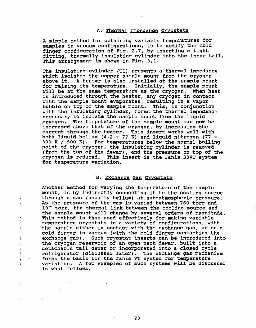
A. Thermal Impedance Cryostats
A simple method for obtaining variable temperatures forsamples in vacuum configurations, is to modify the coldfinger configuration of Fig. 2.7, by inserting a tightfitting, thermally insulating cylinder into the inner taiLThis arrangement is shown in Fig. 3.1.
The insulating cylinder (TI) presents a thermal impedancewhich isolates the copper sample mount from the cryogenabove it. A heater is also installed at the sample mountfor raising its temperature. Initially, the sample mountwill be at the same temperature as the cryogen. When heatis introduced through the heater, any cryogen in contactwith the sample mount evaporates, resulting in a vaporbubble on top of the sample mount. This, in conjunctionwith the insulating cylinder, forms the thermal impedancenecessary to isolate the sample mount from the liquidcryogen. The temperature of the sample mount can now beincreased above that of the cryogen, by increasing thecurrent through the heater. This insert works well withboth liquid helium (4.2 - 77 K) and liquid nitrogen (77 300 K / 500 K). For temperatures below the normal boilingpoint of the cryogen, the insulating cylinder is removed(from the top of the dewar), and the pressure on top of thecryogen is reduced. This insert is the Janis SSVT systemfor temperature variation.
B. Exchange Gas Cryostats
Another method for varying the temperature of the samplemount, is by indirectly connecting it .. to the cooling sourcethrough a gas (usually helium).at.sub-atmospheric pressure.As the pressure of the gas is varied between 760 torr and10.4 torr, the thermal link between the cooling source andthe sample mount will change by several orders of magnitude.This method is thus used effectively for making variabletemperature cryostats in a variety of configurations, withthe sample either in contact with the exchange gas, or on acold finger in vacuum (with the cold finger contacting theexchange gas). Such cryostat inserts can be introduced intothe cryogen reservoir of an open neck dewar, built into adetachable tail dewar or incorporated into a closed cyclerefrigerator (discussed later). The exchange gas mechanismforms the basis for the Janis VT system for temperaturevariation. A few examples of such systems will be discussedin what follows.
20

I -~.---
...,.'-/
n I r.
I--: ~ '----
_1:1 ..". ,J ,,_
- -
C I
n ~~HEATER !J-
- I
COPPER --I II
II
SAMPLE I I
MOUNT ~ ~
FIGURE 3.1 THERMAL IMPEDANCE CRYOSTAT
21
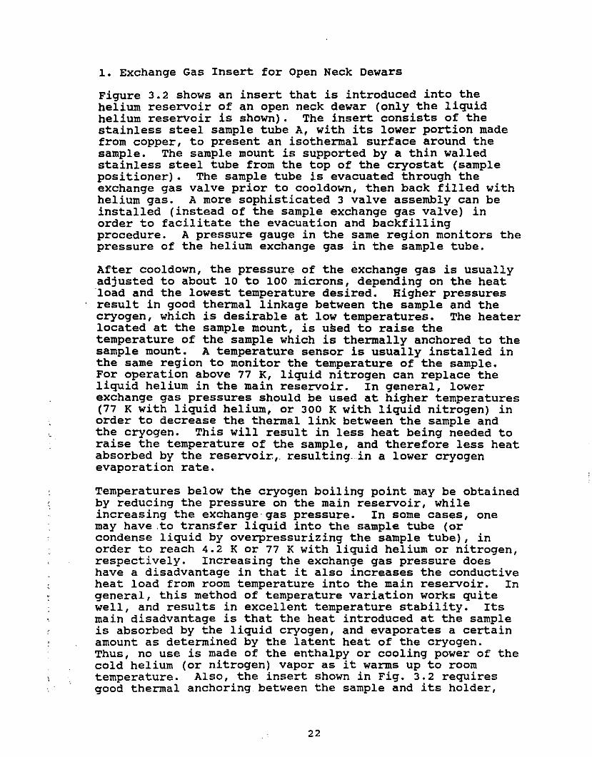
1. Exchange Gas Insert for Open Neck Dewars
Figure 3.2 shows an insert that is introduced into thehelium reservoir of an open neck dewar (only the liquidhelium reservoir is shown). The insert consists of thestainless steel sample tube A, with its lower portion madefrom copper, to present an isothermal surface around thesample. The sample mount is supported by a thin walledstainless steel tUbe from the top of the cryostat (samplepositioner). The sample tube is evacuated through theexchange gas valve prior to cooldown, then back filled withhelium gas. A more sophisticated 3 valve assembly can beinstalled (instead of the sample exchange gas valve) inorder to facilitate the evacuation and backfillingprocedure. A pressure gauge in the same region monitors thepressure of the helium exchange gas in the sample tUbe.
After cooldown, the pressure of the exchange gas is usuallyadjusted to about 10 to 100 microns, depending on the heatload and the lowest temperature desired. Higher pressuresresult in good thermal linkage between the sample and thecryogen, which is desirable at low temperatures. The heaterlocated at the sample mount, is used to raise thetemperature of the sample which is thermally anchored to thesample mount. A temperature sensor is usually installed inthe same region to monitor the temperature of the sample.For operation above 77 K, liquid nitrogen can replace theliquid helium in the main reservoir. In general, lowerexchange gas pressures should be used at higher temperatures(77 K with liquid helium, or 300 K with liquid nitrogen) inorder to decrease the thermal link between the sample andthe cryogen. This will result in less heat being needed toraise the temperature of the sample, and therefore less heatabsorbed by the reservoir,. resulting.. in a lower cryogenevaporation rate.
Temperatures below the cryogen boiling point may be obtainedby reducing the pressure on the main reservoir, whileincreasing the exchange· gas pressure. In some cases, onemay have.to transfer liquid into the sample tube (orcondense liquid by overpressurizing the sample tUbe), inorder to reach 4.2 K or 77 K with liquid helium or nitrogen,respectively. Increasing the exchange gas pressure doeshave a disadvantage in that it also increases the conductiveheat load from room temperature into the main reservoir. Ingeneral, this method of temperature variation works quitewell, and results in excellent temperature stability. Itsmain disadvantage is that the heat introduced at the sampleis absorbed by the liquid cryogen, and evaporates a certainamount as determined by the latent heat of the cryogen.Thus, no use is made of the enthalpy or cooling power of thecold helium (or nitrogen) vapor as it warms up to roomtemperature. Also, the insert shown in Fig. 3.2 requiresgood thermal anchoring between the sample and its holder,
22

EXCHANGE GAS VALVE
LIQUID HELIUM(NlffiOGEN) RESERVOIR
SAMPLE POSInONER
J
r hL. f-J
~~~
RE GAUGE .n. .~
u r ~
!to
f I ~
,l
N BAFFLES ~ -------
I
LESS STEEL)
ER)
MOUNTATER
--
SAMPLEWITH HE
PRESSU
A (STAIN
SPACER
A (COPP
RADIAno
FIGURE .3.2 EXCHANGE GAS INSERT
23

since the sample is cooled by the exchange gas, but isheated through its contact with the sample mount. A morecomplicated (two wall) insert can be set up with heatingintroduced to the lower (copper) section of the sample tUbe,in order to heat the exchange gas itself. The exchange gasthen heats both sample and sample mount. Such anarrangement eliminates the thermal interface between thesample and the sample mount, and results in easierdetermination of the sample's temperature.
The top loading design of this cryostat allows sampleinterchange while the dewar is cold. This is accomplishedby bringing the pressure in the sample tUbe up toatmospheric, then quickly removing the sample mount andcovering the top entrance of the sample tube to prevent anyair or moisture from entering it.
2. Exchange Gas Inserts for Detachable Tail Dewars
Using the same concept for isolating and connecting thesample to the cooling source, through an exchange gas in adetachable tail dewar, one obtains several usefulconfigurations of variable temperature cryostats. Two suchexamples are discussed in what follows, showingconfigurations that place the sample inside the exchange gascolumn or on a cold finger (in vacuum). Both examples showoptical access to the sample, but if no optical access isrequired, the tail insert can be simplified by eliminatingthe windows. Non-optical inserts are obviously morecompact, and the tail's dimensions can generally beoptimized for tight fitting experiments (such as fitting inthe pole gap of an electromagnet).
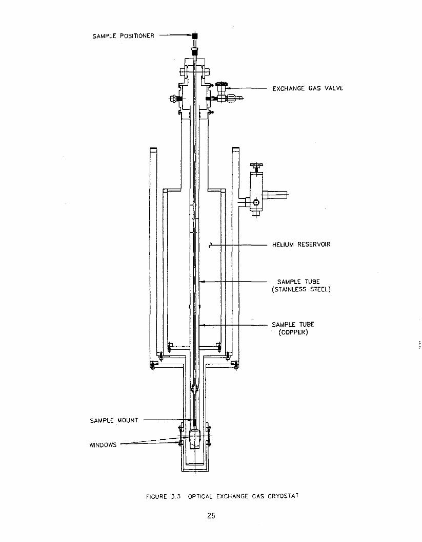
i. Sample in Exchange Gas
Figure 3.3 shows a detachable tail dewar with an exchangegas tail insert, placing the sample in contact with theexchange gas and providing optical access to the sample.The tails are attached to the bottom flanges of the dewar,with the innermost tail permanently attached to the heliumreservoir bottom flange. This tail becomes the sample tube,which extends to the top of the cryostat. It contains theexchange gas, with the sample loaded through the top of thecryostat. The lower portion of the sample tUbe is usuallymade from copper, part of which lies inside the heliumreservoir, while the\lowest part is surrounded by the dewarvacuum. This configuration maintains the lower portionclose to liquid heliUm temperature (or liquid nitrogen, innitrogen dewars), and the sample is located in this region.The upper part of the sample tube is made from stainlesssteel to reduce the conductive heat load from roomtemperature. The pressure of the exchange gas determinesthe thermal link between the sample and the cryogen, in
24
M RESERVOIR
ANGE GAS VALVE
LE TUBEPPER)
PLE TUBENLESS STEEL)
POSITIONER
~ h... f-'
iIo' ijlEXCH
~ri
c-~
'--- - iIoI--' '-
i= I :::
F= =l-r
...L.
I 't
HELIU
I SAM(STAI
SAMP(CO
Ii-, ....I-t I.-
L....... '.......
I
OUNT
.
= =
SAMPLE
SAMPLE M
WINDOWS
FIGURE 3.3 OPTICAL EXCHANGE GAS CRYOSTAT
25

AMPLE MOUNTOLD FINGER
EXCHANGE GAS VALVE
HEAT EXCHANGER
WINDOW
[ .~ il.~
,'-"
1,- f,- il&- '--
::: :::I
, I
E
.
Ih .-l
H ~
~'t't' .....
't'
• S-' C
~
EXCHANGE GAS TUB(STAINLESS STEEL)
. HELIUM RESERVOIR
FIGURE 3.4 SAMPLE IN VACUUM EXCHANGE GAS CRYOSTAT
26

exactly the same manner as the previous cryostat insert.The innermost tail is surrounded by a radiation shield andan outer tail with windows, in the same manner as theimmersion tail units (Fig. 2.6). Installation of radiationshield windows will reduce the heat load on the sample tUbe,and thus reduce the helium consumption and the lowesttemperature that can be reached at the sample. The samplecan also be immersed in liquid helium if the liquid istransferred directly into the sample tube or condensed byoverpressurizing helium gas in the sample tube. The latteroption boils off a significant amount of helium from themain reservoir since the warm helium gas is cooled andcondensed by dumping this energy into the liquid helium inthe main reservoir.
ii. Sample in Vacuum
Figure 3.4 shows a set of insert tails which provides a coldfinger for attaching a sample in (the dewar) vacuum. Thecold finger is isolated from the helium reservoir by a thinwall stainless steel tUbe, which also acts as the exchangegas space. The exchange gas inside this tube forms the(variable) thermal link between the cryogen and the coldfinger. A (copper) heat exchanger is connected to the coldfinger to increase the link between the exchange gas and thecold finger, and thus increase the cooling power at thelowest temperature. A heater, located at the cold finger,is used to raise and control the temperature of a sampleattached to the sample mount.
Exchange gas cryostats work quite well with either liquidhelium or liquid nitrogen dewars. In a helium dewar, thehelium reservoir may·be filled with liquid nitrogen whenevertemperatures above liquid nitrogen are required. Helium gasis usually used as the exchange gas with either liquidhelium or liquid nitrogen, because of its high thermalconductivity, but one could use nitrogen gas when liquidnitrogen is used as the cryogen in the main reservoir.
c. Continuous Flow cryostats
As discussed above, temperature variation can be obtained bychanneling a small flow of cryogen continuously to thesample region, and controlling its temperature. The cryogenmay be contained in the main reservoir of the dewar (such asthe Janis superVaritemp cryostats), or could be continuouslytransferred from a storage dewar (such as the JanisSuperTran cryostats). Since the cryogen has to be vaporizedbefore raising its temperature, these cryostats are usuallydesigned to operate with liquid helium. This is especiallythe case when the sample is located in the flowing vapor.In some instances the same cryostat may also be used withliquid nitrogen, with or without minor modifications.
27
Several examples of such cryostats will be discussed in whatfollows.
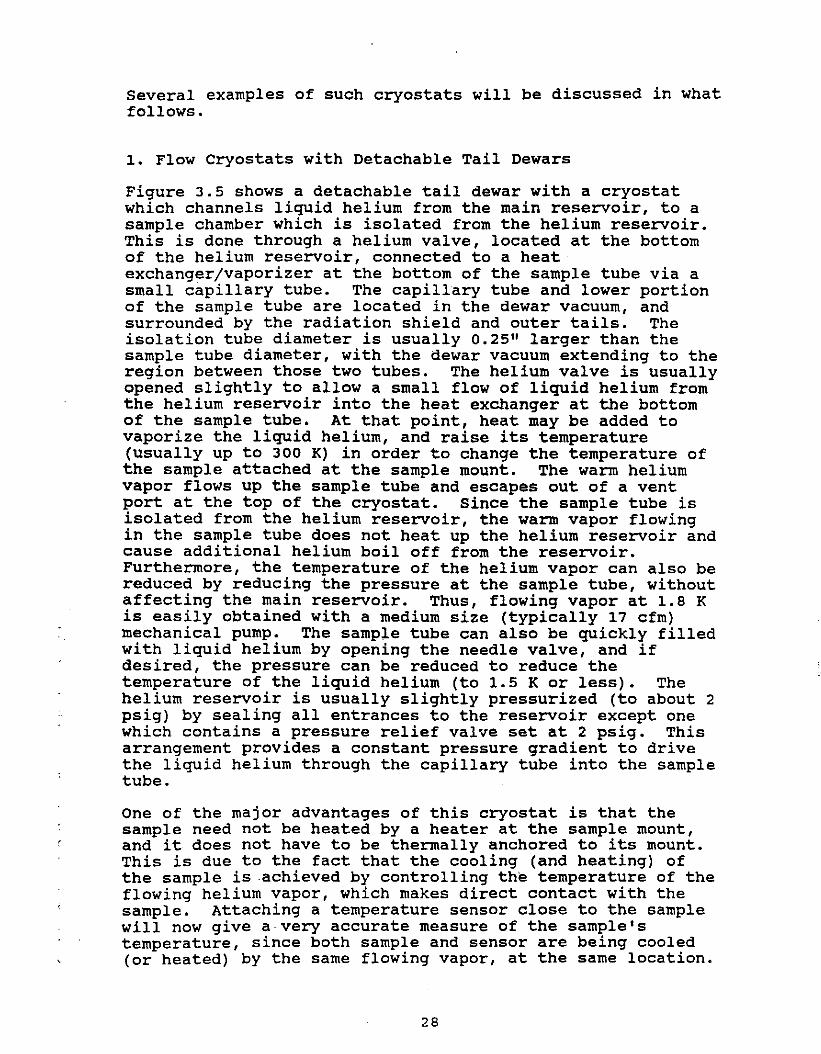
1. Flow Cryostats with Detachable Tail Dewars
Figure 3.5 shows a detachable tail dewar with a cryostatwhich channels liquid helium from the main reservoir, to asample chamber which is isolated from the helium reservoir.This is done through a helium valve, located at the bottomof the helium reservoir, connected to a heatexchanger/vaporizer at the bottom of the sample tUbe via asmall capillary tube. The capillary tUbe and lower portionof the sample tUbe are located in the dewar vacuum, andsurrounded by the radiation shield and outer tails. Theisolation tube diameter is usually 0.25" larger than thesample tube diameter, with the dewar vacuum extending to theregion between those two tUbes. The helium valve is usuallyopened slightly to allow a small flow of liquid helium fromthe helium reservoir into the heat exchanger at the bottomof the sample tube. At that point, heat may be added tovaporize the liquid helium, and raise its temperature(usually up to 300 K) in order to change the temperature ofthe sample attached at the sample mount. The warm heliumvapor flows up the sample tUbe and escapes out of a ventport at the top of the cryostat. Since the sample tUbe isisolated from the helium reservoir, the warm vapor flowingin the sample tube does not heat up the helium reservoir andcause additional helium boil off from the reservoir.Furthermore, the temperature of the helium vapor can also bereduced by reducing the pressure at the sample tube, withoutaffecting the main reservoir. Thus, flowing vapor at 1.8 Kis easily obtained with a medium size (typically 17 cfm)mechanical pump. The sample tube can also be quickly filledwith liquid helium by opening the needle valve, and ifdesired, the pressure can be reduced to reduce thetemperature of the liquid helium (to 1.5 K or less). Thehelium reservoir is usually slightly pressurized (to about 2psig) by sealing all entrances to the reservoir except onewhich contains a pressure relief valve set at 2 psig. Thisarrangement provides a constant pressure gradient to drivethe liquid helium through the capillary tube into the sampletube.
One of the major advantages of this cryostat is that thesample need not be heated by a heater at the sample mount,and it does not have to be thermally anchored to its mount.This is due to the fact that the cooling (and heating) ofthe sample is achieved by controlling the temperature of theflowing helium vapor, which makes direct contact with thesample. Attaching a temperature sensor close to the samplewill now give avery accurate measure of the sample'stemperature, since both sample and sensor are being cooled(or heated) by the same flowing vapor, at the same location.
28

LATION TUBE
OIAnON SHIELO
MPLE POSITIONER
TER TAIL
PORI ZER / HEATCHANGER
MPLE TUBE
L1UM RESERVOIR
MPLE TUtiE VENT
SA
f -a
i -~ SA
~
III Cji ~F
<= i:=
=r:~~
HE
ISO
ISA
Eii .b!i l.-
I p~
OU
RANT
l-~BE
VAEX
HELIUM VALVEOPERATOR
HELIUM VALV
SAMPLE MOU
CAPILLARY TU
FIGURE 3.5 FLOW CRYOSTAT WITH DETACHABLE TAIL DEWAR
29
Thus one usually installs a control sensor at the vaporizer,and a second sensor at the sample mount for precisemeasurement of the sample's temperature. such anarrangement is quite easily handled by most commerciallyavailable automatic temperature controllers. A typicaltemperature sweep between 4.2 K and room temperature takesabout 30 to 45 minutes, as long as the mass of the heatexchanger remains reasonable small.
Another advantage of this system is that operation below4.2 K is done without have to reduce the pressure on themain reservoir, which usually evaporates about 40% of theliquid helium by the time it is cooled to 2 K. this isparticularly important if a superconducting magnet islocated in the helium reservoir. Furthermore, throttlingthe valve and reducing the pressure in the sample tUbe,results in a stream of 1.8 K helium flowing past the sample.This mode presents the least amount of interference inoptical experiments where the presence of superfluid (ornormal) helium cannot be tolerated.
This variable temperature system is the basis for the JanisSuperVaritemp cryostat with sample in flowing helium vapor.optical access to the sample is provided by adding outer andinner windows to the tail region, with the finalconfiguration resembling the tail region of Fig. 3.3. Thissystem is also capable of dissipating large amounts of heatthat may be generated at the sample (due to laser beams orother sources), since the helium valve and pressure gradientcan be adjusted to provide a large flow (a few liters ofliquid helium/hr) into the sample tUbe.
The sample holder is top loaded into the sample tube and itsposition adjusted by the sample positioner at the top of thecryostat. A simple 0.25" tube passing through an a-ringcompression seal allows rotation as well as translation ofthe sample mount about the dewar axis. Above 4.2 K, withthe pressure in the sample tUbe at 1 atmosphere, changingsamples is simple, since the flow of helium (coming inthrough the bottom of the sample tUbe) prevents air fromeasily entering the sample chamber.
By modifying .the design of the heat exchanger (vaporizer) inthis insert one can also provide two useful configurations.The first one offers bottom optical access by making atoroidal vaporizer, and ·adding windows at the bottom of theouter and radiation shield tails. One slight disadvantageof this arrangement is that the inner bottom window tends toget dirty from any foreign material that enters the sampletube, and settles at the bottom. The other modification ofthe heat exchanger is to machine it with a flat mountingsurface (with dead tapped holes) so that it acts as a coldfinger for attaching samples in vacuum. The capillary tubecan now enter through the side (as opposed to the bottom) of
30

the heat exchanger, into the venting tube (what used to bethe sample tUbe) in order not to interfere with samplemounting surface of the cold finger. The sample is locatedin the dewar vacuum, and can only be replaced by breakingthe dewar vacuum, with the dewar at room temperature.
The temperature stability (at the sample) in the rangebetween 4.2 K and 25 K is usually better than ±0.1 K, usingan appropriate automatic temperature controller. Thestability is inherently limited due to the two phase mixture(liquid and vapor) of helium flowing past the sample.Should a better stability be required, a simple exchange gasinsert, with a bottom isothermal section (made from copper)can be inserted through the top of the cryostat, inside thesample tube. This insert now becomes the new sample tUbe,and results in a much better temperature stability at thesample. Such an insert is also very useful for equipmentthat may be disturbed by any gas flowing across the sample,such as Faraday Balance experiments. With the samplelocated in a static exchange gas, any disturbance due toflowing helium vapor is now eliminated.
Whereas the design of the vaporizer allows vaporization of areasonable flow (100 to 500 cc/hr) of liquid helium enteringthe sample tUbe, attempting to do this with liquid nitrogenis usually unsuccessful. This is due to the relativelylarge heat of vaporization of liquid nitrogen. A modifiedinsert can be made which draws nitrogen vapor from theullage space on top of the liquid nitrogen, then channel itthrough the vaporizer. Such an insert must allow theflowing nitrogen to be cooled to a reasonable temperature(80-85 K) before it enters the sample tUbe. An externalsource of heat may also be required in order to develop andmaintain a small over-pressure, in._order to. maintain areasonable flow of cold vapor into the sample tube. Thistype of an insert is the basis for the Janis NSVT variabletemperature system, which places the sample in a flowingnitrogen vapor.
2. Flow Cryostat Inserts for Open Neck Dewars
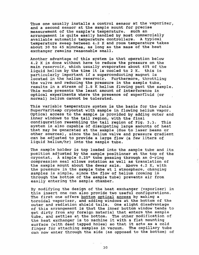
Using the concept for the cryostat described above (C-1), avariable temperature cryostat insert can be made for usewith open neck research or storage dewars. Such a cryostatwould have its own independent vacuum jacket to isolate thesample tube from the main reservoir, and a helium valve todraw the liquid into the sample tube in a controlled manner.Such inserts are very useful for introduction into the boreof a superconducting magnet located in a research dewar(Fig. 3.6). The magnet has its own support structure, andthe insert can be removed without disturbing the magnet.
31
INSERT EVACUAllONVALVE
SAMPLE VENT TUBE
HELIUM RESERVOIR
SUPERCONDUCTINGSOLENOID
SIllONER
r "-L
I~.J4l'
VE!to Jg.. ~
~~
IE;:+: j:T L..;+.j=tI
I
- -I.-
,BAFFLES .-/-L-
V, --
PPORT
IBE ,
I J"
TUBE
LVE
0= I b:
LIe-
F=l~
1\ i
1\//I¢: ,
\ a~ \!=!=
VAPORIZER
SAMPLE TU
MAGNET SU
RAOIAllON
ISOLATION
HELIUM VA
INDIUM SEA
BORE TUBE
SAMPLE PO
HELIUM VALOPERATOR
FIGURE 3.6 FLOW CRYOSTAT INSERT FOR SUPERCONOUCTING MAGNET

The insert itself may also be used to support the magnet andeliminate the independent magnet support. The insert'sisolation (bore) tube diameter is determined by the magnet,with the sample tube's diameter approximately 0.5" smallerthan the isolation tube. The space between the sample andisolation tubes is evacuated, and the capillary tubecarrying the helium from the main reservoir into the samplechamber lies in that vacuum space.
Access to the capillary tube and vaporizer (with itsassociated heater and control sensor) is through ademountable indium (or solder) seal. The helium reservoirshould be pressurized (with a simple pressure relief valve)in order to maintain the slight over-pressure needed todrive the helium through the needle valve, capillary tUbe,and heat exchanger into the sample tube. The mostconvenient place for such a valve is at the (common) exhaustof any vapor cooled high current magnet leads, since thismaintains the necessary flow of cold helium vapor throughthe leads.
Temperature variation is done in precisely the same manneras the detachable tail insert cryostat, and covers the rangeof about 1.8 K to 300 K in flowing vapor, or down to 1.5 Kin superfluid helium. Once again, operation below 4.2 K isachieved without pumping on the main reservoir whichcontains the superconducting coil.
3. Continuous Transfer cryostats
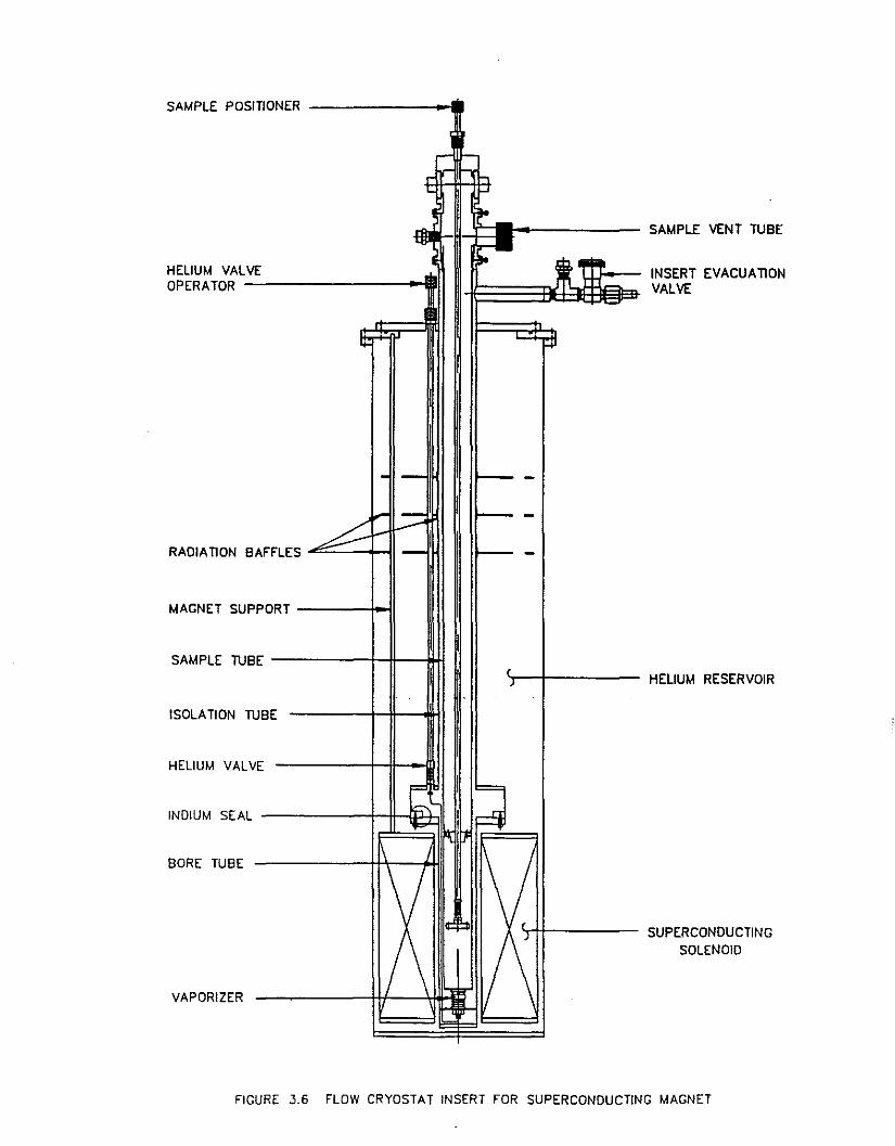
In many cases it is preferable to eliminate the researchdewar with its own helium (and/or nitrogen) reservoir,because of lack of space or a desire for a more portable.cryostat. For such applications, an efficient vacuuminsulated transfer line, with a flexible section, can beused to carry the cryogen from a storage dewar to a smallcryostat. Figure 3.7 shows an example of such a transferline, with a flow control valve located at the bottom of thestorage dewar leg. This arrangement is preferable to an "inline" valve since it presents a lower heat input into theflowing cryogen.
The outer line has a flexible section (5-10 ft. long) toprovide more maneuverability, while the inner line may bemade from 1/16" or 1/8" stainless steel tubing and issurrounded by MLI. Properly designed and located spacerskeep the inner line concentric within the outer flexibleline. The storage dewar leg is usually made to matchtypical storage dewars, with a 1/2" diameter and a 40-60"length. The entire line is vacuum insulated with anevacuation valve available for maintaining a good vacuum(10"5 torr), plus a safety pressure relief valve to guardagainst cold internal leaks. With careful design and
FLEXIBLE SECllON
HELIUM VALVE OPERATOR
INSULATEDCRYOSTAT
LEG
EVACUAllON
VALVE
STORAGE DEWAR LEG ------------1
HELIUM VALVE
FIGURE 3.7 FLEXIBLE TRANSFER LINE FOR CONTINUOUS TRANSFER
, 34

manufacturing techniques, the heat load on the inner linecan be reduced to less than 400 milliwatts for a typicalunit (6 ft. flexible section, 1/16" inner line, 48" storagedewar leg and 20" cryostat leg). This line can be used tocontinuously transfer the cryogen into the cryostat, so itis important to have it as efficient as possible.
Two types of configurations are used with this transferline. One unit provides a cold finger with the sample invacuum, while the other unit places the sample in the pathof flowing vapor. These two configurations are describedbelow.
i. Sample in Vacuum
Figure 3.8 shows a simple cold finger cryostat that mateswith the transfer line shown in Fig. 3.7. The leg of thetransfer line fits inside an O-ring compression seal at thetop of the cryostat, and delivers the cryogen to the insideof the cold finger. The cryogen exits through a concentricstainless steel tUbe (isolation tUbe) and cools a thermalanchor to which a radiation shield is attached. The cryogeneventually exits at a vent port away from the detachableseal for the vacuum jacket.
The outer (vacuum) jacket is usually sealed by a quickremovable elastomer seal to allow easy access to the sampleholder. The radiation shield, which is cooled by theescaping vapor, may be bolted to the thermal anchor, and isrequired for use with liquid helium. The cryostat can alsobe used with liquid nitrogen, as long as the flow controlvalve can be adjusted to significantly reduce the flow. Aheater located at the cold finger will allow temperaturevariation above 4.2 K (liquid helium) or 77 K (liquidnitrogen). Optical access to the sample is easily achievedby adding windows to the vacuum jacket, and holes (orwindows) to the radiation shield. Evacuation and pressurerelief valves, as well as vacuum tight electricalfeedthroughs are usually located above the joint of theremoveable vacuum jacket, in order to provide the necessaryvacuum and wiring access to the cold finger.
Although such cryostats may be operated in any orientation,the vertical position requires the least amount of cryogenat any specific temperature. Temperatures above 4.2 K canbe obtained by reducing the liquid helium flow, or by addingheat at the cold finger wound heater. Temperatures below4.2 K are obtained by either throttling the flow controlvalve and pumping at the vent port, or by allowing helium tocollect on top of the cold finger and reducing the pressure(at the vent port) with the flow valve closed. The lattermode usually results in the lower temperature (approximately1.8 K). This system forms the basis for the JanisSuperTran-B cryostat.
35

TRANSFER LINE ENTRANCE
IO-RING COMPRESSION SEAl
VENT PORT
EVACUAllON VALVE
DETACHABLEELASTOMER SEAL -----olI'OrJ
ELECTRICALFEEDTHROUGH
THERMAL ANCHOR
VACUUM JACKET
RADIAllDN SHIELD
ISOLAllON TUBE
COLD FINGERSAMPLE MOUNT
FIGURE 3.B CONTINOUS TRANSFER COLD FINGER CRYOSTAT
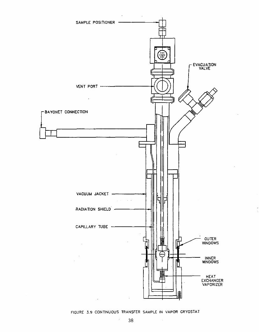
ii. Sample in Vapor
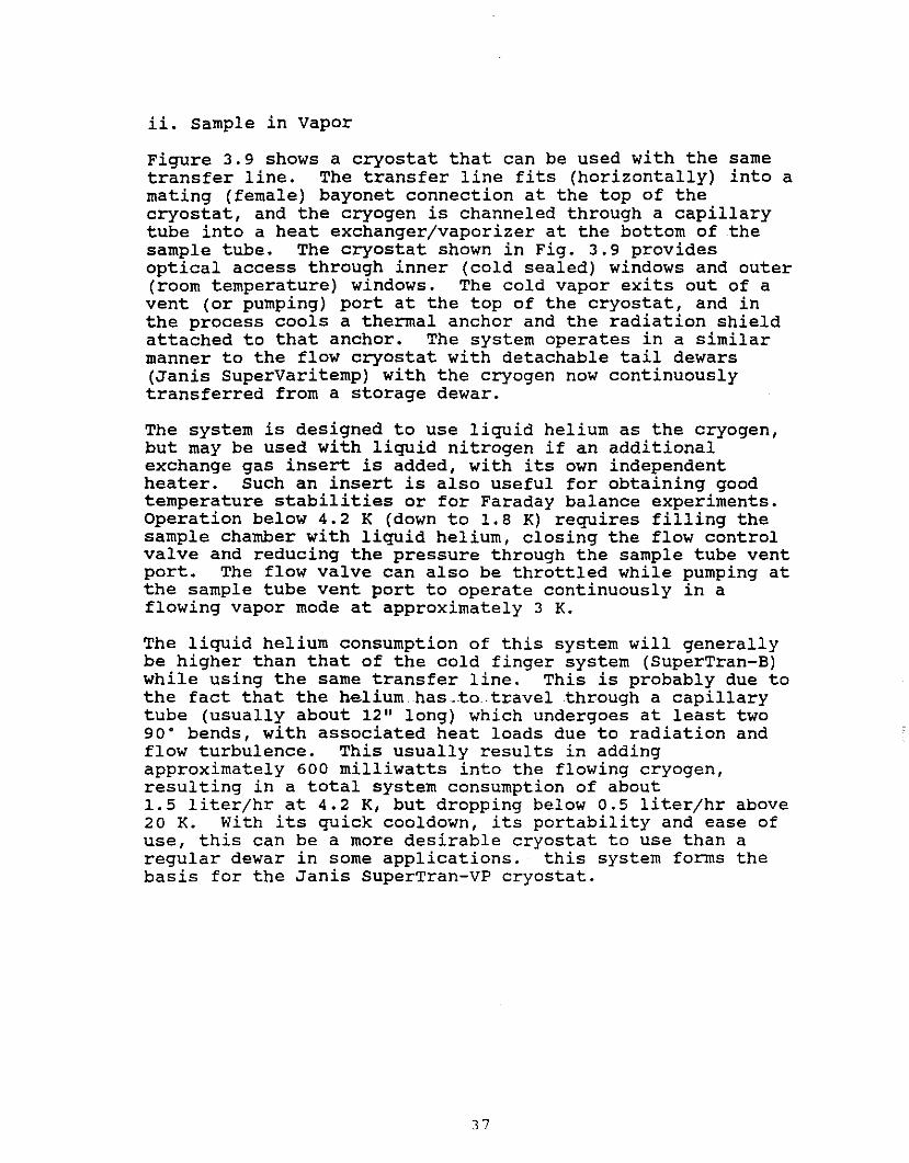
Figure 3.9 shows a cryostat that can be used with the sametransfer line. The transfer line fits (horizontally) into amating (female) bayonet connection at the top of thecryostat, and the cryogen is channeled through a capillarytube into a heat exchanger/vaporizer at the bottom of thesample tUbe. The cryostat shown in Fig. 3.9 providesoptical access through inner (cold sealed) windows and outer(room temperature) windows. The cold vapor exits out of avent (or pumping) port at the top of the cryostat, and inthe process cools a thermal anchor and the radiation shieldattached to that anchor. The system operates in a similarmanner to the flow cryostat with detachable tail dewars(Janis SuperVaritemp) with the cryogen now continuouslytransferred from a storage dewar.
The system is designed to use liquid helium as the cryogen,but may be used with liquid nitrogen if an additionalexchange gas insert is added, with its own independentheater. Such an insert is also useful for obtaining goodtemperature stabilities or for Faraday balance experiments.Operation below 4.2 K (down to 1.8 K) requires filling thesample chamber with liquid helium, closing the flow controlvalve and reducing the pressure through the sample tUbe ventport. The flow valve can also be throttled while pumping atthe sample tube vent port to operate continuously in aflowing vapor mode at approximately 3 K.
The liquid helium consumption of this system will generallybe higher than that of the cold finger system (SuperTran-B)while using the same transfer line. This is probably due tothe fact that the heliumhas_.to. travel .through a capillarytube (usually about 12" long) which undergoes at least two90· bends, with associated heat loads due to radiation andflow turbulence. This usually results in addingapproximately 600 milliwatts into the flowing cryogen,resulting in a total system consumption of about1.5 liter/hr at 4.2 K, but dropping below 0.5 liter/hr above20 K. With its quick cooldown, its portability and ease ofuse, this can be a more desirable cryostat to use than aregular dewar in some applications. this system forms thebasis for the Janis SuperTran-vP cryostat.
37
SAMPLE POSITIONER
@... .••
EVACUA~ONVALVE
VENT PORT --------~
BAYONET CONNEC~ON
VACUUM JACKET
RADIA~ON SHIELD
CAPILLARY TUBE
OUTERWINDOWS
INNERWINDOWS
HEATEXCHANGERVAPORIZER
FIGURE 3.9 CON~NUOUS TRANSFER SAMPLE IN VAPOR CRYOSTAT
38

4. SUPERCONDUCTING MAGNET SYSTEMS
The improvement in the manufacturing and productiontechniques of superconducting wires and coils within thepast twenty years (as of 1990), has made them readilyavailable to most research laboratories. The most commonmaterials that are commercially available forsuperconducting magnets are the type II superconductors NbTiand NbSn, with the latter having the higher critical field.Since these materials lose their superconductive propertiesabove a certain critical temperature (along with anassociated critical field and current density), the magnetswound from these materials are usually immersed in liquidhelium during operation. For this purpose, a variety ofliquid helium research dewars and cryostats have beendesigned to contain these magnets and offer temperaturevariation with optical and/or physical access to the highfield region. An example of one such cryostat was shown inFig. 3.6, where the magnet was supported from the topflange, and an independent variable temperature insertproviding temperature variation in the high field region.The magnet support system contains radiation baffles (asdoes the variable temperature insert) to prevent roomtemperature radiation from reaching the liquid heliumthrough the top of the reservoir. The baffles are cooled bythe helium vapor boiling out of the main reservoir, and theyalso force the vapor to interact more intimately with theneck of the helium reservoir. This further reduces theconductive heat load down the neck, as was mentionedearlier.
For magnetic fields of 5-9 Tesla (at 4.2 K), twistedmultifilament NbTi (embedded_in__ copper) wires are used toeliminate flux jumping and associated heat generation.Typically these magnets run at currents that range between50 and 100 Amperes for laboratory magnets (up to about 4"bore). These same magnets may also reach fields of up to 11or 12 Tesla when operated at pumped helium temperatures(2.2 K), where the values of the critical current andmagnetic field are larger. Nb3Sn magnets are used for thehigher fields (12 to 17 Tesla), but these magnets tend to besignificantly more expensive. with such (relatively) largecurrents, special vapor cooled leads are usually used in theneck region, with a good portion of the escaping heliumvapor forced to pass through these leads. This flow reducesthe temperature, the resistance, and the Joule heatinggenerated due to the large current passing through theseleads. In addition, the helium vapor also intercepts theconductive heat load coming from room temperature down theleads. The bottom of the vapor cooled leads is alwayslocated above the liquid helium level to allow free flow ofhelium vapor through them. The vapor cooled leads are thenconnected (either permanently or through a detachable joint)
39
to low resistivity copper and superconducting cables whichrun to the magnet at the bottom of the helium reservoir.Detachable joints are used when one wants the option ofeliminating the conductive heat load down the magnet leads,when there is no electric current passing through the leads.
In many instances it is desirable to run a superconductingmagnet in a closed (superconducting) loop. This is donethrough a persistent current switch, which consists of asmall length of superconducting wire shorting the magnetterminals, with a small heater wire wrapped around it. Theheater is capable of raising the temperature of the switch,and thus forcing it into its normal (resistive) state. Thisenables the power supply to send current through the(superconducting) magnet for charging it up to the ratedfield (or any lower field). At that point the persistentswitch heater may be turned off to place the magnet in thepersistent mode, while the current in the leads which comesfrom the power supply to the magnet may be reduced to zero.
-This eliminates any Joule heating in the leads and leaves avery stable current (and magnetic field) in the magnet.Typical decay rates of commercially available magnets areabout 10 to 25 ppm/hr. When the field needs to be changed,the power supply can be turned back on, in order to reestablish the same current through the leads, and finallythe persistent switch heater is turned back on. The powersupply now regains control of the magnet, and the necessarychanges in the current can be made. The persistent switchheater usually generates about 150 milliwatts which resultsin an additional helium boil-off of 210 cc/hr.
Magnet power supplies are usually provided with a sweepgenerator to charge the magnet at various rates, and havespecial protection (usually diodes) to protect againstvoltage mismatch with the-magnet as may be encountered whenthe magnet is switched out of its persistent mode, or if themagnet should accidentally turn "normal" and discharge.Some power supplies are also designed with an energyabsorbing circuit which allows relatively quick dischargesfor magnets with large inductance.
In addition to the high current leads for the magnet, thetop flange should also contain an electrical feedthrough forwiring the persistent switch heater and voltage taps thatrun directly to the coil terminals in the helium reservoir.The voltage taps are used to monitor the precise voltageacross the magnet, required to charge the magnet at aspecific rate. This is determined by the relation.
E = LeUdt
,
where E is the applied voltage at the magnet, L theinductance of the coil and dI/dt the rate of change of the
40

current passing through the coil. The inductance and thecharging voltage are usually specified for each individualcoil, resulting in a maximum charging rate which should notbe exceeded, since it may result in generating too much heatin the coil, which can force it into its normal (resistive)state. This would result in a magnet quench, where all themagnetic stored energy (1/2 LI2) will dissipate as Jouleheating in the magnet, and absorbed by the liquid heliumaround the magnet. Other causes of magnet quench would beoperating the magnet above its rated current, or allowingthe liquid helium level to drop below the magnet, to a levelwhich warms the magnet above its critical temperature. Aliquid helium level sensor should always be installed in thehelium reservoir to monitor the level of the liquid helium,and make sure it remains at a safe level.
Typical laboratory magnets have inductances of 10 to 20Henries and operate at maximum currents of 50 to 100Amperes. The stored energy for these magnets thus rangesbetween a few thousand to a 100 thousand Joules, which wouldneed to be dissipated very rapidly (few seconds) in case ofa magnet quench. The magnets are thus designed to absorbthis energy, and the dewar should have a quench relief portto vent the large amount of helium gas which is generated asthe magnet dumps this heat into the liquid helium reservoir.The magnet should have protective diodes across itsterminals (or a protective resistor circuit) to protect itduring such a quench. The higher field magnets (12 to 17Tesla) are usually made in a hybrid design, where two ormore sections are connected in series (NbTi in the lowerfield outer region and Nb3sn in the high field innerregion), and each section would have its own protectivecircuit. In addition, since the quench can result in verylarge generated voltages at the windings, special devicesare used to reduce the voltage surges within the windings.
The magnet design also takes into account the forces thatare generated at the windings when the magnet is at fullfield. In straight solenoids, these forces generally resultin added tension along the windings which can easily supportthe stress. In magnets with "bucking" coils (to reduce thefield at a specified location near the center of the magnet)or gradient coils, the structure is designed to support therepUlsive forces between the coils, so no wire movement(Which may result in a magnet quench) occurs. In split orHelmholtz coils that are required for optical access orradial access to the high field region, the former (orbobbin) holding the coils should also be designed towithstand the attractive force between the two sections,without allowing any significant deflection. Thus, a welldesigned system should always consider the magnet andcryostat as one unit to suit specific experiments, alongwith any required automatic control for the temperature,magnetic field or physical measurement in question.
41
The cryostat should always allow access from the top flangeto the bottom of the helium reservoir (below the magnet),either directly or through an initial helium fill line.This allows liquid nitrogen pre-cool, (and removal of allthe nitrogen from the helium reservoir) and also allowsdelivering the liquid helium to the lowest point in thehelium reservoir during initial helium t~ansfer. This isvery critical since it allows full use of the cooling powerof the helium vapor to cool the magnet down from 77 K to4.2 K. with the helium transfer starting at a slow steadyrate, which does not allow liquid helium accumulation beforethe magnet cools down to 4.2 K, the cooldown usuallyrequires 0.4 liters per kilogram of magnet. A much fasterhelium transfer could fill the helium reservoir quickly,only to result in a very high evaporation rate which canempty the helium reservoir in the next 30 minutes as themagnet gets cooled using only the low heat of vaporization
. of liquid helium. Installing a thermometer at the magnet,or monitoring the resistance of the coil as it is beingcooled, are helpful for inexperienced users. Any heliumrefills should deliver the new liquid at a level higher thanthe level of the existing liquid (above the magnet), inorder not to risk evaporating any of the existing liquid (byinserting a warm transfer line leg or initially delivering amixture of.warm gas and liquid). A few examples of typicalsuperconducting magnet cryostat systems will be described inwhat follows.
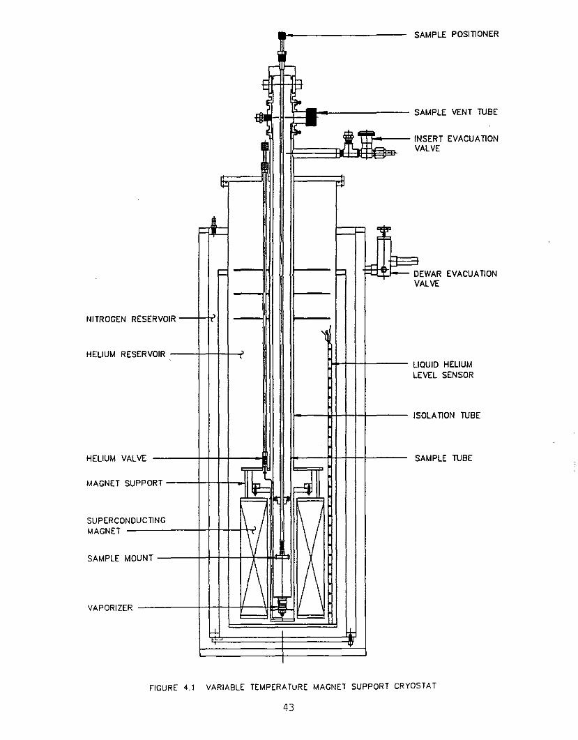
A. Variable Temperature Top Loading systems
Figure 4.1 shows an open neck liquid· nitrogen shielded,liquid helium research dewar with a variable temperatureinsert which supports a superconducting solenoid at itsbottom. The insert draws' helium from the main (dewar)reservoir, and channels it to the sample tube through thevaporizer at the bottom of the sample tube. This is thesame flow cryostat design described earlier, where theflowing helium vapor can be controlled in temperaturebetween 1.8 and 300 K. The evacuated isolation tUbeencloses the sample tube, and prevents the warm helium vaportravelling up the sample tube from heating up the helium inthe main reservoir. It also allows operation below 4.2 K,by simply pumping at the sample tube (as described insection 3).
This cryostat is very similar to the one shown in Fig. 3.6,except that the magnet is now supported from the bottom ofthe insert, thus eliminating the need for an independentmagnet support. A helium level sensor monitors the level tomake sure it covers the magnet during operation. Vaporcooled high current leads are usually used withcopper/superconducting cables to carry the current to the
42
OLAnON TUBE
AMPLE TUBE
EWAR EVACUAnONALVE
aUlD HELIUMEVEL SENSOR
NSERT EVACUAnONVALVE
SAMPLE VENT TUBE
SAMPLE POSITIONER
r ~
~ -'
.... ~..,.,to
H~ ~ I
IIi' :jJ
iii It"'"
"II!'
I k-~ 1= D
V
RESERVOIR.
'I
ESERVOIR ,LIL
IIS
IALVE S
• =!
UPPORT~ ~
DUCnNG \/ I 1\/rOUNT
R1\ ,~ 1/\
~~i-l. +-
VAPORIZE
SAMPLE M
SUPERCONMAGNET
NITROGEN
HElIUM R
MAGNET S
HElIUM V
FIGURE 4.1 VARIABLE TEMPERATuRE MAGNET SUPPORT CRYOSTAT
43
coil. The magnet may also have a persistent current switchand some thermometer to monitor its cooldown. The diameterof the helium reservoir should be large enough to allow atransfer line leg to fit between the magnet and the wall ofthe helium reservoir. This allows efficient cooldown from77 K and also allows easy removal of liquid nitrogen fromthe helium reservoir after cooldown from room temperature.
The top flange should contain helium fill and vent portsplus a quench relief port (in case of accidental magnetquench), along with an electrical feedthrough to wire thelevel sensor, magnet voltage taps and any persistent switchheater or magnet thermometer included in the system. Thevapor cooled leads should have their exhaust joined into asingle chamber with a pressure relief valve set atapproximately 1 psig. This will allow the helium to ventthrough the leads, while maintaining the necessary pressuredifferential to drive liquid helium through the needle valve
_and capillary tube into the sample tube.
If the magnet is designed to offer a higher magnetic fieldat 2.2 K, it is convenient to add a Lambda plate between thehelium valve of the variable temperature insert and the topof the magnet. Such a refrigerator will have its own heliumvalve and pumping line, which allows it to cool the liquidhelium below its location, to 2.2 K. In such a case it isuseful to have a field independent thermometer (such as acarbon glass resistor) installed at the magnet to monitorits temperature during operation of the Lambda plate. Whenthe magnet reaches 2.2 K, the current through it can then beincreased to its higher value in order to provide a higherfield. The liquid helium in the upper section of thereservoir stays at atmospheric pressure, and regUlar heliumtransfer and operation of ~he variable temperature cryostatis maintained.
B. optical Access Straight Solenoid Systems
When optical access is required into the high field regionof a variable temperature cryostat, the easiest way is touse a detachable tail dewar with a bottom window and astraight solenoid. An example of such a cryostat is shownin Figure 4.2, with the sample mount removed. The heatexchanger (vaporizer) at the bottom of the sample tube has atoroidal shape with a window at its center for bottomoptical access into the sample tUbe. Helium is channeledfrom the main reservoir through a capillary tUbe and needlevalve, controlled from the top of the dewar. In many casesa detachable joint is made at the bottom of the vapor cooledleads in order to reduce the conductive heat load into thehelium reservoir, when no current is passing through theseleads. Again as in the previous variable temperatureinserts, the sample tUbe is separated from the helium
44

SAMPLE ENTRY
SAMPLE VENT TUBE
EVACUATlON VALVE
VAPOR COOLED LEADS_m
NITROGEN RESERVOIR --++--~,
MOUNTING FLANGE -
NITROGEN RADIATIONSHIELD
..
,•
1\/ I 1\//\ /\
I d:HELIUM VALVE...
f+, ...I-VAPORIZER
4, ... .,.. ... ..+...
t...
OPTICAL ACCESS
MAGNET ------+-++--+1--',
HELIUM RESERVOIR
FIGURE 4.2 MAGNET CRYOSTAT WITH BOTTOM OPTICAL ACCESS
45
reservoir by a vacuum (in the isolation tube), in order tomaintain low helium consumption as the temperature increasesto room temperature. This configuration forms the basis forthe Janis optiMag System.
A simpler exchange gas insert may also be used for thisconfiguration (as well as the configuration described inSection 4.5). Such an exchange gas insert would provide asample tube (in direct contact with the liquid helium) whichfits directly into the bore of the magnet. The sample wouldbe mounted on a copper sample mount in the exchange gas,with a heater for raising its temperature. For a givenmagnet bore, this offers a slightly (0.25") larger samplespace than the previous insert since no isolation tubesurrounds the sample tube. Since the magnet must always beimmersed in liquid helium (NbTi or Nb3sn coils), one has toreduce the exchange gas pressure for operation attemperature above 77 K, in order to maintain a low
·consumption of liquid helium. Furthermore, the sampleshould be in very good contact with the sample mount sinceit is heated indirectly through the sample mount heater.Finally, operation below 4.2 K requires pumping on theentire helium reservoir (containing the magnet), or theinclusion of a Lambda plate.
c. optical Access Split Solenoid Systems
Experiments requiring optical access along two or threedirections into the high field region of a variabletemperature cryostat, are best done with a split orHelmholtz type coil. The variable temperature cryostatprovides horizontal windows (looking through a vacuum) intothe sample tube as is -shown--in Fig. 4.3. optical accessalong the vertical direction can also be supplied (as in 4.5above) if desired. The magnetic field direction can beeither horizontal or vertical, with the horizontalconfiguration slightly preferable since light can then bedirected either along or perpendicular to the magneticfield. Once again helium is channeled through a needlevalve and capillary tube into the vaporizer at the bottom ofthe sample tube. The sample tube is surrounded by vacuuminside the isolation tube, which is connected to the vacuumbobbin on which the split coil is wound. An initial heliumfill adapter sends a tube to the bottom of the heliumreservoir for efficient cooldown of the magnet from 77 K to4.2 K, and for removal of liquid nitrogen from the heliumreservoir after cooldown from room temperature to 77 K.This adapter mates with an initial transfer line guide tUbewhich is removed after the helium transfer to reduce theheat load into the helium reservoir.
46

SAMPLE VENT TUBE
SAMPLE TUBE
MAGNET
ISOLAllON TUBE
WINDOWS
INIllAL HELIUM FILL
~
- L
~I... I "'-"0
11JJI f-
. 1- 1 •'-4- ,-l-
If-
IRVOIR
I
= =
OIR I
I ~
-" mJ l'ltiI "l X X ' I'"
----iI ... X IX ...
l'
-,~ T
"t1 It"
HELIUM RESERV
NITROGEN RESE
HELIUM VALVE
FIGURE 4.3 MAGNET CRYOSTAT FOR MAGNETO-OPTICAL EXPERIMENTS
47

Radiation shield windows are usually installed in order toreduce or eliminate the radiational heat load to the heliumreservoir from the large openings in the radiation shield.These openings are usually I" to 2" in diameter to maintaina large solid angle for the scattered or incident beams.The sample is top loaded into the sample tube, and is cooled(or heated) by the helium vapor whose temperature is .controlled at the vaporizer. The sample holder (not shownin Fig. 4.3) can be attached on a simple 0.25" diameterstainless steel tube passing through an O-ring compressionseal at the top flange. such an arrangement allows easyrotation and/or translation of the sample along the axis ofthe sample tube. The helium vapor exits out of a port atthe top of the sample tUbe, and temperatures below 4.2 K areattained by reducing the pressure in the sample tube whilethe sample tUbe is filled with liquid helium, or while theneedle valve is throttled (as in 3.B). This system gives anoperating temperature range from below 2 K up to roomtemperature, and is the basis of the Janis SuperOptiMag
- cryostats.
The windows at the sample tube may be strain relief mountedfor experiments requiring polarized light. Since the sampletube and window block has to fit between the two split coils(in the radial ports), this usually requires a largerseparation between the coils. In general this leads to abigger magnet and a larger helium reservoir for the samesize sample chamber.
D. Magnet Systems for Special Applications
Many applications require a large m~gnetic field forexperiments conducted at room temperature. In such cases asuperconducting coil is installed in a helium dewar with aroom temperature bore tube, surrounded by one or tworadiation shield bore tUbes, which in turn is surrounded bythe helium bore tube through the bore of the superconductingsolenoid. The magnetic field may be either in a vertical orhorizontal direction, with the dewar designed accordingly.The simplest configuration is the vertical room temperaturebore in an open neck dewar which allows the magnet to be toploaded into the dewar. Since the outermost bore tube inthese dewars runs directly from room temperature into thehelium reservoir, this usually results in a higher liquidhelium boil-off rate. A more efficient design, which offersa vertical room temperature bore, contains the magnet insidea sealed helium reservoir where the helium bore tUbe iswelded to the top and bottom flanges of the heliumreservoir. The dewar is then more difficult to assemble andthe magnet is trapped inside the helium reservoir.
Closed cycle refrigerators can be incorporated into thedesign of magnet dewars with room temperature bores. In
48

such cases, the helium reservoir is surrounded by tworadiation shields which are cooled by the two stages of therefrigerator. Detachable vapor cooled leads are built intothese dewars in order to disconnect the leads after themagnet is charged, and allowed to operate in the persistentcurrent mode. This generally reduces the helium evaporationrate anywhere from 5 cc/hr to 50 cc/hr depending on the sizeof the dewar and the refrigeration capacity of the closedcycle refrigerator used. This arrangement is only used whenthe application requires extended operation (about 30 days)in a constant magnetic field.
other specialized applications require very low temperatures(0.3 K) in a magnetic field. A compact self contained He3insert is usually used for these applications, designedeither to fit directly into the helium reservoir containingthe magnet, or into an existing variable temperature insert.Since He3 inserts require a pumped He4 bath to condense the~He3 gas, such an insert will contain its own He4 bath orelse make use of the helium bath offered by the variabletemperature insert. This eliminates the necessity forreducing the pressure on the helium reservoir containing themagnet. A charcoal pump built into these inserts offers aconvenient method of reaching 0.3 K at the He3 bath withoutthe complication of a special gas handling system for theexpensive He3• A cold finger arrangement is the mostdesirable one since it requires no handling of the He3 whichmight contaminate it. Access to the He3 cold finger isthrough a room temperature, a-ring sealed joint or through asmall indium sealed joint (in the variable temperatureinsert).
49

5. CLOSED CYCLE REFRIGERATOR SYSTEMS
Where handling of liquid nitrogen and liquid helium is notdesired or when obtaining these liquids is difficult, amechanical (closed cycle) refrigerator can be used to cooldown the samples. The most common (commercially available)refrigerators make use of a two-stage Gifford-McMahon cycleusing high purity (99.999%) helium gas as the working fluid.In these units, the cold head is separated from thecompressor by a couple of flexible high pressure tubes whichcarry the compressed helium into and out of the cold head.This enables easy handling of the cold head which weighsabout 8 kg, while the heavy (approximately 65 kg) compressoris stationed in a fixed location nearby (about 3 m). Thecold head contains the displacers (pistons) that are used topush the gas and change the volume it occupies inside thetwo stages, and also the regenerators (reverse flow heat
.exchangers). These regenerators are placed inside thedisplacers and are usually packed with materials that have apoor thermal conductivity, high specific heat, and a largesurface area to enable them to absorb the heat from theincoming warm helium gas, and give up heat to the colderexiting helium gas.
A typical (Gifford-McMahon) cycle may be described in termsof four steps that are periodically repeated.
1. The inlet valve to the high pressure (250-300 psi)helium gas line from the compressor is opened, withthe displacers in their upper positions (offering asmall volume inside the cold head).
2. The displacers _.are._pushed down, expanding the volumesin the cold head, and drawing more helium gas from thehigh pressure line. This gas passes through theregenerators, giving up some of its heat to the coolerregenerators.
3. The inlet valve to the high pressure line is closed,and the exhaust valve to the low pressure (100 psi)line is opened. This causes the helium gas to cool asit expands into the low pressure discharge line. Thisprocess provides the cooling to the two stages of therefrigerator (and any load attached to them), and alsohelps cool the regenerators.
4. The displacer is pushed back up, driving the coldhelium gas through the exhaust valve into the lowpressure line to the compressor. As this exiting gasgives up its heat to the regenerator, it is warmed toa temperature slightly less than room temperature andless than the incoming helium gas temperature. Italso leaves the regenerators at a lowered temperature,
50
which enables them to pre-cool the incoming gas at thebeginning of the next cycle.
The high and low pressure valves are usually actuated by arotary mechanism in the cold head, which is driven by anelectric synchronous motor. The displacers may either bepneumatically activated by a control piston, driven byalternating low and high pressure, or by the electric motoritself. The frequency of the displacer movement is about 2to 3 HZ, and varies with the frequency of the available acsignal (usually 50 or 60 Hz). The lower frequency (50 Hz)results in a lower refrigeration capacity for a specificrefrigerator. The motor and associated piston (displacer)movement in the cold head, results in a certain level ofvibration being transmitted to the cold finger and outerbody of the cold head. Fortunately, these vibrations arequite tolerable for most experiments at low temperatures.Special vibration isolation techniques must however be usedfor some critical experiments (such as MossbauerSpectroscopy), typically using flexible copper braids, orpreferably an exchange gas mechanism coupled with rigidsample mounting.
The smallest available refrigerators in this class offerabout 2 watts refrigeration capacity at 20 K, and reach atemperature of 10 K (or lower) at the second stage. Thiscooling capacity is quite satisfactory for a majority ofexperiments that are conducted in a typical low temperaturelaboratory. These units also require very littlemaintenance to either the cold head or compressor.Typically one needs to replace a filter (activated charcoaladsorber) in the compressor every 9,000-10,000 hours of use.This filter removes all traces of oil vapors from the heliumgas returning to the cold head, and if not replaced couldresult in some oil vapors contaminating the cold head andfreezing there. In some systems, replacement of thedisplacers and associated gasket seals is also recommendedafter this period of operation. An elapsed-time meter atthe compressor keeps track of the total operating time.
The compressor also contains a heat exchanger, which is usedto dissipate the heat generated when the helium gas iscompressed. Both water cooled and air cooled systems areavailable, with the air cooled one usually slightly moreexpensive. Safety protection switches are installed at thecompressor to turn it off if the temperature gets too high.This could be due to too high water temperatures, or too lowa throughput of cooling water, or too high an ambienttemperature. other protective switches turn the compressoroff if the pressure is too high or too low, and a safetypressure relief valve protects against system overcharge.The compressor and cold head must be cleaned (using 99.999%pure helium gas), and the system re-charged if it gets
51

contaminated (with air, water vapor or oil), or if thepressure drops too low (usually below 30 psi).
The construction of the cold head lends itself naturally toa cryostat with a cold finger configuration. Indeed theserefrigerators are also used (with appropriate baffles andcondensing fin arrays) as cryopumps in vacuum chambersrequiring clean environments. When used as variabletemperature cryostats, two general categories are obtained,with the sample in vacuum, or sample in an exchange gascolumn cooled by the two stages of the refrigerator. Thesetwo categories are described in what follows.
A. Cold Finger Cryostats
Figure 5.1 shows the cold head of a closed cyclerefrigerator with mechanically driven pistons, to which is
. attached a vacuum jacket and adapter, containing electricalfeedthroughs and an evacuation valve and a pressure reliefvalve (not shown).
The vacuum jacket surrounds the cold head, consisting of thesecond stage of the refrigerator which acts as a coldfinger/sample mount, and the first stage to which isattached a radiation shield surrounding the cold finger.This arrangement provides a temperature of 10 K or less (toapprox. 8 K) at the cold finger, while the radiation shieldis cooled to 60-80 K by direct contact with the first stage.The Figure shows the cold finger pointing upwards, but thecold head will operate in any orientation. A heater woundat the cold finger will allow temperature variation up toroom temperature. Should higher temperatures be required, aspecial insulating stage_can .. be..added at the second stage.This is required since the displacers inside the cold headare usually not designed to withstand temperatures muchhigher than room temperature. In this case, it is advisableto have a protection circuit to prevent the second stagefrom reaching these higher temperatures, and causing damageto the displacers.
The configuration shown in Figure 5.1 includes a simplearrangement providing optical access to the sample mount.These windows can be eliminated when no optical access isrequired, and the radiation shield and vacuum jacket can bemachined closer to the cold finger if a more compactconfiguration is needed. For very tight spaces, the coldfinger can be extended, using a long thin OFHC copperextension to the cold finger. The radiation shield andvacuum jacket can then also be narrowed down to fit insidenarrow spaces (such as a pole gap of an electro-magnet).The lowest temperature attained at the end of such a samplemount may be one (or more) degree higher than the
52
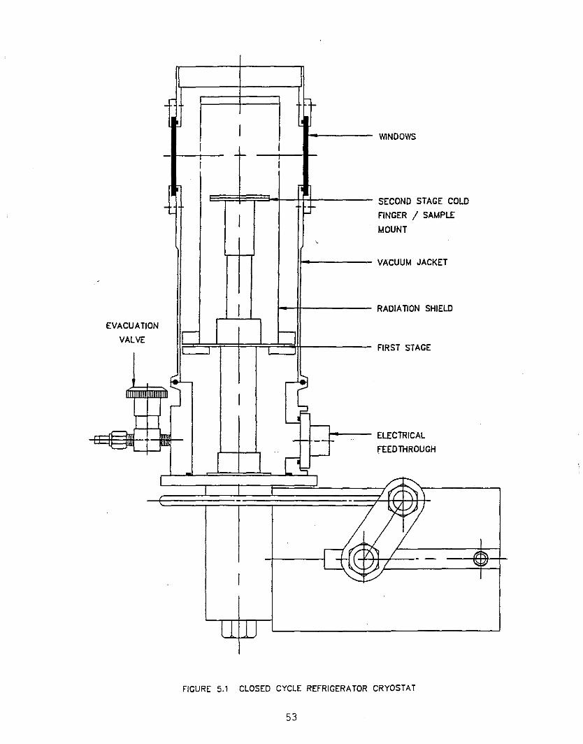
- ~
I WINDOWSI -- I
i I
- - SECOND STAGE COLD
I FlNGER / SAMPLE
MOUNT,
VACUUM JACKET
-
I RADIATlON SHIELD
EVACUATIONr-- ~
VALVEFIRST STAGE
, '- ~
IF
~ I--
~-t - '- -- .. ELECTRICAL
['::0I-- FEEDTHRDUGH
I I
~"r- YI--,'l\
~ l~1/~
~~[7\'l / __ ~ ~
L.:J ~/ \\: 11
I -,.-
I j
FIGURE 5.1 CLOSED CYCLE REFRIGERATOR CRYOSTAT
53
temperature of the cold finger, depending on the details ofthe set-up in question.
A typical system will reach its lowest temperature in aboutone hour. This will be affected by the size of the sampleholder and sample that are attached to the cold finger.Some units exhibit a small (0.1 - 0.5 K) temperaturefluctuation at the lowest temperatures achieved by the coldfinger. This is related to the displacer motion (andassociated thermodynamic cooling cycle) inside the secondstage, and may be eliminated by using an automatictemperature controller and thermometer to control thetemperature slightly higher than the lowest attainedtemperature. It can also be minimized by attaching a thin(3-5 rom thick) lead disk to the cold finger. The largerheat capacity of this new cold finger arrangement willdampen the temperature fluctuations.
As with any other cold finger (sample in vacuum) cryostat,one should not assume that the sample is exactly at the sametemperature as the cold finger. For this purpose it may beuseful to attach a thermometer to the sample, in order toobtain a more accurate measurement of the temperature of thesample.
B. Exchange Gas Cryostats
Figure 5.2 shows the cold head of a closed cyclerefrigerator, with pneumatically driven displacers, attachedto an exchange gas sample chamber surrounded by a radiationshield and vacuum jacket. The lower portion of the sampletUbe is formed from an isothermal copper surface that iscooled by direct contact'with the 'second stage of therefrigerator. The radiation shield is made from aluminum orcopper, and is cooled by direct contact with the firststage. It surrounds the main length of the sample tUbe, andis anchored to a point at the upper portion of the sampletube, to intercept the conductive heat load coming down thesample tUbe from room temperature.
The sample is attached on a copper sample mount, which issupported by a long thin walled stainless steel tUbe withbaffles, which emerges at the top of the cryostat.Electrical access to the sample area is located at the topof the sample positioner, while electrical access to thesecond stage (inside the vacuum jacket) is located near thebottom of the vacuum jacket. Heaters and controlthermometers may be attached to the second stage of therefrigerator and/or to the sample mount. The temperaturemay be controlled at either of these two points, withcontrol at the second stage being a little slower because ofthe large mass attached to that stage. with about half anatmosphere of helium exchange gas in the sample tube, the

STAGE
AllON VALVE
M JACKET
TlON SHIELD
LE MOUNT
o STAGE
LE POSITIONER
llON BAFFLES
LE TUBE
ANGE GAS VALVE
- SAMP
I-E
/EXCH
.J ~~ ~
'( -
== =
~It VACUUC:
RADIA,
SAMP
RADIA
SAMP
SECON
I
f=
lit ~It: ~
FIRST
.r f-:= -F-tl~I-,
- ... l EVACU
~ ~
-
,
..., ...,
ELECTRICAL
FEED THROUGH'S
FIGURE 5.2 EXCHANGE GAS REFRIGERATOR CRYOSTAT
55
sample and its holder can be cooled and/or heated indirectlythrough the second stage (and its heater). controlling thetemperature at the sample mount is quicker because of itssmaller mass, but it requires good thermal anchoring of thesample to the sample mount, to ensure that the sample is atthe same temperature as its mount, especially when it isheated.
The pressure inside the exchange gas tube is not as criticalas in the case of a liquid helium dewar, where one has toworry about the helium consumption. A temperature of about11.5 to 12 K is easily achieved at the sample in a properlydesigned system. This arrangement is desirable since itpermits quick sample interchange (through this top-loadingconfiguration), without having to heat up the entire coldhead and breaking its vacuum, as would be required in thecold finger configuration. One only needs to bring theexchange pressure up to atmospheric pressure, in order to
'prevent air from entering the sample tube while changingsamples. The penalty one pays for this arrangement is thehigher ultimate temperature (about 3 to 5 K higher), and theadded cost of the exchange gas system.
Another advantage of this configuration is that one candecouple the sample holder from the vibrations generated bythe drive mechanism for the displacers and valves inside thecold head. This is done by adding a vibration isolationbellows and a support flange between the sample positionerand the top of the sample tUbe. The flange can be rigidlybolted to a stationary stage which supports the sample rodand the bellows. The sample rod and holder, along with theradiation baffles should make no contact with the walls ofthe sample tUbe, and should be supported vertically from thestationary stage.
6. EXPERIMENTAL TECHNIQUES AND DATA
The final configuration for a variable temperature cryostat,will generally involve appropriate thermometry, automatictemperature control, sample attachment and system cooldown.What follows will concentrate on commercially availableinstrumentation, and general considerations for ensuringefficient cooldown and the necessary anchoring techniques toachieve the desired temperature at the sample.
1. Cooldown of Helium Cryostats and Samples
The enthalpy (total heat) of the common materials used forconstructing cryostats (stainless steel, copper,aluminum ••. ) drops rapidly with decreasing temperature.This, coupled with the low cost of liquid nitrogen and itshigh heat of vaporization (relative to helium), makes it thenatural choice to cool the dewar from room temperature downto 77 K. Once this is done, the liquid nitrogen can beremoved (from the helium reservoir) by inserting a tubewhich reaches the bottom of the reservoir, and blowing thenitrogen out through this tube by over pressurizing thereservoir. As mentioned earlier, it is very important toremove all liquid nitrogen from the helium reservoir priorto transferring liquid helium, since the heat capacity ofsolid nitrogen is quite large (an order of magnitude greaterthan for copper). Even a couple of inches of liquidnitrogen remaining in the bottom of the helium reservoir,will require large amounts of liquid helium to cool them to4.2 K and allow helium to accummulate. In simplereservoirs, the cooldown to 77 K will take less than anhour. If, however, there.is.a .. large ..mass .. (e.g • .4 Kradiation shield, or large sample) attached to thereservoir, this process may take several hours, and is bestmonitored by a thermometer attached at the end of this mass.
Once all the liquid nitrogen is removed, liquid helium canbe transferred using an appropriate helium transfer line.The vacuum jacket of the transfer line should beperiodically evacuated, and the insulated storage dewar legshould extend practically to the bottom of the storagedewar. The delivery end can be either fUlly inSUlated, orhave a short extension tip (few inches), and should deliverthe helium to the lowest point in the helium reservoir. Thehelium transfer must start at a very low rate, and bemaintained at that rate until the entire contents of thehelium reservoir (inclUding any attached mass) is cooledbelow 20 K. This ensures that one is making full use of theenthalpy of the cold helium gas, as it rises and escapes outof the top of the cryostat, to copl the reservoir and itscontents. A poor helium transfer, which does not make fulluse of this enthalpy, can use 10 times more liquid to cool
57
the dewar from 77 to 4.2 K. A poor (fast) helium transfercan also result in quick filling of the helium reservoir,even while most of the reservoir itself is at a temperatureabove 20 K. However, this usually results in the liquidhelium quickly boiling off within the next hour, as it coolsthe rest of the reservoir to 4.2 K.
Any sample being cooled, should preferably be cooled at thesame time as the helium reservoir. When the sample islocated inside the reservoir, it gets cooled (along with thereservoir) by direct contact with the helium vapor. Ifhowever, the sample is on a cold finger in vacuum, it shouldbe thermally anchored extremely well to the cold finger.This will produce faster cooldown times, and a lowerultimate temperature at the sample. If possible, athermometer should be placed at the sample (or its holder)to get a better idea of the actual temperature of thesample. This thermometer would be in addition to any.existing thermometer at the cold finger itself.
When two pieces are in contact (in vacuum) a thermal(boundary) resistance will always develop across the surfaceinterface. This usually results in a temperature differencebetween the two pieces, especially if one is cooled bycontact with a cryogen (or a cooling gas), while the otheris only being cooled through the surface contact with thefirst piece. The temperature difference which develops, isproportional to the thermal resistance and to the heat loadon the second piece. The thermal resistance can bedecreased by increasing the contact pressure between the twopieces, and by employing conductive epoxies or greases. Insome applications, a thin layer of indium is used toincrease the surface contact.
The thermal resistance between two components pressedtogether is usually difficult to measure, since it dependson the condition of the surfaces in contact. In general,the surfaces should be very clean and polished, if possible.Typical values for boundary resistances of copper to coppersurfaces with a load of 100 lbs. are about 100 K/watt at4.2 K, and 3 K/watt at 77 K. Equivalent resistances forstainless steel are 185 K/watt at 4.2 K and 3.8 K/watt at77 K. Gold plating copper surfaces can decrease theirboundary resistance by 20 times at 4.2 K (see Ref.l,Ch. VII).
When a sample is attached on a cold finger, it is necessaryto establish good thermal contact between the two, and alsoreduce the heat load into the sample as much as possible.Thus, any wires running to the sample, should be wrappedaround the cold finger and thermally anchored to it (using aconductive epoxy), prior to reaching the sample. Theradiational heat load on the sample can also be reduced bysurrounding it with a radiation shield that is anchored
58

directly to the cold finger. All these precautions aretaken to ensure that the temperature difference between thesample and the cold finger are minimized.
2. Thermometry and Temperature Control
There are many types of commercially available temperaturesensors that can be used at low temperatures. The ones thatare most commonly used are silicon diodes, germaniumresistors, carbon glass resistors, platinum resistors,Gallium (and Gallium-Aluminum) Arsenide diodes, and rhodiumiron resistors. These thermometers tend to retain theircharacteristics with repeated thermal cycling, and thus canbe reliably calibrated. Silicon, gallium arsenide andgallium-aluminum arsenide diodes are usually activated witha constant current source, and the voltages developed vary(in a reproducible manner) with temperature. Platinum and~hodium-iron resistors are also activated with a constantcurrent source and their resistance varies with temperature.Germanium and carbon-glass resistors must be activated witha variable current source since their resistances vary overseveral orders of magnitude as the temperature changes.Thermocouples consisting of a pair of dissimilar metalwires, soldered or welded together are also useful when asmall sensor is required. They generate an emf which varieswith temperature and is thus used as a basis for measuringthe temperature. In general, they are not as sensitive asother available sensors at 4.2 K (typical sensitivity for agold-iron vs. chromel thermocouple is 10 microvolt/ K), andsmall differences in the wire composition can causesignificant deviations from the standard curves. Thediscussion will thus be limited to the diode and resistancethermometers listed above.
Thermometer Installation
Before discussing the various types of cryogenicthermometers, it is important to note one commoncharacteristic of most such sensors. Even thoughmanufacturers make every effort to establish a good thermallink between the body of the thermometer and the internaltemperature sensing element, 70 to 80% of the actualtemperature sensing is through the electrical leads. Whilethis does not present any difficulties if the thermometer isin liquid helium or flowing vapor (where both the leads andthe body are immersed in the vapor), it can be a source oferror when the thermometer is attached to a cold finger invacuum. The leads running dowh from room temperature to thecold end of a helium cryostat, in vacuum, can easily carryenough heat to result in a thermometer reading of 10 K abovethe real temperature of the surface to which it is attached.It is thus extremely important to remove any "Teflonspaghetti" covering the sensor leads as they exit from the
59
body, and wrap them tightly around the cold finger andthermally anchor them with a loaded epoxy (such as Stycast2850). This of course has to be done with no electricalshorts between the leads and the cold finger.
The leads going up to room temperature should preferably bemanganin or phosphor bronze -- i.e. some alloy of lowthermal conductivity. TYPically, 32 gauge wires should beused, and they should be spiralled as they travel to theroom temperature end in order to increase their effectivelength and reduce the amount of heat they carry to the coldend. It is also important to anchor these leads to anintermediate cold stage (at 80 K), in order to intercept thelarge heat load from room temperature. A quick calculation(using the tables at the end of this chapter) may be helpfUlto ensure that the cryostat has enough cooling power tohandle the heat load due to these leads. This becomes muchmore important below 4.2 K, where the heat capacities are
'very small, and a small heat load can easily result in arelatively large rise in temperature, or erroneoustemperature reading.
Silicon Diodes
Silicon diodes have become the most common type ofthermometers used in the temperature range of 1.5 K to 300 K(or 475 K). When activated with a 10 micro-ampere constantcurrent source, they offer a voltage of about 1.7 volts atlow temperatures, dropping down to about 0.5 volts at roomtemperature. Their sensitivity ranges between approximately25 mV/ K below 20 K to 2.3 mV/ K above 70 K. Because theyare activated with a constant current, they are the obviouschoice for use with an automatic temperature controller.Their main disadvantage 'is that-their voltage changessignificantly in a magnetic field, below 77 K, and thus theycannot be used for temperature measurement or control evenwith a low magnetic field of 1 Tesla.
These thermometers are usually provided in a four wireconfiguration, which eliminates the effect of the potentialdrop across the wire leads connected to the sensor. Whenthese leads are thin copper wire (32 gauge/0.008" diam.),the potential drop along a ten foot length, with a 10microamp current source is negligible compared to the sensorvoltage -- so a two wire arrangement will be quitesUfficient. Even if 32 gauge phosphor bronze wires are used(resistance of 1 ohm/ft), the potential drop for a 10 ftlength wire will still be about 1000 times smaller than thesensor voltage.
One major advantage of silicon diode sensors is that theyare usually available imbedded in a small (about 0.3" diam.)copper disk with its leads anchored to that disk. Thisconfiguration allows quick connection of the sensor to a
60
cold finger surface (in vacuum), by simply bolting thesensor with a 4-40 screw. No other careful anchoring of theleads is required.
Finally, the silicon diodes are now mass producedcommercially, with temperature characteristics that deviateno more than 1 K (below 100 K) from a "standard" curve.This curve is usually stored on a PROM in the temperaturecontroller, which can then be used with any of these diodes.If better accuracy is needed, the diode can be calibrated,and its calibration stored in the controller.
Gallium Arsenide Diodes
GaAs and GaAIAs diodes are also excited with a constantcurrent (10 or 100 micro-Amps), but they cannot be massproduced with temperature characteristics which conform withany standard curve. They can still be calibrated and usedwith a simple (constant current) temperature controller.Their only advantage over si diodes, is that they can beused in low magnetic fields (1 to 2 Tesla) since theirvoltage does not vary significantly with the applied field.
Platinum Resistors
Platinum resistance thermometers are generally used between60 K and 300 K, where the resistance increases at a fairlyconstant rate of about 0.4 ohms/ K. They are occasionallyused down to about 20 K, but their sensitivity drops toabout 0.08 ohm/ K. Their ceramic outer case, allows thesesensors to be used up to 600·C, however it is difficult toobtain an epoxy that will thermally anchor the thermometerand its leads at the lower temperatures, and also withstandthe higher temperatures.
Platinum thermometers are usually activated with a constantcurrent, and the typical 100 ohm (at O·C) sensor will followa standard curve down to 60 K to within a couple of -degrees.Those thermometers are also useful (above 60 K) in largemagnetic fields (14 Tesla or higher) due to their smallfield induced change in resistance.
Rhodium-Iron Resistors
These thermometers offer a monotonically increasingresistance with temperature, with a typical sensitivity of0.17 ohm/ K (between 100 K and 300 K), dropping down toabout 0.08 ohm/ K at about 25 K. They are activated with aconstant current source, and may be used between 1.5 K and300 K (or up to 800 K). Their resistance varies linearlywith temperature between 100 K and 300 K, and they willfollow a standard curve to within a couple of degrees inthis temperature range. They are useful in small magneticfields (1 Tesla or less) since the typical change in
61
resistance at 4.2 K in a 1 Tesla field is equivalent toabout 0.08 K.
Germanium Resistors
These thermometers are always supplied in a four leadconfiguration, labeled for current and voltage.Installation of these sensors requires careful thermalanchoring of these leads as discussed earlier. Theresistance of these thermometers decreases with increasingtemperature, up to 100 K, where the curve starts slowlyturning -- thus limiting the usefulness of these sensors to100 K or less. One class of sensors is commerciallyavailable for use between 1.5 K and 100 K, while anotherclass is used for lower temperature ranges (6 K to 0.3 K or0.05 K). Their resistance changes by several orders ofmagnitude, thus requiring a variable current source. Whenmeasured properly at the appropriate current, and withcurrent reversal to eliminate thermal emf's, they can be avery precise thermometer because of their excellentreproducibility. Special temperature controllers have beendeveloped for these thermometers, which provide the variableexcitation current necessary for these sensors, and theytend to be a little more expensive than the equivalentcontrollers for si diodes or platinum resistors. Theresistance of these sensors varies significantly with anyapplied magnetic field, and thus they cannot be used asthermometers in such applications.
Carbon Glass Resistors
These thermometers are primarily used in high magneticfields due to the small change in resistance with appliedfield. They are supplied 'in a'four'lead configuration,similar to the Ge resistors, and they also require carefulanchoring of the leads for accurate temperature measurement.Their good temperature reproducibility and the fact thatthey have a small (orientation independent) magnetoresistance, has made them the best choice of thermometry inany magnetic field. SrTiOz capacitor sensors exhibit asmaller (relative) magnetic field dependence, but theysuffer from poor reproducibility with temperature cycling.
A typical 1000 ohm (nominal resistance at 4.2 K) carbonglass resistance thermometer will have a resistance of25,000 to 40,000 ohms at 2 K and a resistance of about6 ohms at room temperature. This wide range of resistancevariation requires a variable current source for obtainingtemperature measurements with reasonable accuracy. Theresistance increases monotonically with decrease intemperature, and the sensitivity also increases from about0.08 ohm/ K at 300 K, to about 1000 ohms/ K at 4.2 K. As inthe case of Ge resistance thermometers, there arecommercially available automatic temperature controllers,
62
with variable excitation current (from 0.1 micro Amp to1 milli Amp), that operate with carbon glass thermometers.In some instances, these controllers cannot control thetemperature when the resistance of the thermometer exceeds100,000 ohms (approximately 1.7 K in nominal 1000 ohmsensor), but in general they can control the temperaturefrom below 2 K up to 300 K.
Automatic Temperature Controllers
Commercially available temperature controllers designed towork with variable temperature cryostats in the range of1.5 K to 300 K generally fall into two categories. Thesimpler ones ~se a constant current source designed to workwith Si diodes, Pt resistance thermometers, Rh-Fe resistancethermometers and GaAs or GaAIAs diodes. The first twosensors (Si and Pt) can be obtained with "standardcharacteristic calibrations" that are stored in thecontroller, resulting in a temperature reading that isaccurate within a few degrees (or better), depending on thetemperature range. Such configurations are adequate formany experiments that do not require very precise knowledgeof the temperature. For applications where a more accuratemeasurement of the temperature is required, the sensors arecalibrated, and the calibration is stored in a PROM in thetemperature controller. The controller then uses anappropriate interpolation scheme for the sensor in question,and provides an accurate readout (to better than 0.1 K) ofthe temperature. Most of these controllers have inputs fortwo (some have more) sensors, which makes them veryconvenient to use for controlling the temperature with onesensor, and simultaneously reading (or displaying) thetemperature of the second sensor. Thus, a very commonconfiguration that is used includes a "standard" sensor fortemperature control and a calibrated sensor for precisemeasurement of the temperature of the sample. Where a"standard" sensor is not available (e.g. GaAs diode), bothsensors would have to be calibrated, and the calibrationstored in the temperature controller.
Digital temperature controllers have become the norm for usein most laboratories, although a few analog ones may stillbe available. The digital controllers usually display thetemperature directly in degrees Kelvin (or some otherunits), with options for displaying the voltage orresistance. Some of these controllers are also available inconfigurations that allow them to be used withthermocouples. The more sophisticated controllers havespecial "cards" that allow them to be used with any of thesensors discussed above. In particular, configuration cardsare available for use with Ge and carbon glass resistancethermometers. These configurations can change theexcitation current for the sensor as the temperature andresistance of the sensor changes. The accuracy of the
63

resistance measurements can reach ±0.05%, depending on therange involved.
The majority of these temperature controllers offer threeterm (PID) control. These controllers have three functions,know as Gain (Proportional), Reset (Integral) and Rate(Derivative), that can be set by the user. In addition,they have two or more heater output ranges which determinethe maximum amount of heat that the controller can send tothe heater inside a cryostat. This output usually variesbetween 0.1 watts and 60 watts, with the higher outputsneeded for larger systems at room temperature or above. Thecontrollers always have a set point (voltage, resistance ortemperature desired) which is compared with the actualsensor signal (voltage, resistance or temperature). Thedifference (deviation) between these two signals is usuallyamplified (via a deviation amplifier), and if the set pointtemperature is higher than the sensor's temperature, the
·controller will send heat into the heater in the cryostat •.This heat counteracts the cooling power of the cryostat atthe desired temperature. The heat output of the controlleris proportional to the amplified deviation signal(difference between the set point and temperature sensor),within a certain range, called the proportional band region.Thus, once the top of this range is reached, the heateroutput is sending full power. The Gain setting changes thedeviation amplifier gain, and determines the width of theproportional band (band width increases with lower Gain). Acombination of sensor sensitivity and Gain settingdetermines the heater output from the controller, as afunction of deviation (in degrees Kelvin) from the setpoint.
At the lower temperatures, wheredtheheat capacities aresmall, a low Gain setting is required. This lower settingsends a smaller amount of heat for a specific temperaturedeviation. As the temperature increases, and the heatcapacity of the cryostat increases, a higher Gain settingwill be required. This higher setting sends a larger amountof heat for the same temperature .deviation. If the Gainsetting is too high, it can cause the temperature toovershoot the set point and develop temperature oscillationsin the system.
The Gain (Proportional) circuit should result in thecontroller giving out zero power when the deviation from theset point is zero. At temperatures above the lowesttemperature that can be achieved by the cryostat, a certainfixed level of heater output is required to balance thecooling power of the cryostat. This is usually achieved byan integrator circuit which senses the steady state offsetsignal (in the proportional band) and "Resets" the power toa slightly higher level, in small steps, proportional to theoffset. Once the offset goes to zero, the reset action
64
stops (adding power) and maintains the power output at thecorrect value to balance the cooling power of the cryostat.As the temperature increases, the thermal time constant ofthe cryostat cold head also increases, since it isproportional to the ratio of the heat capacity divided bythe thermal conductivity (this ratio is called thediffusivity) of the cold head. As this happens, the Resetsetting also needs to be increased.
Most controllers also have a differentiator circuit thatprovides a signal proportional to the rate of temperaturechange, which gets subtracted from the proportional outputsignal. This reduces the effective amplifier gain whichdrives the controller heat output, thus slowing down therate at which the temperature rises. This allows more timefor the cold head to stabilize, and prevents temperatureovershoot. The "Rate" setting is more useful forcontrolling the temperature of large blocks which have largeheat capacities and longer relaxation times.
Having a choice of two or more maximum output power settingsfor the temperature controller is useful since controllingthe temperature of most laboratory cryostats requires lowpower outputs (less than a watt). If the maximum poweroutput setting is large (say 25 watts), this may result in atemperature overshoot at the lower temperatures (1.5 to20 K).
Finally, it is important to emphasize once more, the goodthermal anchoring of the control sensor (and the heater) tothe block whose temperature is being controlled. The sensorand heater should also be as close to each other aspossible. This is important in order to reduce the time lagbetween the sensing of the increase in temperature and theactual time when the heat was introduced into the block. Ifthis time lag is too long, it will cause large oscillationsin the temperature of the block. An extreme example wouldbe attempting to control with a sensor located at the sampleholder of a SuperVaritemp cryostat, with the heat introducedinto the vaporizer. This, of course, should always beavoided.
3. Useful cryogenic Data and References
This section contains some useful information to help inestimating the heat load into the cold region of a cryostat,or estimating the amount of cryogen that is required forcooldown. It also lists several references from which moredetailed information may be obtained.
65
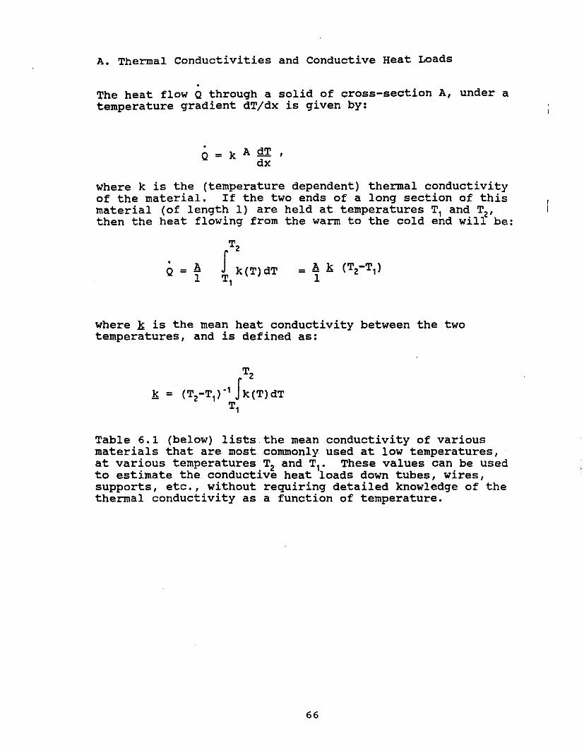
A. Thermal Conductivities and Conductive Heat Loads
The heat flow Q through a solid of cross-section A, under atemperature gradient dT/dx is given by:
where k is the (temperature dependent) thermal conductivityof the material. If the two ends of a long section of thismaterial (of length 1) are held at temperatures T, and T2,then the heat flowing from the warm to the cold end will be:
Q = A1
T2
J k(T) dTT,
where k is the mean heat conductivity between the twotemperatures, and is defined as:
T2
k = (T2-T,)-' Jk(T)dTT,
Table 6.1 (below) lists the mean conductivity of variousmaterials that are most commonly used at low temperatures,at various temperatures T2 and T,. These values can be usedto estimate the conductive heat loads down tubes, wires,supports, etc., without requiring detailed knowledge of thethermal conductivity as a function of temperature.
66
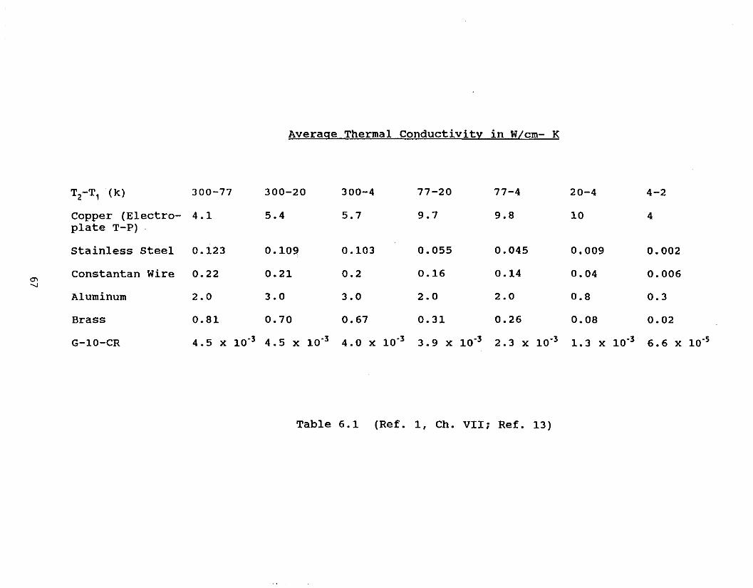
Average Thermal Conductivity in W/cm- K
TZ-T1 (k) 300-77 300-20 300-4 77-20 77-4 20-4 4-2
Copper (Electro- 4.1 5.4 5.7 9.7 9.8 10 4plate T-P)
stainless steel 0.123 0.109 0.103 0.055 0.045 0.009 0.002
Constantan Wire 0.22 0.21 0.2 0.16 0.14 0.04 0.006en
" Aluminum 2.0 3.0 3.0 2.0 2.0 0.8 0.3
Brass 0.81 0.70 0.67 0.31 0.26 0.08 0.02
G-10-CR 4.5 x 10'3 4.5 X 10.3 4.0 X 10.3 3.9 X 10.3 2.3 X 10.3 1. 3 X 10.3 6.6 X 10.5
Table 6.1 (Ref. 1, Ch. VII; Ref. 13)
B. Radiational Heat Loads
The radiational heat load from a warm surface at temperature Tzto a cooler surface at temperature T, may be epxressed as
Qr = S (TZ4 - T,4)/V
where S is the Stefan-Boltzmann constant (5.67 x 10.8 W/mz-K") andV (view factor) defined by (Ref. 7, Ch. 7 and Ref. 6, Ch. 8),
e, and ez are the emissivities of the two surfaces, AJ and Aztheir areas, and Fz, is the configuration factor whiCh isdetermined by the relative geometry of the two surfaces.
For cylindrical metal dewars, two useful configuration factors tohave are those for concentric cylinders and for parallel discs.For long (compared to the radius) concentric cylinders, Fz, = 1.For two parallel discs of radii r, and r z, separated by adistance h,
. z zw~th X = 1 + (l+R,)/Rz ; R, = v,/h ; Rz = vz/h.
One can easily see that for a typical laboratory dewar withconcentric shields, the configuration factor for two paralleldiscs will still be a number in the order of 1. Thus, the viewfactor for both configurations can be approximated by
V = l/ezAz + (l-e,) lelA,
Combining this with reported values of emissivities as listedbelow, quick estimates can be made for the radiational heat loadsfrom room temperature, nitrogen temperature or helium temperaturesurfaces.
68

Experimental Values of Emissivities
Radiation From: 300 K to 77 K 77 K to 4.2 K
Al - anodized 0.78 0.67Al - oxidized 0.5Al - as found 0.12Al - mech. polished 0.1 0.06Al - electro polished 0.075 0.036
Cu - as found 0.12 0.06Cu - mech. polished 0.06 0.023
stainless Steel - as found 0.34 0.12Stainless Steel - mech. polished 0.12 0.03Stainless Steel - electro-polished 0.1 0.065Stainless steel - as found with Al foil 0.056 0.011
Table 6.2 (Ref. 14)
C. Thermal Expansion
When a cryostat is cooled down to helium temperatures, thevarious components will contract, and it is useful to know therelative contraction for the various materials that are typicallyused in such cryostats. Most of the contraction usually occurswhen the cryostat has been cooled to liquid nitrogentemperatures. Thus most leaks that occur, when a cryostat iscooled, will show up at liquid nitrogen temperature. Knowledgeof the relative contraction is also helpful in designing jointsor mechanical contacts, thermal contacts or standoffs at lowtemperature.
Material
AluminumCopper304 Stainless SteelBrass (70 cu, 30 Zn)Brass (65 Cu, 35 Zn)G-l0CR (warp)G-l0CR (normal)NylonTeflonFused Silicon
Thermal Expansion Data
Percentage Change in Length(room temperature to 4.2 K)
0.4150.3240.3060.3690.3840.2410.7061. 392.140.0032
Table 6.3 (Ref. 12, Ch. 3 and Ref. 1, App. IX)
69

D. Experimental Data for Cooldown
The following lists information about common eryogens and metalsused in commercial eryostats, that is helpful in estimating theamount of cryogen required for eooldown to helium temperatures.
Experimental Data for Helium and Nitrogen
Normal Liquid Density Heat of Volume of GasBoiling at Boilin¥. Point Vaporization at STP fromPoint (glom l (Joule/em7) 1 liquid liter
He3 3.2 K 0.06 0.48 449 liters
He4 4.2 K 0.13 2.6 740 liters
N2 77.4 K 0.81 160 682 liters
Table 6.4 (Ref. 3, Ch. 8)
Densities of SIS, Cu, and Al
Stainless steelCopperAluminum
7.86 glee8.96 glee2.70 glee
Table 6.5 (Ref. 3, Ch. 3)
70
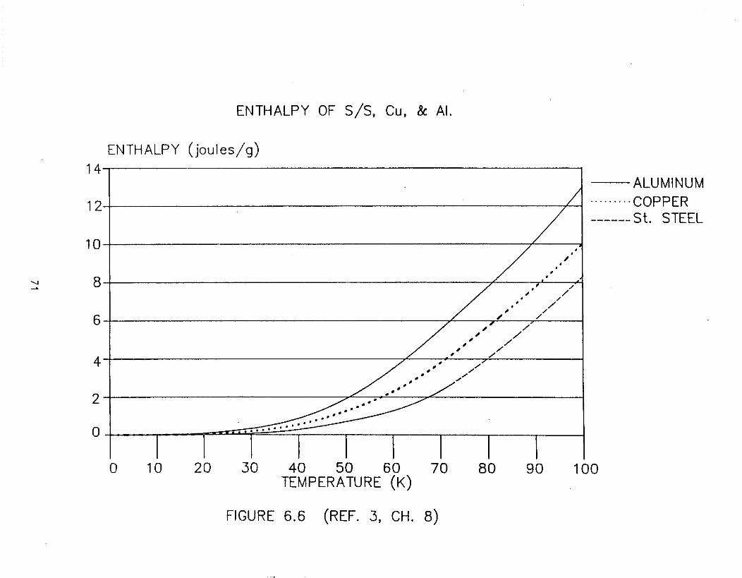
ENTHALPY OF 5/5, Cu, & AI.
--ALUMINUM····· .. ··COPPER------ St. STEEL
••,.••.
• ,/
,/ /. ,/.• /,/ ,/, /, /,//,/
,/,/ /
,/ /• .-•• .-
• • /'•.'.'2
4
6
12
ENTHALPY (joules/g)14
10
...... 8
o
o 10 20 30 40 50 60 70TEMPERATURE (K)
FIGURE 6.6 (REF. 3, CH. 8)
80 90 100

10 I I I I I i 7i10 COPPER
I I
AMOUNT OF HELIUM TO COOL COMMON· METALS
lITRES OF LIQUID HELIUM PER KILOGRAM OF METAL
STAINLESS STEEL10
ALUMINUM
1
-.10 I I r If <' <' ¥ I I I/v77
1
-,:10 I I f1///U'/)V I I
1
10-' 10-'1 VOl I L---l-J 10-" [ ( J I I I Io 40 0 40 eo 120 0 40 eo 120
10-'1 I t7r//XJ I I I
"N
T(K) T(K) T(K)
FIGURE 6.7 (REF. 3, CH. 3)
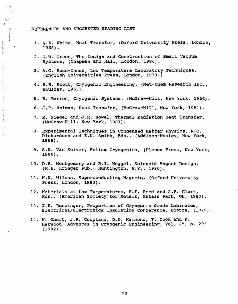
REFERENCES AND SUGGESTED READING LIST
1. G.K. White, Heat Transfer, (Oxford University Press, London,1968).
2. G.W. Green, The Design and Construction of Small VacuumSystems, (Chapman and Hall, London, 1986).
3. A.C. Rose-Innes, Low Temperature Laboratory Techniques,(English Universities Press, London, 1973.)
4. R.B. scott, Cryogenic Engineering, (Met-Chem Research Inc.,Boulder, 1963).
5. R. Barron, Cryogenic systems, (McGraW-Hill, New York, 1966).
6. J.P. Holman, Heat Transfer, (McGraw-Hill, New York, 1981).
7. R. Siegel and J.R. Howel, Thermal Radiation Heat Transfer,(McGraw-Hill, New York, 1981).
8. Experimental Techniques in Condensed Matter Physics, R.C.Richardson and E.N. Smith, Eds., (Addison-Wesley, New York,1988) •
9. S.W. Van Sciver, Helium Cryogenics, (Plenum Press, New York,1986).
10. D.B. Montgomery and R.J. Weggel, Solenoid Magnet Design,(R.E. Krieger Pub., Huntington, N.Y., 1980).
11. M.N. Wilson, Superconducting Magnets., (Oxford UniversityPress, London, 1983).
12. Materials at Low Temperatures, R.P. Reed and A.F. Clark,Eds., (American Society for Metals, Metals Park, OH, 1983).
13. J.R. Benzinger, Properties of cryogenic Grade Laminates,Electrical/Electronics Insulation conference, Boston, (1979).
14. W. Obert, J.R. Coupland, D.D. Hammond, T. Cook and K.Harwood, Advances in cryogenic Engineering, Vol. 25, p. 293(1982) •
73