Intro to Arena A Fourth Simulation. Model 4 This example is from Ch. 6 of Simulation with Arena, and...
32
Intro to Arena A Fourth Simulation
-
Upload
kenzie-mayhall -
Category
Documents
-
view
218 -
download
1
Transcript of Intro to Arena A Fourth Simulation. Model 4 This example is from Ch. 6 of Simulation with Arena, and...

Intro to Arena
A Fourth Simulation
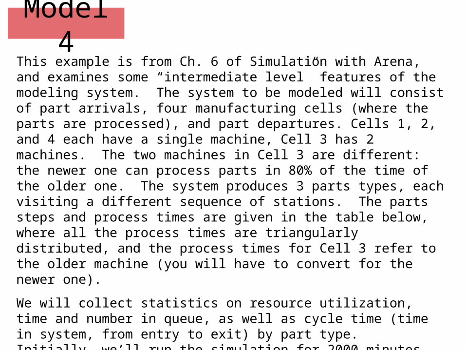
Model 4This example is from Ch. 6 of Simulation with Arena, and examines some “intermediate level” features of the modeling system. The system to be modeled will consist of part arrivals, four manufacturing cells (where the parts are processed), and part departures. Cells 1, 2, and 4 each have a single machine, Cell 3 has 2 machines. The two machines in Cell 3 are different: the newer one can process parts in 80% of the time of the older one. The system produces 3 parts types, each visiting a different sequence of stations. The parts steps and process times are given in the table below, where all the process times are triangularly distributed, and the process times for Cell 3 refer to the older machine (you will have to convert for the newer one).
We will collect statistics on resource utilization, time and number in queue, as well as cycle time (time in system, from entry to exit) by part type. Initially, we’ll run the simulation for 2000 minutes.

Model 4Parts Routings and Process Times.
P. Type C/T C/T C/T C/T C/T
1 1 2 3 4
6,8,10 5,8,10 15,20,25 8,12,16
2 1 2 4 2 3
11,13,15 4,6,8 15,18,21 6,9,12 27,33,39
3 2 1 3
7,9,11 7,10,13 18,23,28
The inter-arrival times between successive part arrivals (all types combined) are exponentially distributed with a mean of 13 minutes. Parts enter at the left, exit at the right, and move only in a clockwise direction through the system. For now we assume that the time to move between cells is 2 minutes.

Model 4Cell1Cell 2Cell 3Cell 4InOutInOutInOutInOutEnterExit

Model 4New ideas.
a) The three part types follow different process plans. In the previous models, they all followed the same plan, always going to the next station.
b) The two machines in Cell 3 are not identical. We must distinguish them.
c) We want to collect cycle times by part type. We would also like to use different icons for different part types, so we can distinguish them during the simulation.
We will use three new (to us) Arena attributes:
Station - variable name M
Sequence - variable name NS
Jobstep - variable name IS
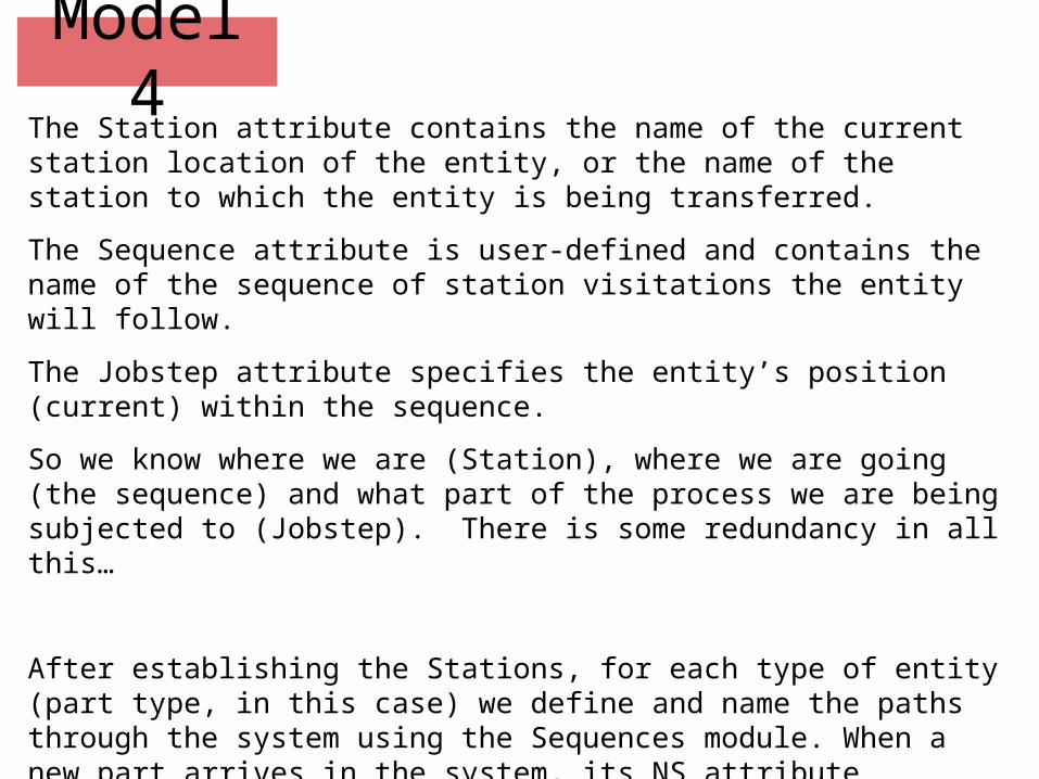
Model 4The Station attribute contains the name of the current station location of the entity, or the name of the station to which the entity is being transferred.
The Sequence attribute is user-defined and contains the name of the sequence of station visitations the entity will follow.
The Jobstep attribute specifies the entity’s position (current) within the sequence.
So we know where we are (Station), where we are going (the sequence) and what part of the process we are being subjected to (Jobstep). There is some redundancy in all this…
After establishing the Stations, for each type of entity (part type, in this case) we define and name the paths through the system using the Sequences module. When a new part arrives in the system, its NS attribute acquires the value of the appropriate sequence.

Model 4When the entity is ready to leave a station, we select the Seq option in the Leave Data area. At this point, the Jobstep (IS) is incremented by 1, the system, based on the current station and Jobstep, chooses the next station, sets all the appropriate attributes, and moves the part to the next station.
It is possible to re-assign sequence attributes: for example, a part that fails a test may have to be reworked, and so might have to start an entirely different sequence from the expected one right after the test.
Arena contains a module (the Variables module) that allows a user to define new global variables - to be used as needed. Another module (the Expressions module) allows the user to define expressions - and their associated values, which are computed every time the expression is used, since one would expect that the variables and attributes used in the expression will change from moment to moment. This would be analogous to variables and functions in a programming language.
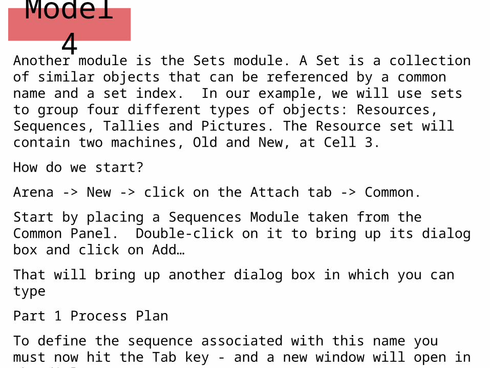
Model 4Another module is the Sets module. A Set is a collection of similar objects that can be referenced by a common name and a set index. In our example, we will use sets to group four different types of objects: Resources, Sequences, Tallies and Pictures. The Resource set will contain two machines, Old and New, at Cell 3.
How do we start?
Arena -> New -> click on the Attach tab -> Common.
Start by placing a Sequences Module taken from the Common Panel. Double-click on it to bring up its dialog box and click on Add…
That will bring up another dialog box in which you can type
Part 1 Process Plan
To define the sequence associated with this name you must now hit the Tab key - and a new window will open in the dialog.

Model 4Recall that Part 1 goes through Cells 1, 2, 3, 4, and then exits the system. So hit Add… You will end up with another Dialog box entitled Steps, into which you will type Cell 1,and then you will click on Add… again (in the Assignments region at the bottom.)
You will end up with the dialogs on the next slide…

Model 4The Process Time is given in the table on the second slide (you must type it in), and it is represented by a triangular distribution. Type that in the Value window.
Click OK on both of these dialogs until you get back to the Sequences dialog box (the second), and hit Add… again, to add Cell2 to the sequence, along with the Assignment of its Process Time attribute, which uses
the triangular distribution TRIA(5, 8, 10). Repeat the steps for Cell 3 and Cell 4 (you can pick Process Time from the drop down list, once you have introduced it). Repeat also for Exit System - where you add only the station name, with no attributes.
Model 4You are now done with the sequences for Part 1. Since there are THREE types of parts, each with its own sequence and its own process distribution, before exiting the Sequences dialog, you must click on Add…, repeat the steps for Part 2 Process Plan, and for Part 3 Process Plan.
You can actually avoid some of the work using the Expressions Module.
Click on the Expressions button in Common, and place an Expressions module anywhere in the model area. Double-click on the Expressions box - a dialog will come up. Click on Add…, and another dialog will pop up.
Type Cell 1 Times in the Expression Name area, and hit the Tab key. More windows will appear.
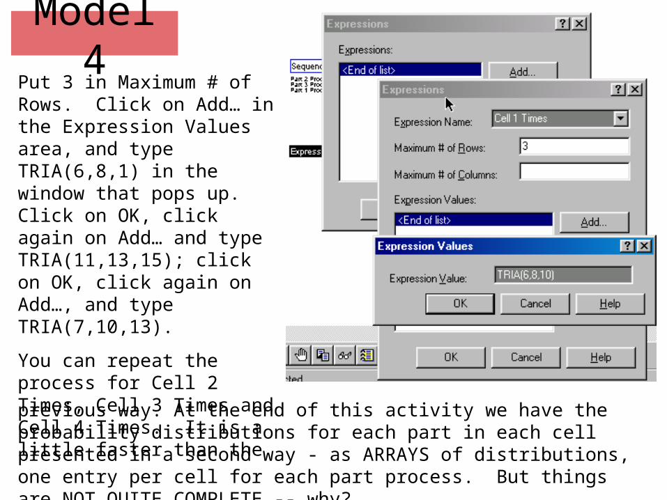
Model 4Put 3 in Maximum # of Rows. Click on Add… in the Expression Values area, and type TRIA(6,8,1) in the window that pops up. Click on OK, click again on Add… and type TRIA(11,13,15); click on OK, click again on Add…, and type TRIA(7,10,13).
You can repeat the process for Cell 2 Times, Cell 3 Times and Cell 4 Times. It is a little faster than the
previous way. At the end of this activity we have the probability distributions for each part in each cell presented in a second way - as ARRAYS of distributions, one entry per cell for each part process. But things are NOT QUITE COMPLETE -- why?

Model 4Problem: Cell 2 has different times for Part 2, depending on whether it is the first pass of Part 2 through Cell 2, or the second.
Problem: Cell 3 has two distinct machines with different process times.
The second problem can be solved by using the Variables module from the Common panel. If you don’t see the Variables button, click on the scroll tabs at the top of the panel. Then click on Variables and position a Variables entity on the model construction area

Model 4Double-click on the Variables entity; Add..; type Factor in the Variable list window; Tab; type 2 in the Maximum # of Rows window; Tab and the Columns window appears - leave it empty; Add..; type 0.8 in the Initial Value window; OK; Add…; type 1.0 in the Initial Value window (second value); OK; OK; Add…; type Transfer Time inthe Variable list window; tab; Add…; type 2 in the Initial Value window; OK; OK; OK.
Done…!!!
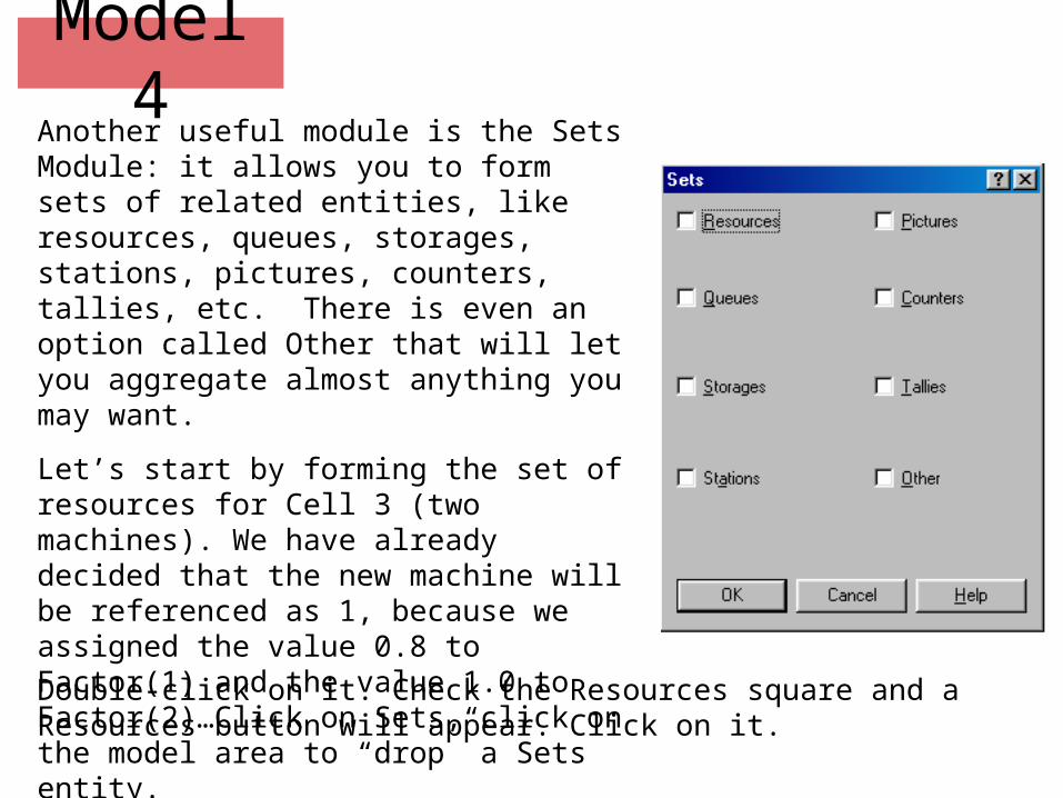
Model 4Another useful module is the Sets Module: it allows you to form sets of related entities, like resources, queues, storages, stations, pictures, counters, tallies, etc. There is even an option called Other that will let you aggregate almost anything you may want.
Let’s start by forming the set of resources for Cell 3 (two machines). We have already decided that the new machine will be referenced as 1, because we assigned the value 0.8 to Factor(1) and the value 1.0 to Factor(2)…Click on Sets, click on the model area to “drop” a Sets entity.
Double-click on it. Check the Resources square and a Resources button will appear. Click on it.
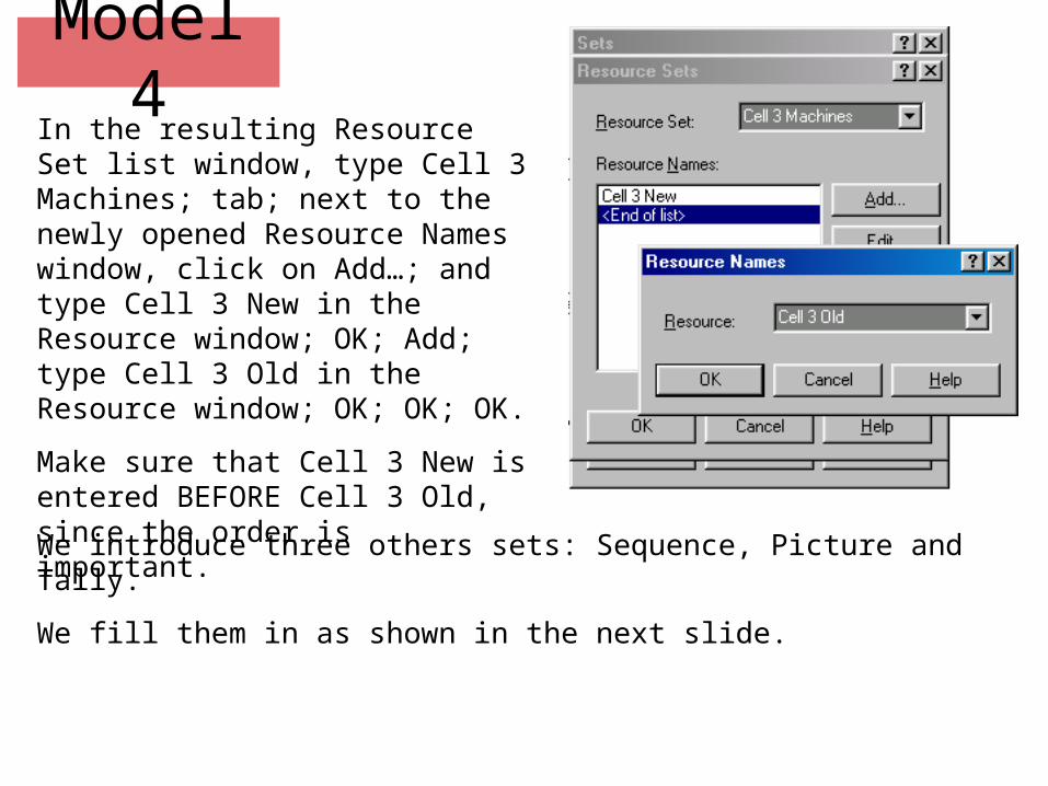
Model 4In the resulting Resource Set list window, type Cell 3 Machines; tab; next to the newly opened Resource Names window, click on Add…; and type Cell 3 New in the Resource window; OK; Add; type Cell 3 Old in the Resource window; OK; OK; OK.
Make sure that Cell 3 New is entered BEFORE Cell 3 Old, since the order is important.
We introduce three others sets: Sequence, Picture and Tally.
We fill them in as shown in the next slide.
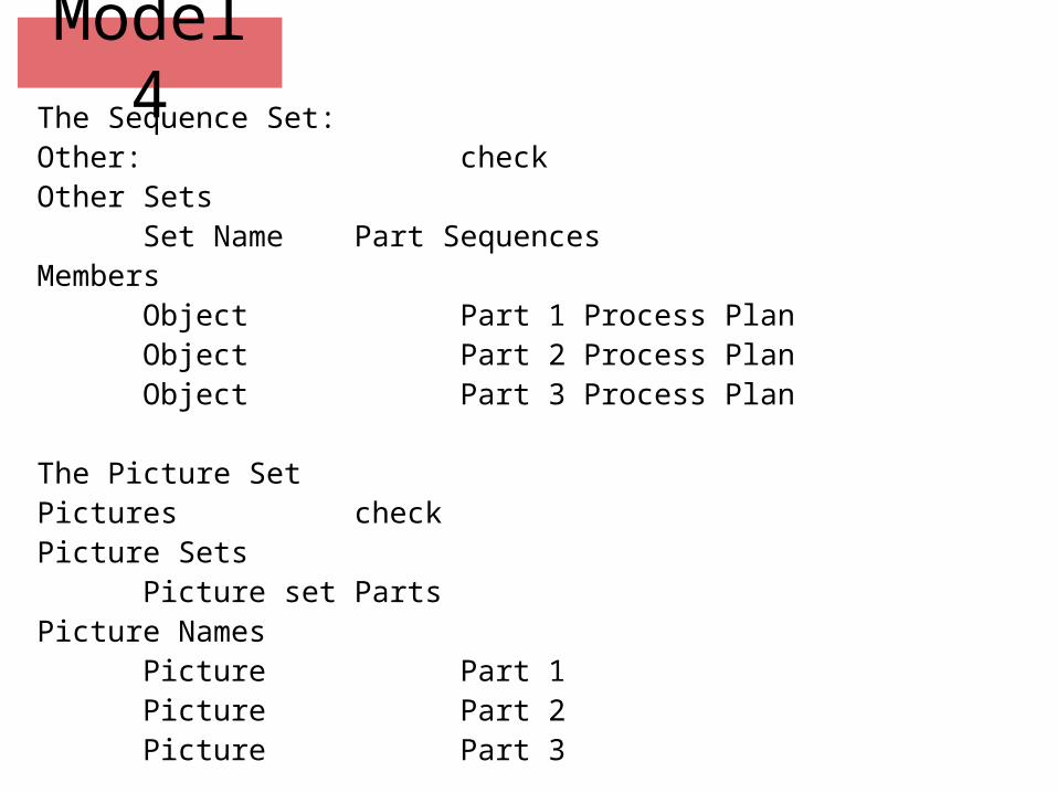
Model 4The Sequence Set:Other: checkOther Sets
Set Name Part SequencesMembers
Object Part 1 Process PlanObject Part 2 Process PlanObject Part 3 Process Plan
The Picture SetPictures checkPicture Sets
Picture set PartsPicture Names
Picture Part 1Picture Part 2Picture Part 3

Model 4The Tally SetTallies checkTally Sets
Tally Set Part Cycle timeTally Names
Tally Part 1 Cycle TimeTally Part 2 Cycle TimeTally Part 3 Cycle Time
Make sure you fill them in. Finally add a Simulate Module:Project
Title Small Manufacturing SystemAnalyst <your name>
ReplicateLength of Replication2000

Model 4We have all kinds of modules, but we are missing all the Logic Modules that represent Parts Arrivals, Cells and Parts Departures.
We start with an Arrive Module. Click on the Arrive button in the Common panel, click the cross-hairs in the model design area, double-click on the Arrive box, and fill in as indicated on the right.
Exponential arrivals; and the Sequence button has been checked. We are NOT done with this dialog, yet. Click on the Assign… button, to take care of the sequence assignments, and other things.
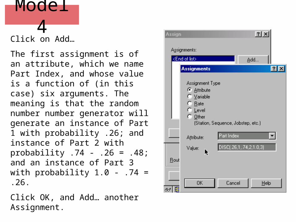
Model 4Click on Add…
The first assignment is of an attribute, which we name Part Index, and whose value is a function of (in this case) six arguments. The meaning is that the random number number generator will generate an instance of Part 1 with probability .26; and instance of Part 2 with probability .74 - .26 = .48; and an instance of Part 3 with probability 1.0 - .74 = .26.
Click OK, and Add… another Assignment.
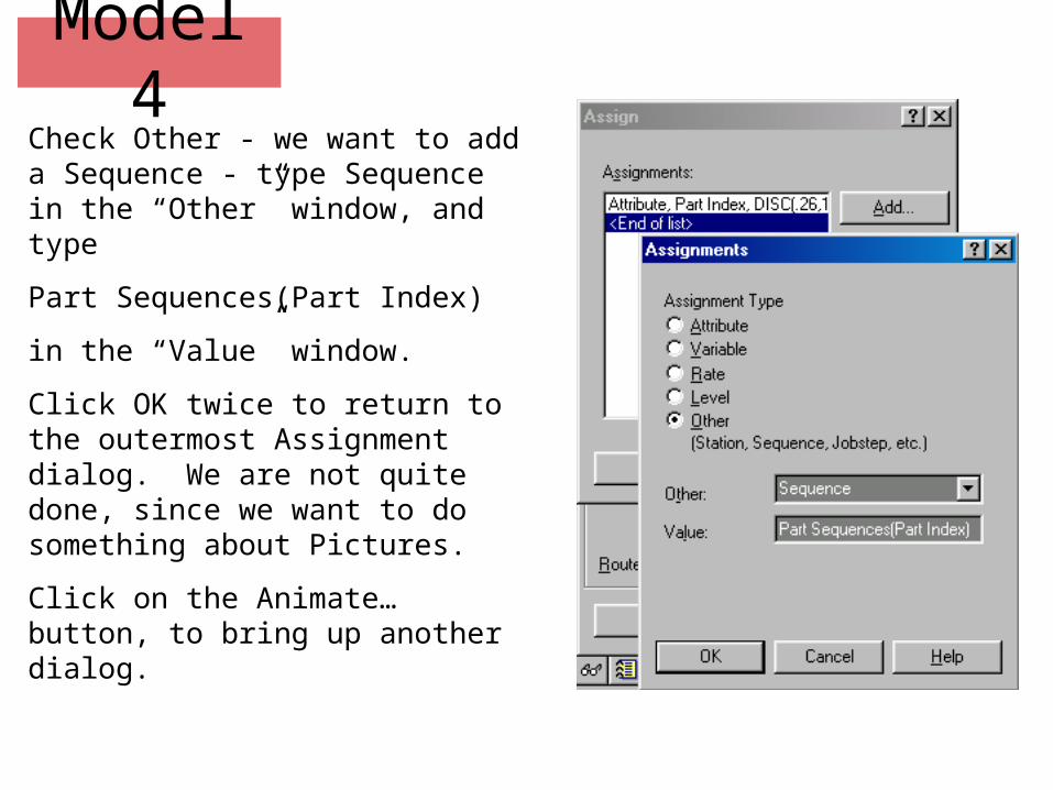
Model 4Check Other - we want to add a Sequence - type Sequence in the “Other” window, and type
Part Sequences(Part Index)
in the “Value” window.
Click OK twice to return to the outermost Assignment dialog. We are not quite done, since we want to do something about Pictures.
Click on the Animate… button, to bring up another dialog.

Model 4The dialog on the left appears, and you must transform it into the dialog on the right. Choose from the drop lists - you don’t need to type.
Recall we defined a set called “Parts”, indexed by “Part Index”.
Click on enough OKs

Model 4The just completed Arrive module creates the parts, determines the part type, assigns the proper sequence, and automatically routes the part to the next station in its sequence.All cells, except for Cell 3, can be modeled easily using the Server module. Let’s do it for Cell 1.
Cell 2 and Cell 4 have different behaviors depending on the part and the time the part is processed, but can still be modeled this way.

Model 4
An identical dialog - except for having Cell 4 - will take care of Cell 4. The Process Time was defined as associated to the sequence, and will be used correctly.
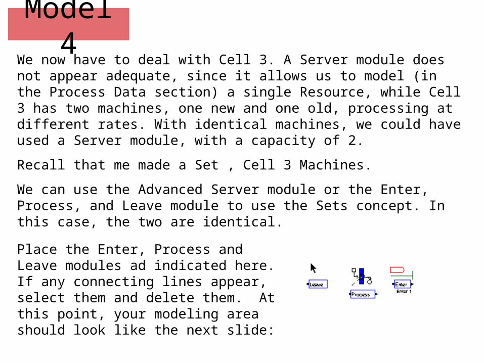
Model 4We now have to deal with Cell 3. A Server module does not appear adequate, since it allows us to model (in the Process Data section) a single Resource, while Cell 3 has two machines, one new and one old, processing at different rates. With identical machines, we could have used a Server module, with a capacity of 2.
Recall that me made a Set , Cell 3 Machines.
We can use the Advanced Server module or the Enter, Process, and Leave module to use the Sets concept. In this case, the two are identical.
Place the Enter, Process and Leave modules ad indicated here. If any connecting lines appear, select them and delete them. At this point, your modeling area should look like the next slide:

Model 4
We start by filling in the dialog boxes associated with the Enter module: double-click, select Station and choose Cell 3 from the drop-down list.
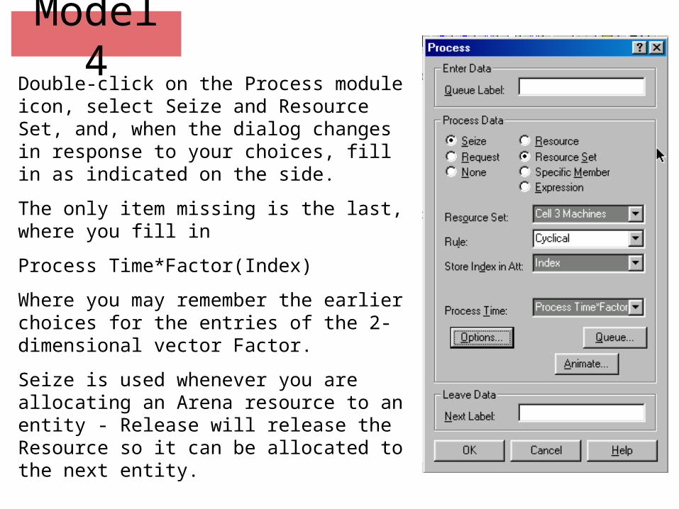
Model 4Double-click on the Process module icon, select Seize and Resource Set, and, when the dialog changes in response to your choices, fill in as indicated on the side.
The only item missing is the last, where you fill in
Process Time*Factor(Index)
Where you may remember the earlier choices for the entries of the 2-dimensional vector Factor.
Seize is used whenever you are allocating an Arena resource to an entity - Release will release the Resource so it can be allocated to the next entity.
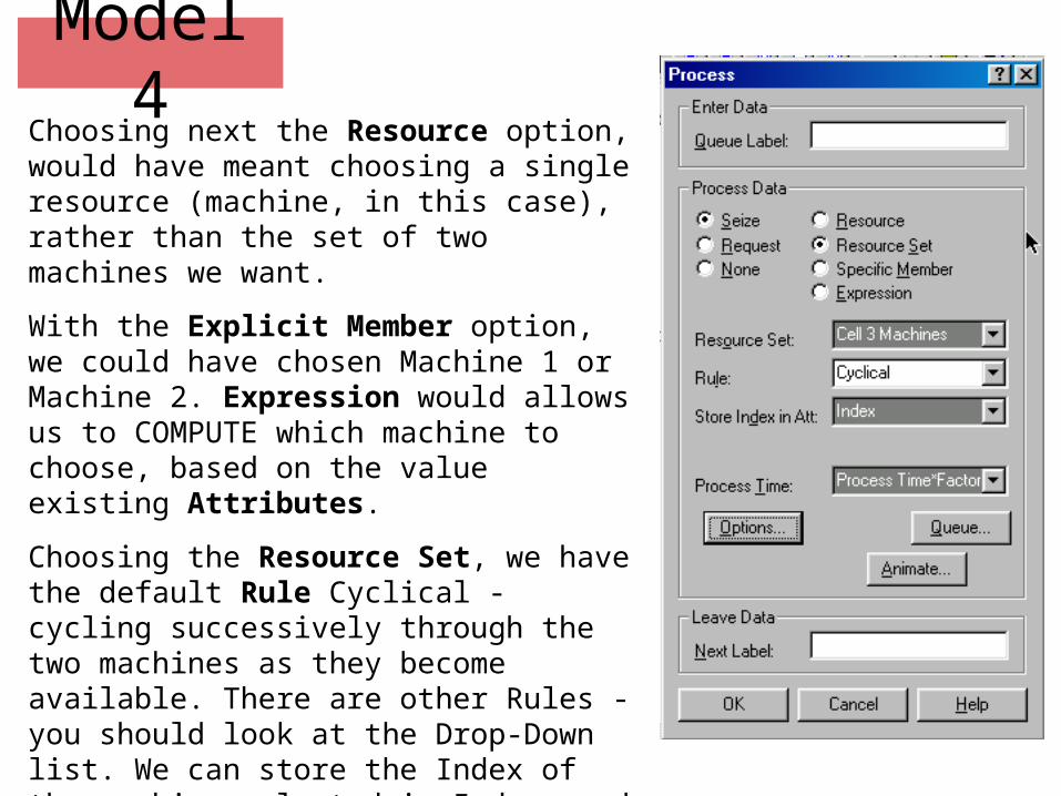
Model 4Choosing next the Resource option, would have meant choosing a single resource (machine, in this case), rather than the set of two machines we want.
With the Explicit Member option, we could have chosen Machine 1 or Machine 2. Expression would allows us to COMPUTE which machine to choose, based on the value existing Attributes.
Choosing the Resource Set, we have the default Rule Cyclical - cycling successively through the two machines as they become available. There are other Rules - you should look at the Drop-Down list. We can store the Index of the machine selected in Index, and we finally set up the Process Time.

Model 4We can now double-click on the Leave module and fill in its dialog box as indicated on the right.
After hitting OK, we can now connect the three modules.
First note that the boxes for Enter and Process have two small attachments (zoom in in you have trouble observing them): the triangle denotes Exit, while the square denotes Enter. You can move their positions by “click-and-drag” so that they are conveniently located.
Find the “Module Connect” button on the tool-bar, start at Exit of the “Enter” module, and draw a poly-line through “Process” to Enter of “Leave”.

Model 4Next place two Resources at the right of the Leave, Process, Enter triple, and fill their dialog boxes as next. After filling the two Resource dialogs, we are almost done. We need only to Depart. Allocate a Depart module, at the right and above the Resources (for convenience - it does not really matter where), and fill it:Enter Data Station Exit SystemTally Tally Set Member select Tally Set Part Cycle Times Set Index Part IndexType of Statistics Interval Enter Time

Model 4If we try to run the model as it is, we will get an error. The problem is that we have not associated a picture to each part.
Double-click on the red dot over the “Simulation” box. You may have to try carefully, since the dot is small. Click on the Default rectangle. “Default” will appear in the “Value” window. Use the pull-down list to select Part 1. Next click the Copy button and select Part 2. Another Copy, and Part 3. OK.
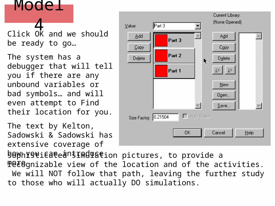
Model 4Click OK and we should be ready to go…
The system has a debugger that will tell you if there are any unbound variables or bad symbols… and will even attempt to Find their location for you.
The text by Kelton, Sadowski & Sadowski has extensive coverage of how you can introduce moresophisticated simulation pictures, to provide a recognizable view of the location and of the activities. We will NOT follow that path, leaving the further study to those who will actually DO simulations.