INTRINSICALLY SAFE Low Profile Load Cells for … · INTRINSICALLY SAFE Low PRoFILE LoAd CELLS FoR...
4
F-1 LOAD CELLS F INTRINSICALLY SAFE LOW PROFILE LOAD CELLS FOR HAZARDOUS LOCATIONS STANDARD AND METRIC MODELS U FM Intrinsically Safe Rating Standard U 4 to 20 mA Output U 5-Point NIST Traceable Calibration Included U 0.25% Interchangeability U All Stainless Steel Construction for Harsh Industrial Environments U Heavy-Duty Industrial Design U Low Profile for Easy Installations Tension or Compression 50 to 750,000 lb Capacities 25 to 10,000 kgf Metric Models LC412/LCM412-IS Series The LC412-IS Series intrinsically safe load cells are FM rated intrinsically safe for use in hazardous locations. They are available with 5 different electrical terminations. Three connector options and 2 cable options, one of which is a submersible waterproof cable. Standard models have an amplified 4 to 20 mA output for uni-directional applications and a 4-12-20 mA output for bi-directional applications. LC412-IS, twist-lock termination shown. SPECIFICATIONS Excitation mV/V Output: 10-28 Vdc Output (One Direction C2): 4 to 20 mA, ±10% adjustable Output (Two Directions BC2): 4-12-20 mA, ±10% adjustable Nonlinearity (%F.S.O.): 0.10 Hysterisis (%F.S.O.): 0.10 Repeatability (%F.S.O.): 0.05 Zero Balance: 4 mA, 10%, -2% adjustable TYPE AGENCY APPROVAL LISTINGS Intrinsically Safe (US and Canada) FM Hazardous (Classified) Location, Rated Intrinsically Safe, Securite Intrinsique Class I, II, III, Division 1 Gr A, B, C, D, E, F, G Class I, Zone 0 Aex ia IIc (US), Class I, Zone 0 Ex ia IIC (Canada), T4, Ta = -40 to 75°C Non-Incendive FM FM Hazardous (Classified) Location, Rated Non-Incendive Class I Division 2 Groups A, B, C, D (US and Canada) T4, Ta = -40 to 75°C, Conduit electrical connections only AGENCY APPROVALS Operating Temperature: -40 to 75°C (-40 to 167°F) Compensated Temperature: 16 to 71°C (60 to 160°F) Temperature Effects: Zero (%FSO/°F): ±0.005 (±0.009%FSO/°C) Span (%Reading/°F): ±0.005 (±0.009%Reading/°C) Safe Overload (% of Capacity): 150 Ultimate Overload (% of Capacity): 300 Material: Stainless steel NOTE: Please refer to www.omega.com/approvals/ for downloadable copies of FM Approvals Certificate of Compliance and installation control drawings. Standard APPROVED US C FM Please Note: Not for export, USA and Canada only
Transcript of INTRINSICALLY SAFE Low Profile Load Cells for … · INTRINSICALLY SAFE Low PRoFILE LoAd CELLS FoR...
F-1
LO
AD
CE
LL
S
Fz I
R
INTRINSICALLY SAFE Low PRoFILE LoAd CELLS FoR HAzARdouS LoCATIoNSSTANdARd ANd mETRIC modELS
U FM Intrinsically Safe Rating Standard
U 4 to 20 mA OutputU 5-Point NIST
Traceable Calibration Included
U 0.25% InterchangeabilityU All Stainless Steel
Construction for Harsh Industrial Environments
U Heavy-Duty Industrial Design
U Low Profile for Easy Installations
Tension or Compression50 to 750,000 lb Capacities25 to 10,000 kgf metric models
LC412/LCm412-IS Series
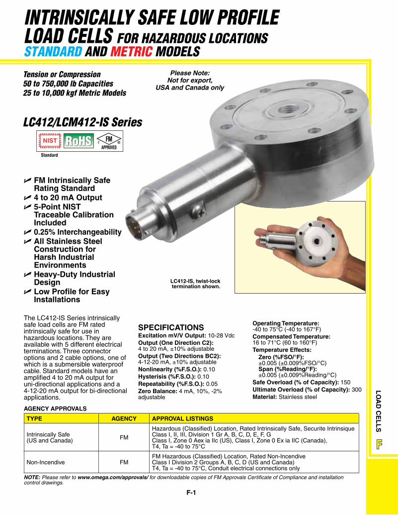
The LC412-IS Series intrinsically safe load cells are FM rated intrinsically safe for use in hazardous locations. They are available with 5 different electrical terminations. Three connector options and 2 cable options, one of which is a submersible waterproof cable. Standard models have an amplified 4 to 20 mA output for uni-directional applications and a 4-12-20 mA output for bi-directional applications.
LC412-IS, twist-lock termination shown.
SPECIFICATIONSExcitation mV/V Output: 10-28 VdcOutput (One Direction C2): 4 to 20 mA, ±10% adjustableOutput (Two Directions BC2): 4-12-20 mA, ±10% adjustableNonlinearity (%F.S.O.): 0.10Hysterisis (%F.S.O.): 0.10 Repeatability (%F.S.O.): 0.05 Zero Balance: 4 mA, 10%, -2% adjustable
TyPE AgENCy APPROVAL LISTINgS
Intrinsically Safe(US and Canada) FM
Hazardous (Classified) Location, Rated Intrinsically Safe, Securite IntrinsiqueClass I, II, III, Division 1 Gr A, B, C, D, E, F, GClass I, Zone 0 Aex ia IIc (US), Class I, Zone 0 Ex ia IIC (Canada),T4, Ta = -40 to 75°C
Non-Incendive FMFM Hazardous (Classified) Location, Rated Non-IncendiveClass I Division 2 Groups A, B, C, D (US and Canada)T4, Ta = -40 to 75°C, Conduit electrical connections only
AgENCy APPROVALS
Operating Temperature: -40 to 75°C (-40 to 167°F)Compensated Temperature: 16 to 71°C (60 to 160°F)Temperature Effects: Zero (%FSO/°F): ±0.005 (±0.009%FSO/°C) Span (%Reading/°F): ±0.005 (±0.009%Reading/°C)Safe Overload (% of Capacity): 150Ultimate Overload (% of Capacity): 300Material: Stainless steel
Note: Please refer to www.omega.com/approvals/ for downloadable copies of FM Approvals Certificate of Compliance and installation control drawings.
Standard
APPROVEDUSC FM
Please Note: Not for export,
USA and Canada only
LO
AD
CE
LL
S
Fz I
R
F-2
INTRINSICALLY SAFE LoAd CELLS
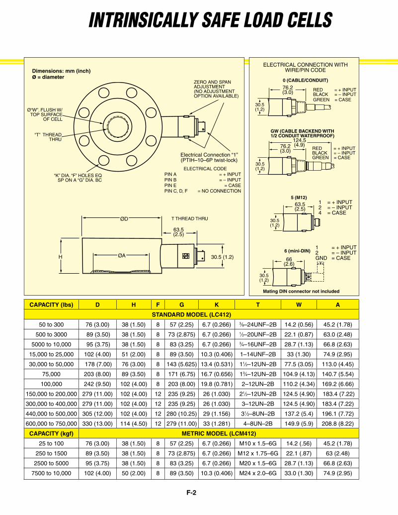
CAPACITy (lbs) D H F g K T W A
STANDARD MODEL (LC412)
50 to 300 76 (3.00) 38 (1.50) 8 57 (2.25) 6.7 (0.266) 3⁄8–24UNF–2B 14.2 (0.56) 45.2 (1.78)
500 to 3000 89 (3.50) 38 (1.50) 8 73 (2.875) 6.7 (0.266) 1⁄2–20UNF–2B 22.1 (0.87) 63.0 (2.48)
5000 to 10,000 95 (3.75) 38 (1.50) 8 83 (3.25) 6.7 (0.266) 3⁄4–16UNF–2B 28.7 (1.13) 66.8 (2.63)
15,000 to 25,000 102 (4.00) 51 (2.00) 8 89 (3.50) 10.3 (0.406) 1–14UNF–2B 33 (1.30) 74.9 (2.95)
30,000 to 50,000 178 (7.00) 76 (3.00) 8 143 (5.625) 13.4 (0.531) 11⁄2–12UN–2B 77.5 (3.05) 113.0 (4.45)
75,000 203 (8.00) 89 (3.50) 8 171 (6.75) 16.7 (0.656) 13⁄4–12UN–2B 104.9 (4.13) 140.7 (5.54)
100,000 242 (9.50) 102 (4.00) 8 203 (8.00) 19.8 (0.781) 2–12UN–2B 110.2 (4.34) 169.2 (6.66)
150,000 to 200,000 279 (11.00) 102 (4.00) 12 235 (9.25) 26 (1.030) 21⁄2–12UN–2B 124.5 (4.90) 183.4 (7.22)
300,000 to 400,000 279 (11.00) 102 (4.00) 12 235 (9.25) 26 (1.030) 3–12UN–2B 124.5 (4.90) 183.4 (7.22)
440,000 to 500,000 305 (12.00) 102 (4.00) 12 280 (10.25) 29 (1.156) 31⁄2–8UN–2B 137.2 (5.4) 196.1 (7.72)
600,000 to 750,000 330 (13.00) 114 (4.50) 12 279 (11.00) 33 (1.281) 4–8UN–2B 149.9 (5.9) 208.8 (8.22)
CAPACITy (kgf) METRIC MODEL (LCM412)
25 to 100 76 (3.00) 38 (1.50) 8 57 (2.25) 6.7 (0.266) M10 x 1.5–6G 14.2 (.56) 45.2 (1.78)
250 to 1500 89 (3.50) 38 (1.50) 8 73 (2.875) 6.7 (0.266) M12 x 1.75–6G 22.1 (.87) 63 (2.48)
2500 to 5000 95 (3.75) 38 (1.50) 8 83 (3.25) 6.7 (0.266) M20 x 1.5–6G 28.7 (1.13) 66.8 (2.63)
7500 to 10,000 102 (4.00) 50 (2.00) 8 89 (3.50) 10.3 (0.406) M24 x 2.0–6G 33.0 (1.30) 74.9 (2.95)
gW (CABLE BACKEND WITH 1/2 CONDUIT WATERPROOF)
0 (CABLE/CONDUIT)
5 (M12)
6 (mini-DIN)
76.2 (3.0)
76.2 (3.0)
124.5 (4.9)
30.5 (1.2)
30.5 (1.2)
30.5 (1.2)
30.5 (1.2)
63.5(2.5)
66(2.6)
RED = + INPUTBLACK = – INPUTGREEN = CASE
RED = + INPUTBLACK = – INPUTGREEN = CASE
1 = + INPUT2 = – INPUT4 = CASE
1 = + INPUT2 = – INPUTGND = CASE
ELECTRICAL CONNECTION WITH WIRE/PIN CODEDimensions: mm (inch)
ø = diameter
“K” DIA. “F” HOLES EQ SP ON A “G” DIA. BC
T THREAD THRU
30.5 (1.2)
63.5(2.5)
ZERO AND SPAN ADJUSTMENT(NO ADJUSTMENT OPTION AVAILABLE)
ØD
H
“T” THREADTHRU
Ø“W”. FLUSH W/TOP SURFACE
OF CELL
Electrical Connection “1”(PTIH–10–6P twist-lock)
ELECTRICAL CODE PIN A = + INPUTPIN B = – INPUT PIN E = CASEPIN C, D, F = NO CONNECTION
ØA
Mating DIN connector not included
F-3
LO
AD
CE
LL
S
Fz I
R
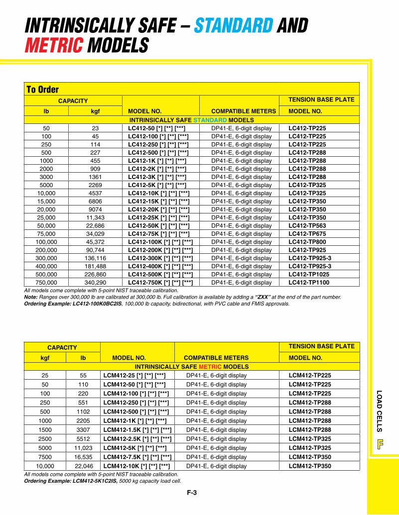
To Order CAPACITy TENSION BASE PLATE
lb kgf MODEL NO. COMPATIBLE METERS MODEL NO.
INTRINSICALLy SAFE STANDARD MODELS50 23 LC412-50 [*] [**] [***] DP41-E, 6-digit display LC412-TP225
100 45 LC412-100 [*] [**] [***] DP41-E, 6-digit display LC412-TP225250 114 LC412-250 [*] [**] [***] DP41-E, 6-digit display LC412-TP225500 227 LC412-500 [*] [**] [***] DP41-E, 6-digit display LC412-TP2881000 455 LC412-1K [*] [**] [***] DP41-E, 6-digit display LC412-TP2882000 909 LC412-2K [*] [**] [***] DP41-E, 6-digit display LC412-TP2883000 1361 LC412-3K [*] [**] [***] DP41-E, 6-digit display LC412-TP2885000 2269 LC412-5K [*] [**] [***] DP41-E, 6-digit display LC412-TP325
10,000 4537 LC412-10K [*] [**] [***] DP41-E, 6-digit display LC412-TP32515,000 6806 LC412-15K [*] [**] [***] DP41-E, 6-digit display LC412-TP35020,000 9074 LC412-20K [*] [**] [***] DP41-E, 6-digit display LC412-TP35025,000 11,343 LC412-25K [*] [**] [***] DP41-E, 6-digit display LC412-TP35050,000 22,686 LC412-50K [*] [**] [***] DP41-E, 6-digit display LC412-TP56375,000 34,029 LC412-75K [*] [**] [***] DP41-E, 6-digit display LC412-TP675100,000 45,372 LC412-100K [*] [**] [***] DP41-E, 6-digit display LC412-TP800200,000 90,744 LC412-200K [*] [**] [***] DP41-E, 6-digit display LC412-TP925300,000 136,116 LC412-300K [*] [**] [***] DP41-E, 6-digit display LC412-TP925-3400,000 181,488 LC412-400K [*] [**] [***] DP41-E, 6-digit display LC412-TP925-3500,000 226,860 LC412-500K [*] [**] [***] DP41-E, 6-digit display LC412-TP1025750,000 340,290 LC412-750K [*] [**] [***] DP41-E, 6-digit display LC412-TP1100
All models come complete with 5-point NIST traceable calibration.Note: Ranges over 300,000 lb are calibrated at 300,000 lb. Full calibration is available by adding a “ZXX” at the end of the part number.ordering example: LC412-100K0BC2IS, 100,000 lb capacity, bidirectional, with PVC cable and FMIS approvals.
INTRINSICALLY SAFE – STANdARd ANd mETRIC modELS
All models come complete with 5-point NIST traceable calibration.ordering example: LCM412-5K1C2IS, 5000 kg capacity load cell.
CAPACITy
COMPATIBLE METERS
TENSION BASE PLATE
kgf Ib MODEL NO. MODEL NO.
INTRINSICALLy SAFE METRIC MODELS25 55 LCM412-25 [*] [**] [***] DP41-E, 6-digit display LCM412-TP22550 110 LCM412-50 [*] [**] [***] DP41-E, 6-digit display LCM412-TP225100 220 LCM412-100 [*] [**] [***] DP41-E, 6-digit display LCM412-TP225250 551 LCM412-250 [*] [**] [***] DP41-E, 6-digit display LCM412-TP288500 1102 LCM412-500 [*] [**] [***] DP41-E, 6-digit display LCM412-TP2881000 2205 LCM412-1K [*] [**] [***] DP41-E, 6-digit display LCM412-TP2881500 3307 LCM412-1.5K [*] [**] [***] DP41-E, 6-digit display LCM412-TP2882500 5512 LCM412-2.5K [*] [**] [***] DP41-E, 6-digit display LCM412-TP3255000 11,023 LCM412-5K [*] [**] [***] DP41-E, 6-digit display LCM412-TP3257500 16,535 LCM412-7.5K [*] [**] [***] DP41-E, 6-digit display LCM412-TP350
10,000 22,046 LCM412-10K [*] [**] [***] DP41-E, 6-digit display LCM412-TP350
F-4
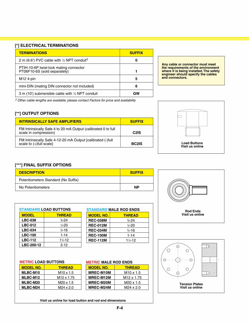
TERMINATIONS SUFFIX
2 m (6.6’) PVC cable with 1⁄2 NPT conduit† 0
PTIH-10-6P twist-lock mating connector PT06F10-6S (sold separately) 1
M12 4-pin 5
mini-DIN (mating DIN connector not included) 6
3 m (10') submersible cable with 1⁄2 NPT conduit gW
[*] ELECTRICAL TERMINATIONS
DESCRIPTION SUFFIX
Potentiometers Standard (No Suffix)
No Potentiometers NP
[***] FINAL SUFFIX OPTIONS
INTRINSICALLy SAFE AMPLIFIERS SUFFIX
FM Intrinsically Safe 4 to 20 mA Output (calibrated 0 to full scale in compression) C2IS
FM Intrinsically Safe 4-12-20 mA Output [calibrated (-)full scale to (+)full scale] BC2IS
[**] OUTPUT OPTIONS
MODEL NO. THREAD MREC-M10M M10 x 1.5 MREC-M12M M12 x 1.75 MREC-M20M M20 x 1.5 MREC-M24M M24 x 2.0
METRIC MALE ROD ENDSMETRIC LOAD BUTTONS
MODEL NO. THREAD MLBC-M10 M10 x 1.5 MLBC-M12 M12 x 1.75 MLBC-M20 M20 x 1.5 MLBC-M24 M24 x 2.0
Visit us online for load button and rod end dimensions
MODEL NO. THREAD REC-038M 3⁄8-24 REC-012M 1⁄2-20 REC-034M 3⁄4-16 REC-100M 1-14 REC-112M 11⁄2-12
STANDARD MALE ROD ENDS MODEL THREAD LBC-038 3⁄8-24 LBC-012 1⁄2-20 LBC-034 3⁄4-16 LBC-100 1-14 LBC-112 11⁄2-12 LBC-200-12 2-12
STANDARD LOAD BUTTONS
Load Buttons Visit us online
Rod
End
Art
wor
k/P
rodu
ct A
rt/P
ress
ure/
P-R
od E
nd
Rod Ends Visit us online
Tension PlatesVisit us online
Any cable or connector must meet the requirements of the environment where it is being installed. The safety engineer should specify the cables and connectors.
† Other cable lengths are available; please contact Factors for price and availability