InterVLAN Routing. Overview VLANs control broadcast domain size and keep local traffic local.
9
InterVLAN Routing
-
Upload
julia-boone -
Category
Documents
-
view
232 -
download
0
Transcript of InterVLAN Routing. Overview VLANs control broadcast domain size and keep local traffic local.
InterVLAN Routing
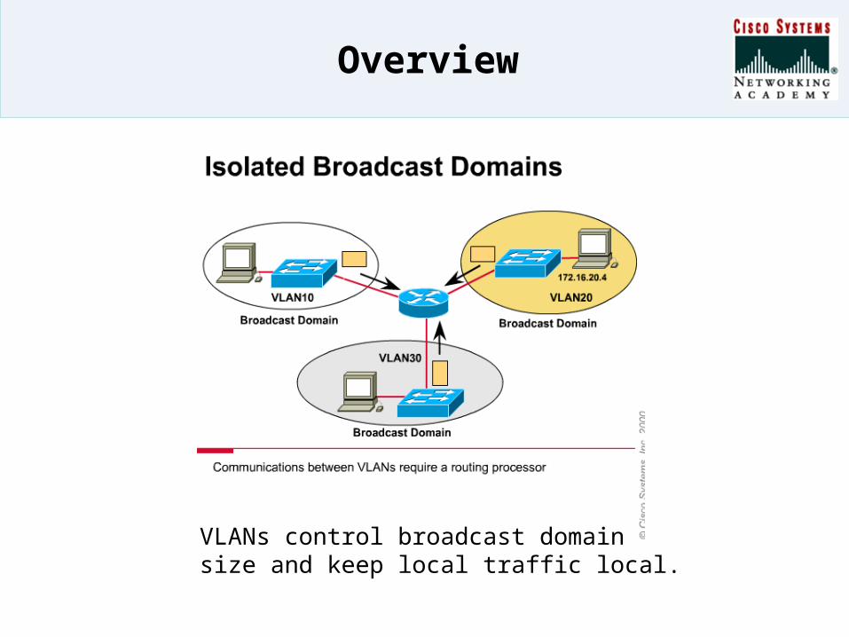
Overview
VLANs control broadcast domain size and keep local traffic local.

Key components of InterVLAN Routing
• Requirements for InterVLAN Routing
• VLAN capable switch• Router: External or integrated
within a switch• Router to VLAN connection
VL
AN
30
VL
AN
20
VL
AN
10
InterVLAN Routing Using a Route Processor
InternalRoute Processor
Layer 3 Switch
VL
AN
30
VL
AN
20
VL
AN
10
InterVLAN Routing Using a single link
VLAN 30VLAN 20VLAN 10
InterVLAN Routing Using one link per VLAN

External Routers
• Router-on-a-Stick• Trunk Link Advantages:
– Saves router and switch ports…saves money and reduces complexity.
– Scales to larger number of VLANs than one-link-per-VLAN design.
• Trunk Link Disadvantages:– Additional router overhead– Older IOS versions support
limited sets of features on trunked interfaces and may only support ISL trunking encapsulation.
Physical interfaceFastEthernet 0/0
Logical interfaceFastEthernet 0/0.10ip address 192.168.1.1
Logical interfaceFastEthernet 0/0.20ip address 192.168.2.1
Logical interfaceFastEthernet 0/0.30ip address 192.168.3.1
VLAN 30192.168.3.0
VLAN 20192.168.2.0
VLAN 10192.168.1.0
InterVLAN Routing using a single link
Trunk
Cisco Layer 3 Feature Cards
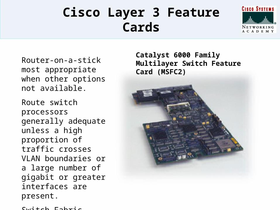
Catalyst 6000 Family Multilayer Switch Feature Card (MSFC2) Router-on-a-stick most
appropriate when other options not available.
Route switch processors generally adequate unless a high proportion of traffic crosses VLAN boundaries or a large number of gigabit or greater interfaces are present.
Switch Fabric Module adds switching capacity.
Configuring InterVLANRouting (1)
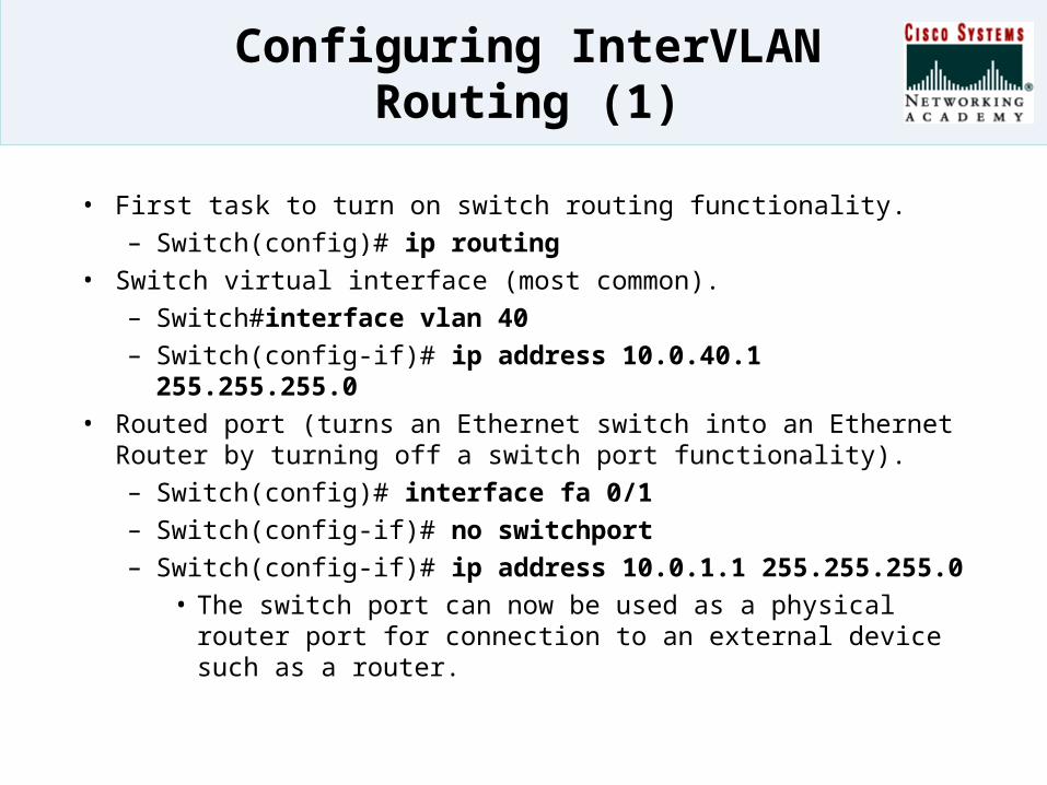
• First task to turn on switch routing functionality.– Switch(config)# ip routing
• Switch virtual interface (most common).– Switch#interface vlan 40– Switch(config-if)# ip address 10.0.40.1 255.255.255.0
• Routed port (turns an Ethernet switch into an Ethernet Router by turning off a switch port functionality).– Switch(config)# interface fa 0/1– Switch(config-if)# no switchport– Switch(config-if)# ip address 10.0.1.1 255.255.255.0
• The switch port can now be used as a physical router port for connection to an external device such as a router.
Configuring InterVLANRouting (2)
SiSi
Fa 0/1 Fa 0/0
WAN
Ext RouterS 0/0
Routed port
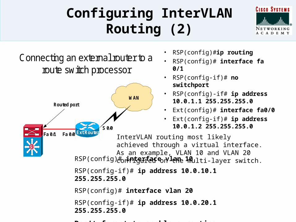
Connecting an external router to aroute switch processor
• RSP(config)#ip routing
• RSP(config)# interface fa 0/1
• RSP(config-if)# no switchport
• RSP(config)-if# ip address 10.0.1.1 255.255.255.0
• Ext(config)# interface fa0/0
• Ext(config-if)# ip address 10.0.1.2 255.255.255.0
InterVLAN routing most likely achieved through a virtual interface. As an example, VLAN 10 and VLAN 20 configured on the multi-layer switch.
RSP(config)# interface vlan 10
RSP(config-if)# ip address 10.0.10.1 255.255.255.0
RSP(config)# interface vlan 20
RSP(config-if)# ip address 10.0.20.1 255.255.255.0
Don’t forget to enable a routing protocol on both the RSP and External router.
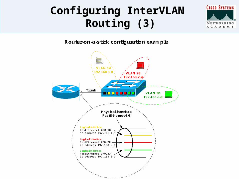
Configuring InterVLAN Routing (3)
Physical interfaceFastEthernet 0/0
Logical interfaceFastEthernet 0/0.10ip address 192.168.1.1
Logical interfaceFastEthernet 0/0.20ip address 192.168.2.1
Logical interfaceFastEthernet 0/0.30ip address 192.168.3.1
VLAN 30192.168.3.0
VLAN 20192.168.2.0
VLAN 10192.168.1.0
Router-on-a-stick configuration example
Trunk

Verifying InterVLAN Routing Configurations
SiSi
Fa 0/1 Fa 0/0
WAN
Ext RouterS 0/0
Routed port
Verifying interVLAN routing
10.0.10.0 / 24VLAN 10
10.0.20.0 / 24VLAN 20
• Switch# show ip route• Switch# show ip interface brief• Switch# show ip interface
fastethernet module/port– Can show if the port is
configured for routing• Switch# show ip interface
fastethernet module/port switchport– Either switchport information
will be displayed or “Switchport: Disabled” will indicate the port is likely configured for routing.