Interpretational challenges related to studies of chalk ...
16
Challenges related to studies of chalk particle surfaces in SEM and TEM · 151 Interpretational challenges related to studies of chalk particle surfaces in scanning and transmission electron microscopy MORTEN LETH HJULER, VIDAR FOLKE HANSEN & IDA LYKKE FABRICIUS Hjuler, M.L., Hansen, V.F. & Fabricius, I.L. 2018. Interpretational challenges related to studies of chalk particle surfaces in scanning and transmission electron microscopy. © 2018 by Bulletin of the Geological Society of Denmark, Vol. 66, pp. 151–165. ISSN 2245-7070. (www.2dgf.dk/publikationer/ bulletin). https://doi.org/10.37570/bgsd-2018-66-07 Scanning and transmission electron microscopy (SEM and TEM) are capable of characterising the morphology and structure of sub-micron size substances attached to chalk particle surfaces. Some characteristics, however, may originate from sample preparation or reflect interaction between sample and the electron beam. Misinterpretation of surface features may lead to wrong conclusions regarding grain surface properties and cementation level and thus to erroneous characterisation of hydrocarbon reservoirs with respect to e.g. wettability, mechanical strength and maximum burial depth. In SEM, conductive coatings may mask surface details or generate artificial ornamentations, and carbon adhesive discs may cause the chalk surface to be covered with a thin carbon film. Electron beam acceleration voltage controls the degree of detail revealed by the electron beam, but in SEM a high electron beam acceleration voltage may provoke bending or curling of ultrathin particles. Recent organic filaments may be confused with clay flakes, and authigenic non-carbonate minerals may have formed in the pore fluid and settled during fluid removal. In TEM, the high acceleration voltage may cause beam damage to calcite and transform the outermost atomic layers into Ca oxide. Thin graphite membranes observed by TEM may be contamination from the carbon film supporting the sample, and overlapping chalk particles in samples formed by drying of a suspension may give the impression of being cemented together. In TEM residual adhesive from the ion-milling process can be confused with cementation features. Keywords: Scanning electron microscopy, transmission electron microscopy, chalk, surface coating, surface ornamentation, image interpretation. Morten Leth Hjuler, Geological Survey of Denmark and Greenland (GEUS), Øster Voldgade 10, DK-1350 Copenhagen K, Denmark [present e-mail: [email protected]]. Vidar Folke Hansen [vidar.hansen@uis. no], Department of Mechanical and Structural Engineering and Materials Science, University of Stavanger, N-4036 Stavanger, Norway. Ida Lykke Fabricius [[email protected]], Department of Civil Engineering, Technical University of Denmark, Nordvej, Building 119, DK-2800 Kgs. Lyngby, Denmark. Oil recovery from chalk reservoirs in the North Sea is governed by the low permeability of the chalk matrix where significant amounts of oil are retained within the micrometre- or nanometre-sized pores. Oil recov- ery is further controlled by the properties of the parti- cle surface in terms of its affinity towards various pore fluids. The chalk surface may vary from completely oil-wet over mixed-wet to completely water-wet de- pending on factors such as type of pore fluid and its affinity towards calcite or e.g. clay minerals covering the calcite surface. Further, the surface area available for wetting may be controlled by the amount, type and distribution of clay and silica minerals (Røgen & Fabricius 2002) and by the degree of diagenesis, which in turn is controlled by maximum burial depth and timing of oil invasion (Hjuler & Fabricius 2009). In order to improve recovery efficiency, various im- proved oil recovery (IOR) and enhanced oil recovery (EOR) techniques are being tested and employed. In this context, understanding the properties of chalk particle surfaces is crucial and reliable characterisa- tions are necessary. Chalk is a granular material which seems rather homogenous to the naked eye, but on closer scrutiny visual traces of e.g. bioturbation, hardgrounds and diagenetic alterations are revealed. Microscopically, the heterogeneous appearance of chalk is further increased. Microfossils, remains of larger fossils and clasts of non-carbonates are unevenly distributed in a matrix of partly or completely disintegrated nanno- Received 1 December 2017 Accepted in revised form 1 April 2018 Published online 31 August 2018
Transcript of Interpretational challenges related to studies of chalk ...

Challenges related to studies of chalk particle surfaces in SEM and TEM · 151
Interpretational challenges related to studies of chalk particle surfaces in scanning and transmission electron microscopyMORTEN LETH HJULER, VIDAR FOLKE HANSEN & IDA LYKKE FABRICIUS
Hjuler, M.L., Hansen, V.F. & Fabricius, I.L. 2018. Interpretational challenges related to studies of chalk particle surfaces in scanning and transmission electron microscopy. © 2018 by Bulletin of the Geological Society of Denmark, Vol. 66, pp. 151–165. ISSN 2245-7070. (www.2dgf.dk/publikationer/bulletin). https://doi.org/10.37570/bgsd-2018-66-07
Scanning and transmission electron microscopy (SEM and TEM) are capable of characterising the morphology and structure of sub-micron size substances attached to chalk particle surfaces. Some characteristics, however, may originate from sample preparation or reflect interaction between sample and the electron beam. Misinterpretation of surface features may lead to wrong conclusions regarding grain surface properties and cementation level and thus to erroneous characterisation of hydrocarbon reservoirs with respect to e.g. wettability, mechanical strength and maximum burial depth. In SEM, conductive coatings may mask surface details or generate artificial ornamentations, and carbon adhesive discs may cause the chalk surface to be covered with a thin carbon film. Electron beam acceleration voltage controls the degree of detail revealed by the electron beam, but in SEM a high electron beam acceleration voltage may provoke bending or curling of ultrathin particles. Recent organic filaments may be confused with clay flakes, and authigenic non-carbonate minerals may have formed in the pore fluid and settled during fluid removal. In TEM, the high acceleration voltage may cause beam damage to calcite and transform the outermost atomic layers into Ca oxide. Thin graphite membranes observed by TEM may be contamination from the carbon film supporting the sample, and overlapping chalk particles in samples formed by drying of a suspension may give the impression of being cemented together. In TEM residual adhesive from the ion-milling process can be confused with cementation features.
Keywords: Scanning electron microscopy, transmission electron microscopy, chalk, surface coating, surface ornamentation, image interpretation.
Morten Leth Hjuler, Geological Survey of Denmark and Greenland (GEUS), Øster Voldgade 10, DK-1350 Copenhagen K, Denmark [present e-mail: [email protected]]. Vidar Folke Hansen [vidar.hansen@uis. no], Department of Mechanical and Structural Engineering and Materials Science, University of Stavanger, N-4036 Stavanger, Norway. Ida Lykke Fabricius [[email protected]], Department of Civil Engineering, Technical University of Denmark, Nordvej, Building 119, DK-2800 Kgs. Lyngby, Denmark.
Oil recovery from chalk reservoirs in the North Sea is governed by the low permeability of the chalk matrix where significant amounts of oil are retained within the micrometre- or nanometre-sized pores. Oil recov-ery is further controlled by the properties of the parti-cle surface in terms of its affinity towards various pore fluids. The chalk surface may vary from completely oil-wet over mixed-wet to completely water-wet de-pending on factors such as type of pore fluid and its affinity towards calcite or e.g. clay minerals covering the calcite surface. Further, the surface area available for wetting may be controlled by the amount, type and distribution of clay and silica minerals (Røgen & Fabricius 2002) and by the degree of diagenesis, which in turn is controlled by maximum burial depth
and timing of oil invasion (Hjuler & Fabricius 2009). In order to improve recovery efficiency, various im-proved oil recovery (IOR) and enhanced oil recovery (EOR) techniques are being tested and employed. In this context, understanding the properties of chalk particle surfaces is crucial and reliable characterisa-tions are necessary.
Chalk is a granular material which seems rather homogenous to the naked eye, but on closer scrutiny visual traces of e.g. bioturbation, hardgrounds and diagenetic alterations are revealed. Microscopically, the heterogeneous appearance of chalk is further increased. Microfossils, remains of larger fossils and clasts of non-carbonates are unevenly distributed in a matrix of partly or completely disintegrated nanno-
Received 1 December 2017Accepted in revised form 1 April 2018Published online 31 August 2018

152 · Bulletin of the Geological Society of Denmark
dissolved ions to combine, precipitate and settle on the particle surfaces. The application of a conductive surface coating, e.g. gold, may mask surface details and in addition generate secondary ornamentation.
Although the above mentioned sources of error cannot always be identified or described satisfactorily, it is important to be aware of their existence during investigation and interpretation in high magnification studies. This study presents a number of cases where morphological information (SEM) and structural information stored in diffraction patterns (TEM) is prone to misinterpretation. For a fundamental intro-duction to electron microscopy, see e.g. Goodhew et al. (2001). For in-depth information on the SEM and TEM techniques, respectively, see e.g. Goldstein et al. (2003) and Williams & Carter (2009).
MethodsSample materialThe chalk samples used in this study were collected from outcrops in various countries in the North Sea area and sampled from well cores from the Central Graben in the North Sea; a single Greensand sample was included. More sample information is presented in Table 1.
SEM investigationsSmall pieces of chalk were placed on a carbon adhesive disc mounted on an aluminium stub and coated with gold or gold-palladium by an Emitech K550 sputter coater. The sample chamber was evacuated and filled with argon at a pressure of 10-1 mbar, and the coating applied with a current of 17 mA. Coating was applied
fossils, mainly coccoliths (Fabricius 2007). Diagenetic alterations are seen as recrystallised calcite particles, calcite-cemented fossil cavities and fractures, moulds after siliceous fossils, authigenic silica and clay, as well as stylolites transecting the chalk matrix.
Research into reservoir chalk properties addresses the interaction between chalk particles and pore fluids in order to understand and control how mechanical and chemical mechanisms affect reservoir stiffness and strength (Risnes & Flaageng 1999; Heggheim et al. 2005; Katika et al. 2015; Generosi et al. 2017; Nermoen et al. 2018) as well as oil recovery (Austad & Standnes 2003; Strand et al. 2007; Katika et al. 2018). The relation between the calcite surface and other non-carbonate minerals or other substances plays a central role in this discussion, and it is thus of interest to reveal any presence of ultrathin organic films or clay coatings covering the calcite surface.
Several petrographic investigation techniques have been employed to improve our understanding of chalk behaviour including scanning electron microscopy (SEM) and transmission electron microscopy (TEM) (e.g. Hjuler & Fabricius 2009) and atomic force micros-copy (AFM) (e.g. Generosi et al. 2017), as well as various spectroscopy techniques including energy dispersive X-ray spectroscopy (EDS) and electron energy loss spectroscopy. This article focuses on SEM and TEM.
SEM and TEM investigations of chalk performed at high magnifications present the microscopist with numerous interpretational challenges. Contamination from various sources must be identified and excluded from interpretation. Sample interaction with the electron beam may alter the sample morphologically and structurally. Removal of pore fluids may cause suspended material to settle at the surface of particles, thus changing the spatial distribution of pore space constituents. Similarly, pore fluid removal may force
Table 1. Sample localities
Onshore location Locality Outcrop Age
France Hardivillers Hardivillers quarry Late Santonian
Germany Lägerdorf Schinkel Santonian–Campanian
Heidestrasse Campanian
Saturn Campanian–Maastrichtian
Denmark Stevns Sigerslev quarry Maastrichtian
Ellidshøj Ellidshøj quarry Maastrichtian
Vokslev Vokslev quarry Maastrichtian
Aalborg Rørdal quarry Maastrichtian
Taasinge Quarry at Bjerreby Palaeogene*
Offshore location Field Depth Age
North Sea, Central Graben Ekofisk 3200–3600 m Maastrichtian
North Sea, Central Graben Valhall 3200–3300 m Maastrichtian
Onshore data from Hjuler & Fabricius (2009). Offshore data from Røgen et al. (1999). *Greensand

Challenges related to studies of chalk particle surfaces in SEM and TEM · 153
then impregnated with a soluble adhesive and ion-milled. Subsequently, the adhesive was removed. The objective of using this technique was to study the con-tact points between calcite particles. One disadvantage of this method is the risk of altering the structure of the sample surface as the sample integrity may be affected during the ion-milling process.
Interpreting SEM images of chalk Artificial surface coatings produced by carbon adhesiveApart from adhesive qualities, the carbon adhesive disc conducts electricity and may prevent or reduce charging problems. However, chalk particles and small aggregates may sink into the carbon disc and become completely buried (Fig. 1). From the carbon disc, carbon may climb partly embedded particles and small aggregates, covering their surfaces and smudging surface details (Figs 1, 2A). Carbon may also spread to the lower parts of larger chalk aggregates, covering particle surfaces with a thin film (Figs 1, 2B). The film gradually thins toward the upper parts
to the samples for 30 seconds or 2 minutes at a sputter rate of 18 nm/min, resulting in estimated thicknesses of 9 and 36 nm, respectively. Investigations were carried out in high vacuum mode in a Zeiss Supra 35VP field emission microscope using the secondary electron (SE) detector for imaging and the energy dis-persive spectrometer (EDS) for mineral identification.
TEM investigationsTEM investigations were carried out in a Jeol JEM-200CX and a Jeol 2000FX transmission electron micro-scope, both equipped with an EDS detector and oper-ated at 200 kV. Two types of samples were prepared:
Suspension samples. Gently crushed chalk was suspended in ethanol and a droplet of the mixture pipetted onto a carbon film supported by a copper grid, leaving a fine layer of chalk dust behind after drying. This preparation technique allows the study of isolated particles and provides diffraction data with minimum interference from neighbouring particles.
Ion-milled samples. A slice of chalk was impregnated with epoxy, ground into a thin section and polished,
Fig. 2. Carbon spreading from the carbon disc. A: Chalk particles completely or partly embedded in carbon of a carbon adhesive disc; towards the right the presence and effect of carbon is harder to estimate. Chalk from Vokslev, Denmark. B: Ultrathin carbon film visible at the contact points between calcite particles (arrows). Chalk from Lägerdorf, Germany.
Fig. 1. Aluminium stub mounted with a double-sided carbon adhesive disc. Chalk pieces and dust distrib-uted on the surface may sink partly or completely into the carbon substrate. Carbon from the disc may migrate onto and cover chalk particles with thin, barely visible films.

154 · Bulletin of the Geological Society of Denmark
A sputter coater is commonly used to apply a 10–40 nm thick layer of metal to the chalk sample. The mode of operation involves the initial release of atoms from a coating source; released atoms are directed towards the sample where they bind to the sample surface and each other, forming tiny ‘islands’ (Fig. 3A). As more atoms arrive, these islands grow laterally (Fig. 3B) and finally coalesce (Fig. 3C) to produce a continuous film on top of the sample surface (Fig. 3D) (Goldstein et al. 2003). A 40 nm thick coating is acceptable for standard investigations of chalk at relatively low magnifica-tions. At high magnification, examination demands a much thinner coating to avoid masking of delicate details (e.g. Folk & Lynch 2001; Henriksen et al. 2004). A thinner coating causes increased risk of charging, but we find that a 10 nm thick layer is a reasonable compromise as charging is small and masking effects are limited. This is illustrated by high magnification images of the delicate blades of opal-CT lepispheres (Fig. 4). A 36 nm thick gold coating increases the blade thickness and gives them a robust appearance, and fine structural details remain hidden below the coat-ing or may be confused with topographical features of the thicker coating (Fig. 4A). With a 10 nm thick coat-ing, a more correct representation of the thinness and fragility of the blades is produced and the tiny crystals
of the aggregate where it may disappear or become unobservable. The carbon artefacts should not be mistaken for original organic coatings, clay or any other natural coating. The observation that carbon is capable of climbing and covering calcite particles and aggregates indicates a strong carbon affinity towards calcite. Whenever carbon coatings may cause interpre-tational difficulties it is advisable to avoid studying single particles or parts of aggregates in direct contact with or close to the carbon disc.
Masking of surface detail by conductive coatingsChalk is composed of electrically non-conductive cal-cite, and as an uncoated chalk sample is bombarded with electrons it builds up charge that interferes with the incident electron beam, causing flares and sample drift. In order to avoid these unwanted side effects, chalk samples should be kept small and excess electrons should be guided away by a thin coating of a conductive material such as carbon, gold or gold-palladium. For most chalk investigations the conductivity of carbon is insufficient and the more conductive metal coatings are preferred. Thus, carbon coatings will not be discussed further here.
Fig. 4. Masking and distortion of details caused by coating thickness. A: Blades of opal-CT lepisphere covered with c. 36 nm of gold which more than doubles the blade thickness. B: Reducing coating thickness to c. 10 nm reveals blade delicacy and the tiny blade-building crystals. Chalk from Aalborg (A) and Ellidshøj (B), Denmark.
Fig. 3. Film growth during sputter coating. Initially, atoms settle on the sample surface forming tiny islands (A), which grow as more atoms arrive (B), then coalesce (C) to finally pro-duce a conductive coating (D).

Challenges related to studies of chalk particle surfaces in SEM and TEM · 155
more may display significant ornamentations such as reticulate crack-like patterns (Fig. 5B) or grainy surfaces (Fig. 5C). At high magnification, the single grains/drops of the coating material become clearly visible and may dominate the ornamentation of the sample surface (Fig. 5D).
Affinity between coating and sampleWhereas carbon has high affinity to the calcite surface (Fig. 2), the opposite is observed for metal coating (Fig. 6). In this extreme case, the gold atoms probably ag-gregated before settling due to insufficient vacuum in the sputter coater and failed to spread out on the calcite surface. The reason for this difference is that calcite is a covalently and ionically bonded mineral (Skinner et al. 1994) with a monolayer of hydrolysed water so strongly chemisorbed to the surface that it is preserved even in ultra-high vacuum (Stipp 1999). Gold and gold-palladium are noble metals that can-not bond to the water layer, whereas graphite coal has the possibility to share electrons covalently. Gold and
building each lepisphere blade are revealed (Fig. 4B).The chemisorbed water film covering the surface
of chalk grains, often referred to as the irreducible water layer, is estimated to be c. 5 nm thick (Larsen & Fabricius 2004) and thus 2–8 times thinner than the 10–40 nm thick coating. This implies that original topographical features may be masked by the coating and thus that the surface area defining the amount of chemisorbed water may be significantly changed, most likely reduced as the coating tends to smooth the surface topography. Therefore, attempts to assess surface area and the amount of chemisorbed water should be approached with caution.
Artificial surface textures created by conductive coatingsThe complex interaction between sample and sputter coater settings may result in coatings which at high magnifications display ornamentations. At small coat-ing thicknesses (10 nm) ornamentations are hardly visible (Fig. 5A), but thicker coatings of 40 nm or
Fig. 5. Surface textures produced by coatings. A: Barely visible, 10 nm thick gold-palladium film; sample details smaller than 50 nm are clearly visible. Chalk from Valhall field, North Sea. B: Approximately 36 nm thick film with a pronounced crackled ap-pearance; sample details smaller than 50 nm are hard to discern from the coating. Chalk from Aalborg, Denmark. C: coating 36 nm thick, showing grainy texture. Chalk from Stevns, Denmark. D: 20–30 nm-sized opal-CT crystallites covered with gold grains less than 5 nm in diameter. Greensand from Taasinge, Denmark.

156 · Bulletin of the Geological Society of Denmark
magnification (Fig. 7). The continuous electron bom-bardment of a restricted area over time has removed the coating from the sample surface.
Acceleration voltage and surface detail
The acceleration voltage determines the energy of beam electrons and is thus a major control of elec-tron capability to penetrate into the sample. At high acceleration voltages (15–30 kV) the beam electrons penetrate beneath the sample surface to produce electron signals mostly carrying information of the sample interior (Goldstein et al. 2003) (Fig. 8). Thus relatively few of the secondary electrons are generated at or near the surface and little surface information is obtained, so that surface ornamentation is weakly depicted in the final SEM image (Figs 9A and C). By reducing the acceleration voltage to 5 kV or less the penetration depth of the beam electrons is confined to near-surface regions (Fig. 8C). Accordingly, the resulting electron signal will carry surface related information from which a SEM image rich in surface detail is provided (Figs 9B and D). Enhancing surface detail also increases the relative contribution from surface coatings.
One negative consequence of lowering the accel-eration voltage is reduced production of secondary electrons per time unit (signal) and thus reduced image quality. One way to overcome this problem is to reduce scan speed. Unfortunately, this action also increases the possibility of charging effects and sample drift. Charging may be avoided without loss of image quality by producing an average image from a number of identical high speed scans; this method, however, is time-consuming and may prove useless due to beam drift, especially at high magnifications.
Electron-induced sample alterationTiny substances within chalk may be morphologically modified during interaction with the electron beam. Among such substances are clay flakes extending for less than 1 μm and attaining thicknesses below 50 nm (including coating). Clay flakes often protrude into the pore space and are likely to bend when hit by the focused electron beam at high magnification. The clay mineral illite frequently occurs as filaments which will curl into spirals when hit by electrons (Fig. 10). The sample sensitivity to electron beam interaction may be reduced by lowering the acceleration voltage.
Sample contamination by recent organic materialCharacteristic thin filaments (hyphae of fungi?) are
gold-palladium coatings with crack-like appearance were accordingly also observed at surfaces of other water-wet minerals such as quartz, opal-CT, clinop-tilolite, various clays and apatite.
That metal coatings may not be strongly attached to the surface of the investigated minerals was observed on several occasions during EDS spot analysis at high
Fig. 7. Electron bombardment during EDS analysis has locally removed the gold–palladium coating from the surface of a quartz particle (arrow). Chalk from the Ekofisk field, North Sea.
Fig. 6. Gold coating concentrated in isolated droplets due to a malfunctioning sputter coater; charging is not prevented. Chalk from Lägerdorf, Germany.

Challenges related to studies of chalk particle surfaces in SEM and TEM · 157
Suspended or appended growth of authigenic non-carbonates
During diagenesis, some non-carbonate minerals such as kaolinite and opal-CT grow in the pore water, but as pore water is removed during sample preparation, these minerals will settle on calcite particles. Thus, SEM images do not necessarily reflect the original position of non-carbonate minerals relative to chalk
frequently observed in outcrop chalk. These recent, cobweb- or spaghetti-like occurrences may cover large areas or volumes (Fig. 11A) and presumably develop within chalk fractures in situ or at chalk surfaces during sample preparation. The filaments are easily discernible from calcite and non-carbonate particles, however, the filament terminations may form flat-tened attachments on the surfaces of chalk particles which resemble clay flakes (Fig. 11B).
Fig. 9. The effect of high and low acceleration voltages. The amount of surface details is significantly increased when the ac-celeration voltage is reduced from 10 kV (A, C) to 2 kV (B, D). A and B: Chalk from Lägerdorf, Germany; C and D: Chalk from Hardivillers, France.
Fig. 8. Electron–sample interaction. A: Interaction depth and volumes of various SEM signals. Penetra-tion depth of secondary electrons is limited but may be controlled by adjusting the acceleration voltage. B: High acceleration voltage: signifi-cant electron penetration depth and limited surface information. C: Low acceleration voltage: shallow electron penetration and increased surface information.

158 · Bulletin of the Geological Society of Denmark
During recrystallisation and cementation of chalk, the expanding surfaces (overgrowths) of calcite particles may grow around and embed another mineral at-tached to the surface (Fig. 12A); or the non-carbonate mineral may grow around a calcite particle (Fig. 12B). In these cases it is evident that the minerals occupy their original positions. Where clay flakes are posi-tioned on top of calcite particles, it cannot be decided whether their position is original or whether they settled from suspension during sample preparation (Fig. 12C).
Mineral precipitation during evaporation of pore waterIf chalk samples are not cleaned for salt and hydrocar-bons before SEM investigation, various salts and pos-sibly clay flakes few nanometres thick will precipitate during drying of the sample (Fig. 13).
Fig. 10. Tiny filaments at the rim of a clay flake curl in response to the electron beam. Chalk from the Ekofisk field, North Sea.
Fig. 11. Contamination by recent organic material. A: A web of organic filaments spans a crevice in chalk. Chalk from Aalborg, Denmark. B: Flattened filament terminations (arrows) form thin attachments similar to clay flakes. Chalk from Stevns, Denmark.
Fig. 12. Growth of non-carbonate minerals in chalk. A: Appended growth: opal-CT lepisphere partly embedded in overgrown calcite crystal. B: Appended growth: opal-CT lepisphere once growing around a now disappeared coccolith, as witnessed by the impression left. C: Appended or suspended growth (?): clay flakes positioned on top of chalk particles A: Chalk from Lägerdorf, Germany; B and C: Chalk from Aalborg, Denmark.
particles. The diagenetic fabric of chalk may reveal whether or not a mineral occupies its original position.

Challenges related to studies of chalk particle surfaces in SEM and TEM · 159
Interpreting TEM images of chalkDestruction of the atomic structure of calciteIn order to perform analytical studies in the TEM, beam electrons are accelerated to energies high enough to allow sample transmittance. However, high electron energy also produces the undesirable side effect of beam damage, by which the atomic arrange-ments of the sample are altered irreversibly either by displacement of atoms (knock-on damage) or by breakage of chemical bonds (radiolysis) (Williams & Carter 2009). An electron beam fixed in one spot for some time may cause the atomic structure to change from crystalline into amorphous, a process directly observable in the TEM as the diffraction pattern be-comes more diffuse. Different materials respond dif-ferently to the impact of electrons and display vary-
ing degrees of susceptibility to beam damage. Beam damage probably always occurs to some degree, but may not be noticeable.
Formation of new mineral coatings on calciteBased on TEM investigations of Cretaceous and Pal-aeogene chalk, Bürki et al. (1982) and Glasser & Smith (1986) reported siliceous coatings covering the surfaces of coccoliths and proposed that these coatings were formed from an organic membrane produced by the living organism. Attempting to observe these reported coatings in situ on fossil coccoliths should be done with beam damage in mind. Beam damage may be restricted to the sample surface, causing displace-ment of surface atoms and possibly altering surface chemistry (Williams & Carter 2009). This may explain observations in this work of ultrathin polycrystalline coatings covering the surface of calcite particles (Fig. 14A). The coating is evidenced by barely visible dif-fraction rings superposed onto the diffraction pattern of the calcite crystal (Fig. 14B). By calibrating these
Fig. 13. Halite crystals presumably precipitated from brine in the pore space. Chalk from the Ekofisk field, North Sea.
Fig. 14. Beam damage. A: Bright field image of particle identified as calcite based on its diffraction patterns. B: Diffraction pat-tern representing the [−1 −76] projection of the calcite particle with superposed diffraction rings belonging to polycrystalline CaO. Chalk from Aalborg, Denmark.
Table 2. Interplanar spacings (d) of observed surface coatings of calcite and CaO
Observed coatings
d spacing (Å)
CaOd spacing (Å)
CaORelative intensity
(X-ray?) hkl
2.8 2.7799 38 111
2.4 2.4075 100 002
1.7 1.7024 59 022
1.4518 16 113
1.4 1.3900 18 222
1.2038 8 004
1.1046 7 133
Diffraction data for CaO based on information from Fiquet et al. (1999).
160 · Bulletin of the Geological Society of Denmark
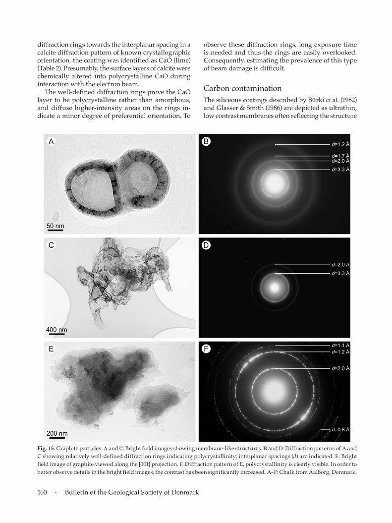
observe these diffraction rings, long exposure time is needed and thus the rings are easily overlooked. Consequently, estimating the prevalence of this type of beam damage is difficult.
Carbon contaminationThe siliceous coatings described by Bürki et al. (1982) and Glasser & Smith (1986) are depicted as ultrathin, low contrast membranes often reflecting the structure
diffraction rings towards the interplanar spacing in a calcite diffraction pattern of known crystallographic orientation, the coating was identified as CaO (lime) (Table 2). Presumably, the surface layers of calcite were chemically altered into polycrystalline CaO during interaction with the electron beam.
The well-defined diffraction rings prove the CaO layer to be polycrystalline rather than amorphous, and diffuse higher-intensity areas on the rings in-dicate a minor degree of preferential orientation. To
Fig. 15. Graphite particles. A and C: Bright field images showing membrane-like structures. B and D: Diffraction patterns of A and C showing relatively well-defined diffraction rings indicating polycrystallinity; interplanar spacings (d) are indicated. E: Bright field image of graphite viewed along the [001] projection. F: Diffraction pattern of E, polycrystallinity is clearly visible. In order to better observe details in the bright field images, the contrast has been significantly increased. A–F: Chalk from Aalborg, Denmark.

Challenges related to studies of chalk particle surfaces in SEM and TEM · 161
observations fit well with the dissolution-precipitation theory presented by Heggheim et al. (2005) and dis-cussed further by Strand et al. (2007).
However, during tilting of the stage it became clear that this cementation phenomenon was an optical il-lusion created by one particle partly covering another (Fig. 17A). As coverage was increased during tilting of the stage, the apparent line of coalescence grew longer and the meniscus-like cement was pushed outwards
of coccoliths (Glasser & Smith 1986, figs 11.2, 11.4a). In the present study, similar membrane-like structures were frequently observed scattered on TEM carbon films. These membranes are ultrathin, probably just a few nanometres, and irregularly shaped with sizes ranging from less than 100 nm to more than 5 μm (Fig. 15A and C). Size and shape of the membranes are difficult to determine due to their crumpled ap-pearance, and none of the observed examples reflect coccolith morphology. The membranes produce fairly well-defined diffraction rings suggesting the coatings to be polycrystalline rather than amorphous (Fig. 15B and D). The diffraction planes with a d spacing of 3.6 Å and 1.8 Å, respectively, normally show some degree of preferential orientation (Fig. 15B and D). Initially, we thought that these membranes were siliceous coatings as described by Bürki et al. (1982) and Glasser & Smith (1986). The interplanar spacing of diffraction planes observed in Fig. 15B and D, however, did not corre-spond to those of silica. Ultimately the membranes were found to consist of graphite, as evidenced from comparison of observed diffraction data with graphite diffraction data (Table 3). It is thus possible that the membranes of this study and the coatings of Bürki et al. (1982) and Glasser & Smith (1986) are separate phenomena.
Occasionally more crystallographically mature versions of membranes are found (Fig. 15E) with dif-fraction patterns corresponding to the [001] projection of graphite (Fig. 15F). Possibly, this graphite originates from the carbon film supporting the chalk sample.
Apparent cohesion between calcite particlesIn order to understand and describe the mechanical strength of chalk, the cementation features related to particle contacts were investigated in TEM, but interpretation of contact points between calcite parti-cles should be approached cautiously. Fig. 16A shows two calcite particles from a suspension sample; the particles are apparently grown together along a line bounded by meniscus-like cement (Fig. 16B). These
Table 3. Interplanar spacings (d) of observed membranes and graphite
Observed membranesd spacing (Å)
Graphited spacing (Å)
Graphite Relative intensity
hkl
3.3 3.3553 100.0 002
2.1319 3.5 100
2.0 2.0318 16.7 101
1.7994 3.0 102
1.7 1.6777 5.4 004
1.5433 4.5 103
1.3184 0.7 104
1.2 1.2309 5.0 110
1.1556 7.3 112
1.1358 1.0 105
1.1184 0.7 006
1.1 1.0659 0.1 200
1.0527 1.0 201
1.0159 0.3 202
0.9924 4.1 114
0.9904 2.0 106
0.9623 0.8 203
0.8997 0.2 204
0.8743 0.4 107
0.8388 0.3 008
0.8347 0.6 205
0.8277 2.7 116
0.8 0.8058 0.3 210
0.8000 1.5 211
0.7835 0.5 212
Diffraction data for graphite are cited from Howe et al. (2003).
Fig. 16. Apparent cohesion. A: Two calcite particles apparently in con-tact with each other. B: Close-up of the contact area. The particles seem to have grown together along a line flanked with meniscus-like cement.

162 · Bulletin of the Geological Society of Denmark
in contact originally but this fact may remain hidden during stage tilting as the particles will seem to be in contact visually at all times.
Residual adhesive in ion-milled samplesHighly porous and weakly consolidated chalk is a challenging material when it comes to preparing samples of limited thickness, e.g. ion-milled samples. Thinning of such chalk by ion-milling requires stabi-lisation of the chalk structure by saturating the pore space with a soluble adhesive. After finishing the thin-ning process, the slice of chalk is cleaned by adding a solvent removing the adhesive. However, traces of adhesive will probably always be left behind, and to avoid charging, a thin carbon film is applied to the chalk sample. This can lead to a false interpretation of two calcite particles being cemented together (Fig. 18).
Consequences of misinterpretationsErroneous characterisation of particle surface chem-istry may result in wrong assessment of wettability and how wettability may be modified to increase oil recovery. Thus, correct detection of coatings and other substances a few nanometres thick attached to particle surfaces, and determining the extent of such matters, are important tasks in attempts to increase oil recovery. This study has pointed out several cases where sample preparation and instrument settings of SEM and TEM are responsible for creating, hiding, altering or preventing identification of structures re-lated to chalk particle surfaces and particle contacts.
(Fig. 17B). Reversing the tilt angle reduced the contact area between the two particles correspondingly (Fig. 17C), and ultimately it became probable that what we saw was two separate particles settled next to each other during sample preparation.
By tilting the stage it may be possible to visually separate two calcite particles apparently in contact. However, revealing truly intergrown calcite particles visually poses significant difficulties; irregularly shaped interfingering particles may not have been
Fig. 17. Apparent cohesion. The upper row of drawings represents lateral views of the particles; the lower row shows the particles as observed in the microscope, i.e. from above. A: Slight overlap, the particles seem to have grown together. B: Tilting the sample +30 increases the overlap; the particles seem intimately intergrown. C: Tilting the sample –30 decreases the overlap; the particles appear to be loosely connected.
Fig. 18. Ion-milled chalk sample. The meniscus-like structure situated between two calcite particles may be interpreted as cementation but is more likely constituted by residual adhe-sive from the thinning process or carbon from the conductive carbon film.
Challenges related to studies of chalk particle surfaces in SEM and TEM · 163
Normally, chalk is cleaned for salt and drilling mud before it is subjected to various analyses. However, sometimes evaporating pore water leaves some salt behind in the chalk, which may affect the outcome of e.g. X-ray diffraction analysis (XRD) and conventional core analysis (porosity and permeability).
TEM. Beam damage (Fig. 14, Table 2) may not only change the mineralogy of the particle surface layers, but possibly also the particle properties. This may have an effect on wettability.
Hidden surfaces SEM. The thin carbon coatings derived from the carbon adhesive disc (Figs 1–2), and also the applied conductive metal coatings (Figs 3–6), may mask the true nature of the particle surfaces, depending on the type and thickness of the coating. Important in-formation regarding surface mineralogy may remain undetected and result in erroneous characterisation of the surface properties of the particle.
Undetected substances adhering to the particle surfaceSEM. The effect of high acceleration voltage is loss of surface detail (Fig. 9A, C) and thus loss of information on ultrathin substances adhering to the particle sur-face, as seen in Fig. 9B, D. That ultrathin flakes adher-ing to calcite may be clay was proposed by Skovbjerg et al. (2012), who also demonstrated intermediate wettability of the flakes. This finding suggests that barely detectable clay particles may play a major wettability-controlling role and thus emphasises the importance of careful analysis of particle surfaces. However, it still remains unresolved whether these flakes before removal of the pore fluids were adher-ing to the particle surface or were suspended in the pore fluids.
Apparent contact cement between chalk particlesSEM. When conductive metal coatings are applied to chalk in thicknesses of 40 nm or more, submicron-sized details become blurred and indistinct and attain a false robustness (Fig. 5). The contact cementation between chalk particles may appear more well-devel-oped than it really is, which may lead to overestima-tion of chalk consolidation and mechanical strength.
TEM. The visual challenges related to identifica-tion of particle contacts in TEM (Figs 16–17) as well as identification of residual adhesive (Fig. 18) may
Artificial surface coatings SEM. Carbon from the carbon adhesive disc may spread to and cover calcite particles with a uniform, few nanometres thick coating (Figs 1–2) that should not be confused with any original organic coatings and seen as an indicator of oil wettability. Conductive metal coatings applied to the chalk particle surface may change the appearance of the surface texture depending on type and thickness of the coating (Figs 3–5).
TEM. Ultrathin graphite membranes (Fig. 15), pos-sibly originating from the sample holder, should not be mistaken for organic coatings originally covering the particles with the implication this would have for chalk surface properties.
Artificial surface substances and appearancesSEM. Electron-induced sample alteration may have implications for illite filaments, which will curl into tiny spirals when hit by electrons (Fig. 10). As illite commonly is associated with smectite in mixed-layer structures (e.g. Lindgreen et al. 2002), the erroneous conclusion may be drawn that the curling phenom-enon is due to smectite loosing water and transform-ing into illite. This, however, requires that a sufficient amount of potassium ions is available for the illite structure from the pore fluid, which necessarily has to be water as oil is incapable of transporting ions. The transformation from smectite to illite is used as an indicator of maximum burial depth, and wrong determination of the smectite–illite transition may lead to wrong assessments of maximum burial depth.
Recent organic filaments in chalk (Fig. 11) are easily identified, but the clay-like flattened terminations of the filaments may deceive as they often cover large parts of the chalk particle surfaces and thus give the impression that clay plays a major role in the particle surface–pore fluid interaction.
Whether authigenic non-carbonates, typically clays or submicron-sized quartz, were originally suspended in the pore fluid or attached to or covering the chalk particle surface is difficult to affirm. If the non-carbonates originally stuck to the particle sur-faces, they would determine the interaction between particle and pore fluid. In order to investigate original positions of non-carbonates in chalk, a cryo (freez-ing) SEM should be employed. Original pore fluids must remain in place during and after sampling and sample preparation. In the frozen sample, suspended constituents remain suspended and fixed in the pore fluid and may be observed in situ.

164 · Bulletin of the Geological Society of Denmark
During TEM investigations of chalk, attention should be paid to the following phenomena:1. The high acceleration voltage necessary to transmit
electrons through calcite particles may damage the crystal structure and cause gradual amorphisation. A thin CaO coating is interpreted as a mineralogical change from CaCO3 to CaO (lime) caused by beam damage restricted to the calcite surface.
2. Ultrathin membranes sharing similarities with si-liceous coatings described in earlier literature may be graphite, possibly derived from the carbon film supporting the chalk sample.
3. Calcite particles overlapping each other in suspen-sion samples may seem to be cemented together but may in fact be separate particles settled next to each other during sample preparation.
4. Residual adhesive from the ion milling process or applied conductive carbon film should not be con-fused with cementation.
AcknowledgementsThe Research Council of Norway and BP Norway are gratefully acknowledged for financial support. Several persons have directly or indirectly been involved in this study via discussions and technical assistance and we want to thank them all. From the University of Oslo, we especially want to thank Professor Johan Taftø for beneficial discussions and assistance in interpreting polycrystalline and amorphous material observed in TEM. Ingunn Cecilie Oddsen and Ola Risvik from the University of Stavanger are thanked for technical assistance during SEM investigations. Jørgen Bilde-Sørensen from Risø National Laboratory is acknowl-edged for technical and interpretational assistance related to TEM investigations. Emil Makovicky from the University of Copenhagen is acknowledged for providing important insight into some of the problems described. Finally, the manuscript was improved by the constructive comments of the referees.
ReferencesAustad, T. & Standnes, D.C. 2003: Spontaneous imbibition of
water into oil-wet carbonates. Journal of Petroleum Science and Engineering 39, 363–376.
Bürki, P.M., Glasser, L.S.D. & Smith, D.N. 1982: Surface coatings on ancient coccoliths. Nature 297, 145–147.
Fabricius, I.L. 2007: Chalk: composition, diagenesis and physi-cal properties. Bulletin of the Geological Society of Denmark 55, 97–128.
result in overestimation of the degree of cementa-tion between particles and the mechanical strength of the chalk.
ConclusionsSEM and TEM investigation of chalk at high magnifica-tion provides detailed information on the morphology, size and mineralogy of chalk particles, and structural features including cementation and spatial distribution of non-carbonate minerals can be visualised. However, the ability to resolve fine details also exposes mor-phological and structural changes caused by sample preparation and interaction between sample and elec-tron beam. Misinterpretation of features as described in this study may lead to inaccurate characterisation of the surfaces of chalk particles and untenable con-clusions with regard to their properties. As a possible consequence, wettability, mechanical strength and maximum burial depth of a chalk reservoir may be evaluated wrongly.
For SEM investigations of chalk, microscopists are encouraged to pay attention to the following phe-nomena.1. Conductive coatings may produce artificial sur-
face textures and artificial ornaments, which may mask genuine surface details. To minimise these effects, coating application time should be kept at a minimum.
2. Chalk particles and small chalk aggregates mounted on carbon adhesive discs may submerge into the carbon substrate, or their surfaces may be covered by an ultrathin film of creeping carbon.
3. Acceleration voltage determines the probing depth of the electron beam and thus the amount of observ-able detail. By lowering the acceleration voltage, an apparently smooth surface may reveal significant ornamentation.
4. High-energy electrons hitting delicate particles may cause the particle shape to change. For example, submicron-sized thin clay flakes tend to bend or curl when hit by electrons.
5. Flattened terminations of organic filaments attached to calcite particle surfaces mimic clay flakes.
6. Authigenic non-carbonate minerals attached to the calcite surface may have resided suspended in pore fluids and settled when the fluids were removed during sampling or sample preparation.
7. Removal of pore fluids by drying may cause sus-pended ions to concentrate and precipitate. The occurrence of salt crystals indicates the original presence of brine.

Challenges related to studies of chalk particle surfaces in SEM and TEM · 165
ricius, I.L. 2018: Elasticity and electrical resistivity of chalk and greensand during water flooding with selective ions. Petroleum Science and Engineering 161, 204–218.
Larsen, J.K. & Fabricius, I.L. 2004: Interpretation of water satu-ration above the transitional zone in chalk reservoirs. SPE Reservoir Evaluation and Engineering 7, 155–163.
Lindgreen, H., Drits, V.A., Sakharov, B.A., Jakobsen, H.J., Salyn, A.L., Dainyak, L.G. & Krøyer, H. 2002: The structure and diagenetic transformation of illite-smectite and chlorite-smectite from North Sea Cretaceous–Tertiary chalk. Clay Minerals 37, 429–450.
Nermoen, A., Korsnes, R.I., Storm, E.V., Stødle, T. Madland, M.V. & Fabricius, I.L. 2018: Incorporating electrostatic ef-fects into the effective stress relation – insights from chalk experiments. Geophysics 83, 1–62.
Risnes, R. & Flaageng, O. 1999: Mechanical Properties of Chalk with Emphasis on Chalk-Fluid Interactions and Microme-chanical Aspects. Oil & Gas Science and Technology – Revue de l’Institut Français du Pétrole 54(6), 751–758.
Røgen, B. & Fabricius, I.L. 2002: Influence of clay and silica on permeability and capillary entry pressure of chalk reservoirs in the North Sea. Petroleum Geoscience 8, 287–293.
Røgen, B., Fabricius, I.L. & Gommesen, L. 1999: Chalk Rock Catalogue: Joint Chalk Research Phase V, Project 4 (text vol.+Appendix). Technical University of Denmark, Copen-hagen, 94+130 pp.
Skinner, A.J., LaFemina, J.P. & Jansen, H.J.F. 1994: Structure and bonding of calcite: A theoretical study. American Mineralo-gist 79, 205–214.
Skovbjerg, L., Hassenkam, T., Makovicky, E., Hem, C.P., Yang, M., Bovet, N.E. & Stipp, S.L.S. 2012: Nano sized clay detected on chalk particle surfaces. Geochimica et Cosmochimica Acta 99, 57–70.
Stipp, S.L.S. 1999: Toward a conceptual model of the calcite surface: Hydration, hydrolysis, and surface potential. Geo-chimica et Cosmochimica Acta 63, 3121–3131.
Strand, S., Hjuler, M.L., Torsvik, R., Pedersen, J.I., Madland, M.V. & Austad, T. 2007: Wettability of chalk: Impact of silica, clay content, and mechanical properties. Petroleum Geosci-ence 13, 69–80.
Williams, D.B. & Carter, C.B. 2009: Transmission Electron Microscopy: A Textbook for Materials Science. 760 pp., 2nd. edition. Springer, New York.
Fiquet, G., Richet, P. & Montagnac, G. 1999: High-temperature thermal expansion of lime, periclase, corundum and spinel. Physics and Chemistry of Minerals 27, 103–111.
Folk, R.L. & Lynch, F.L. 2001: Organic matter, putative nan-nobacteria and the formation of ooids and hardgrounds. Sedimentology 48, 215–229.
Generosi, J., Ceccato, M., Andersson, M.P., Hassenkam, T., Dobberschütz, S., Bovet, N.E. & Stipp, S.L.S. 2017: Calcite wettability in the presence of dissolved Mg2+ and SO4
2-. Energy & Fuels 31(1), 1005–1014.
Glasser, L.S.D. & Smith, D.N. 1986: Siliceous coatings on fos-sil coccoliths – how did they arise? In: Sieveking, G.D.G. & Hart, M.B. (eds), The Scientific Study of Flint and Chert. Proceedings of the Fourth International Flint Symposium held at Brighton Polytechnic 10–15 April 1983, 105–109. Cambridge: Cambridge University Press.
Goldstein, J., Newbury, D., Joy, D., Lyman, C., Echlin, P., Lif-shin, E., Sawyer, L. & Michael, J. 2003: Scanning Electron Microscopy and X-Ray Microanalysis. Kluwer Academic/Plenum Publishers, New York, 689 pp.
Goodhew, P.J., Humphreys, J. & Beanland, R. 2001: Electron microscopy and analysis. Taylor & Francis, London, 251 pp.
Heggheim, T., Madland, M.V., Risnes, R. & Austad, T. 2005: A chemical induced enhanced weakening of chalk by seawater. Journal of Petroleum Science and Engineering 46, 171–184.
Henriksen, K., Young, J.R., Bown, P.R. & Stipp, S.L.S. 2004: Coccolith biomineralisation studied with atomic force microscopy. Palaeontology 47(3), 725–743.
Hjuler, M.L. & Fabricius, I.L. 2009: Engineering properties of chalk related to diagenetic variations of Upper Cretaceous onshore and offshore chalk in the North Sea area. Journal of Petroleum Science and Engineering 68, 151–170.
Howe, J.Y., Rawn, C.J., Jones, L.E. & Ow, H. 2003: Improved crystallographic data for graphite. Powder Diffraction 18(2), 150–154.
Katika, K., Addassi, M., Alam, M.M. & Fabricius, I.L. 2015: The effect of divalent ions on the elasticity and pore collapse of chalk evaluated from compressional wave velocity and low-field Nuclear Magnetic Resonance (NMR). Petroleum Science and Engineering 136, 88–99.
Katika, K., Alam, M.M., Alexeev, A., Chakravarty, K.H., Fosbøl, P.L., Revil, A., Stenby, E., Xiarchos, I., Yousefi, A. & Fab-