INTERPHASE PC/VIEW/180 - Beam Reach€¦ · · 2005-08-24INTERPHASE PC/VIEW/180 ... 200 kHz...
68
INTERPHASE INTERPHASE PC/VIEW/180 ™ OPERATION MANUAL
Transcript of INTERPHASE PC/VIEW/180 - Beam Reach€¦ · · 2005-08-24INTERPHASE PC/VIEW/180 ... 200 kHz...
INTERPHASEINTERPHASEPC/VIEW/180™
OPERATION
MANUAL

2
To Our Customer:
Thank you for choosing the Interphase PC/View or PC/180 Forward Scanning Sonar.Throughout the development of this fine product, we have been primarily concerned withcreating a unit that offers the best possible value for your money. Selection of features,ease of use, superior performance and outstanding reliability were the benchmarks uponwhich all important design decisions were made. We are proud of the PC/180 ForwardScanning Sonar and your satisfaction is very important to us. We welcome any commentsor suggestions that you might have about this equipment. You can reach us by phone at:831-477-4944, fax at: 831-462-7444, or by e-mail at [email protected]
It is very important that you complete and return the WARRANTY REGISTRATIONCARD within 15 days of purchase so that your unit may be protected under the warranty.
Thank You Again,
INTERPHASE TECHNOLOGIES, INC.
©2004 Interphase Technologies, Inc.
Interphase PC/View™ and PC/180™ are trademarks of Interphase Technologies, Inc.Other brands or products are the trademarks or registered trademarks of their respective holders andshould be treated as such.
Publication # = PC/View/180 1.0 030430 (P/N 25-4011-

3
1 Introduction 6General Information 6Warranty Information 6Unpacking and Inspection 7
2 Installing PC/180 8Transducer Installation 9
The Transducers 9Forward Direction 10Selecting the Best Location 10Using the Fairing Blocks 11Thru-hull Mounting 13
Acoustic Interface Module Installation 13
3 Installing PC/View 14Transducer Installation 14
General Considerations 15Transom Transducer Installation 16
Selecting a Location 16Attaching the Bracket 16Mounting the Transducer 17Forward Direction of the Transducer 18
Thru-Hull Transducer Installation 18Selecting a Location 18Using a Fairing Block 19Thru-Hull Mounting 20
Acoustic Interface Module 21
4 Software Installation 22
5 Quick Start 24Running PC/View/180 24Defaults 25Demo Mode 25Beam Width 25
Contents

4
6 Basic Operation 26Getting Started 26
The Toolbar 26The Status Bar 26
Operating Modes 27Demo Mode 27Real-Time Mode 27
Setting System Parameters 28Parallel Port Address 28Transducer Mount Corrections 28
Level Adjustment 28PC/180 Align Adjustment 28PC/180 Keel Offset 29PC/View Alignment Adjustment 30PC/View Keel Offset 30
Displays 30Setting Color and Units 32VERT: Vertical Scan Display 32HORZ180: Horizontal Scan Display 33PC/View HORZ: Horizontal Scan Display 33DOWN: Downlooker Display 34VSPLIT: Vertical Split-Screen Display 34HSPLIT180: Horizontal Split-Screen Display 35PC/View Horizontal Split-Screen Display 35Depth Window 35
Adjusting the Gain and Range 36Gain Adjustment 36Range Adjustment 37
Using the Alarm 38Adjusting the Viewing Area 38
Sector Width and Steer 38Scan Mode and Method 39
Vertical Scan 39Horizontal Scan 40
Zoom 40Adjusting the Depth Tracker 41
Surface Masking 41Threshold 41
Saving Data with Screen Capture 43
5
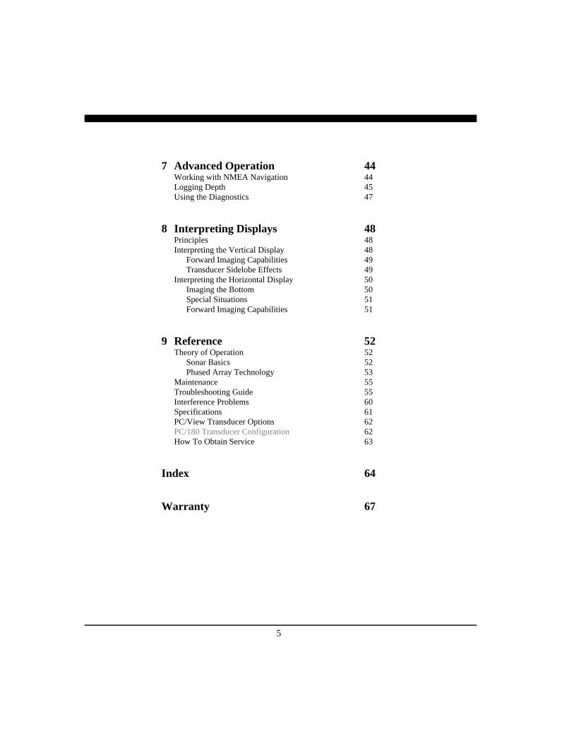
7 Advanced Operation 44Working with NMEA Navigation 44Logging Depth 45Using the Diagnostics 47
8 Interpreting Displays 48Principles 48Interpreting the Vertical Display 48
Forward Imaging Capabilities 49Transducer Sidelobe Effects 49
Interpreting the Horizontal Display 50Imaging the Bottom 50Special Situations 51Forward Imaging Capabilities 51
9 Reference 52Theory of Operation 52
Sonar Basics 52Phased Array Technology 53
Maintenance 55Troubleshooting Guide 55Interference Problems 60Specifications 61PC/View Transducer Options 62PC/180 Transducer Configuration 62How To Obtain Service 63
Index 64
Warranty 67

6
General InformationThank you for choosing the Interphase PC/View/180 Dual-Axis Forward Scanning Sonar. The PC/View/180 has been designed to work with your on-board PC and will display water depth, bottom condi-tions, fish and other submerged objects and debris, allon your computer’s high resolution color display.
The PC/180 combines a 90-degree vertical scanningsector with a horizontal scanning sector that coversthe full 180 degrees in front of your vessel. PC/180’stwo-transducer configuration has the added advantageof avoiding any potential acoustic shadowing createdby a deep keel. This is because the port half of thehorizontal scan is accomplished using a transducermounted on the port side of the keel while the star-board half of the horizontal scan is accomplished us-ing a transducer mounted on the starboard side of thekeel.
To insure that you receive the maximum benefitsavailable from the outstanding features of the Inter-phase PC/View/180, this manual includes a detailedguide to the use and interpretation of the system’smodes and displays. An instructive demonstrationmode has been designed into the PC/View/180 tofamiliarize you with the unit’s features. In addition,the Quick Start chapter gives you the necessary infor-mation to get PC/View/180 software up and runningas quickly as possible. Please read the Installationchapter carefully before attempting to install PC/View/180 on your vessel.
Warranty InformationInterphase provides a Limited Warranty on the PC/View/180 Forward Scanning Sonar. Please read thiswarranty (reprinted at the back of this manual) andclosely follow its terms and conditions should yourPC/View/180 require repair. It is highly recom-mended that you save all packing materials so that, in
NAVIGATION WARNINGNautical navigation is a critical element inthe safety and success of each open-waterboating experience and should only beperformed by experienced navigators.
While the PC/View/180 product is a usefulnavigation aid, it should never be reliedupon as the only means of navigation. It isprudent to use more than one proveninstrument and more than one acceptedmethod in support of navigation decisions.
1 Introduction
Award WinningTechnology
For its pioneering work in developingPhased Array Scanning Sonar,Interphase Technologies won theprestigious IMTEC INNOVATIONAWARD.
PC/View & PC/180 ForwardLooking Scanning Sonar is based onthis same award-winning technology.
USING THIS MANUAL
This manual contains operating instructions forboth PC/View and PC/180. While these twoproducts share many features, somefeatures are specific to PC/180 only.Features specific to PC/180 are highlighted inGREY TEXT.
7
the unlikely event that you must return your PC/View/180 for repair, it can be fully protected.
Should you experience a problem with your PC/View/180, first refer to the Troubleshooting section (p. 55) ofthis manual. Most common problems and their solu-tions are described here. If problems persist, call Inter-phase Technical Service at (831) 477-4944. We willbe happy to assist you, and if required, we will giveyou instructions on how to get your unit serviced.
The enclosed warranty registration card must be com-pleted and returned to Interphase within 15 days of pur-chase so that your unit may be protected under the war-ranty. Failure to return the warranty card may causeunnecessary delays in processing your unit for warrantyrepair.
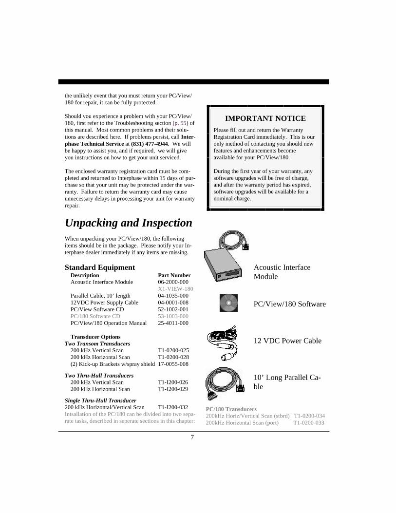
Unpacking and InspectionWhen unpacking your PC/View/180, the followingitems should be in the package. Please notify your In-terphase dealer immediately if any items are missing.
Standard EquipmentDescription Part NumberAcoustic Interface Module 06-2000-000
X1-VIEW-180Parallel Cable, 10’ length 04-1035-00012VDC Power Supply Cable 04-0001-008PC/View Software CD 52-1002-001PC/180 Software CD 53-1003-000PC/View/180 Operation Manual 25-4011-000
Transducer OptionsTwo Transom Transducers
200 kHz Vertical Scan T1-0200-025200 kHz Horizontal Scan T1-0200-028(2) Kick-up Brackets w/spray shield 17-0055-008
Two Thru-Hull Transducers200 kHz Vertical Scan T1-I200-026200 kHz Horizontal Scan T1-I200-029
Single Thru-Hull Transducer200 kHz Horizontal/Vertical Scan T1-I200-032Intsallation of the PC/180 can be divided into two sepa-rate tasks, described in seperate sections in this chapter:
IMPORTANT NOTICEPlease fill out and return the WarrantyRegistration Card immediately. This is ouronly method of contacting you should newfeatures and enhancements becomeavailable for your PC/View/180.
During the first year of your warranty, anysoftware upgrades will be free of charge,and after the warranty period has expired,software upgrades will be available for anominal charge.
Acoustic InterfaceModule
PC/View/180 Software
12 VDC Power Cable
10’ Long Parallel Ca-ble
PC/180 Transducers200kHz Horiz/Vertical Scan (stbrd) T1-0200-034200kHz Horizontal Scan (port) T1-0200-033
8
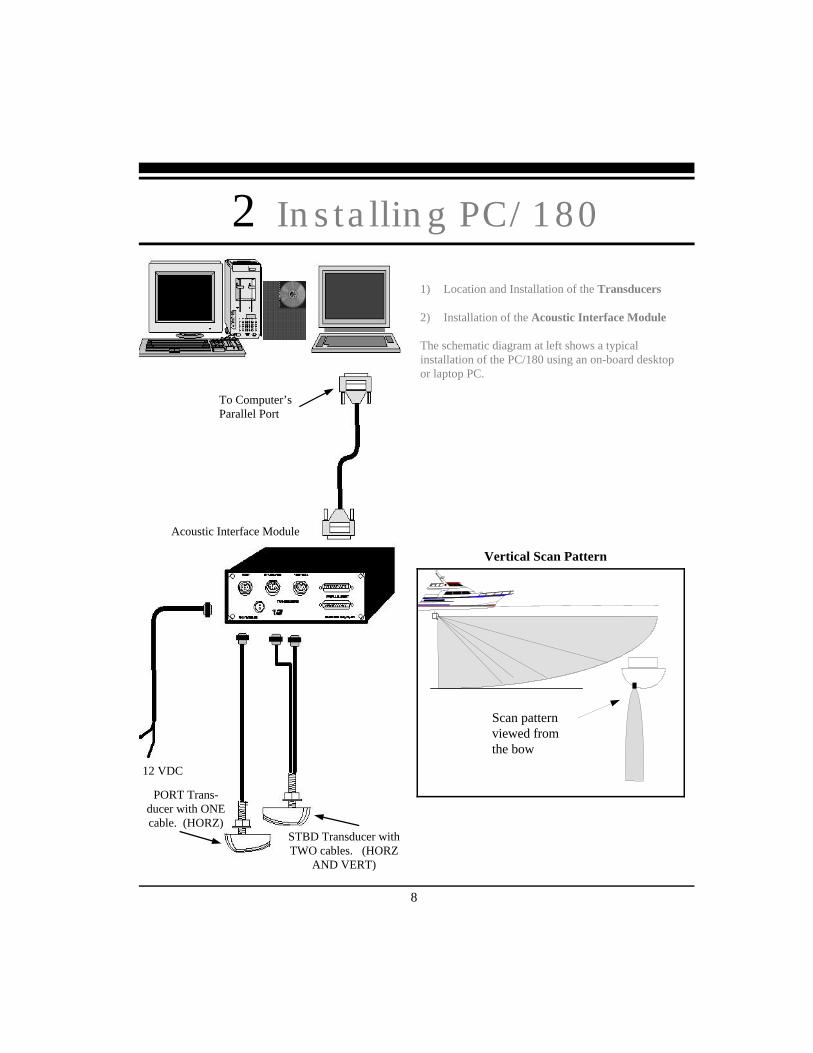
1) Location and Installation of the Transducers
2) Installation of the Acoustic Interface Module
The schematic diagram at left shows a typicalinstallation of the PC/180 using an on-board desktopor laptop PC.
2 Installing PC/180
Vertical Scan Pattern
Scan patternviewed fromthe bow
To Computer’sParallel Port
12 VDC
PORT Trans-ducer with ONEcable. (HORZ)
STBD Transducer withTWO cables. (HORZ
AND VERT)
Acoustic Interface Module
9
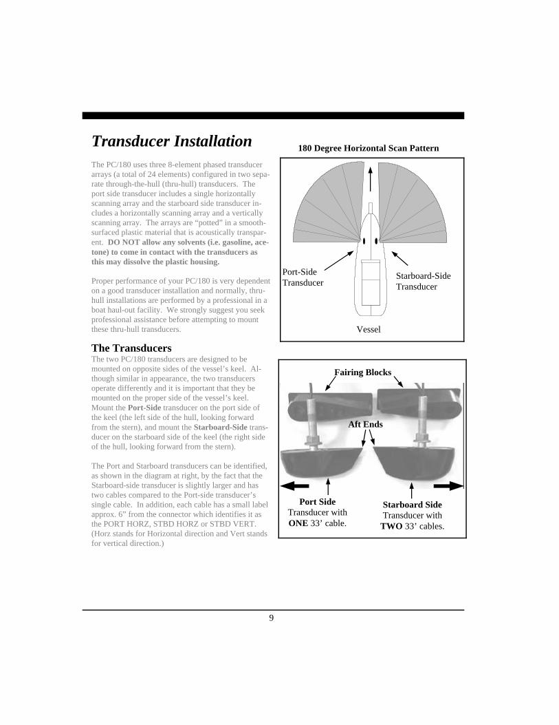
Transducer InstallationThe PC/180 uses three 8-element phased transducerarrays (a total of 24 elements) configured in two sepa-rate through-the-hull (thru-hull) transducers. Theport side transducer includes a single horizontallyscanning array and the starboard side transducer in-cludes a horizontally scanning array and a verticallyscanning array. The arrays are “potted” in a smooth-surfaced plastic material that is acoustically transpar-ent. DO NOT allow any solvents (i.e. gasoline, ace-tone) to come in contact with the transducers asthis may dissolve the plastic housing.
Proper performance of your PC/180 is very dependenton a good transducer installation and normally, thru-hull installations are performed by a professional in aboat haul-out facility. We strongly suggest you seekprofessional assistance before attempting to mountthese thru-hull transducers.
The TransducersThe two PC/180 transducers are designed to bemounted on opposite sides of the vessel’s keel. Al-though similar in appearance, the two transducersoperate differently and it is important that they bemounted on the proper side of the vessel’s keel.Mount the Port-Side transducer on the port side ofthe keel (the left side of the hull, looking forwardfrom the stern), and mount the Starboard-Side trans-ducer on the starboard side of the keel (the right sideof the hull, looking forward from the stern).
The Port and Starboard transducers can be identified,as shown in the diagram at right, by the fact that theStarboard-side transducer is slightly larger and hastwo cables compared to the Port-side transducer’ssingle cable. In addition, each cable has a small labelapprox. 6” from the connector which identifies it asthe PORT HORZ, STBD HORZ or STBD VERT.(Horz stands for Horizontal direction and Vert standsfor vertical direction.)
Port-SideTransducer
Starboard-SideTransducer
180 Degree Horizontal Scan Pattern
Vessel
Starboard SideTransducer with
TWO 33’ cables.
Port SideTransducer withONE 33’ cable.
Aft Ends
Fairing Blocks

10
Forward DirectionThe orientation of the mounted transducers is criticalto the performance of the PC/180. Note that the moreblunt, rounded end of each transducer should bepointed forward. The angled, more narrow endsshould be pointed aft as shown in the figure at left.
Selecting the Best LocationThe best location to mount the thru-hull transducerwill vary with the type of boat. In order to simplifythe installation, attempt to find a location with a smalldead-rise angle.
a. On displacement hulls (sailboats, trawlers, etc.)locate the transducer about 1/3 aft along the wa-terline. Generally this provides the best compro-mise between obtaining aeration-free water andminimizing propeller noise. Water near the bowand near the keel can be quite aerated. Since thePC/180’s transducer can not see through aeratedwater, it is best to mount the transducer midwaybetween these two areas.
b. On planing powerboat hulls, the transducershould be mounted well aft and close to the keelto insure that the transducer is in contact with thewater at higher boat speeds. Unfortunately,mounting the transducers well aft limits the maxi-mum forward range in front of the vessel’s bow.However, the transducers must be in the water towork and if they are mounted too far forward on aplaning hull they will often lose contact with thewater. In this situation, the PC/180 can only beused at slower vessel speeds which do not resultin planing operation.
DO NOT install a bronze transducer housing directlyinto an aluminum or steel hull because electrolyticcorrosion will occur.
Transducer cables will need to be routed to theAcoustic Interface Module. If you need transducercable lengths greater than the standard 30’ length,order three 30’ extension cables (Interphase Part #04-0014-008).
FORWARD
Fairing Block
Transducer
Typical Thru-Hull Transducer Locations
Full Keel Sailboat
Displacement PowerVessel Hull
L = Length of Waterline
~ 1/4 to 1/3
L = Length of Waterline
~ 1/4 to 1/3Transducer
Transducers

11
Using the Fairing BlocksNearly all vessels have some dead-rise angle at thetransducer mounting location. If the thru-hull trans-ducers were mounted directly to the hull, the soundbeam from the transducer would be tilted off the ver-tical at the same angle as the dead-rise and wouldcause errors in the interpretation of the displayed pic-ture. To correct this situation, most thru-hull instal-lations will require the use of fairing blocks to insurethat the transducer is mounted in the proper orienta-tion..
Two custom-molded fairing blocks for the PC/180transducers have been included with your system tomake installation as simple as possible.
Measure the dead-rise angle of the hull at the selectedmounting location and cut the block to a shape thatfits the exact contour of the hull. After cutting thefairing block, trial-fit the block to the hull. The upperpart of the block should be inside the hull and thelower part of the block should be outside the hull toclamp the assembly in place as shown in the diagramat right.
It is very important that the flat top surface of thetransducer be parallel to the water. Because of theequipment and skill required, we suggest that yourprofessional boatyard cut the fairing blocks and in-stall the transducers.
One of two trans-ducer fairing blocksincluded with yourPC/180 system.
Threaded BronzeStem
Boat’s Hull
Fairing Block(bottom)
Transducer Body
Fairing Block(top)

12
Thru-hull MountingTake the following steps to mount each thru-hulltransducer:
1) Drill a 1/8” pilot hole from inside the hull toassure access to tighten the housing nut andclearance for the transducer cables. If there isany hull irregularity near the selected mountinglocation, it may be desirable to drill from theoutside.
2) Use a 1” hole saw and drill the hole from theoutside of the hull. Sand or clean the areaaround the hole, inside and outside to insurethat the sealing compound will adhere properlyto the hull. Select a marine grade bedding/caulking compound and use according to theinstructions.
3) Remove the bronze hex nut from the housingand cables.
4) Uncoil the two transducer cables and threadthem through the hole to the inside of the hull.Apply a 1/8” thick layer of sealant on the up-per flat surface of the bronze housing and fair-ing block (if used).
5) From the outside of the hull, push the cablesand housing into the 1” hole. Twist the hous-ing slightly to squeeze out excess sealant.Carefully confirm that the transducer is aligned so that the blunt rounded end (the front) is pointed directly toward the front of the boat.
6) Install and tighten bronze hex nut (allow forswelling in wooden hulls). Do not over-tighten nut.
7) Remove excess sealant from the outside toassure smooth water flow over the transducer.
8) Route the cables back to the PC/180 AcousticInterface Box. If possible, avoid running thecables alongside of antenna cables or othersensitive wiring.
**WARNING**Do not cut or splice your phased-arraytransducer cables or remove the 9-pinconnectors. Doing so will seriouslydegrade the performance of your PC/180and VOID YOUR WARRANTY.
Tools Required for TransducerInstallation:
♦ Variable speed electric drill with a chuckcapacity of 10 mm (3/8”) or larger.
♦ Hole saw or spade bit 19 mm (1”) fortransom hole to route cable and connector
♦ Chamfer bit or 6 mm (1/4”) drill bit
♦ Drill bit No. 28 or 4 mm (9/64”)
♦ Drill bit 3 mm (7/64”)
♦ Marine bedding/sealing compound
Note: Make sure your tooling is sharp and ofthe correct diameter before proceeding.
WARNINGDO NOT apply tension to the transducercables as this may sever internal connections.
NOTE: If you need longer transducer cablelengths, purchase the optional 30’ extensioncables (Interphase Part #04-0014-008).Three extension cables will be required.

13
WARNINGWood hulls will expand after the boat is put backinto the water. If you have a wood hull, thetransducer should only be hand-tightened untilthe wood fully expands. Otherwise the woodfairing may crack.
WARNINGBe sure to check for leaks when the boat is placedin the water. Allow at least 24 hours afterinstallation for any leak to appear.
IMPORTANT NOTEIf the boat is kept in saltwater it is recommendedthat the transducer be coated with an anti-foulingpaint. USE ONLY WATER BASED ANTI-FOULING PAINT. DO NOT USE KETONE-BASED PAINTS. Ketone-based anti-foulingpaint attacks the plastic transducer material.
Completed InstallationView From Front of Vessel Looking Aft.
Vessel’s Hull
Acoustic InterfaceModule InstallationThe black box that came with your PC/180 is calledthe Acoustic Interface Module (AIM). It houses thetransmitters and receivers that communicate with thetransducers. The AIM must be connected to the par-allel port of the on-board computer, to the transducersand to a 12VDC power source.
1) Select a location to mount the AIM. Keep inmind that the unit must be protected from frommoisture and extreme temperatures. Also, youwill need to route the 10’ parallel cable, thepower cord and transducer cables to the locationthat you choose.
2) Connect the two-pin plug on the end of thepower supply cable to the power supply jack onthe back panel of the AIM. To minimize electri-cal interference, carefully route the power cableso that it does not run parallel to, or close to thetransducer cable, engine, refrigeration, or anyother critical wiring. Connect the red wire to thepositive terminal and the black wire to the nega-tive terminal of your boat’s 12VDC battery.
3) Connect one end of the parallel cable to the con-nector labeled PARALLEL PORT on the backpanel of the AIM. Connect the other end to theparallel port on your computer.
4) Connect the three transducer cables to the match-ing ports on the back panel of the AIM:
Cable label Panel label PORT HORZ PORTSTBD HORZ STARBOARDSTBD VERT VERTICAL
PORT STARBOARD VERTICAL
PARALLEL PORT
12 VDC1 AMP
P/N X1-VIEW-180 Made in Soquel, CA, USA
Power Supply Jack Transducer Connec-Parallel Ports
(use either
Acoustic Interface Module Back Panel
Note: Signals transmitted through adjacentcables can interfere with one another. Routesensitive cables and antennas so that they donot run adjacent to or parallel to one another.

14
3 Installing PC/View
To Computer’sParallel Port
12 VDC
Vertical ScanningTransducer Cable
HorizontalScanning Trans-ducer Cable+/-
12VDC
Acoustic Interface Module
The diagram at left shows a typical installation of thePC/View using an on-board desktop or laptop PC.
In this chapter, the PC/View installation procedureshave been divided into two major sections;
1) Location and Installation of the Transducer(s)
2) Installation of the Acoustic Interface Module
Transducer InstallationThe PC/View can be ordered with one of severaltransducer configurations; two transom mount trans-ducers, two bronze thru-hull transducers, a specialsingle bronze thru-hull transducer, or with no trans-ducer (if you already have an Interphase scanningtransducer installed).
The PC/View uses two 8-element phased transducerarrays (a total of 16 elements). The arrays are“potted” in a smooth-surfaced plastic material that isacoustically transparent. DO NOT allow any sol-vents (i.e. gasoline, acetone) to come in contactwith the transducer(s) as this may dissolve theplastic housing.
In the single thru-hull configuration all 16 elementsare enclosed in a single transducer. For transom-mount applications two transducers are required, eachcontaining an 8-element array. One of the 8-elementarrays is positioned to scan vertically from straightahead to directly below the boat, while the other arrayis positioned to scan forward horizontally from side toside. When the two thru-hull configuration is chosen,each transducer contains an 8-element array. One ispositioned for vertical scanning and the other for hor-izontal scanning.

15
General ConsiderationsThe orientation of the mounted transducer(s) is criti-cal to the performance of the PC/View. The lowerdiagram at right shows the proper orientation for boththe transom-mount and thru-hull transducer(s). Forall three types of transducers, the broader,rounded or blunt side must point forward.
It is also important to think carefully about the loca-tion of the transducer(s) before proceeding. Considerthe following:
1) The transducer(s) should be located where thereis the least amount of acoustic noise, air bubblesor turbulence caused by the boat’s movement.The transducer(s) should not be located near orespecially directly behind the propeller.
2) The transducer(s) must be mounted so that it willbe level with the water’s surface and will not betilted to either side.
3) The transducer(s) must always remain sub-merged, regardless of the speed of the boat.
4) The transducer(s) should not be mounted whereit could be damaged by underwater obstacles orwhen loading the vessel on a trailer.
5) DO NOT locate the transducer(s) in the extremebow of the boat where it will be subject to in-tense turbulence as the boat pounds through thewater.
6) DO NOT locate the transducer(s) directly behindany hull protrusion which will cause the water tobe turbulent when it reaches the transducer(s) orwhich will obstruct the transducer’s forwardlooking view. For displacement-hull power andsail boats, the thru-hull installation is usuallyrequired.
7) Transducer cable(s) will need to be routed to the Acoustic Interface Module. If you need transducer cable lengths greater than the stan- dard 30’ length, order two 30’ extension cables (Interphase Part # 04-0014-008).
Scanning Directions.Vertical Scan modeshown above andHorizontal Scanmode below
Forward
Forward
Thru-Hull Transducer(s)
Transom Mounted Transducer
Side View
Top View
16
**WARNING**Do not cut or splice your phased-arraytransducer cables or remove the 9-pinconnectors. Doing so will seriouslydegrade the performance of your PC/Viewand VOID YOUR WARRANTY.
Tools Required for TransducerInstallation:
♦ Variable speed electric drill with a chuckcapacity of 10 mm (3/8”) or larger.
♦ Hole saw or spade bit 19 mm (7/8”) fortransom hole to route cable and connector
♦ Chamfer bit or 6 mm (1/4”) drill bit
♦ Drill bit No. 28 or 4 mm (9/64”)
♦ Drill bit 3 mm (7/64”)
♦ Marine bedding/sealing compound
Note: Make sure your tooling is sharp and ofthe correct diameter before proceeding.
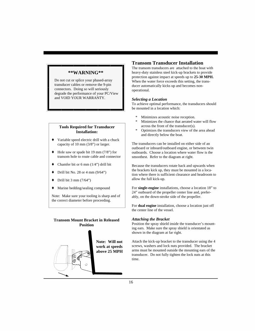
Transom Mount Bracket in ReleasedPosition
Note: Will notwork at speedsabove 25 MPH
Transom Transducer InstallationThe transom transducers are attached to the boat withheavy-duty stainless steel kick-up brackets to provideprotection against impact at speeds up to 25-30 MPH.When the water force exceeds this setting, the trans-ducer automatically kicks up and becomes non-operational.
Selecting a LocationTo achieve optimal performance, the transducers shouldbe mounted in a location which:
* Minimizes acoustic noise reception.* Minimizes the chance that aerated water will flow
across the front of the transducer(s).* Optimizes the transducers view of the area ahead
and directly below the boat.
The transducers can be installed on either side of anoutboard or inboard/outboard engine, or between twinoutboards. Choose a location where water flow is thesmoothest. Refer to the diagram at right.
Because the transducers rotate back and upwards whenthe brackets kick up, they must be mounted in a loca-tion where there is sufficient clearance and headroom toallow the full kick-up.
For single-engine installations, choose a location 18” to24” outboard of the propeller center line and, prefer-ably, on the down-stroke side of the propeller.
For dual engine installation, choose a location just offthe center line of the vessel.
Attaching the BracketPosition the spray shield inside the transducer’s mount-ing ears. Make sure the spray shield is orientated asshown in the diagram at far right.
Attach the kick-up bracket to the transducer using the 4screws, washers and lock nuts provided. The bracketarms must be mounted outside the mounting ears of thetransducer. Do not fully tighten the lock nuts at thistime.
17
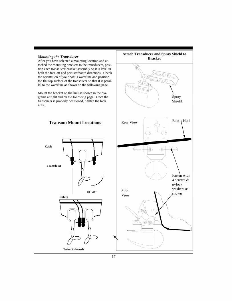
Mounting the TransducerAfter you have selected a mounting location and at-tached the mounting brackets to the transducers, posi-tion each transducer-bracket assembly so it is level inboth the fore-aft and port-starboard directions. Checkthe orientation of your boat’s waterline and positionthe flat top surface of the transducer so that it is paral-lel to the waterline as shown on the following page.
Mount the bracket on the hull as shown in the dia-grams at right and on the following page. Once thetransducer is properly positioned, tighten the locknuts.
18 - 24"
Cables
Twin Outboards
Transducer
Cable
Transom Mount Locations
Attach Transducer and Spray Shield toBracket
Fasten with4 screws &nylockwashers asshown
SideView
Rear View
SprayShield
Boat’s Hull

18
Mount Transducer So it Will Scan Properly
It is important to note that if the vertical scanningtransducer is not mounted so that the fore and aftdirection is parallel to the surface, then the forward-looking display may be distorted where flat bottomsappear to be slanted upwards or downwards. Aftermounting the transducer and actually using the PC/View on the water, you may need to readjust thetransducers' mounting for optimum performance.
Refer to the discussion of Transducer Mount Cor-rections on page 28-30.
NOTEThe flat top of the transducer must be parallelto the water line. This will not necessarily beparallel to the boat’s hull.
Waterline
Transducermust bemountedvertically
RearView
Sideview Waterline
Flat area on top oftransducer must belevel with waterline
Thru-Hull Transducer InstallationThe thru-hull transducer is the recommended choice forlarger boats with in-board engines. Thru-hull mountingis usually required on larger power and sail craft in or-der to find a mounting location free of forward-lookinghull obstructions. PC/View must have a clear viewahead, as it can not see through obstructions such as thevessel’s hull. Please read the following carefully beforestarting the thru-hull installation. Normally, thru-hullinstallations are performed by a professional in a boathaul-out facility and we recommend that you seek pro-fessional assistance before attempting to mount thistransducer.
Selecting a LocationThe best location to mount the thru-hull transducer willvary with the type of boat. Try to find a location withthe smallest dead rise angle.
a. On displacement hulls (sailboats, trawlers, etc.)locate the transducer about 1/3 aft along the water-line. Generally this provides the best compromisebetween obtaining aeration-free water and minimiz-ing propeller noise. Water near the bow and nearthe keel can be quite aerated. Since the transducercan not see through aerated water, it is best to mountthe transducer between these two areas.
b. On sailboats, the transducer should be mountedwhere the acoustic beam will not be shaded by thekeel. A spot forward of a fin keel is usually best.
c. On planing powerboat hulls, the transducer shouldbe mounted well aft and close to the keel to insurethat the transducer is in contact with the water athigher boat speeds.
On inboard/outboard boats, transducer mounting close to the engine usually yields good results. On inboards always mount the transducer well ahead of the propeller(s). Turbulence from props can seriously degrade performance.
d. Mount the transducer on the side of the hull where the propeller is moving downwards. The upward motion of the propeller generates pressure waves and pushes bubbles up against the hull.
Rounded End Forward

19
Suggested Thru-HullTransducer Locations
Fin Keel
Planing Hull
Displacement Hull
IMPORTANT:1) Make sure the water flow across the thru-hull
transducer is free of bubbles and turbulence at allspeeds if good performance is to be achieved.
2) Make sure the transducer has an unobstructed viewof the water ahead and below the boat.
3) On displacement-hull power boats, the transducershould be mounted relatively close to the centerline of the hull.
4) Mount the transducer in a place which has reason-able access from inside the vessel since the trans-ducer’s bronze nut will require tightening frominside the hull.
The transducer must be mounted so that it’s bronzestem is as perpendicular to the water line as possible.If necessary, use a fairing block to properly position thetransducer.
Using a Fairing BlockNearly all vessels have some dead-rise angle at thetransducer mounting location. If the thru-hull trans-ducer were mounted directly to the hull, the soundbeam would be tilted off the vertical at the same angleas the dead-rise. Most thru-hull installations will re-quire a fairing block to insure the transducer is mountedproperly.
A fairing block is typically made of teak, mahogany, orplastic and should be glued between the transducer andthe hull (both inside and outside) to provide a levelmounting surface for the transducer and retaining nut.Make the block as smooth as possible, and not biggerthan the tranducer’s face, to minimize turbulence.
IMPORTANT: After cutting the fairing block, trial-fitit to the hull. The flat top surface of the transducermust be parallel to the water surface.
If you’re installation requires a fairing block, eitherhave one made locally, or purchase a molded plasticunit from Interphase or your Interphase distributor.
For the single thru-hull transducer, the molded Fair-
ing Block Part Number is: 42-2005-000

20
Thru-hull Transducer MountingTake the following steps to mount the thru-hull:
1) Drill a 1/8” pilot hole from inside the hull toassure access to tighten the housing nut andclearance for the transducer cables. If there isany hull irregularity near the selected mountinglocation, it may be desirable to drill from theoutside.
2) Using a 1-1/16” hole saw, drill the hole fromthe outside of the hull. Sand or clean the areaaround the hole, inside and outside to insurethat the sealing compound will adhere properlyto the hull. Select a marine grade bedding/caulking compound and use according to theinstructions.
3) Remove the bronze hex nut from the housingand cables.
4) Uncoil the two transducer cables and threadthem through the hole to the inside of the hull.
Apply a 1/8” thick layer of sealant on the upper flat surface of the bronze housing and fairing block (if used).
5) From the outside of the hull, push the cablesand housing into the 1” hole. Twist the hous-ing slightly to squeeze out excess sealant.Carefully confirm that the transducer is aligned so that the blunt rounded end (the front) is pointed directly toward the front of the boat.
6) Install and tighten bronze hex nut (allow forswelling in wooden hulls). Do not over-tighten nut - especially if a wooden fairingblock is used as it will expand in water.
7) Remove excess sealant from the outside to assure smooth water flow over the transducer.
WARNING
DO NOT apply tension to the transducer cablesas this may sever internal connections.
Hull
Hull
Waterline
Waterline
Keep parallelto waterline !
Keep parallelto waterline !
ForwardTransducer
Mount the Transducer so it is Vertical
Make Sure “Blunt Side” of Transducer isPointed Forward
Side View
Top View
ForwardDirection

21
WARNINGDO NOT install a bronze transducer housingdirectly into an aluminum or steel hull becauseelectrolytic corrosion will occur.
WARNINGWood hulls and fairing blocks will expand afterthe boat is put back into the water, so it isimportant that the transducer be only hand-tightened until the wood fully expands.Otherwise the wood fairing block may crack.
Transducer
Wood orPlasticFairingBlock (Addsealingcompoundbetweenfaring block& hull).
Boat’sHull
Bronze Nut
IMPORTANT NOTEIf the boat is kept in saltwater it isrecommended that the transducer be coatedwith an anti-fouling paint. USE ONLYWATER BASED ANTI-FOULING PAINT.DO NOT USE KETONE-BASED PAINTS.Ketone-based anti-fouling paint will attack theplastic materials used in the transducer.
Acoustic InterfaceModule InstallationThe black box that came with your PC/View iscalled the Acoustic Interface Module (AIM). Ithouses the transmitters and receivers that communi-cate with the transducers. The AIM must be con-nected to the parallel port of the computer, to thetransducers and to a source of 12 VDC power.
1) Select a location to mount the AIM. Keep inmind that the unit must be protected from frommoisture and extreme temperatures. Also, youwill need to route the 10’ computer parallelcable, the power cord and transducer cables tothe location that you choose.
2) Connect the two-pin plug on the end of thepower supply cable to the power supply jackon the back panel of the AIM. Connect the redwire to the positive terminal and the black wireto the negative terminal of your boat’s 12 VDCbattery.
3) Connect one end of the parallel cable to theconnector labeled PARALLEL PORT on theback panel of the AIM. Connect the other endof the parallel cable to the parallel port on yourcomputer.
4) Connect the two transducer cables to thematching ports on the back panel of the AIM:
Cable label Panel label HORZ HORIZONTAL TRANSDUCER
VERT VERTICAL TRANSDUCER
Power Supply Jack
Transducer ConnectorsParallel Ports
(use either one)
Acoustic Interface Module Back Panel
PARALLEL PORT12 VDC1 AMP
P/N X1-VIEW-WIN made in Santa Cruz, CA, USA
HORIZONTALTRANSDUCER
VERTICALTRANSDUCER
22
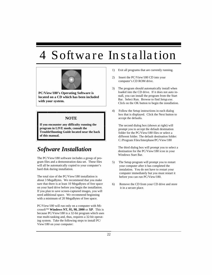
PC/View/180’s Operating Software islocated on a CD which has been includedwith your system.
NOTEIf you encounter any difficulty running theprogram in LIVE mode, consult theTroubleShooting Guide located near the backof this manual.
Software InstallationThe PC/View/180 software includes a group of pro-gram files and a demonstration data set. These fileswill all be automatically copied to your computer’shard disk during installation.
The total size of the PC/View/180 installation isabout 3 MegaBytes. We recommend that you makesure that there is at least 10 MegaBytes of free spaceon your hard drive before you begin the installation.If you plan to save screen-captured images, you willneed additional space. We recommend beginningwith a minimum of 20 MegaBytes of free space.
PC/View/180 will run only on a computer with Mi-crosoft™ Windows NT, 95, 98, 2000 or XP. This isbecause PC/View/180 is a 32-bit program which usestrue multi-tasking and, thus, requires a 32-bit operat-ing system. Take the following steps to install PC/View/180 on your computer:
1) Exit all programs that are currently running.
2) Insert the PC/View/180 CD into your computer’s CD ROM drive.
3) The program should automatically install whenloaded into the CD drive. If it does not auto in-stall, you can install the program from the StartBar. Select Run. Browse to find Setup.exe.Click on the OK button to begin the installation.
4) Follow the Setup instructions in each dialog box that is displayed. Click the Next button to accept the defaults.
The second dialog box (shown at right) will prompt you to accept the default destination folder for the PC/View/180 files or select a different folder. The default destination folder: C:/Program Files/Interphase/PC/View/180
The third dialog box will prompt you to select adestination for the PC/View/180 icon in yourWindows Start Bar.
5) The Setup program will prompt you to restart your computer after it has completed the instalation. You do not have to restart your computer immediately but you must restart it before you can run PC/View/180.
6) Remove the CD from your CD drive and store it in a secure place.
4 Software Installation

23

24
5 Quick Start
Parameter Menu Default Type
Auto-Screen Capture File Off Hard
Color Setup Normal Soft
Units Setup Feet Soft
Surface Masking Setup Off Hard
Depth Threshold Setup Normal Hard
Auto Gain Adjust Off Hard
Gain Adjust 32 Soft
Auto Range Adjust Off Hard
Range Adjust 25 Feet Soft
Alarm Adjust Off Hard
Sector Width Adjust 180 Degrees Soft
Sector Steer Adjust 90 Degrees Soft
Scan Mode Adjust Normal Soft
Scan Method Adjust Swept Soft
Zoom Adjust Off Soft
Running PC/View/180To start the PC/View/180 system, turn the AcousticInterface Module power switch ON. Then run PC/View/180 by clicking on the Windows Start Bar. SelectPrograms and PCView/180. Click on the PCView/180icon. Alternatively you can click on the Windows StartBar, select Run and type in the path and name of thePC/View/180 program:(C:\Program Files\Interphase\PCView\PCView.exe).Lastly, if you have placed the PC/View/180 icon onyour desktop, you can double-click on the icon to acti-vate the program.
Each time you run PC/View/180, you will be promptedto agree with the Warranty Terms and acknowledge thatyou have read the Navigation Warning. After you haveread this agreement once, the appearance of the box willserve as a reminder of the limitations of navigation aids.Use the scroll bar to move through the text then clickon the I Agree button to run PC/View/ 180.
If all components have been installed and all cables areconnected, and the Acoustic Interface Module is on,PC/View will immediately begin to collect and displaydata. Take the following steps to adjust PC/View forbasic operation:
1) Set defaults as described below. Be sure that AutoGain and Auto Range are off.
2) Select a display (see p.30).3) Select a range setting that is slightly greater than
your current water depth (see p.37).4) Adjust the gain by first turning it down until no imagery is visible on the display. Increase the gain until you begin to see noise, then decrease the setting by one (see p.36).
25
DefaultsThe default settings for many of the PC/View/180features are shown in the table at left. Hard defaultsare always reset when you exit the program. Softdefaults are recommended settings for general opera-tion. If you are running PC/View/180 for the firsttime, it will start with the default settings as shown atleft. Change the settings by selecting the appropriatecommand from the specified menu.
Demo ModePC/View/180 includes a built-in Demo mode whichwill display the stored data that was installed with thesoftware. Demo mode will automatically be started ifthe system’s parallel cable is not connected to theAcoustic Interface Module during start-up.Running in DEMO mode will allow you to practiceand to get a feeling for PC/View/180’s many featuresbefore using the system in real situations.
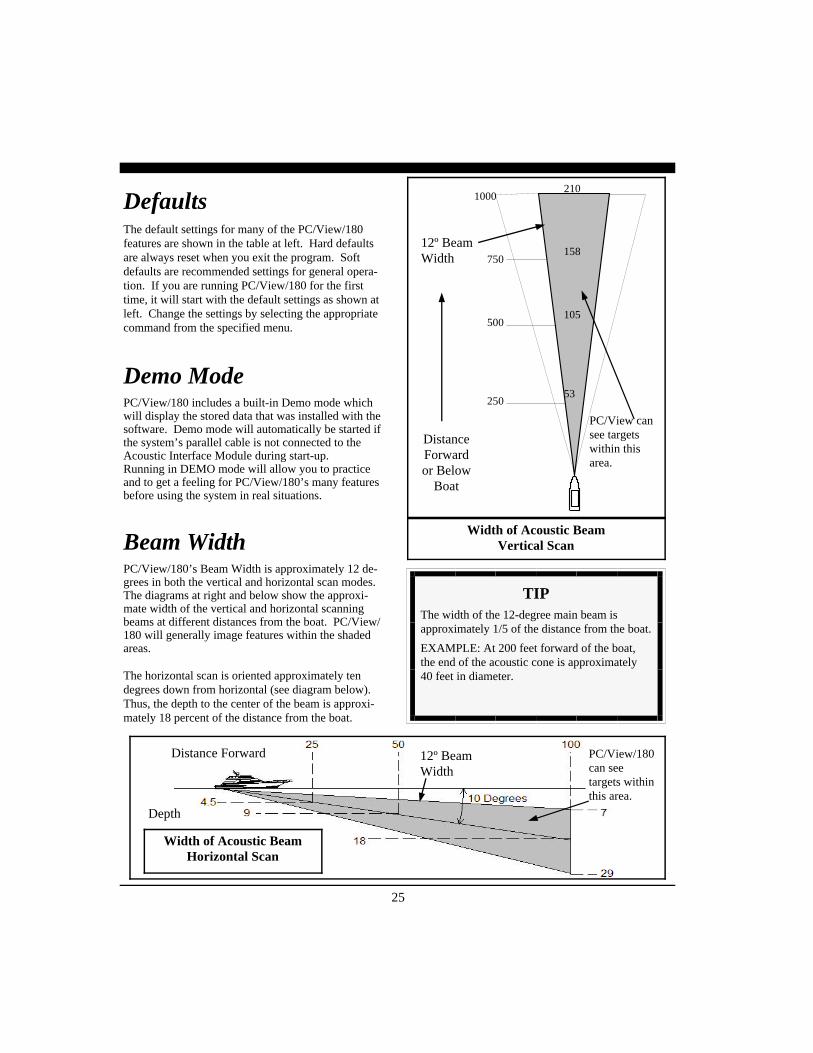
Beam WidthPC/View/180’s Beam Width is approximately 12 de-grees in both the vertical and horizontal scan modes.The diagrams at right and below show the approxi-mate width of the vertical and horizontal scanningbeams at different distances from the boat. PC/View/180 will generally image features within the shadedareas.
The horizontal scan is oriented approximately tendegrees down from horizontal (see diagram below).Thus, the depth to the center of the beam is approxi-mately 18 percent of the distance from the boat.
Width of Acoustic BeamVertical Scan
250
500
750
1000210
158
105
53
DistanceForwardor Below
Boat
PC/View cansee targetswithin thisarea.
12º BeamWidth
TIPThe width of the 12-degree main beam isapproximately 1/5 of the distance from the boat.
EXAMPLE: At 200 feet forward of the boat,the end of the acoustic cone is approximately40 feet in diameter.
Distance Forward 12º BeamWidth
Depth
Width of Acoustic BeamHorizontal Scan
PC/View/180can seetargets withinthis area.

26
6 Basic Operation
Screen Capture Alarm Reset
Toolbar
About PC/View
LongitudeLatitude
Water Depth
Units
Vessel Position
Getting StartedThis chapter will help you to learn the modes of oper-ation and the basic features of the PC/View/180 sys-tem. For more experienced users, this chapter can beused as a reference. Read Chapter 5 Quick Start tolearn how to start the PC//View180 software.
PC/View/180 is a Windows application with a stan-dard Windows menu structure. The PC/View/180screen includes a data display window as well as theToolbar and the Status Bar.
The Toolbar and Status Bar can be toggled on or offvia the View Menu.
The ToolbarThe Toolbar enables quick access to features whichare used often including:
• Screen Capture, which saves the current screento the hard disk (see p.43),
• About PC/View/180, which displays the softwareversion number, and
• Alarm Reset, which turns off the depth alarmafter it has been triggered (see p.38).
The Toolbar also includes two digital data displaysincluding:
• Depth beneath the transducer calculated by PC/View/180 with the current units, and
• Vessel Position information if it is available (e.g.38º 58.95N 121º 58.49W; refer to the discussionof NMEA navigation input in Chapter 7 Ad-vanced Operation).
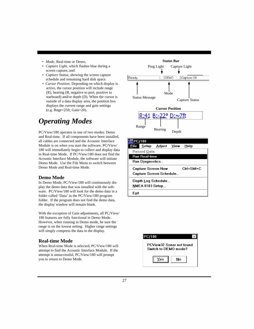
The Status BarThe Status Bar displays current information aboutPC/View/180 operation including:
• Status Message,• Ping Light, which alternates between red and
green on consecutive pings,
27
Status Bar
Status MessageMode
Capture Status
Ping Light Capture Light
RangeBearing
Depth
Cursor Position
• Mode, Real-time or Demo,• Capture Light, which flashes blue during a
screen capture, and• Capture Status, showing the screen capture
schedule and remaining hard disk space. • Cursor Position. Depending on which display is active, the cursor position will include range (R), bearing (B, negative to port, positive to starboard) and/or depth (D). When the cursor is outside of a data display area, the position box displays the current range and gain settings (e.g. Rnge=25ft; Gain=20).
Operating ModesPC/View/180 operates in one of two modes: Demoand Real-time. If all components have been installed,all cables are connected and the Acoustic InterfaceModule is on when you start the software, PC/View/180 will immediately begin to collect and display datain Real-time Mode. If PC/View/180 does not find theAcoustic Interface Module, the software will initiateDemo Mode. Use the File Menu to switch betweenDemo Mode and Real-time Mode.
Demo ModeIn Demo Mode, PC/View/180 will continuously dis-play the demo data that was installed with the soft-ware. PC/View/180 will look for the demo data in afolder called ‘Data’ in the PC/View/180 programfolder. If the program does not find the demo data,the display window will remain blank.
With the exception of Gain adjustments, all PC/View/180 features are fully functional in Demo Mode.However, when running in Demo mode, be sure therange is on the lowest setting. Higher range settingswill simply compress the data in the display.
Real-time ModeWhen Real-time Mode is selected, PC/View/180 willattempt to find the Acoustic Interface Module. If theattempt is unsuccessful, PC/View/180 will promptyou to return to Demo Mode.

28
Setting SystemParametersThere are several system parameters that you willusually need to set only once. Set these parametersusing the Parallel Port and Mount commands on theSetup menu.
Parallel Port AddressPC/View/180 must know the address of the parallelport on your computer to which you will connect theAcoustic Interface Module. The default parallel portaddress is 0x378. If you do not know what the paral-lel port address is, do not change it. Your parallelport address is most likely 0x378.
If you know that you are using a parallel port with anaddress other than 0x378, select Parallel Port... fromthe Setup menu and choose the correct address fromthe pull-down menu. The other two most commonparallel port addresses are 0x278 and 0x3BC.
Transducer Mount CorrectionsThe PC/View/180 software can compensate for minortransducer misalignments. These are important cor-rections, particularly if PC/View/180 is being used asa collision avoidance aid.
Level AdjustmentPC/View/180 can compensate for up to 14 degrees offore or aft tilt in the mounting of the vertical(starboard) scanning transducer.
To set the Transducer Level parameter, run PC/View/180 when the boat is over a known level bottom. Thevertical display should also appear level. If, however,the bottom is slanted upward (as shown in the“Before Level Adjust” picture at left), it means thatthe transducer was mounted with its nose pointingdown slightly. If the bottom slopes upwards by 10degrees, the Transducer Level correction should be 10degrees DOWN. If the bottom slopes downward,adjust the Transducer Level in the UP direction tocompensate.
Before Level Adjust
After Level Adjust

29
PC/180 Align AdjustmentPC/180 can compensate for up to 14 degrees ofmounting misalignment in either the port or starboarddirection for each of the two transducers. To set theTransducer Align corrections, point the boat directlytoward a known target (such as a piling) Dependingon the misalignment of the two transducers, you maysee two targets, the target may be off-center, or youmay not see the target at all.
To make the port-side alignment correction:1) Set sector width to 90 degrees and the sector steer
to 45 degrees. Refer to the diagram at right.2) Turn the port transducer knob in the port direction
until you see the whole target on the port-sidescan. (If the transducer is misaligned in the star-board direction, you may not need to turn theknob to see the whole target.)
3) Place the cursor at the center of the target and notethe bearing. Turn the port transducer knob thatnumber of degrees in the starboard direction.
To make the starboard-side align correction:1) Set sector width to 90 degrees and the sector steer
to 135 degrees.2) Turn the starboard transducer knob in the star-
board direction until you see the whole target onthe starboard-side scan.
3) Place the cursor at the center of the target and notethe bearing. Turn the starboard transducer knobthat number of degrees in the port direction.
When both corrections have been made, reset the sec-tor to the full 180 degrees. The entire target shouldbe visible and centered.
PC/180 Keel OffsetIf the transducers are mounted in positions above thedeepest point of your boat’s keel, PC/180 can auto-matically adjust the depth scale bars to compensatefor the offset. This will allow you to always workwith depths that are relative to the bottom of yourboat’s keel.
Move the slide bars to specify the depth of the keelbeneath each transducer.
A port-direction correction brings the
Bearing of the target center
Dial 13 degrees to starboardto center the target.

30
PC/View Align AdjustmentIn case the horizontal scanning transducer has beenmounted such that it points in a direction other thandead ahead, PC/View can compensate for up to 14degrees of misalignment either port or starboard.
To set the Transducer Align correction, point the boatdirectly toward a target (such as a piling, etc.) Thetarget should appear at the center of the horizontalscanning display. If, the target is off to the port(shown on the “Before Align Adjust” picture at left),it means that the transducer was mounted pointingslightly in the starboard direction. If the target is off-set to the port by 7 degrees, the Transducer Aligncorrection should be 7 degrees Stbd. If the targetappears off to the right (Stbd), adjust to the Port di-rection to bring the target back to the center position.
After setting the Transducer Align, view the HORZdisplay to verify the correction.
PC/View Keel OffsetIf the transducer(s) are mounted in a position abovethe deepest point of your boat’s keel, PC/View canautomatically adjust the depth scale bars to compen-sate for the offset. This will allow you to alwayswork with depths that are relative to the bottom ofyour boat’s keel.
Move the slide bar to specify the depth of the keelbeneath the transducer(s).
DisplaysPC/View/180 has five different scanning sonar dis-play windows. They are VERT, HORZ, DOWN,VSPLIT and HSPLIT, as shown at right. View a dis-play by clicking on its tab at the bottom of the win-dow.
For each of these displays, the transducer icon (shownat left) is displayed in its relative position with a yel-low line indicating the scan direction at each instant.Each display fills the current PC/View/180 window.Change the size and/or aspect ratio of the PC/View/180 window by dragging the sides or corners of thewindow.
After Align Adjust
Before Align Adjust
Transducer Icon

31
Vertical Display
PC/180 Horizontal Display
Downlooker Display
Vertical Split-Screen Display
PC/View Horizontal Split-Screen Display
32
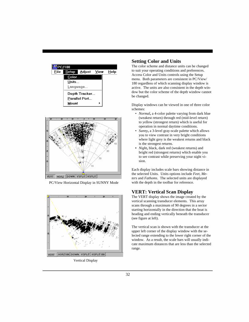
PC/View Horizontal Display in SUNNY Mode
Setting Color and UnitsThe color scheme and distance units can be changedto suit your operating conditions and preferences.Access Color and Units controls using the Setupmenu. Both parameters are consistent in PC/View/180 regardless of which scanning display window isactive. The units are also consistent in the depth win-dow but the color scheme of the depth window cannotbe changed.
Display windows can be viewed in one of three colorschemes:
• Normal, a 4-color palette varying from dark blue(weakest return) through red (mid-level return)to yellow (strongest return) which is useful foroperation in normal daytime conditions.
• Sunny, a 3-level gray-scale palette which allowsyou to view contrast in very bright conditionswhere light grey is the weakest returns and blackis the strongest returns.
• Night, black, dark red (weakest returns) andbright red (strongest returns) which enable youto see contrast while preserving your night vi-sion.
Each display includes scale bars showing distance inthe selected Units. Units options include Feet, Me-ters and Fathoms. The selected units are displayedwith the depth in the toolbar for reference.
VERT: Vertical Scan DisplayThe VERT display shows the image created by thevertical scanning transducer elements. This arrayscans through a maximum of 90 degrees in a sectorstarting horizontally in the direction that the boat isheading and ending vertically beneath the transducer(see figure at left).
The vertical scan is shown with the transducer at theupper left corner of the display window with the se-lected range extending to the lower right corner of thewindow. As a result, the scale bars will usually indi-cate maximum distances that are less than the selectedrange.
Vertical Display

33
HORZ180: Horizontal Scan DisplayThe HORZ180 display shows the image created bythe horizontal scanning transducer elements. Thisarray scans forward up to 180 degrees from port tostarboard in a sector that is tilted downward from hor-izontal by about 10 degrees (see figures at right).
The horizontal scan is shown with the transducer atthe bottom of the display window and the selectedrange extending to the top of the window, regardlessof the window’s width. Thus, data will be clipped onthe sides of a tall, narrow display (see figure below).
HORZ: Horizontal Scan DisplayThe PC/View HORZ display shows the image createdby the horizontal scanning transducer elements. Thisarray scans through a maximum of 90 degrees in asector centered about the boat’s heading and tilteddownward from horizontal by about 10 degrees (seefigure at lower right).
The horizontal scan is shown with the transducer atthe bottom of the display window and the selectedrange extending to the top of the window, regardlessof the window’s width. Thus, data will be clipped onthe sides of a tall, narrow display (see figure below).
PC/180 Horizontal Display
Scanning Directions.Vertical Scan modeshown above andHorizontal Scanmode below
34
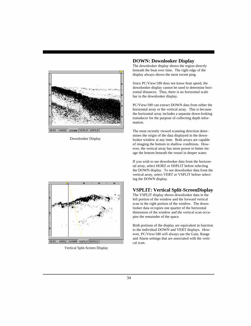
DOWN: Downlooker DisplayThe downlooker display shows the region directlybeneath the boat over time. The right edge of thedisplay always shows the most recent ping.
Since PC/View/180 does not know boat speed, thedownlooker display cannot be used to determine hori-zontal distances. Thus, there is no horizontal scalebar in the downlooker display.
PC/View/180 can extract DOWN data from either thehorizontal array or the vertical array. This is becausethe horizontal array includes a separate down-lookingtransducer for the purpose of collecting depth infor-mation.
The most recently viewed scanning direction deter-mines the origin of the data displayed in the down-looker window at any time. Both arrays are capableof imaging the bottom in shallow conditions. How-ever, the vertical array has more power to better im-age the bottom beneath the vessel in deeper water.
If you wish to see downlooker data from the horizon-tal array, select HORZ or HSPLIT before selectingthe DOWN display. To see downlooker data from thevertical array, select VERT or VSPLIT before select-ing the DOWN display.
VSPLIT: Vertical Split-ScreenDisplayThe VSPLIT display shows downlooker data in theleft portion of the window and the forward verticalscan in the right portion of the window. The down-looker data occupies one quarter of the horizontaldimension of the window and the vertical scan occu-pies the remainder of the space.
Both portions of the display are equivalent in functionto the individual DOWN and VERT displays. How-ever, PC/View/180 will always use the Gain, Rangeand Alarm settings that are associated with the verti-cal scan.
Downlooker Display
Vertical Split-Screen Display

35
HSPLIT180: Horizontal Split-ScreenDisplayThe HSPLIT180 display shows downlooker data inthe left portion of the window and the horizontal180-degree scan in the right portion of the window.The downlooker data occupies one quarter of thehorizontal dimension of the window and the hori-zontal scan occupies the remainder of the space.
The two portions of the display are equivalent infunction to the individual DOWN and HORZ180displays. However, PC/View/180 will always usethe Gain, Range and Alarm settings that are associ-ated with the horizontal scan.
HSPLIT: Horizontal Split-ScreenDisplayThe PC/View HSPLIT display shows downlookerdata in the left portion of the window and the for-ward horizontal scan in the right portion of the win-dow. The downlooker data occupies one quarter ofthe horizontal dimension of the window and the ver-tical scan occupies the remainder of the space.
Both portions of the display are equivalent in func-tion to the individual DOWN and HORZ displays.However, PC/View will always use the Gain, Rangeand Alarm settings that are associated with the hori-zontal scan.
Depth WindowIn addition to the five scanning sonar displays, PC/View/180 includes a separate depth window that canbe moved and resized to fill any portion of thescreen. Open the window by selecting Depth Dis-play from the View menu.
The depth window includes a large numerical dis-play as well as a graphical display of the depth overtime. The window stays open when the PC/View/180 application is minimized. Note that, if you useAlt-Tab to select PC/View/180 from several applica-tions running under Windows, an open depth displaywill remain in the background. Select Depth Displayfrom the View menu to bring the window to thefront.
Horizontal Split-Screen Display
Horizontal Split-Screen Display
36
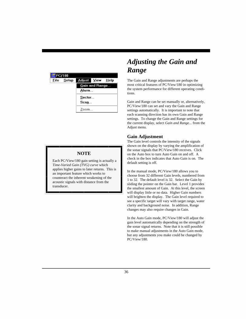
Adjusting the Gain andRangeThe Gain and Range adjustments are perhaps themost critical features of PC/View/180 in optimizingthe system performance for different operating condi-tions.
Gain and Range can be set manually or, alternatively,PC/View/180 can set and vary the Gain and Rangesettings automatically. It is important to note thateach scanning direction has its own Gain and Rangesettings. To change the Gain and Range settings forthe current display, select Gain and Range... from theAdjust menu.
Gain AdjustmentThe Gain level controls the intensity of the signalsshown on the display by varying the amplification ofthe sonar signals that PC/View/180 receives. Clickon the Auto box to turn Auto Gain on and off. Acheck in the box indicates that Auto Gain is on. Thedefault setting is off.
In the manual mode, PC/View/180 allows you tochoose from 32 different Gain levels, numbered from1 to 32. The default level is 32. Select the Gain bysliding the pointer on the Gain bar. Level 1 providesthe smallest amount of Gain. At this level, the screenwill display little or no data. Higher Gain numberswill brighten the display. The Gain level required tosee a specific target will vary with target range, waterclarity and background noise. In addition, Rangechanges may also require changes in Gain.
In the Auto Gain mode, PC/View/180 will adjust thegain level automatically depending on the strength ofthe sonar signal returns. Note that it is still possibleto make manual adjustments in the Auto Gain mode,but any adjustments you make could be changed byPC/View/180.
NOTEEach PC/View/180 gain setting is actually aTime-Varied Gain (TVG) curve whichapplies higher gains to later returns. This isan important feature which works tocounteract the inherent weakening of theacoustic signals with distance from thetransducer.
37
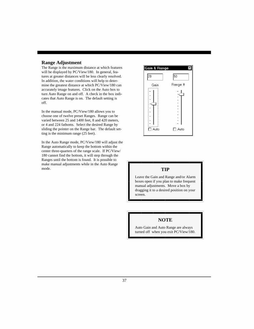
Range AdjustmentThe Range is the maximum distance at which featureswill be displayed by PC/View/180. In general, fea-tures at greater distances will be less clearly resolved.In addition, the water conditions will help to deter-mine the greatest distance at which PC/View/180 canaccurately image features. Click on the Auto box toturn Auto Range on and off. A check in the box indi-cates that Auto Range is on. The default setting isoff.
In the manual mode, PC/View/180 allows you tochoose one of twelve preset Ranges. Range can bevaried between 25 and 1400 feet, 8 and 420 meters,or 4 and 224 fathoms. Select the desired Range bysliding the pointer on the Range bar. The default set-ting is the minimum range (25 feet).
In the Auto Range mode, PC/View/180 will adjust theRange automatically to keep the bottom within thecenter three-quarters of the range scale. If PC/View/180 cannot find the bottom, it will step through theRanges until the bottom is found. It is possible tomake manual adjustments while in the Auto Rangemode. TIP
Leave the Gain and Range and/or Alarmboxes open if you plan to make frequentmanual adjustments. Move a box bydragging it to a desired position on yourscreen.
NOTEAuto Gain and Auto Range are alwaysturned off when you exit PC/View/180.

38
Using the AlarmPC/View/180 provides an audible alarm to alert youto nearby and shallow features. VERT, HORZ andDOWN displays use independent alarm settings. VS-PLIT and HSPLIT displays use the vertical and hori-zontal alarm settings, respectively.
Change the alarm settings by selecting Alarm fromthe Adjust menu. Turn the alarm on and off by click-ing on the Alarm On box. Select an alarm distance bymoving the slide bar.
The distance covered by the alarm will appear in thescale bar of the display as a solid magenta bar, and amagenta line or arc will cross the display at the speci-fied distance or depth. Vertical and downlookeralarms are triggered whenever a solidly displayedtarget appears shallower than the depth indicated bythe alarm bar. The horizontal alarm is triggeredwhenever a solidly displayed target appears closer tothe boat than the range indicated by the alarm arc.
Once the Alarm has been triggered, it will continuesounding until it has been reset. Reset the Alarm byclicking on the Clear Alarm button in the Alarm boxor by clicking on the yellow light bulb in the Toolbar.
Adjusting the ViewingAreaPC/View/180 provides several features which allowyou to modify the look of the display windows.These features can be accessed via the Adjust menu.Sector and Scan adjustments apply to the scanneddisplays, and each scan direction uses its own set-tings. In addition, a Zoom feature is available for theDOWN display.
NOTEAn alarm setting of zero is equivalent tohaving the alarm off.
39
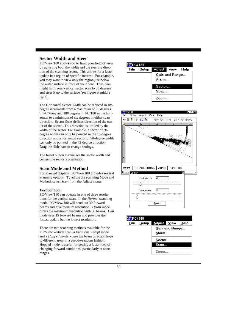
Sector Width and SteerPC/View/180 allows you to limit your field of viewby adjusting both the width and the steering direc-tion of the scanning sector. This allows for a fasterupdate in a region of specific interest. For example,you may want to view only the region just belowthe water surface in front of your boat. Thus, youmight limit your vertical sector scan to 30 degreesand steer it up to the surface (see figure at middleright).
The Horizontal Sector Width can be reduced in six-degree increments from a maximum of 90 degreesin PC/View and 180 degrees in PC/180 in the hori-zontal to a minimum of six degrees in either scandirection. Sector Steer defines direction of the cen-ter of the sector. This direction is limited by thewidth of the sector. For example, a sector of 30-degree width can only be pointed in the 15-degreedirection and a horizontal sector of 90-degree widthcan only be pointed in the 45-degree direction.Drag the slide bars to change settings.
The Reset button maximizes the sector width andcenters the sector’s orientation.
Scan Mode and MethodFor scanned displays, PC/View180 provides severalscanning options. To adjust the scanning Mode andMethod, select Scan from the Adjust menu.
Vertical ScanPC/View/180 can operate in one of three resolu-tions for the vertical scan. In the Normal scanningmode, PC/View/180 will send out 30 forwardbeams and give medium resolution. Detail modeoffers the maximum resolution with 90 beams. Fastmode uses 15 forward beams and provides thefastest update but the lowest resolution.
There are two scanning methods available for thePC/View vertical scan; a traditional Swept modeand a Hopped mode where the beam direction hopsto different areas in a pseudo-random fashion.Hopped mode is useful for getting a faster idea ofchanging forward conditions, particularly at shortranges.

40
Horizontal ScanPC/View can operate in one of three resolutions forthe vertical scan. In the Normal scanning mode, PC/View will send out 30 forward beams and givemedium resolution. Detail mode offers the maximumresolution with 90 beams. Fast mode uses 15 forwardbeams and provides the fastest update but the lowestresolution.
PC/180 operates in one of three resolutions for thehorizontal scan. In the Normal scanning mode, PC/180 will send out 60 forward beams and give mediumresolution. Detail mode offers the maximum resolu-tion with 180 beams. Fast mode uses 30 forwardbeams and provides the fastest update but the lowestresolution.
Four scanning methods are available for the PC/180horizontal scan. The Swept method scans from portto starboard over any sector width. The other threemethods are available only when the sector is set atthe full 180-degree width. All three of these methodsfill in beams in the port and starboard halves of thesector alternately. The Wiper method moves from leftto right through the two sector halves, beginning di-rectly to port and forward. The Converge methodbegins at the outer edges of the sector (directly portand starboard) and moves toward the center of thesector. The Diverge method begins at the center andmoves outward.
ZoomFor the DOWN display, PC/View/180 can show ahigh-resolution Zoom of one quarter of the depthrange. The high-resolution Zoom is useful if youwant to see extra detail on the bottom or in areasabove the bottom.
To activate the zoom, click in the Zoom On box. PC/View/180 will split the screen and begin to displayone of the seven available zoom sections in the lefthalf of the display. The standard display will con-tinue in the right half of the window with a high-lighted section in the scale bar to show the location ofthe zoomed section. Select a zoom section by movingthe slide bar up or down.

41
Adjusting the DepthTrackerWith every down-looking ping, the Depth Trackerattempts to find the bottom. The depth that is foundis displayed in the toolbar as well as the depth win-dow if it is open (see p.26 ). If the depth tracker can-not find the bottom, a question mark will be displayedin the toolbar. The tracked depth can be saved to afile and sent out over a serial port. Refer to Chapter 7for a discussion of this utility.
If Auto Range is on, PC/View/180 will use thetracked depth to adjust the range (see p.37 for a de-scription of Auto Range). If the depth tracker cannotfind the bottom, Auto Range will step through theavailable range scales until the bottom is found. Toadjust the parameters used by the depth tracker, selectDepth Tracker... from the Setup menu.
Surface MaskingThe Surface Masking feature allows you to specify arange near the water surface in which the depthtracker will ignore any incoming returns. The defaultSurface Masking is off.
Surface Masking is useful if there is a strong surfacereturn, abundant floating debris, bubbles under thehull or surface bait schools. With blanking off insuch situations, the depth tracker could mistake theseshallow returns for the bottom.
The maximum masking range is about 10 feet, 3 me-ters, or 1.6 fathoms. Use the slide bar to select themasking range. The selected masking range is shownin all display windows.
ThresholdTo avoid errant depth tracking on noise and sus-pended features, the depth tracker applies a Thresh-old. Normal is the default setting which should beused in most situations.

42
However, if the gain is set so that the screen is dark,revealing only obstacles and very bright mid-watertargets, the Low threshold setting may be required inorder to continue to track the depth.
Alternatively, if the gain is set high so that everythingis bright, the High threshold may be necessary toavoid tracking depth on bait balls and other strongmid-water returns.
NOTEDepth Tracker settings always return tothe defaults when you exit PC/View.

43
Saving Data with ScreenCaptureImages displayed in PC/View/180 can be saved usingthe Screen Capture feature. There are four ways tocapture an image:
1) Select Capture Screen Now from the File Menu.2) Use the keyboard shortcut Ctrl+Shft+C.3) Click on the Screen Capture button of the Tool-
bar.4) Use the Screen Capture Scheduler accessed from
the File Menu to automatically create periodicscreen captures.
PC/View180 will not carry out a requested or sched-uled screen capture if there is less than 20 MegaBytesof space remaining on your hard disk.
Whenever PC/View/180 does a screen capture, thescreen capture indicator (to the left of the screen cap-ture status box in the Status Bar) flashes blue. Eachscreen capture image is saved in the folder specifiedin the Screen Capture Scheduler.
The PC/View default folder is the Data folder in thePC/View program folder:
C:\Program Files\Interphase\PC/View\Data
The PC/180 default folder is the Data folder in thePC/180 program folder:
C:\Program Files\Interphase\PC180\Data
The Scheduler allows you to turn auto-saving on oroff (click on the box labeled Enable Screen Capture)and specify the frequency of auto-saving. You mayalso select a file format and change the destinationfolder. Both of the available file formats are bitmaps.The BMP format is more universal but the JPEG for-mat takes considerably less space.
19981118164240R0048G31.bmp
Year RangeMonth Gain
DayHour FormatMinute (bmp or jpg)
Second
Screen CaptureFile Name Format

44
This chapter describes several features of the PC/View/180 software which provide data handling andtroubleshooting for the more advanced operator.
Working with NMEANavigationPC/View/180 reads standard NMEA 0183 navigationstrings from a serial port, extracts the latitude andlongitude and displays this information in the toolbar.PC/View/180 accepts GGA, GLL, RMB and RMCstrings. To activate this feature, select NMEA 0183Setup… from the File menu, click in the check boxlabeled Enable NMEA 0183 Input and select the serialport to which navigation input is connected.
When NMEA 0183 input is enabled, PC/View/180will look for data coming from the serial port. If theNMEA strings are successfully parsed, PC/View/180will display the most recent latitude and longitude inthe navigation box on the toolbar. If PC/View/180does not find data or is unable to parse the data com-ing from the serial port, a series of dashes will be dis-played in the navigation box. A blank navigation boxindicates that NMEA 0183 input is disabled.
Use the following connections to your serial port. Ifyou have a 9-pin serial port:Pin# 2 = RX = OutPin# 3 = TX = InPin# 5 - Ground
If you have a 25-pin serial port:Pin# 2 = RX = OutPin# 3 = TX = InPin# 7 = Ground
7 Advanced Operation

45
Logging DepthPC/View/180 can log the tracked depth in a file andsend it out over a serial port. To activate this fea-ture, select Depth Log Schedule… from the Filemenu and click in the check box labeled EnableAutomatic Depth Log. Next, select a format for thelogged depth. Choose ASCII format or NMEA0183 sentence format. The ASCII format includesthe date, the time and the depth below the trans-ducer in the current Units.
For the NMEA 0183 format, any or all of four sen-tence types can be saved. NMEA 0183 format sen-tences begin with a dollar sign followed by the two-character talker identification followed by the three-character sentence type. The talker identification forPC/View/180 is SS, for scanning sonar. Data fieldsin the sentences are comma-delimited and the sen-tences end with a star followed by the checksum.PC/View/180 uses the following four sentencetypes:
DPT - Depth with Keel Offset. This sentence in-cludes the water depth, in meters, relative to thetransducer followed by the offset from the trans-ducer in meters.
DBT - Depth Below Transducer. This sentence in-cludes the water depth in feet; the water depth inmeters and the water depth in fathoms, all refer-enced to the transducer.
ZDA - Time and Date. This sentence includes, theUniversal Time Coordinated (UTC), the day, themonth, and the year, all in UTC, and the local zonehours and minutes (Atlantic Standard Time is localzone 05 hours, 00 minutes).
GLL - Geographic Position Lat/Lon. This sentenceincludes the latitude in degrees and decimal min-utes, north or south, the longitude in degrees anddecimal minutes, east or west, the UTC of the posi-tion and an indicator of the validity of the informa-tion. The talker identification for this string is thatof the navigation source rather than SS.
1999/03/31 16:43:29.01 12.2 ft.
YearMonth Depth
DayHour Units
MinuteSecond
ASCII Depth Format
46
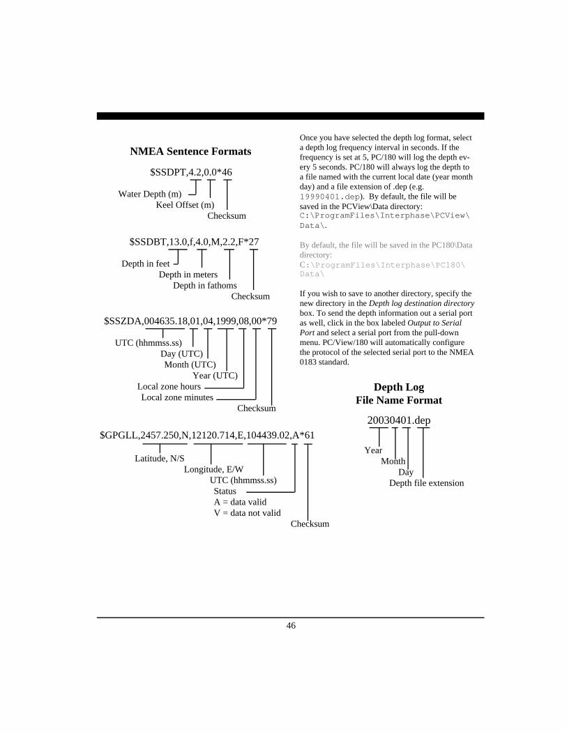
Once you have selected the depth log format, selecta depth log frequency interval in seconds. If thefrequency is set at 5, PC/180 will log the depth ev-ery 5 seconds. PC/180 will always log the depth toa file named with the current local date (year monthday) and a file extension of .dep (e.g.19990401.dep). By default, the file will besaved in the PCView\Data directory:C:\ProgramFiles\Interphase\PCView\Data\.
By default, the file will be saved in the PC180\Datadirectory:C:\ProgramFiles\Interphase\PC180\Data\
If you wish to save to another directory, specify thenew directory in the Depth log destination directorybox. To send the depth information out a serial portas well, click in the box labeled Output to SerialPort and select a serial port from the pull-downmenu. PC/View/180 will automatically configurethe protocol of the selected serial port to the NMEA0183 standard.
$SSDPT,4.2,0.0*46
Water Depth (m)Keel Offset (m)
Checksum
NMEA Sentence Formats
$SSDBT,13.0,f,4.0,M,2.2,F*27
Depth in feetDepth in meters
Depth in fathomsChecksum
$SSZDA,004635.18,01,04,1999,08,00*79
UTC (hhmmss.ss)Day (UTC)Month (UTC)
Year (UTC)Local zone hoursLocal zone minutes
Checksum
$GPGLL,2457.250,N,12120.714,E,104439.02,A*61
Latitude, N/SLongitude, E/W
UTC (hhmmss.ss)StatusA = data validV = data not valid
Checksum
20030401.dep
YearMonth
DayDepth file extension
Depth LogFile Name Format

47
Using the DiagnosticsThe PC/View/180 Diagnostics provide informationabout your computer system and the PC/View/180software. This tool enhances the ability of the Inter-phase Technical Support staff to troubleshoot anyproblem that you might have with your PC/View/180.
To gain the most information about your system, besure that the PC/View/180 hardware is connected toyour computer and turned on before selecting RunDiagnostics… from the File menu.
To save the results of the diagnostics, click on theCopy to Clipboard button and then paste into anyword processor, any email application or thenotepad. If you contact Interphase Technical Sup-port via fax (831-462-7444) phone (831-477-4944)or email ([email protected]), it willbe useful to include the diagnostics results in yourcorrespondence.

48
PrinciplesThe PC/View system provides a display of acousticechos from the underwater area beneath and ahead ofyour vessel. The Phased Array Transducer steers anacoustic beam over a sector which can be adjustedfrom 6 to 90 degrees width in the vertical orhorizontal direction.
The PC/180 system provides a display of acousticechos from the underwater area beneath and ahead ofyour vessel. The Phased Array Transducer steers anacoustic beam over a sector which can be adjustedfrom 6 to 90 degrees width in the vertical directionand from 6 to 180 degrees width in the horizontaldirection.
As the PC/View/180 steers the beam to differentpositions, it transmits a pulse of energy and then waitsa defined period of time (depending on the rangeselected) to receive returning echoes. As the energyfrom this acoustic beam strikes underwater objects orthe bottom, a portion of the energy is re-flected as anecho back to the transducer. When the echo isreceived at the transducer, it’s converted into a smallelectrical signal and processed for display.
Since PC/View/180 knows the direction in which itsent the transmit pulse and the time it took to receivethe return echo, it can determine the location of theobject or bottom that created the return echo. As thePC/View/180 sequentially steps through the scansector, the computer’s display shows a continuouslyupdated image of the returning echoes in theirapproximate positions relative to the vessel.
Interpreting the Vertical Display
In the vertical mode, PC/View/180 scans forwardfrom horizontal down to vertical beneath the vessel.Since the resulting display shows only the acousticechoes that are returned to the transducer, it cannotshow forward bottom conditions that are hidden from
8 Interpreting Displays
NOTEPoor water conditions such as surface chop,temperature inversion layers and muddy watermay degrade the PC/View’s performance

49
its field of view or are hidden due to obstructions inthe acoustic beam’s path through the water.
Forward Imaging CapabilitiesThe distance ahead of the vessel over which the PC/View/180 is capable of imaging features is depen-dent upon water depth, bottom structure and waterconditions. Under typical conditions, the PC/View/180 will show level or shallowing bottom contoursfor a distance forward of between 4-times and 6-times the water depth beneath the transducer. Ob-structions in the water may be seen at much greaterdistances (up to PC/View/180’s 1200-foot range).
Smooth bottom conditions far forward of the vesselare difficult to image as very little of the acousticenergy is reflected back as an echo (see the diagramat top left). Bottoms that are rough and rocky or aresloping upward will reflect more acoustic energyback to the transducer and will show strong far-forward returns (see diagram at middle right).
It is important to note that if the bottom is smoothand does not show up far-forward, acousticallyreflective obstructions in the same far-forward region(sea walls, large rocks, underwater shelves,submerged buoys, etc.) will typically send backstrong echoes (see diagram at bottom right).Regardless of the actual vertical dimension of suchfar-forward obstructions, they will often appear onthe PC/View/180 display as a vertical line or arc.
Transducer Sidelobe EffectThe PC/View/180’s transducer, like all transducers,does not form a perfect beam of acoustic energy.Some of the energy is contained in areas outside ofthe main beam called sidelobes (see diagram on nextpage). In some situations, sidelobes can lead toechoes that are not placed in the proper position onthe display.
As the PC/View/180 sends off its acoustic beam in aspecific direction, it assumes that any return echoesare within the main beam. However, if the sidelobeenergy strikes a reflective object, such as the bottom,creating a sufficiently strong echo, the PC/View/180will display the “false” return as if it were locatedwithin the main beam.
Strong Return from Wall Far-Forward
Weak Return From Far-Forward
Strong Return fromUp-sloping Bottom
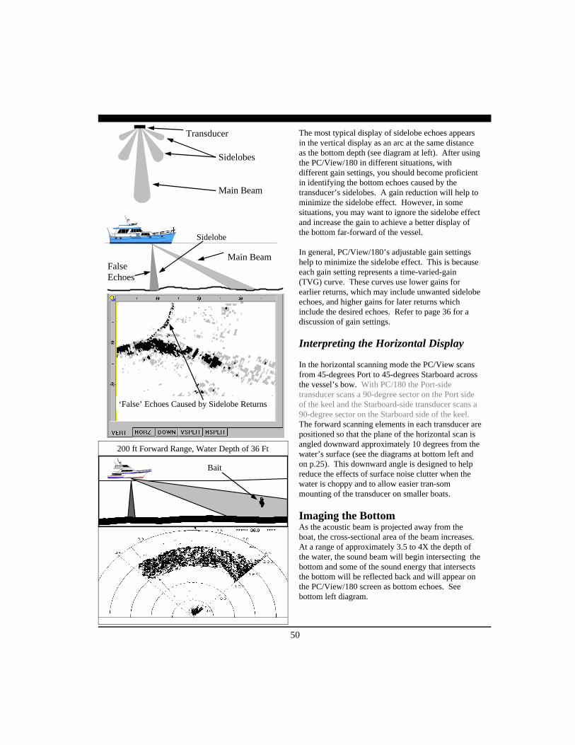
50
The most typical display of sidelobe echoes appearsin the vertical display as an arc at the same distanceas the bottom depth (see diagram at left). After usingthe PC/View/180 in different situations, withdifferent gain settings, you should become proficientin identifying the bottom echoes caused by thetransducer’s sidelobes. A gain reduction will help tominimize the sidelobe effect. However, in somesituations, you may want to ignore the sidelobe effectand increase the gain to achieve a better display ofthe bottom far-forward of the vessel.
In general, PC/View/180’s adjustable gain settingshelp to minimize the sidelobe effect. This is becauseeach gain setting represents a time-varied-gain(TVG) curve. These curves use lower gains forearlier returns, which may include unwanted sidelobeechoes, and higher gains for later returns whichinclude the desired echoes. Refer to page 36 for adiscussion of gain settings.
Interpreting the Horizontal Display
In the horizontal scanning mode the PC/View scansfrom 45-degrees Port to 45-degrees Starboard acrossthe vessel’s bow. With PC/180 the Port-sidetransducer scans a 90-degree sector on the Port sideof the keel and the Starboard-side transducer scans a90-degree sector on the Starboard side of the keel.The forward scanning elements in each transducer arepositioned so that the plane of the horizontal scan isangled downward approximately 10 degrees from thewater’s surface (see the diagrams at bottom left andon p.25). This downward angle is designed to helpreduce the effects of surface noise clutter when thewater is choppy and to allow easier tran-sommounting of the transducer on smaller boats.
Imaging the BottomAs the acoustic beam is projected away from theboat, the cross-sectional area of the beam increases.At a range of approximately 3.5 to 4X the depth ofthe water, the sound beam will begin intersecting thebottom and some of the sound energy that intersectsthe bottom will be reflected back and will appear onthe PC/View/180 screen as bottom echoes. Seebottom left diagram.
Bait
200 ft Forward Range, Water Depth of 36 Ft
‘False’ Echoes Caused by Sidelobe Returns
Sidelobes
Main Beam
FalseEchoes
Main Beam
Sidelobe
Transducer

51
It is important to understand that the PC/View/180will often see the bottom and will show it on theforward display. This display information can beused to help understand the structure of the bottomahead of the boat, but the bottom echoes can alsomask or be confused with other desired targets. Inthe diagram at bottom left, a bait ball or school offish is lost in the bottom echoes. However, as thevessel approaches the target, it will becomedistinct from the bottom echoes as it moves intothe nearer ranges.
Special SituationsWith experience you should be able to use the factthat the forward beam will show the bottom, toyour advantage. You will learn to recognizebottom structure such as varying water depthsacross the sector, drop-offs, ledges, and rockypatches on the bottom ahead. Two examples ofchanging bottom conditions are shown in thediagrams at right.
In the upper diagram, a shallow bottom in thestarboard direction is clearly imaged in thehorizontal scan. In the lower diagram, a channel isimaged. The deepest point of the channel ahead ofthe vessel is indicated by the gap in the bottomechoes.
Forward Imaging CapabilitiesIf the horizontal range setting is greater than theforward distance to the bottom, the PC/180 candetect targets at distances beyond where the beamhits the bottom. This is because the acoustic beamcan bounce off the bottom and keep going forwarduntil it strikes a solid object and then returns as anecho.
Even in shallow water it is possible to see severalhundred feet ahead by using this “bounce”technique. When looking far-forward in shallowsituations such as this, it is advisable to adjust thegain manually. Otherwise the Auto Gain featurewill reduce the gain because of the strong close-inbottom reflections. Refer to page 36 for adiscussion of gain settings.
Sides of Underwater Trench
Deeper water toport (left) of boat
Shallow rise on star-board (right) of boat
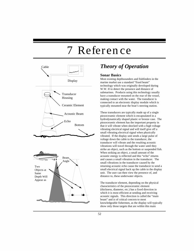
52
Theory of Operation
Sonar BasicsMost existing depthsounders and fishfinders in themarine market use a standard “fixed beam”technology which was originally developed duringW.W. II to detect the presence and distance ofsubmarines. Products using this technology usuallyhave a transducer mounted on the rear of the vessel,making contact with the water. The transducer isconnected to an electronic display module which istypically mounted near the boat’s steering station.
These transducers are typically made up of a singlepiezoceramic element which is encapsulated in ahydrodynamically shaped plastic or bronze case. Thepiezoceramic element has the important property inthat it will vibrate when shocked with a high voltagevibrating electrical signal and will itself give off asmall vibrating electrical signal when physicallyvibrated. If the display unit sends a large pulse ofvoltage down the cable to the transducer, thetransducer will vibrate and the resulting acousticvibrations will travel through the water until theystrike an object, such as the bottom or suspended fish.When striking an object, a small amount of theacoustic energy is reflected and this “echo” returnsand causes a small vibration in the transducer. Thesmall vibrations in the transducer caused by thereturning acoustic echo cause the transducer to send asmall electrical signal back up the cable to the displayunit. The user can then view the presence of, anddistance to, these underwater objects.
The transducer element, depending on the physicalcharacteristics of the piezoceramic element(thickness, diameter, etc.) has a fixed direction inwhich it is most efficient at sending and receivingacoustic signals. This direction is called the “mainbeam” and is of critical concern to mostknowledgeable fishermen, as the display will typicallyshow only those targets that are within this main
Cable
Acoustic Beam
Echo Bottom
Display
TransducerHousing
Ceramic Element
BeamAngle
TwoObjects atSameDepth WillAppear as
7 Reference
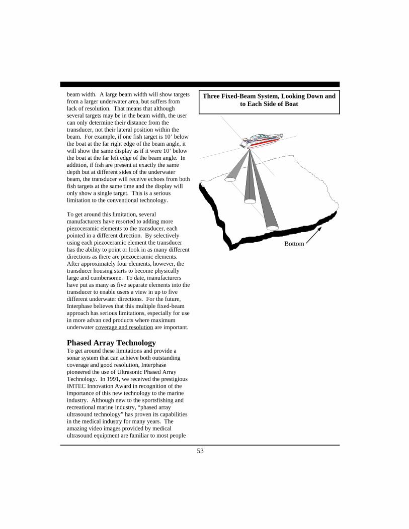
53
beam width. A large beam width will show targetsfrom a larger underwater area, but suffers fromlack of resolution. That means that althoughseveral targets may be in the beam width, the usercan only determine their distance from thetransducer, not their lateral position within thebeam. For example, if one fish target is 10’ belowthe boat at the far right edge of the beam angle, itwill show the same display as if it were 10’ belowthe boat at the far left edge of the beam angle. Inaddition, if fish are present at exactly the samedepth but at different sides of the underwaterbeam, the transducer will receive echoes from bothfish targets at the same time and the display willonly show a single target. This is a seriouslimitation to the conventional technology.
To get around this limitation, severalmanufacturers have resorted to adding morepiezoceramic elements to the transducer, eachpointed in a different direction. By selectivelyusing each piezoceramic element the transducerhas the ability to point or look in as many differentdirections as there are piezoceramic elements.After approximately four elements, however, thetransducer housing starts to become physicallylarge and cumbersome. To date, manufacturershave put as many as five separate elements into thetransducer to enable users a view in up to fivedifferent underwater directions. For the future,Interphase believes that this multiple fixed-beamapproach has serious limitations, especially for usein more advan ced products where maximumunderwater coverage and resolution are important.
Phased Array TechnologyTo get around these limitations and provide asonar system that can achieve both outstandingcoverage and good resolution, Interphasepioneered the use of Ultrasonic Phased ArrayTechnology. In 1991, we received the prestigiousIMTEC Innovation Award in recognition of theimportance of this new technology to the marineindustry. Although new to the sportsfishing andrecreational marine industry, “phased arrayultrasound technology” has proven its capabilitiesin the medical industry for many years. Theamazing video images provided by medicalultrasound equipment are familiar to most people
Bottom
Three Fixed-Beam System, Looking Down andto Each Side of Boat
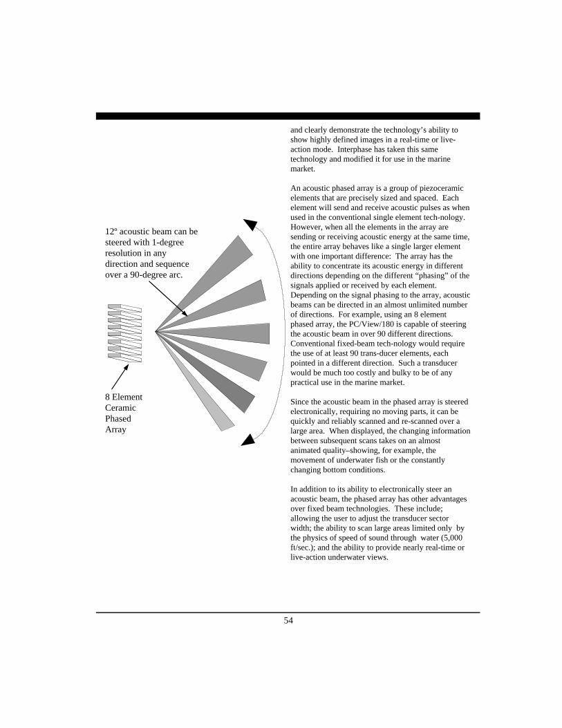
54
and clearly demonstrate the technology’s ability toshow highly defined images in a real-time or live-action mode. Interphase has taken this sametechnology and modified it for use in the marinemarket.
An acoustic phased array is a group of piezoceramicelements that are precisely sized and spaced. Eachelement will send and receive acoustic pulses as whenused in the conventional single element tech-nology.However, when all the elements in the array aresending or receiving acoustic energy at the same time,the entire array behaves like a single larger elementwith one important difference: The array has theability to concentrate its acoustic energy in differentdirections depending on the different “phasing” of thesignals applied or received by each element.Depending on the signal phasing to the array, acousticbeams can be directed in an almost unlimited numberof directions. For example, using an 8 elementphased array, the PC/View/180 is capable of steeringthe acoustic beam in over 90 different directions.Conventional fixed-beam tech-nology would requirethe use of at least 90 trans-ducer elements, eachpointed in a different direction. Such a transducerwould be much too costly and bulky to be of anypractical use in the marine market.
Since the acoustic beam in the phased array is steeredelectronically, requiring no moving parts, it can bequickly and reliably scanned and re-scanned over alarge area. When displayed, the changing informationbetween subsequent scans takes on an almostanimated quality–showing, for example, themovement of underwater fish or the constantlychanging bottom conditions.
In addition to its ability to electronically steer anacoustic beam, the phased array has other advantagesover fixed beam technologies. These include;allowing the user to adjust the transducer sectorwidth; the ability to scan large areas limited only bythe physics of speed of sound through water (5,000ft/sec.); and the ability to provide nearly real-time orlive-action underwater views.
8 ElementCeramicPhasedArray
12º acoustic beam can besteered with 1-degreeresolution in anydirection and sequenceover a 90-degree arc.

55
MaintenanceThe PC/View/180 Forward Scanning Sonar has been designed to provide reliable, trouble-free performancefor years. Follow the maintenance tips below to ensure that your PC/View/180 remains problem-free.
1) Keep your PC/View/180 Acoustic Interface Module clean and dry.
2) If the power cord in-line fuse is blown, replace it with a 2 amp fuse. NEVER REPLACE WITH AHIGHER AMP RATING ! If the fuse continues to blow, check the polarity of your 12 VDC powersource. If the polarity is correct, check with the Product Support Department at (831) 477-4944.
3) In order to protect your transducer from water damage, paint it with one of the following brands:Interlux-UltraCoat, Fiberglass Bottom Coat, Super Bottom Coat; Pettit-UniPoxy; Rule-Super KL, GlossDura Poxy. DO NOT use a solvent based paint. DO NOT allow any solvents, gasoline, acetone, etc.to come in contact with the transducer or head unit as these may dissolve the plastic materials.
Troubleshooting Guide If you are experiencing trouble with your PC/View/180, please refer to the following checklist:
PROBLEM SOLUTION
Acoustic Interface Module will not turnon.
Check power cord in-line fuse, battery voltage andpower connections. Also, check for continuitythrough the in-line fuse holder
Power cord in-line fuse blows repeatedly Wiring is reversed or there is excessive current fromthe battery. The red wire should be “+” (positive)and have continuity with pin #1 on the female sideof the power supply lead. Check the voltage to theAcoustic Interface Module. It should be less than16V and ideally 12-13V.
Screen remains blank in Demo Mode. PC/View/180 cannot find the demo data. Move thedata files (*.pcv) back into the Data folder in thePC/View or PC180 program folder.
Loses picture at speed. Adjust the transducer angle or placement. Makesure that the transducer is installed in the area whichhas the least amount of water turbulence.
Screen is full of noise, or has dots runningthrough it.
Reduce your gain setting and review the section oninterference.
Known flat bottom slopes up/down. Adjust the transducer angle or perform the level/align procedure to compensate for transducer mis-installation.
Digital water depth not working. Increase your gain, and check that you are in theproper depth range. Refer to the section on DepthTracker parameters.
56
Troubleshooting Guide, Continued
Below are outlined the 3 most common conflicts encountered using PC/View and PC/180. Please read theentire document before attempting any changes to the computer system or PC/View or PC/180 programs.Typically, these conflicts are noted by the message “PC32 Sonar Not Found. Switch To Demo Mode?”This indicates some conflict in the computer that prevents it from finding the equipment via the parallel port.Other messages may appear as noted below.
PC’s running Win2K and WinXP will always need setting changes to run the program, see pages 59-60.
Section 1 - Parallel Port Conflict:The PC/View and PC180 use interrupt IRQ 7 to communicate with the hardware via standard parallel port.Some computers may have another device installed that will also try to load on IRQ 7, creating a conflict.We will use Soundblaster as an example. When the driver is loading “aggressively” on IRQ 7 at boot time,the interrupt will be taken from the PC/View or PC180, and any other interrupt-driven application.
Note: many parallel port applications, such as printer drivers, are not interrupt-driven and therefore do notsuffer when this conflict exists.
There are two ways of addressing the conflict:1. Use the port before the Soundblaster can.2. Switch the Soundblaster to use another IRQ.
There are two ways to to resolve this conflict for Win95 and Win98. In order of preference they are:
A. Use the Device Manager to switch the Soundblaster’s interrupt. There are many ways to get to the DeviceManager. Perhaps the easiest to describe is through ‘My Computer’. Here’s the process for Windows 95/98:1. Right click on the ‘My Computer’ icon (usually upper left of desktop).2. Select the ‘Properties’ option.3. Select the ‘Device Manager’ tab.4. Right click on the ‘Computer’ icon at the top of the Device Manager box.5. Select the ‘Properties’ option.6. Select the ‘Reserve Resources’ tab.7. Click on the ‘Add’ button.8. Type “07” in the edit box.9. You will now see a little “07” in the Reserved Resources box.10. Reboot.11. If you watch the boot cycle carefully, you should see the Soundblaster load on IRQ 5.12 If your system acts funny or gives you new LPT messages/warnings, just revert to the unreserved
IRQ and try our DriverLoadMethod.exe.Computers running Win2K or WinXP use a different method to access and alter the Port Settings. Please seethe note at the end of section 2, LPT Port Address.
PROBLEM SOLUTION
Will not run in Real-Time Mode.Note: Computer conflicts are a com-mon source of Real-Time interruption.The most common conflicts and solu-tions are listed below.
Verify that the parallel data cable is connected to theAcoustic Interface Module and your computer, andthat the Acoustic Interface Module is on. Check tosee that the proper parallel port address is selected.Select Run Real-time from the File menu.
57
B. Use our “patch” program called ‘DriverLoadMethod.exe’ which ships and installs with all Windowsversions of PC/View & PC/180 X.2 and beyond. Within D.L.M., the PC/View parallel port driver can beconfigured for boot time load instead of the default runtime load. This is a relatively aggressive approach andshould be avoided if possible.
Here’s the process for Windows 95/98:
1. Double click : My Computer: (C:) Drive: Programs File: Interphase File: PC/View or PC/1802. Open DriverLoadMethod.exe3. Uncheck box marked Load Driver at Runtime.4. Reboot.
Section 2 - LPT Port Adress:There are 3 to select from in the Setup menu under Parallel Port, 0X378, 0X3BC and 0X278. The default is0X378. Check to be certain that the PC/View or PC/180 program is using the same address as the PC’sparallel port. The preffered setting is 0X378 (sometimes written as 0378).
The parallel port resources can be located as follows:1. Right click on the ‘My Computer’ icon.2. Click on the ‘Device Manager’ tab.3. Double click on ‘Port (COM &LPT)’.4. Double click on ‘Printer Port’.5. Click on ‘Resources Tab’.6. Select ‘Resource Type’ (typically 0378-037F).7. Make changes as needed.8. Reboot.
Computers using Win2K and WinXP Access both of the features in the following manner:1. Got to ‘My Computer’ either via the desktop icon or Start menu.2. Under the ‘System Tasks’ heading, click on ‘View System Information’.3. Click on the ‘Hardware’ tab.4. Click on ‘Device Manager’.5. Scroll down to ‘Ports’ and open by clicking on the ‘+’.6. Double click on ‘Printer Port’.7. Click on the ‘Resources’ tab. The default settings should be “I/O Range 0378 – 037F” and “IRQ 07”.
These are the proper and preferred settings for PC/View and PC/180. If they are not set up this waythen the I/O range can be changed here. It is possible to change the LPT Port Address within the PC/View and PC/180 to match other I/O settings on the PC. This is not preferred, but can be attempted ifthe preferred settings are not operating.
LPT Port Settings in WinXP can also be viewed and changed by the following method:1. Go to ‘My Computer’ either via the desktop icon or Start menu.2. Under the ‘System Tasks’ heading, click on ‘Change a Setting’.3. Double Click on ‘System’.4. Click on the ‘Hardware’ tab.5. Click on ‘Device Manager’.6. Scroll down to ‘Ports’ and open by clicking on the ‘+’.7. Double click on ‘Printer Port (LPT1)’.

58
8. Click on the ‘Resources’ tab. The default settings should be “I/O Range 0378 – 037F” and “IRQ 07”.9. Highlight ‘I/O Range’.10. Next to the text “Headings Based on…” scroll down to desired configuration.11. Once the desired configuration appears after ‘I/O Range’ Click ‘OK’.12. The message “ You adjusted one or more settings manuall. If you continue, these settings will be
assigned to the device. Do you want to continue?” will appear. Click on ‘Yes’.
In addition, it is ESSENTIAL that the Port Settings allow PC/View or PC/180 to to use the port.1. Follow steps 1-6 above.2. Click on the ‘Port Settings’ tab.Select “Use Any Interrupt Assigned”. The default is “Never Use An Interrupt”. PC/View and PC/180cannot operate if this default setting is selected.
Section 3 - The Parallel Port Protocol or BIOS Mode:This setting is typically made from the BIOS configuration that is accessible during the boot cycle. Duringthe boot sequence, you can access a utility called SETUP by pressing either “Del” “Esc” “Ctrl-Esc” or “F2”.This varies from system to system. Dell computers running both Win2K and WinXP access by pressing F2.
The three major BIOS manufactureres (AMI, Award, Phoenix) each provide a different Setup utility, thoughthey are similar in function. Select the option that indicates “Ports” or “Integrated Peripherals” or PeripheralSetup” or simply “Advanced”.
Scroll down to the Parallel Port Mode setting and select it.
Us the arrow keys (or PgUp/PgDn depending on brand) to set the mode to one of the following: Bi-Directional, Standard or SPP. These are the most often used modes that work with the program.
Other settings might include but are not limited to: Output Only, EPP or ECP. If you find that one settingdoes not work, try another.
Note: There are some exceptions, most noteably Sony Vio, Gateway and Panasonic laptops which operateusing the ECP mode.
Save and exit using the key sequence indicated at the bottom of the screen, usually “ESC” or “F10” orboth.You may need to escape back to the main setup screen before you can save and exit.
Once out of the Setup utility, the boot sequence will continue.
- The IBM Thinkpad also uses the ECP mode. However, it is accessed differently than other brands asfollows: Control Panel: Thinkpad Config: Device Config: Parallel Port: Operating Mode: Select ECP.
- Dell computers running Win2K offer a setting under parellel port settings called “AT”. Access the settingunder ‘Integrated Devices’. The “AT” setting should be selected over “ECP or “EPP”. Further, there is aneed to alter the port’s interrupt settings in the Device Manager. A button called “Never use an Interrupt” isnormally checked. This box must be unchecked and the “Use any Interrupt Assigned” button should bechecked. One way to access the Device manager is as follows:
59
1. Right click on ‘My Computer’.2. Select ‘Properties’.3. Choose the ‘Hardware’ tab.4. Click on the ‘Device Manager’ button in the Device Manager box.5. Scroll down to ‘Ports’ and open by clicking on the ‘+’.6. Double click on ‘LPT1’ or “ECP Parallel Port’.7. Choose the ‘Port Settings’ tab.8. Select radio option 3 ‘Use any Interrupt assigned to the Port’.9. Click Ok.10. Close the Device Manager window using the ‘X’ button in the upper right.11. Close the Properties window with the OK button.
Dell computers running WinXP should use the default setting of ‘Bi-Directional’. To access the bios:
1. Press F2 during the boot sequence.2. Toggle to ‘Advanced’.3. Under ‘Peripheral Configuration’ go to ‘Mode’.4. Select ‘Bi-Directional’. Note: Output Only, ECP and EPP are also available. In our tests using a
Dell Dimension 4400 running WinXP(HE) the ‘Bi-Directional‘ setting allowed PC/View and PC/180 to run. No other bios setting worked. This has also been confirmed to work on XP Pro.
For WinXP the critical settings are:1. ‘Use Any Interrupt Assigned’ described at the end of section.2. Disable the ‘Compatability’ option. This option allows WinXP to operate as if it us using an older
version of Windows (95, 98, 2000). Our program will not operate if any of these options isselected. The message “WinVUDLL Can’t Create ISR Event” will appear if this option is activeand the program will not run. The method for doing this is outlined below:
From the PC/View or PC/180 ICON on the desktop:1. Right Click on the icon.2. Scroll down to and click on ‘Properties’.3. Click on the ‘Compatability’ tab.4. Unselect “Run this program in compatability mode for”.5. Also under this selection there are the following options: “Run in 256 Colors”, “Run in 640x480
screen resolution”, “Disable Visual Themes”. ALL of the options should be unselected for bestvisual performance of PC/View and PC/180.

60
Interference ProblemsInterference can come from several sources. Themost common of these are:
1) Other nearby depth sounders operating at thesame frequency.
2) Radiated interference from the boat’s electricalsystem (alternator, distributor and spark plugs)or from nearby equipment that radiates electri-cal noise.
3) Conducted interference usually occurs whenthe PC/View/180 shares a 12VDC power leadwith other noisy equipment (i.e.; bilge pumps,motors, refrigeration systems, autopilots, etc.)
Interference caused by nearby depth sounders oper-ating on or near the same frequency as the PC/View/180 will typically appear as “rabbit tracks”that march up and down the screen. Reducing thegain will help minimize this problem.
Radiated interference caused by the boat’s enginecan usually be identified by observing the PC/View/180 with both the engine running and turned off. Ifthe interference disappears when the engine isturned off, it is safe to assume that the engine is thesource of the interference.
This type of interference can usually be eliminatedby using the same techniques used in the automo-tive industry to eliminate interference to car radios,CB’s, etc. The following actions may be required:
1) Reduce the Gain setting to minimize interfer-ence.
2) Make sure your boat uses resistor type sparkplugs and plug wiring.
3) Install a suppressor on the center lead of thedistributor.
4) Install an alternator filter to smooth the alterna-tor’s output signal.
Interference may also be caused by radiation fromother nearby equipment and can be detected byturning off all other equipment and observing thePC/View/180 display as each suspected source isturned back on. This type of interference can usu-
ally be eliminated by moving the PC/View/180Acoustic Interface Module away from the sourceand checking to ensure that the interfering source isproperly grounded.
Interference causing the display to be unstable, topulsate or periodically change size is usually causedwhen another piece of equipment shares the same12 VDC power leads from the battery. This prob-lem is especially severe when equipment requiringlarge current surges (i.e.; autopilots, refrigerators,or bilge pumps) share the same power leads. Mini-mize this type of interference by running the PC/View/180’s 12VDC power leads, or those of theinterfering equipment, directly to the battery.
Alternatively, you may find it helpful to install aseparate dedicated power supply battery that is usedonly to run your electronic gear (e.g.; fishfinders,VHF radios, radar units, etc.). If your unit shuts offduring low voltage situations, such as when crank-ing your engine starter, you may want to install anisolator switch with an “A/B” type of battery sys-tem. An “A/B” system allows you to run your elec-tronic gear on one battery, while the starter and al-ternator are hooked up to the other battery.
Your authorized marine electronics dealer is famil-iar with the methods of reducing electrical interfer-ence and is qualified to assist you should a problempersist.
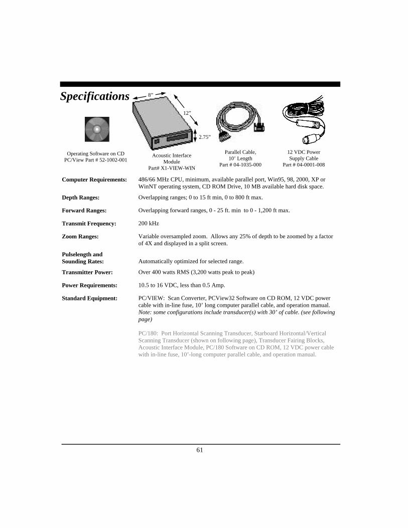
61
Specifications
12 VDC PowerSupply Cable
Part # 04-0001-008
Operating Software on CDPC/View Part # 52-1002-001
Acoustic InterfaceModule
Part# X1-VIEW-WIN
Parallel Cable,10’ Length
Part # 04-1035-000
Computer Requirements: 486/66 MHz CPU, minimum, available parallel port, Win95, 98, 2000, XP orWinNT operating system, CD ROM Drive, 10 MB available hard disk space.
Depth Ranges: Overlapping ranges; 0 to 15 ft min, 0 to 800 ft max.
Forward Ranges: Overlapping forward ranges, 0 - 25 ft. min to 0 - 1,200 ft max.
Transmit Frequency: 200 kHz
Zoom Ranges: Variable oversampled zoom. Allows any 25% of depth to be zoomed by a factorof 4X and displayed in a split screen.
Pulselength andSounding Rates: Automatically optimized for selected range.
Transmitter Power: Over 400 watts RMS (3,200 watts peak to peak)
Power Requirements: 10.5 to 16 VDC, less than 0.5 Amp.
Standard Equipment: PC/VIEW: Scan Converter, PCView32 Software on CD ROM, 12 VDC powercable with in-line fuse, 10’ long computer parallel cable, and operation manual.Note: some configurations include transducer(s) with 30’ of cable. (see followingpage)
PC/180: Port Horizontal Scanning Transducer, Starboard Horizontal/VerticalScanning Transducer (shown on following page), Transducer Fairing Blocks,Acoustic Interface Module, PC/180 Software on CD ROM, 12 VDC power cablewith in-line fuse, 10’-long computer parallel cable, and operation manual.
8”
12”
2.75”

62
Transducer specifications subject to change without notice.
STARBOARD Vertical Scanning andHorizontal Starboard Scanning Transducer
Part # T1-0200-036
PORT HorizontalPort Scanning Transducer
Part# T1-0200-35
PC/180 Transducer Configuration
Transducer Fairing Blocks included with PC/180.
Transducer specifications subject to change without notice.
SingleThru-Hull Transducer
Part # T1-I200-032
Two Transom TransducersPart # T1-0200-025
& T1-0200-028
Two Thru-Hull TransducersPart # T1-I200-026
& T1-I200-029
PC/View Transducer Options
Fairing blocks for PC/View thru-hull transducers:For T1-I200-032 - Part# 42-2005-000For T1-I200-026 and T1-I200-029 - Part# 42-2004-000

63
How to Obtain ServiceIf you feel your set is not operating properly, first refer to the sections of this manual on Troubleshooting andInterference Problems. This information solves the most common problems. If problems persist, please callInterphase Technical Service at (831) 477-4944 or send your unit in with the information below filled out.
If you do need to return your set, send it to the following address:
Service DepartmentInterphase Technologies, Inc.2880 Research Park Drive, Suite 140Soquel, CA 95073
In addition, to speed your repair please fill out the following, tear this page out of the manual (or photocopyit), and tape it to your unit for our technicians to review. For fastest warranty service, include a copy of yourpurchase receipt to verify the purchase date.
RETURN TO: (Your Name)
(Street Address - No P.O. Boxes Please)
(City) (State) (Zip)
Daytime Telephone: ( ) Evening Telephone: ( )
Model: PC/180 Serial #:
Purchase Date / /
Type of transducer: Transom mount Thru-Hull Other
Please describe the problems you are having with the unit in as much detail as possible in the space below.Please use another sheet of paper if necessary.

64
AAbout PC/View/180 26Acoustic Interface Module 7, 60, 61
PC/180 Installation 8PC/View Installation 14maintenance 55
Advanced Operation 44-47Alarm
reset 26, 38setting parameters 38
Auto Gain 36-37Auto Range 37, 41
BBasic Operation 26-43Beam Width 25Bottom Imaging 50
CCables 7, 12-16, 20-21, 60Color 32Computer Requirements 22, 61Cursor Position 27
DDefaults 25Demo Mode 25, 27Depth
Logging 45-46Display 35
Depth Tracker 26, 41-42Surface Masking 41Threshold 41-42
Depth Window 35Diagnostics 47Displays 30-35
DOWN: Downlooker 34HORZ: Horizontal Scan 33HSPLIT: Horizontal Split-Screen 35
IndexVERT: Vertical Scan 48-51VSPLIT: Vertical Split-Screen 32Interpreting 48-51
FFairing Blocks 11, 19, 61-62Forward Imaging Capabilities 25, 49, 51
GGain
Adjustment 36Automatic 36-37In Demo Mode 27Time-Varied 36, 50
HHorizontal Scan 6, 19, 15, 25, 30-35, 50-51HORZ: Horizontal Scan Displays 33HSPLIT: Horizontal Split-Screen Displays 35
IInstallation 8-23
PC/180 Acoustic Interface Module 13PC/View Acoustic Interface Module 21PC/180 Transducers 8-13PC/View Transducers 14-21
Interference Problems 13, 60
MMaintenance 55Microsoft Windows 22, 61Modes of Operation 25, 27
N

65
Navigation Warning 6, 24NMEA Navigation 44
P
Parallel PortAddress 28, 57-58Cable 7-8, 14, 61
Phased Array Technology 53-54Position
Cursor 27Vessel 44
Power Cable 7, 60
QQuick Start 24-25
RRange
Adjustment ` 37Automatic 37In Demo Mode 27
Real-Time Mode 27
SScale Bars 32Scan Mode and Method 39-40Screen Capture 27, 43Screen Capture Scheduler 43Sector Width and Steer 39Service 7, 63Setup.exe 22Sidelobe Effects 49-50Software
CD, Installation 7, 22Starting 24
Sonar Basics 52Specifications 61Split-Screen Displays 31, 34-35Status Bar 26Surface Masking 41System Parameters 28-30
T
Theory of Operation 52-54Threshold 41-42Time-Varied Gain 36, 50Toolbar 26Tools Required for Transducer Installation
PC/180 12PC/View 16
TransducerAlign Adjustment 29, 30Cable 7, 12-16, 20-21, 60Icon 30PC/180 Installation 9-13PC/View Installation 14-21Keel Offset 29, 30Level Adjustment 28PC/180 Mounting Location 6, 10PC/View Moutning Location 16-19Mounting Corrections 28-30Options 7, 62Orientation 9-10, 15-18, 20
Troubleshooting 47, 55-59
U
Units 26, 32Unpacking and Inspection 7
V
VERT: Vertical Scan Display 32Vertical Scan 25, 31-32, 34, 48-50Vessel Position 26, 44VSPLIT: Vertical Split-Screen Display 34
WWarranty 6-7, 67
ZZoom 40

66
NOTES:

67
Interphase Technologies, Inc.Limited Warranty
This product is covered by a 5 year limited warranty.
Any unit that fails during the first year of the warranty period will, at Interphase’soption, be repaired or replaced at no charge to the customer provided it is returnedto Interphase, freight prepaid with proof of date of purchase and a description ofthe malfunction. Repair or replacement during the warranty period will not extendthe basic warranty period.
Units that fail during the second to fifth year of the warranty period will be repairdor replaced at a flat rate charge which is revised each year. The defective unitmust be returned to Interphase, freight pepaid with proof of date of purchase and adescription of the malfunction.
This warranty does not apply to an Interphase product that has failed due toimproper installation, misuse, or accident, nor does it apply to products whichhave been repaired or altered outside the Interphase factory.
Any costs incurred with transducer replacement are specifically excluded from thiswarranty other than the cost of the transducer itself.
This warranty does not include incidental or consequential damages andInterphase disclaims any liability for any such damages. All implied warranties,if any, are limited in duration to the above stated one year warranty period. Somestates and provinces do not allow the exclusion or limitation of incidental orconsequential damages, therefore, the above limitations may not apply to you.
The completion and return of the enclosed Warranty Registration Card is acondition precedent to the warranty coverage.
This warranty gives you specific legal rights which may vary from state to stateand province to province. This warranty is limited only to the original purchaserof the unit.

68