Internetworking With TCP/IP - iut.ac.irit.iut.ac.ir/sites/fsites/it/files/u4/uploads/Addressing in...
47
Internetworking With TCP/IP IPv4 Addressing in Ethernet, IEEE 802.3, Token Ring, X.25, SNA, FDDI, …. TCP UDP Telnet Gopher NFS FTP X Win TFTP SMTP SNMP REXEC DNS RPC Application Layer Transport Layer Network Layer Link Interface ICMP IGMP IP RARP ARP Parviz Kermani
Transcript of Internetworking With TCP/IP - iut.ac.irit.iut.ac.ir/sites/fsites/it/files/u4/uploads/Addressing in...

Internetworking With TCP/IP
IPv4 Addressing in
Ethernet, IEEE 802.3, Token Ring, X.25, SNA, FDDI, ….
TCP UDP
Telnet Gopher NFS
FTP X Win TFTP
SMTP SNMP
REXEC DNS RPC
Application Layer
Transport Layer
Network Layer
Link Interface
ICMP IGMPIP RARPARP
Parviz Kermani
Legends
Back to previous foil
Page contains animation
End of animation
2IP Addressing
Acknowledgement
Part of the following pages were taken from materials provided by other authors and companies
CiscoLecture slides of “Computer Networking: A Top Down Approach” by Jim Kurose and Keith Ross“CCENT/CCNA ICND1 & 2- Official Exam Certification Guide”, Wendell Odom, Cisco Press
3IP Addressing

Internet in a Nutshell
Ethernet, IEEE 802.3, Token Ring, X.25, SNA, FDDI, ….
TCP UDP
Telnet Gopher NFS
FTP X Win TFTP
SMTP SNMP
REXEC DNS RPC
Application Layer
Transport Layer
Network Layer
Link Interface
ICMP IGMPIP RARPARP
4IP Addressing

Addresses & Names
Hardware (Layer 2)Lowest levelEthernet (MAC), Serial point-to-point, ..
Network (Layer 3)IPIPX, SNA, others
Application (layer 5?)Names (URL), alias, ..
All are important and neededUltimately, all deliveries move over the physical layerNote: Port address not under discussion (Transport)
5IP Addressing

Layer 2 Addressing
Uses MAC address Assigned to end devices
6IP Addressing

Layer 3 Addressing
Each Network Architecture has its own Layer 3 address format. OSI uses NSAP. TCP/IP uses IP
7IP Addressing
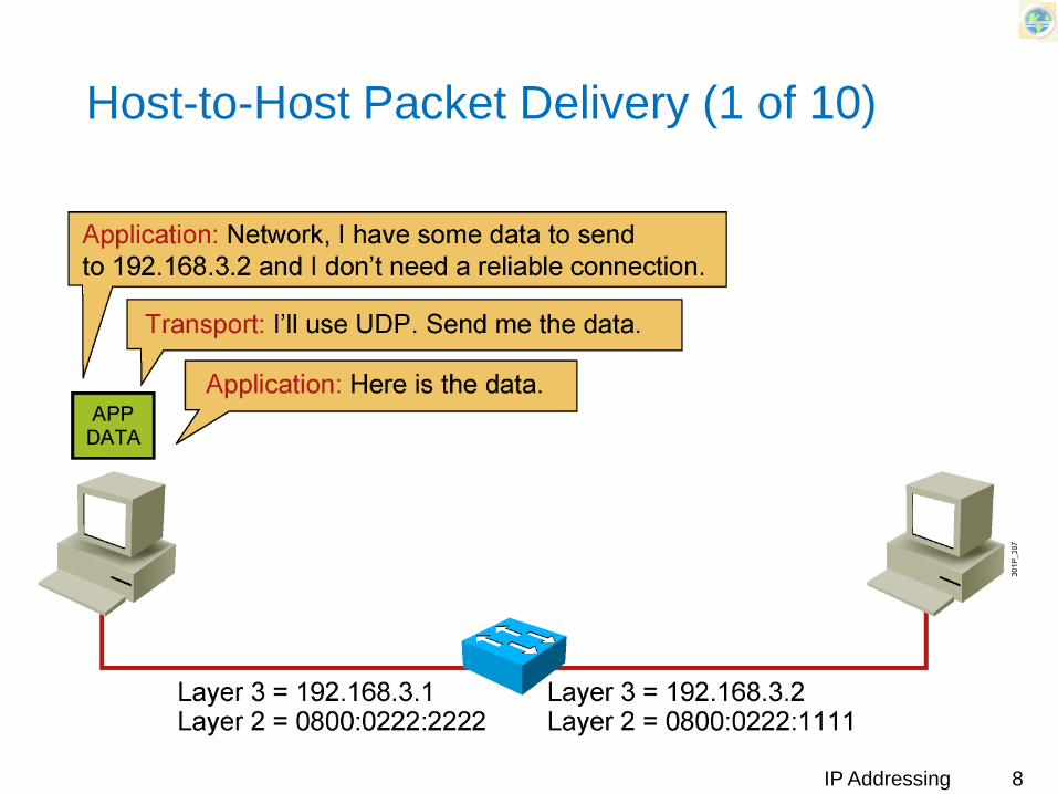
Host-to-Host Packet Delivery (1 of 10)
8IP Addressing
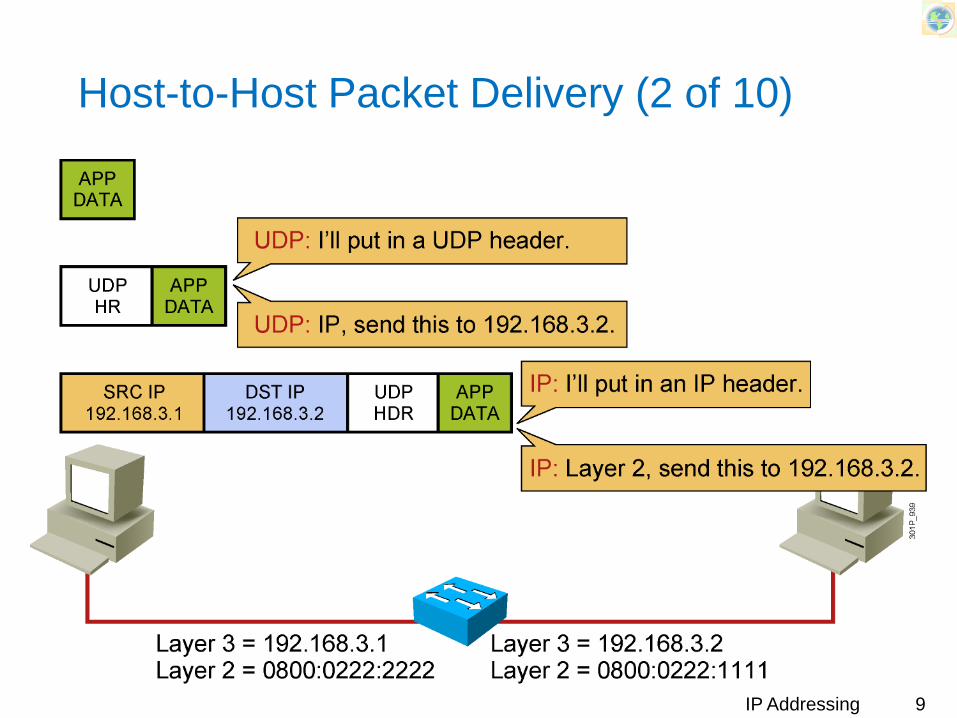
Host-to-Host Packet Delivery (2 of 10)
9IP Addressing
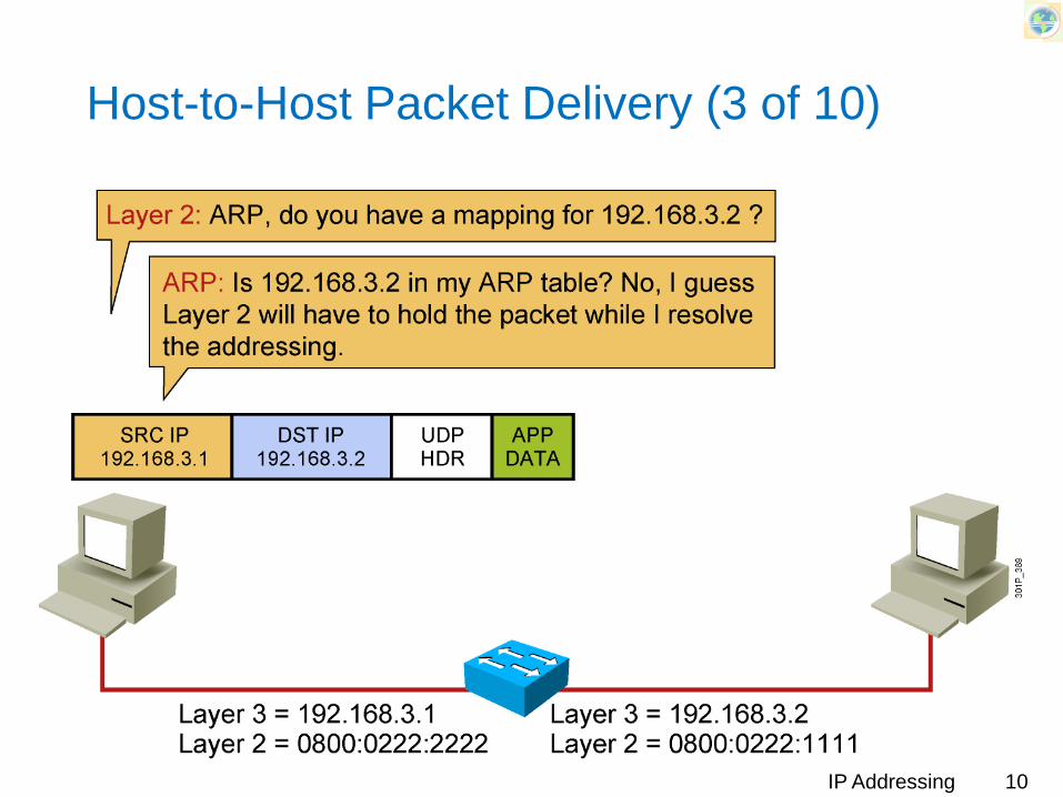
Host-to-Host Packet Delivery (3 of 10)
10IP Addressing
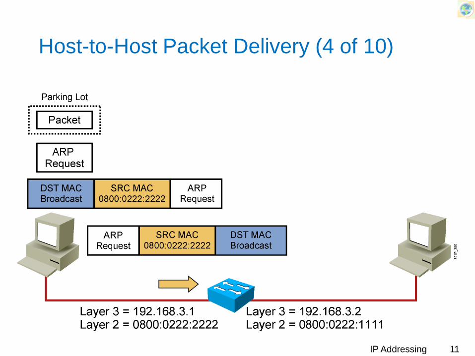
Host-to-Host Packet Delivery (4 of 10)
11IP Addressing

Host-to-Host Packet Delivery (5 of 10)
12IP Addressing
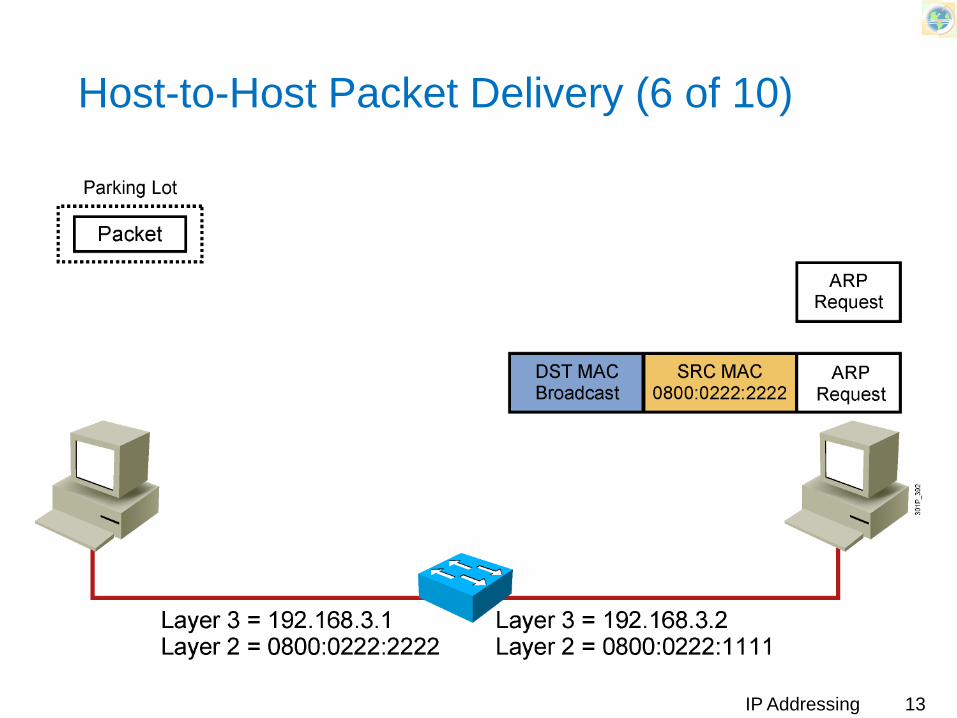
Host-to-Host Packet Delivery (6 of 10)
13IP Addressing

Host-to-Host Packet Delivery (7 of 10)
14IP Addressing

Host-to-Host Packet Delivery (8 of 10)
15IP Addressing

Host-to-Host Packet Delivery (9 of 10)
16IP Addressing

Host-to-Host Packet Delivery (10 of 10)
17IP Addressing

(Classical) IP Addressing (Layer 3)
IP address is 32 bitAn An IP address is broken in two parts
Network addressHost address
The division between network and host is determined by the size of network and determined by the “class” of the address
Network host
18IP Addressing

IP Addresses
“classful” addressing
0 network host
10 network host
110 network host
1110 multicast address
A
B
C
D
class1.0.0.0 to127.255.255.255
128.0.0.0 to191.255.255.255
192.0.0.0 to223.255.255.255
224.0.0.0 to239.255.255.255
32 bits
19IP Addressing
IP Addresses
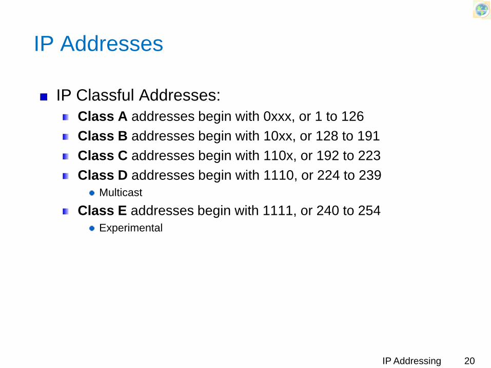
IP Classful Addresses:Class A addresses begin with 0xxx, or 1 to 126 Class B addresses begin with 10xx, or 128 to 191 Class C addresses begin with 110x, or 192 to 223 Class D addresses begin with 1110, or 224 to 239
Multicast
Class E addresses begin with 1111, or 240 to 254Experimental
20IP Addressing
Classful Addressing
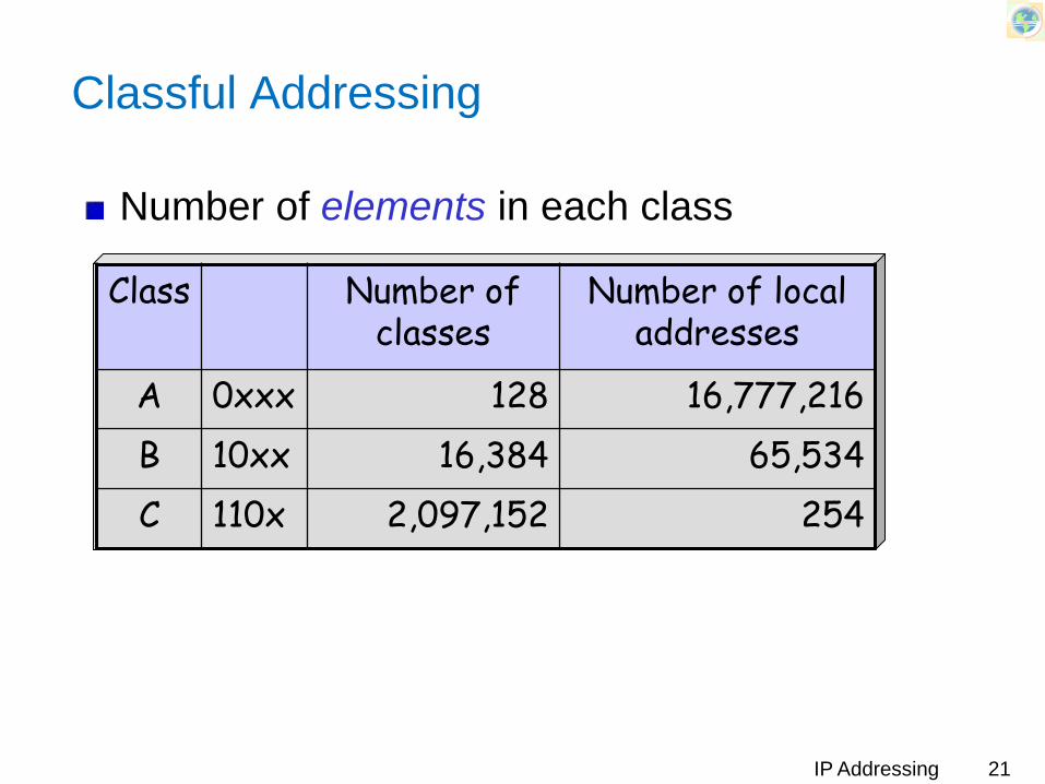
Number of elements in each class
Class Number of classes
Number of local addresses
A 0xxx 128 16,777,216B 10xx 16,384 65,534C 110x 2,097,152 254
21IP Addressing

Private IP Addresses Space
Private IP Networks Class of Network
Number of Networks
10.0.0.0 to 10.0.0.0 A 1172.16.0.0 to 172.31.0.0 B 16192.168.0.0 to 192.168.255.0 C 256
IP Addressing 22
Note: The third column is the Number of Networks (and not IP Addresses)
Problems with Classful Addressing
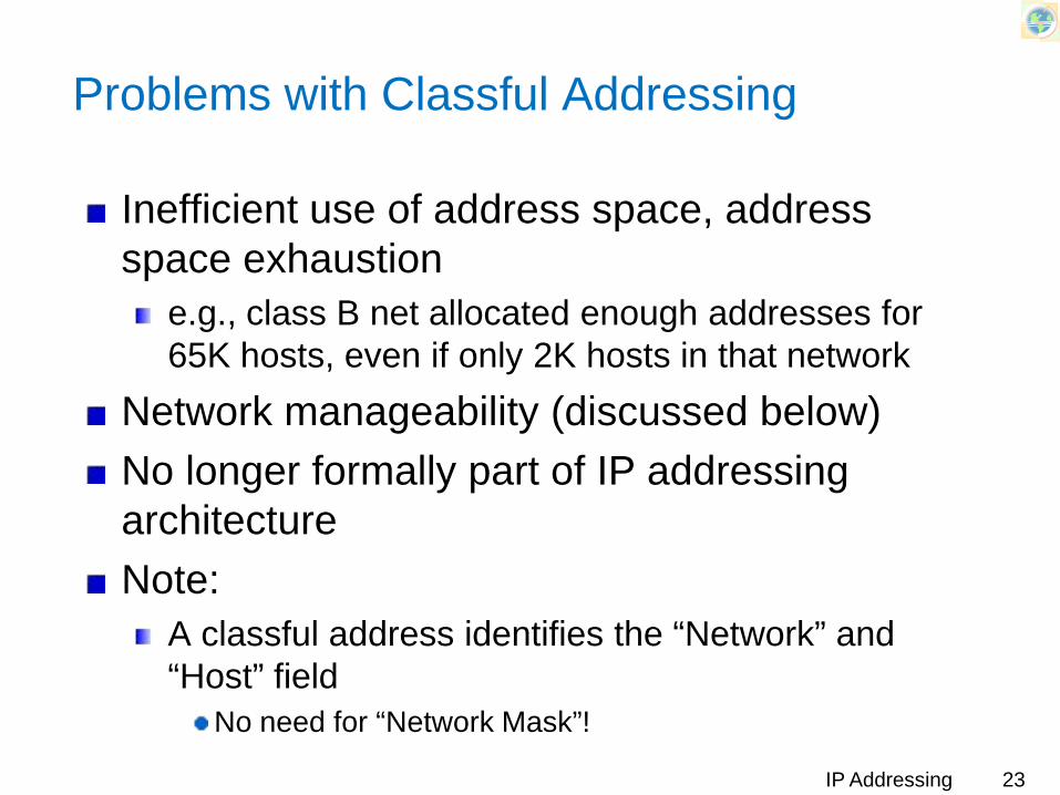
Inefficient use of address space, address space exhaustion
e.g., class B net allocated enough addresses for 65K hosts, even if only 2K hosts in that network
Network manageability (discussed below)No longer formally part of IP addressing architectureNote:
A classful address identifies the “Network” and “Host” field
No need for “Network Mask”!
23IP Addressing
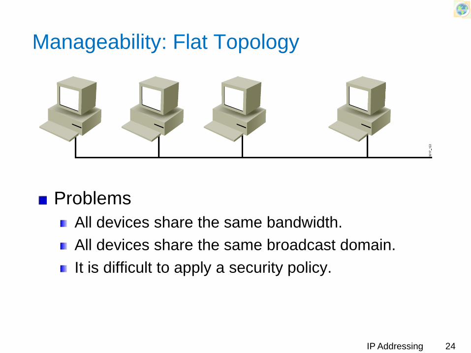
Manageability: Flat Topology
ProblemsAll devices share the same bandwidth.All devices share the same broadcast domain.It is difficult to apply a security policy.
24IP Addressing

Manageability: Subnetworks
The Smaller networks are easier to manage.Overall traffic is reduced.You can more easily apply network security policies.
1-25IP Addressing
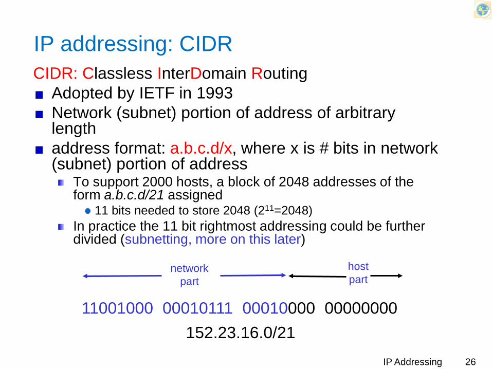
IP addressing: CIDRCIDR: Classless InterDomain Routing
Adopted by IETF in 1993Network (subnet) portion of address of arbitrary lengthaddress format: a.b.c.d/x, where x is # bits in network (subnet) portion of address
To support 2000 hosts, a block of 2048 addresses of the form a.b.c.d/21 assigned
11 bits needed to store 2048 (211=2048)In practice the 11 bit rightmost addressing could be further divided (subnetting, more on this later)
11001000 00010111 00010000 00000000
networkpart
hostpart
152.23.16.0/2126IP Addressing

Network Mask
With CIDR, address no longer specifies the network portionMask is used to extract network portion from an IP Address
A string of 32 bitsBits corresponding to network (and subnet) part set to ‘1’Bits corresponding to host part set to ‘0’Ex (classful address):
Addr = 9.2.225.65/8= 00001001.00000010.11100001.01000001
Mask = 11111111.00000000.00000000.00000000= 255 . 0 . 0 . 0
27IP Addressing

Mask examples (classful addresses)
Ex-1:Addr = 9 . 2 . 225 . 65/8
= 00001001.00000010.11100001.01000001Mask = 11111111.00000000.00000000.00000000
= 255 . 0 . 0 . 0N-Adr= 10001001.00000000.00000000.00000000
9.0.0.0
Ex-2Addr = 156 . 204 . 135 . 160/19
= 10011100.11001100.10000111.10100000Mask = 11111111.11111111.11100000.00000000
= 255 . 255 . 224 . 0N-Adr= 10011100.11001100.10000000.00000000
156 . 204 . 128 . 0
28IP Addressing
Two-Level and Three-Level Addresses
Inefficiency of two-level addressesA third level of addressing, consisting of subnets, was developedSubnet address: The original classful network portion plus a subnet field
Also known as extended network fieldSubnet and host field created from the original classful host portion
Subnet Mask helps identify the host/network part of an address
29IP Addressing

What a Subnet Mask Does
Tells the router the number of bits to look at when routingDefines the number of bits that are significantUsed as a measuring tool, not to hide anything
30IP Addressing
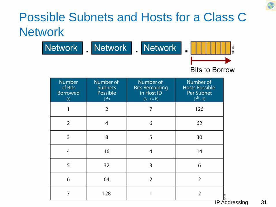
Possible Subnets and Hosts for a Class C Network
31IP Addressing

Possible Subnets and Hosts for a Class B Network
32IP Addressing

Possible Subnets and Hosts for a Class A Network
33IP Addressing
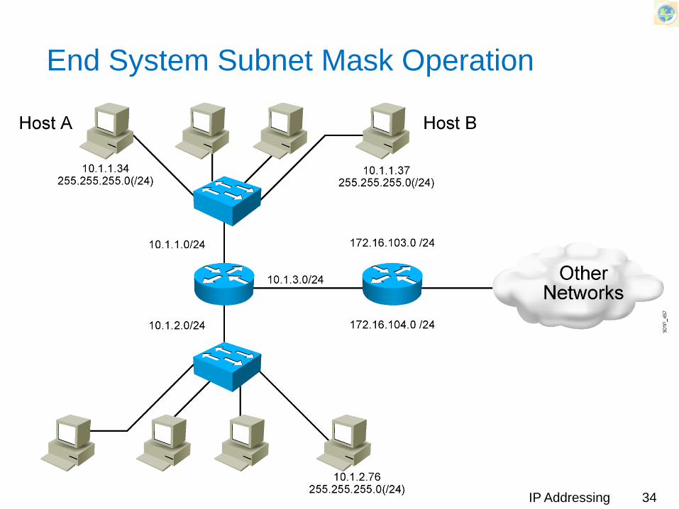
End System Subnet Mask Operation
34IP Addressing

Topology Example
A network topology using one IP network with six subnets
35IP Addressing

How Routers Use Subnet Masks
36IP Addressing

Working with subnets and masks: Analysis
Analysis of a given IP address/maskBinary/decimal maskSubnet number (network prefix)Next/previous subnetRange of addressesBroadcast addressThe first IP addressThe last IP addressImportant: are networks specified by 2 addresses overlapping?
IP Addressing 37

Working with subnets and masks: Design
Choosing a subnet mask to meet design requirements
Finding the only possible maskFinding multiple possible masksChoosing the mask that maximizes the number of subnets or hosts
IP Addressing 38

Subnet addresses
Reserved addresses:The smallest address (all “0”s) signifies the subnet number
128.12.17.144/28: x.y.z.1001000010.12.16.128/26: x.y.z.10000000
The last address (all “1”s) signifies the broadcast address
128.12.15.159/28: x.y.z.1001111110.12.16.191/26: x.y.z.10111111
IP Addressing 39
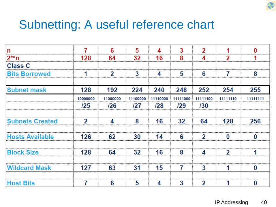
Subnetting: A useful reference chart
IP Addressing 40

Example: 199.214.17.132/28 (Class C)
IP@:x.y.z.10000100Borrowed bits: 4; Net bits: 28; Host bits: 4
Block size 16Mask(last byte only): 11110000; 240Subnet number: 199.214.17.128 (10000000)Next/previous subnets:
Next: 128 + 16= 144 (10010000)Previous: 128 – 16 = 112 (01110000)
Range of addresses: x.y.z.129 to x.y.z.143Broadcast address: 199.214.17.143First IP address: 199.214.17.129Last IP address: 199.214.17.142
IP Addressing 41
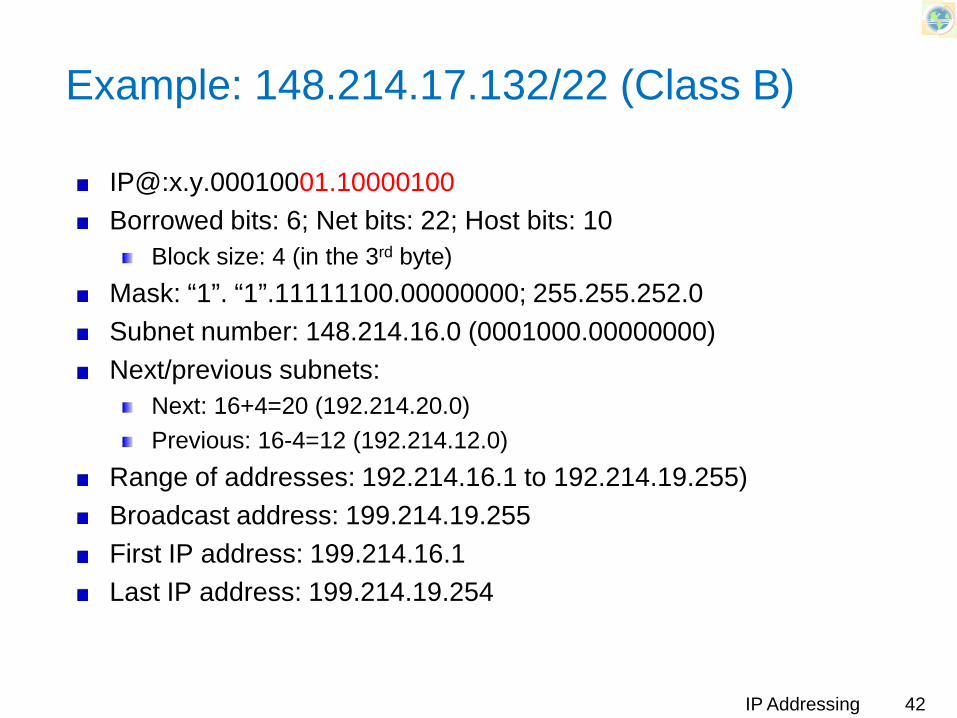
Example: 148.214.17.132/22 (Class B)
IP@:x.y.00010001.10000100Borrowed bits: 6; Net bits: 22; Host bits: 10
Block size: 4 (in the 3rd byte)Mask: “1”. “1”.11111100.00000000; 255.255.252.0Subnet number: 148.214.16.0 (0001000.00000000)Next/previous subnets:
Next: 16+4=20 (192.214.20.0)Previous: 16-4=12 (192.214.12.0)
Range of addresses: 192.214.16.1 to 192.214.19.255)Broadcast address: 199.214.19.255First IP address: 199.214.16.1Last IP address: 199.214.19.254
IP Addressing 42

Example: 9.214.17.132/12 (Class A)
IP@:Borrowed bits: __; Net bits: __; Host bits: __
Block size: __ (in the __ byte)Mask: Subnet number:Next/previous subnets:
Next:Previous:
Range of addresses:Broadcast address:First IP address:Last IP address:
IP Addressing 43

The Dread of Overlapping Subnets
In designing networks, care should be taken to prevent overlapping subnetsStep 1: calculate the subnet number and subnet broadcast address of each subnet.
Determines range of addresses within each subnet
Step 2: Compare the range of addresses in each subnet and look for any overlap
IP Addressing 44

The Dread of Overlapping Subnets
Is there any flaw in the following network?
IP Addressing 45

Problem Network
IP Addressing 46
172.16.4.2/23
172.16.5.2/24
172.16.2.1/23
1
2
3

The Dread of Overlapping Subnets
172.16.2.1/23Mask: 255.255.254.0 Subnet number: 172.16.2.0Broadcast @: 172.16.3.255
172.16.4.1/23Mask: 255.255.254.0Subnet number: 172.16.4.0Broadcast @: 172.16.5.255
172.16.5.1/24Mask: 255.255.255.0Subnet number: 172.16.5.0Broadcast @: 172.16.5.255
IP Addressing 47
Overlap!