Internet Time Synchronization: the Network Time Protocol · Abstract This memo describes the...
29
Abstract This memo describes the Network Time Protocol (NTP) designed to distribute time information in a large, diverse internet system operating at speeds from mundane to lightwave. It uses a returnable- time architecture in which a distributed subnet of time servers operating in a self-organizing, hierarchical, master-slave configuration synchronizes local clocks within the subnet and to national time standards via wire or radio. The servers can also redistribute time information within a network via local routing algorithms and time daemons. The architectures, algorithms and protocols which have evolved to NTP over several years of implementation and refinement are described in this paper. The synchronization subnet which has been in regular operation in the Internet for the last several years is described along with performance data which shows that timekeeping accuracy throughout most portions of the Internet can be ordinarily maintained to within a few tens of milliseconds, even in cases of failure or disruption of clocks, time servers or networks. This memo describes the Network Time Protocol, which is specified as an Internet Standard in RFC-1119. Distribution of this memo is unlimited. Keywords: network clock synchronization, standard time distribution, fault-tolerant architecture, maximum-likelihood estimation, disciplined oscillator, Internet protocol. Network Working Group D. L. Mills Request for Comments: 1129 University of Delaware October 1989 Internet Time Synchronization: the Network Time Protocol Mills Page i
Transcript of Internet Time Synchronization: the Network Time Protocol · Abstract This memo describes the...

Abstract
This memo describes the Network Time Protocol (NTP) designed to distribute time information ina large, diverse internet system operating at speeds from mundane to lightwave. It uses a returnable-time architecture in which a distributed subnet of time servers operating in a self-organizing,hierarchical, master-slave configuration synchronizes local clocks within the subnet and to nationaltime standards via wire or radio. The servers can also redistribute time information within a networkvia local routing algorithms and time daemons.
The architectures, algorithms and protocols which have evolved to NTP over several years ofimplementation and refinement are described in this paper. The synchronization subnet which hasbeen in regular operation in the Internet for the last several years is described along with performancedata which shows that timekeeping accuracy throughout most portions of the Internet can beordinarily maintained to within a few tens of milliseconds, even in cases of failure or disruption ofclocks, time servers or networks.
This memo describes the Network Time Protocol, which is specified as an Internet Standard inRFC-1119. Distribution of this memo is unlimited.
Keywords: network clock synchronization, standard time distribution, fault-tolerant architecture,maximum-likelihood estimation, disciplined oscillator, Internet protocol.
Network Working Group D. L. MillsRequest for Comments: 1129 University of Delaware
October 1989
Internet Time Synchronization:the Network Time Protocol
Mills Page i
Table of Contents
1. Introduction . . . . . . . . . . . . . . . . . . . . . . . . . . . . . . . . . . . . . . . . 11.1. Performance Requirements . . . . . . . . . . . . . . . . . . . . . . . . . . . . . . . . 21.2. Discussion of Approaches . . . . . . . . . . . . . . . . . . . . . . . . . . . . . . . . 32. Time Standards and Distribution . . . . . . . . . . . . . . . . . . . . . . . . . . . . . 43. Network Time Protocol . . . . . . . . . . . . . . . . . . . . . . . . . . . . . . . . . . 53.1. Implementation Model . . . . . . . . . . . . . . . . . . . . . . . . . . . . . . . . . . 73.1.1. Modes of Operation . . . . . . . . . . . . . . . . . . . . . . . . . . . . . . . . . . . 73.1.2. Data Formats . . . . . . . . . . . . . . . . . . . . . . . . . . . . . . . . . . . . . . . 83.1.3. State Variables . . . . . . . . . . . . . . . . . . . . . . . . . . . . . . . . . . . . . . 93.2. Procedures . . . . . . . . . . . . . . . . . . . . . . . . . . . . . . . . . . . . . . . 103.3. Robustness Issues . . . . . . . . . . . . . . . . . . . . . . . . . . . . . . . . . . . . 114. Sample Processing and Selection Operations . . . . . . . . . . . . . . . . . . . . . 134.1. Data Filtering . . . . . . . . . . . . . . . . . . . . . . . . . . . . . . . . . . . . . . 134.2. Peer Selection . . . . . . . . . . . . . . . . . . . . . . . . . . . . . . . . . . . . . . 165. Local Clock Design . . . . . . . . . . . . . . . . . . . . . . . . . . . . . . . . . . . 186. NTP in the Internet System . . . . . . . . . . . . . . . . . . . . . . . . . . . . . . . 216.1. Time Servers . . . . . . . . . . . . . . . . . . . . . . . . . . . . . . . . . . . . . . 216.2. Synchronization Subnet . . . . . . . . . . . . . . . . . . . . . . . . . . . . . . . . 216.3. Performance Analysis . . . . . . . . . . . . . . . . . . . . . . . . . . . . . . . . . 227. Future Directions . . . . . . . . . . . . . . . . . . . . . . . . . . . . . . . . . . . . 248. References . . . . . . . . . . . . . . . . . . . . . . . . . . . . . . . . . . . . . . . 25
List of Figures
Figure 1. Implementation Model . . . . . . . . . . . . . . . . . . . . . . . . . . . . . . . . . 6Figure 2. NTP Packet Header . . . . . . . . . . . . . . . . . . . . . . . . . . . . . . . . . . . 9Figure 3. Calculating Delay and Offset . . . . . . . . . . . . . . . . . . . . . . . . . . . . . 11Figure 4. Offset vs Delay . . . . . . . . . . . . . . . . . . . . . . . . . . . . . . . . . . . . 14Figure 5. Phase-Lock Loop Model . . . . . . . . . . . . . . . . . . . . . . . . . . . . . . . 18Figure 6. Raw Offsets . . . . . . . . . . . . . . . . . . . . . . . . . . . . . . . . . . . . . . 22Figure 7. Filtered Offsets . . . . . . . . . . . . . . . . . . . . . . . . . . . . . . . . . . . . 23Figure 8. Error Distribution . . . . . . . . . . . . . . . . . . . . . . . . . . . . . . . . . . . 23
List of Tables
Table 1. Outlyer Selection Procedure . . . . . . . . . . . . . . . . . . . . . . . . . . . . . . 17
RFC 1129 Network Time Synchronization October 1989
Mills Page ii

1. Introduction
How do hosts and gateways in a large, dispersed networking community know what time it is? Howaccurate are their clocks? In a recent survey involving 94,260 hosts and gateways of the Internetsystem [MIL89b], 20,758 provided local time using three time-transfer protocols. About half of thereplies had errors greater than two minutes, while ten percent had errors greater than four hours. Afew had errors over two weeks. Most local clocks are set by eyeball-and-wristwatch to within aminute or two and rarely checked after that. Many of these are maintained by some sort ofbattery-backed clock/calender device using a room-temperature crystal oscillator that may drift asmuch as a second per day and can go for weeks between manual corrections. For many applications,especially distributed internet applications, much greater accuracy and reliability is required.
Accurate, reliable time is necessary for financial and legal transactions, stocks and bonds trading,transportation reservation, dispatch and control, and many other applications involving widelydistributed resources. These applications often require multiple, concurrent, real-time access todatabases distributed over an internet of many networks. Internet time synchronization is necessaryfor reliable caching, archiving and transaction sequencing. Even the management functions of theinternet and its component networks need accurate time in order to manage control activation,monitoring coordination and significant event timestamping. Coordinated network time is extreme-ly useful when searching for elusive bugs and transients in day-to-day operations.
This paper presents an overview of the architecture, protocol and algorithms of the Network TimeProtocol (NTP) used in the Internet system to synchronize clocks and coordinate time distribution.The Internet consists of over 100,000 hosts on about 800 packet-switching networks interconnectedby a similar number of gateways. In this paper the capitalized Internet refers to this particular system,while the uncapitalized internet refers to any generic system of multiple networks interconnectedby gateways. While the backbone networks and gateways are carefully engineered for good service,operating speeds and service reliability vary considerably throughout the Internet. This places severedemands on NTP, which must deliver accurate and reliable time in spite of component failures,service disruptions and possibly mis-engineered implementations.
In the remainder of this introductory Section 1, issues in the requirements, approaches andcomparisons with previous work are discussed. The architecture of the NTP synchronization subnet,including the primary time references and distribution mechanisms, is described in Section 2. Anoverview of the NTP protocol is given in Section 3 and further intricacies in a formal specificationand implementation guide published elsewhere [MIL89a]. Section 4 describes the algorithms usedto improve the accuracy of delay and offset measurements made over statistically noisy internetpaths and to select the best clock from among a set of mutually suspicious clocks. Section 5 describesa local clock design based on a first-order, adaptive-parameter phase-lock loop and capable ofaccuracies to the order of a millisecond, even after extended periods when all synchronization pathsto primary reference sources have been lost. The international NTP synchronization subnet of timeservers and clients now operating on the Internet is described and its performance assessed in Section6. Further details on measured performance in the Internet can be found in [MIL89b]. Section 7discusses further development and issues for future research.
RFC 1129 Network Time Synchronization October 1989
Mills Page 1

1.1. Performance Requirements
In this paper to synchronize frequency means to adjust the clocks in the network to run at the samefrequency, while to synchronize time means to set the clocks so that all agree upon a particularepoch with respect to Coordinated Universal Time (UTC), as provided by national standards, andto synchronize clocks means to synchronize them in both frequency and time. A clock synchroniza-tion subnet operates by measuring clock offsets between the various time servers in the subnet andso is vulnerable to statistical delay variations on the various transmission paths. In the Internet thepaths involved can have wide variations in delay and reliability. The routing algorithms can selectlandline or satellite paths, public network or dedicated links or even suspend service without priornotice.
It should be noted that stable frequency synchronization in large subnets requires finely tunedtracking loops and multiple phase comparisons over relatively long periods of time, while reliabletime synchronization requires carefully engineered selection algorithms and the use of redundantresources and diverse transmission paths. For instance, while only a few comparisons are usuallyadequate to determine local time in the Internet to within a few tens of milliseconds, dozens ofmeasurements over many days are required to reliably resolve oscillator drift and stabilize frequencyto a few milliseconds per day [MIL89b].
Thus, the performance requirements of an internet-based time synchronization system are particular-ly demanding. A basic set of requirements must include the following:
1. The primary time reference source(s) must be synchronized to national standards by wire, radioor portable clock. The system of time servers and clients must deliver continuous local timebased on UTC, even when leap seconds are inserted in the UTC timescale.
2. The time servers must provide accurate and precise time, even with relatively large stochasticdelays on the transmission paths. This requires careful design of the data smoothing anddeglitching algorithms, as well as an extremely stable local clock oscillator and synchronizationmechanism.
3. The synchronization subnet must be reliable and survivable, even under unstable conditions andwhere connectivity may be lost for periods up to days. This requires redundant time servers anddiverse transmission paths, as well as a dynamically reconfigurable subnet architecture.
4. The synchronization protocol must operate continuously and provide update information at ratessufficient to compensate for the expected wander of the room-temperature crystal oscillatorsused in ordinary computer systems. It must operate efficiently with large numbers of time serversand clients in continuous-polled and procedure-call modes and in multicast and point-to-pointconfigurations.
5. The system must operate in existing internets including a spectrum of machines ranging frompersonal workstations to supercomputers, but make minimal demands on the operating systemand supporting services. Time-server software and especially client software must be easilyinstalled and configured.
RFC 1129 Network Time Synchronization October 1989
Mills Page 2

1.2. Discussion of Approaches
There are many ways that hosts distributed throughout a large geographic area can synchronizeclocks to UTC. In North America the U.S. and Canada operate broadcast radio services with a UTCtimecode modulation which can be decoded by suitable receivers [NBS79]. One approach to timesynchronization is to provide timecode receivers at every site where required. However, thesereceivers are specialized, moderately expensive and subject to occasional gross errors due topropagation and equipment failures.
The U.S. National Institute of Standards and Technology (NIST) (formerly National Bureau ofStandards), recently announced a computer time service available to the general public by meansof a standard telephone modem [NBS88]. The service is intended for use by personal workstationsto set clock-calenders, for example, but would not be suitable for a large population of clients callingon a frequent, regular basis without further redistribution.
In principle, it is possible to use special network facilities designed for time synchronization, suchas a dedicated FM or TV subcarrier or timecode rebroadcast by a cable system. For many yearsAT&T has synchronized digital switching equipment to the Basic Synchronization ReferenceFrequency (BSRF), which consists of a master oscillator synchronized to UTC and a network ofdedicated 2048-kHz links embedded in the transmission plant. AT&T and other carriers are planningto use the Global Positioning System and the LORAN-C radionavigation system to synchronizeswitches in various areas of the country to UTC. However, neither of these methods would beeconomically viable for widespread deployment in a large, diverse internet system.
Various mechanisms have been used in the Internet protocol suite to record and transmit the timeat which an event takes place, including the Daytime protocol [POS83a], Time protocol [POS83b],ICMP Timestamp message [DAR81a] and IP Timestamp option [SU81]. In the Hellospeak routingprotocol [MIL83b] one or more processes synchronize to an external reference source, such as atimecode receiver or time daemon, and the corrections are distributed via routing updates and aminimum-delay spanning tree rooted on these processes. The Unix 4.3bsd time daemon timed[GUS85a] uses an elected master host [GUS85b] to measure offsets of a number of slave hosts andsend periodic corrections to them.
Experimental results on measured times and delays in the Internet are discussed in [COL88],[MIL83a] and [MIL85b]. Other synchronization algorithms are discussed in [GUS84], [HAL84],[LAM78], [LAM85], [LUN84], [MAR85], [MIL85a], [MIL85b], [MIL89a], [RIC88], [SCH86],[SRI87] and [TRI86] and protocols based on them in [MIL81], [MIL85c], [MIL89a] and [TRI86].NTP uses techniques evolved from them and both linear systems and Byzantine agreementmethodologies. Linear methods for digital telephone network synchronization are summarized in[LIN80], while Byzantine methods for clock synchronization are summarized in [LAM85].
In an internet system involving many networks and gateways a useful approach is to equip a fewstrategically located time-server hosts (or gateways) with timecode receivers and coordinate timedistribution using a suitable internet protocol. However, the success of this approach requires veryaccurate and reliable mechanisms to process and distribute the time information, since timecode
RFC 1129 Network Time Synchronization October 1989
Mills Page 3

receivers, time servers and the internet itself cannot be considered wholly reliable. While reliableclock synchronization has been studied using agreement algorithms [LAM85], [SRI87], in practiceit is not possible to distinguish the truechimer clocks, which maintain timekeeping accuracy to apreviously published (and trusted) standard, from the falseticker clocks, which do not, on other thana statistical basis. In addition, the algorithms and protocols discussed in the literature do notnecessarily produce the most accurate time on a statistical basis and may produce unacceptablenetwork overheads and instabilities in a large, diverse internet system.
The above approach was used in the design of the NTP synchronization mechanisms, which wereevolved as the result of numerous experiments, analyses and stepwise refinements over an eight-yearperiod. It became evident that accurate and reliable internet time synchronization can be achievedonly through a integrated approach to system design including the primary reference sources, timeservers, synchronization subnet, protocols and synchronization mechanisms which are at the heartof this paper. From the analytical point of view the distributed system of NTP time servers operatesas a set of mutually coupled, phase-locked oscillators with phase comparisons exchanged by meansof update messages and a local clock at each time server functioning as a disciplined oscillator. Theprincipal features of this design, described in more detail later in this paper, can be summarized asfollows:
1. The synchronization subnet consists of a self-organizing, hierarchical network of time serversconfigured on the basis of estimated accuracy and reliability.
2. The synchronization protocol operates in connectionless mode in order to minimize latencies,simplify implementations and provide ubiquitous interworking.
3. The synchronization mechanism uses a returnable-time design which tolerates packet loss,duplication and misordering, together with filtering algorithms based on maximum-likelihoodprinciples.
4. The local clock design is based on a first-order, adaptive-parameter phase-lock loop withcorrections computed using timestamps exchanged along the arcs of the synchronization subnet.
5. Multiply redundant time servers and multiply diverse transmission paths are used in thesynchronization subnet, as well as engineered algorithms which select the most reliablesynchronization source and path using a weighted voting procedure.
6. System overhead is reduced through the use of dynamic control of polling rates and associationmanagement
2. Time Standards and Distribution
Since 1972 the time and frequency standards of the world have been based on International AtomicTime (TAI), which is currently maintained using multiple cesium-beam clocks to an accuracy of afew parts in 1012 [BLA74]. The Bureau International de l’Heure (BIH) uses astronomical observa-tions provided by the U.S. Naval Observatory and other observatories to determine corrections forsmall changes in the mean solar rotation period of the Earth, which results in Coordinated UniversalTime (UTC). UTC is presently decreasing relative to TAI at a fraction of a second per year, so
RFC 1129 Network Time Synchronization October 1989
Mills Page 4

corrections in the form of leap seconds must be inserted from time to time in order to maintainagreement. The U.S. and many other countries operate standard time and frequency broadcaststations covering most areas of the world, although only a few utilize a broadcast timecode suitablefor computer use. The U.S. and Canadian timecodes provide UTC time-of-day, day-of-year andrelated information, but not either the year or advance notice of leap seconds, which must bedetermined from other sources.
A synchronization subnet is a connected network of primary and secondary time servers, clientsand interconnecting transmission paths. A primary time server is directly synchronized to a primaryreference source, usually a timecode receiver. A secondary time server derives synchronization,possibly via other secondary servers, from a primary server over network paths possibly shared withother services. Under normal circumstances it is intended that the synchronization subnet of primaryand secondary servers assumes a hierarchical master-slave configuration with the primary serversat the root and secondary servers of decreasing accuracy at successive levels toward the leaves.
Following conventions established by the telephone industry, the accuracy of each time server isdefined by a number called the stratum, with the root level (primary servers) assigned as one andeach succeeding level towards the leaves (secondary servers) assigned as one greater than thepreceding level. Using existing stations, available timecode receivers with propagation-delaycorrections and allowing for sample accumulations up to a week or more, accuracies in the orderof a millisecond can be achieved at the network interface of a primary server [MIL89b]. As thestratum increases from one, the accuracies achievable will degrade depending on the network pathsand local clock stabilities. In order to avoid the tedious calculations [BRA80] necessary to estimateerrors in each specific configuration, it is useful to assume the measurement errors accumulateapproximately in proportion to the total roundtrip path delay to the root of the synchronizationsubnet, which is called the synchronizing distance.
Again drawing from the experience of the telephone industry, which learned such lessons atconsiderable cost, the synchronization subnet should be organized to produce the highest accuracy,but must never be allowed to form a loop, regardless of synchronizing distance. An additional factoris that each increment in stratum involves a potentially unreliable time server which introducesadditional measurement errors. The selection algorithm used in NTP uses a variant of the Bellman-Ford distributed routing algorithm [BER87] to compute the minimum-weight spanning trees rootedon the primary servers. With the foregoing factors in mind, the distance metric used by the algorithmwas chosen using the stratum number as the high-order bits and synchronizing distance as thelow-order bits.
3. Network Time Protocol
The Network Time Protocol (NTP) is used to construct and maintain a set of time servers andtransmission paths as a synchronization subnet. The protocol was first described in [MIL85c],extensively revised in successive versions and recently established as a formal Internet Standardprotocol [MIL89a]. NTP is built on the Internet Protocol (IP) [DAR81b] and User DatagramProtocol (UDP) [POS80], which provide a connectionless transport mechanism; however, it isreadily adaptable to other protocol suites. It is evolved from the Time Protocol [POS83b] and the
RFC 1129 Network Time Synchronization October 1989
Mills Page 5

ICMP Timestamp Message [DAR81a], but is specifically designed to maintain accuracy andreliability, even when used over typical Internet paths involving multiple gateways and unreliablenets.
There is no provision for peer discovery, acquisition, or authentication in NTP itself, although someimplementations include these features. Data integrity is provided by the IP and UDP checksums.No circuit-management, duplicate-detection or retransmission facilities are provided or necessary.The protocol can operate in several modes appropriate to different scenarios involving privateworkstations, public service machines and various network configurations. A lightweight associa-tion-management capability, including dynamic reachability and variable polling-rate mechanisms,is used to manage state information and reduce resource requirements. Optional features includemessage authentication based on crypto-checksums and provisions for remote control and monitor-ing. Since only a single NTP message format is used, the protocol is easily implemented and canbe used in a variety of operating-system and networking environments.
The following subsections contain an overview of the data formats, entities, state variables andprocedures used in NTP. Further details are contained in the formal specification. The specificationis based on the implementation model illustrated below, but it is not intended that this model be theonly one upon which a specification can be based. In particular, the specification is intended toillustrate and clarify the intrinsic operations of NTP and serve as a foundation for a more rigorous,comprehensive and verifiable specification.
In what may be the most common client/server modes a client sends an NTP message to one ormore time servers, which process the replies as received. A server interchanges addresses, overwritescertain fields in the message, recalculates the checksum and returns the message immediately.Information included in the NTP message allows the client to determine the server time with respectto local time and adjust the local clock accordingly. In addition, the message includes informationto calculate the expected timekeeping accuracy and reliability, so that inferior data can be discardedand only the best from possibly several servers can be selected. While the client/server modes maysuffice for use on LANs involving a public time server and perhaps many private workstation clients,
UpdateProcedure
ReceiveProcess
Local ClockProcess
TransmitProcess
Network
Figure 1. Implementation Model
RFC 1129 Network Time Synchronization October 1989
Mills Page 6

the full generality of NTP requires distributed participation of a number of client/servers or peersarranged in a dynamically reconfigurable, hierarchically distributed configuration. It also requiressophisticated algorithms for association management, data manipulation and local clock control asdescribed below.
3.1. Implementation Model
Figure 1 shows an implementation model for a time-server host including three processes sharinga partitioned data base, with a partition dedicated to each peer, and interconnected by a message-passing system. The transmit process, driven by independent timers for each peer, collects infor-mation in the data base and sends NTP messages to the peers. Each message contains the localtimestamp when the message is sent, together with previously received timestamps and otherinformation necessary to determine the hierarchy and manage the association. The messagetransmission rate is determined by the accuracy required of the local clock, as well as the estimatedaccuracies of its peers.
The receive process receives NTP messages and perhaps messages in other protocols, as well asinformation from directly connected timecode receivers. When a message is received the offsetbetween the peer clock and the local clock is computed and incorporated into the data base alongwith other information useful for error estimation and peer selection. A filtering algorithm describedin Section 4 improves the estimates by discarding inferior data.
The update procedure is initiated upon receipt of a message and at other times. It processes the offsetdata from each peer and selects the best one using the selection algorithm of Section 4. This mayinvolve many observations of a few peers or a few observations of many peers, depending on theaccuracies required.
The local-clock process operates upon the offset data produced by the update algorithm and adjuststhe phase and frequency of the local clock using the mechanism described in Section 5. This mayresult in either a step change or a gradual slew adjustment of the local clock to reduce the offset tozero. The local clock provides a stable source of time information to other users of the system andfor subsequent reference by NTP itself.
3.1.1. Modes of Operation
An NTP association is formed when two peers exchange messages and one or both of them createand maintain an instantiation of the protocol machine. The machine can operate in one of five modes:symmetric active, symmetric passive, client, server and broadcast. When an association is formedone or both peers must be operating in an active mode (symmetric active, client or broadcast), inwhich the active peer sends messages to the other peer regardless of the mode, reachability state orstratum of the other peer. If due to crash restart or defective programming both peers are found tobe operating in a passive mode (symmetric passive or server), each peer ignores the messages ofthe other, so that eventually each will find the other unreachable and demobilize the association. Insymmetric passive and server modes the identity of the other peer need not be known in advance,since an association with persistent state variables is created only when an NTP message arrives.
RFC 1129 Network Time Synchronization October 1989
Mills Page 7

Furthermore, the state storage can be reused when the peer becomes unreachable or begins operatingat a higher stratum and thus ineligible as a synchronization source.
The symmetric modes are intended for distributed scenarios where either peer can potentiallybecome the reference source for the other. By operating in these modes a host announces itswillingness to synchronize to and be synchronized by the peer. Symmetric active mode is designedfor use by hosts operating near the leaves (high stratum levels) of the synchronization subnet, whilesymmetric passive mode is designed for use by hosts operating near the root (low stratum levels)and with a relatively large number of peers on an intermittent basis. Reliable time service can usuallybe maintained with two peers at the next lower stratum level and one peer at the same stratum level,so the rate of ongoing polls is usually not significant, even when connectivity is lost and errormessages are being returned from the network for every poll.
Broadcast mode is intended for operation with high speed LANs and numerous workstations wherethe highest accuracies are not required. In the typical scenario one or more LAN time-server hostssend periodic NTP messages to the LAN broadcast address. The LAN workstations then determinethe time on the basis of a preconfigured latency in the order of a few milliseconds. By operating inthis mode the host announces its willingness to provide synchronization to the peers, but not toaccept NTP messages from them.
The client and server modes are intended for operation with file servers and workstations requiringthe highest accuracies or where broadcast mode is unavailable or inappropriate. A host operatingin client mode sends periodic NTP messages to one or more servers. By operating in this mode thehost announces its willingness to be synchronized by, but not to provide synchronization to the peer.A host operating in server mode simply interchanges the source and destination addresses/ports,fills in the requested timestamps and returns the message to the client. Hosts operating in servermode need retain no state information between client requests, while clients are free to manage theintervals between messages to suit local conditions. By operating in this mode the host announcesits willingness to provide synchronization to, but not to be synchronized by the peer.
3.1.2. Data Formats
All mathematical operations assumed in the protocol are two’s-complement arithmetic with integeror fixed-point operands. Since NTP timestamps are cherished data and, in fact, represent the mainproduct of the protocol, a special format has been established. An NTP timestamp is a 64-bitunsigned fixed-point number, with the integer part in the first 32 bits and the fraction part in the last32 bits and interpreted in standard seconds relative to UTC. When UTC began at zero hours on 1January 1972 the NTP clock was set to 2,272,060,800.0, representing the number of standardseconds since this time on 1 January 1900 (assuming no prior leap seconds).
This format allows convenient multiple-precision arithmetic and conversion to other formats usedby various protocols of the Internet suite. The precision of this representation is about 232picoseconds, which should be adequate for even the most exotic requirements. Note that since sometime in 1968 the most significant bit of the 64-bit field has been set and that the field will overflowsome time in 2036. Should NTP be in use in 2036, some external means will be necessary to qualify
RFC 1129 Network Time Synchronization October 1989
Mills Page 8

time relative to 1900 and subsequent 136-year cycles. Timestamped data requiring such qualifica-tion will be so precious that appropriate means should be readily available.
Timestamps are determined by copying the current value of the local clock to a timestamp variablewhen some significant event occurs, such as the arrival of a message. In some cases a particularvariable may not be available, such as when the host is rebooted or the protocol first starts up. Inthese cases the 64-bit field is set to zero, indicating the value is invalid or undefined. There willexist an 232-picosecond interval, henceforth ignored, every 136 years when the 64-bit field willnaturally become zero and thus be considered invalid.
3.1.3. State Variables
Following is a summary description of the important variables and parameters used by the protocol.In appropriate modes a set of state variables is maintained for the host itself along with separatecopies for each peer with an active association. Further information on these variables is given laterin this paper. A complete description is given in [MIL89a].
Figure 2 shows the NTP packet-header format, which ordinarily follows the IP and UDP headers.Following is a description of the various fields.
Version Number (VN). Identifies the present NTP version.
Leap Indicator (LI). Warns of an impending leap second to be inserted or deleted in the timescaleat the end of the current day.
Mode, Stratum, Precision. Indicate the current operating mode, stratum and precision.
LI VN Mode Precision
Synchronizing Distance
Poll IntStratum
Synchronizing Dispersion
Reference Timestamp (64 bits)
Reference Timestamp (64 bits)
Originate Timestamp (64 bits)
Receive Timestamp (64 bits)
Authenticator (optional) (96 bits)
Figure 2. NTP Packet Header
RFC 1129 Network Time Synchronization October 1989
Mills Page 9

Poll Interval. Controls the intervals between NTP messages sent by the host to a peer. The sendinghost always uses the minimum of its own poll interval and the peer poll interval.
Synchronizing Distance, Synchronizing Dispersion. Indicate the estimated roundtrip delay andestimated sample dispersion, respectively, to the primary reference source.
Reference Clock Identifier, Reference Timestamp. Identify the reference clock and the time of itslast update, intended primarily for management functions.
Originate Timestamp. The time when the last received NTP message was originated, copied fromits transmit timestamp field upon arrival.
Receive Timestamp. The local time when the latest NTP message was received.
Transmit Timestamp. The local time when the latest NTP message was transmitted.
Authenticator (optional). The key identifier and encrypted checksum of the message contents.
The NTP protocol machine maintains state variables for each of the above quantities and, in addition,other state variables, including the following:
Addresses and Ports. The 32-bit Internet addresses and 16-bit port numbers of the host and its peers,which serve to identify the association.
Peer Timer. A counter used to control the intervals between transmitted NTP messages.
Reachability Register. A shift register used to determine the reachability status of the peer.
Filter Register. A shift register where each stage stores a tuple consisting of the measured delay andoffset associated with a single observation.
Delay Estimate, Offset Estimate, Dispersion Estimate. Indicate the current estimated roundtripdelay, clock offset and dispersion produced by the filter procedure.
Clock Source. A selector identifying the current clock source determined by the selection procedure.
Local Clock. The current local time as derived from the host logical clock.
3.2. Procedures
The significant events of interest in NTP occur upon expiration of a peer timer, one of which isdedicated to each peer with an active association, and upon arrival of an NTP message from thevarious peers. An event can also occur as the result of an operator command or detected systemfault, such as a primary clock failure. This subsection describes the procedures invoked when theseevents occur.
The transmit procedure is called when a peer timer decrements to zero and can occur in all modesexcept server mode. When this occurs the peer timer is reset and an NTP message is sent includingthe addresses, variables and timestamps described above. The value used to reset the timer is calledthe polling interval and is adjusted dynamically to reflect network peer path conditions.
RFC 1129 Network Time Synchronization October 1989
Mills Page 10

The receive procedure is called upon arrival of an NTP message, which is then matched with thepeer association indicated by its addresses and ports. If there is no match a new instantiation of theprotocol machine is created and the peer association mobilized. Following a set of sanity checksthe roundtrip delay and clock offset relative to the peer are calculated as follows. Number the timesof sending and receiving NTP messages as shown in Figure 3 and let i be an even integer. Then ti-3,ti-2, ti-1 and ti are the message arrival and departure timestamps in the order shown and the roundtripdelay di and clock offset ci of the peer relative to the host are computed as follows:
di = (ti – ti-3) – (ti-1 – ti-2),ci = [(ti-2 – ti-3) + (ti-1 – ti)]/2.
This method amounts to a continuously sampled, returnable-time system, which is used in somedigital telephone networks. Among the advantages are that the order and timing of the messagesare unimportant and that reliable delivery is not required.
The offset ci is then checked for validity relative to the estimated maximum skew and stated precisionof the host and peer clocks. The filter procedure is called with ci and di as arguments to produce theestimated delay, offset and dispersion for the peer involved. The minimum-filter algorithm describedin Section 4 is used to improve these estimates depending upon the statistical properties of theoutbound and inbound transmission paths.
The update procedure is called when a new delay/offset estimate becomes available. A weightedvoting procedure described in Section 4 determines the best peer, which may result in a new clocksource. If the clock source is the peer involved, the estimated offset is used to update the local clockas described in Section 5. If the local clock is reset, rather than gradually slewed to its final value,the clear procedure is called repeatedly for every active peer to purge the clock filter, reset the pollinginterval and reselect the clock source, if necessary. A new selection will occur when the filters fillup again and the dispersions settle down.
3.3. Robustness Issues
It has been the experience of the Internet community that something somewhere in the system isalways broken at any given time. This caveat applies to timecode receivers, time servers andsynchronization paths, any of which can misbehave to produce a bogus timestamp popularly knownas a timewarp. The very nature of time synchronization requires that it be extremely robust againsttimewarps and capable of operation even when major breakdowns or attempted breakins occur. This
t2
t3
t6
t7
t1
t4
t5
t8
PeerHost
Figure 3. Calculating Delay and Offset
RFC 1129 Network Time Synchronization October 1989
Mills Page 11

subsection describes some of the measures taken to deal with these problems, including reachabilitydetermination, authentication, sequence checking and polling rates.
As shown previously, reliable time synchronization does not require reliable message delivery;however, in order to minimize resource requirements, resist using very old data and manage thenumber of associations required, a simple reachability protocol is used. Each time an NTP messageis sent an eight-bit reachability register is shifted one position to the left and the low-order positionset to zero. If an NTP message is received before the next message is sent, the low-order bit is setto one. The peer is considered reachable if the register is nonzero, which will always be the case ifat least one message is received during eight consecutive transmit intervals. In the passive modesif a peer becomes unreachable, the association is demobilized and its resources reclaimed forsubsequent associations. This shift-register mechanism has also been found most effective in otherInternet protocols designed to survive unstable network service.
While not a required feature of NTP itself, some implementations have included an access-controlfeature that prevents unauthorized access and controls which peers are allowed to update the localclock. This is done with tables of mask-and-match entries which allow only servers with Internetaddresses in certain ranges to become peers and to update the local clock. In principle, this featureis not necessarily desirable, since the basic NTP design involving a large degree of diversity isintended to cast out falsetickers whether they are authenticated or not. Nevertheless, the additionalauthentication feature may help to deflect multiple-peer destructive jamming.
During the course of normal operation various peers may on occasion restart the NTP program itself,either due to loss of reachability, reboot or other trauma, which results in loss of state information.Special sanity checks are built into the receive procedure to avoid disruption in such cases. Onecheck requires the transmit timestamp of a received message to be different than the transmittimestamp of the last message received. If they are the same, the message is a duplicate and musthave been circulating in the network for some time after the last message was received, thuscontaining relatively inferior data. Another check requires the originate timestamp of a receivedmessage to be identical to the transmit timestamp of the last message transmitted. If they do notmatch, the message is either out of order, from a previous association or bogus. Additional checksprotect against using very old time information and from associations not completely synchronized.
Where security considerations require the highest level of protection against message modification,replay and other overt attacks, the NTP specification includes optional cryptographic authenticationprocedures. The procedures are used to insure an unbroken chain of authenticated peers along thesynchronization subnet to the primary servers. An authenticator, consisting of a key identifier andencrypted checksum, is computed using the DES encryption algorithm and DES cipher block-chain-ing method. Present implementations have incorporated special provisions to avoid degradation intimekeeping accuracy due to the delays caused by the encryption computations.
Careful consideration was given during design to factors affecting network overheads. Many of thepresent Internet primary time servers operate with 100 peers or more and some operate with manymore than that. Therefore, it is important that the longest polling intervals consistent with therequired accuracy and reliability be used. When reachability is first confirmed and when a peer is
RFC 1129 Network Time Synchronization October 1989
Mills Page 12

currently selected for synchronization it is necessary to use a relatively short polling interval in theorder of a minute. In those cases where the association has stabilized, the dispersions are low andthe peer is not selected for synchronization, the polling interval can be increased substantially. Inthe present design the polling interval is increased gradually from about one minute to about 17minutes as long as the dispersion is below an experimentally determined threshold; otherwise, it isdecreased gradually to the initial value. These values may change as the result of further experience.
4. Sample Processing and Selection Operations
At the very heart of the NTP design are the algorithms used to improve the accuracy of the estimatedoffsets and delays between the host and its various peers, as well as those used to select a particularpeer for synchronization. The complexity of these algorithms depends on the statistical propertiesof the transmission path and the accuracies required. In the case of LANs operating at megabitspeeds and above the path delays are usually smaller than the required accuracies, so the raw offsetsdelivered by the receive procedure can often be used directly to adjust the local clock. However, inthe case of paths involving many network hops via regional and backbone networks such asNSFNET, the path delays and delay variances can be much larger than acceptable without furtherprocessing.
Since Internet paths often involve multiple hops over networks of widely varying characteristics, itis not possible to design one set of algorithms optimized for a particular path. Therefore, thedevelopment of algorithms appropriate for ubiquitous Internet application has involved a processof stepwise refinement, beginning with the designs suggested in [MIL85a], refined as the results ofexperiments described in [MIL85b] and [MIL89b] and evolved over several years of operation underwidely varying conditions of path qualities and reliabilities. In following subsections the issues,approaches and designs of these algorithms are discussed.
4.1. Data Filtering
A number of algorithms for deglitching and filtering time-offset data have been described pre-viously, such as in [MIL85a], [HAL84] and [KOP87]. These fall in two classes: majority-subsetalgorithms, which attempt to separate good subsets from bad by comparing statistics such as meanand variance, and clustering algorithms, which attempt to improve the estimate by repeatedly castingout outlyers. The former class was suggested as a technique to select the best (i.e., the most reliable)clocks from a population, while the latter class was suggested as a technique to improve the offsetestimate for a single clock given a series of observations.
After further development and experimentation using typical Internet paths, a better algorithm wasfound for casting out outlyers from a continuous stream of offset observations spaced at intervalsin the order of minutes. The algorithm can be described as a variant of a median filter, in which awindow consisting of the last n sample offsets is continuously updated and the median sampleselected as the estimate. However, in the modified algorithm the outlyer (sample furthest from themedian) is then discarded and the entire process repeated until only a single sample offset is left,which is then produced as the offset estimate. This algorithm was found to be more resistant to
RFC 1129 Network Time Synchronization October 1989
Mills Page 13

glitches and to provide a more accurate estimate than the unmodified one. It was used in the Fuzzballand Unix implementations for about two years until the end of 1987.
Recent experiments have demonstrated an even better algorithm which provides higher accuracytogether with a lower computational burden. The key to the new algorithm became evident throughan examination of scatter diagrams plotting clock offset versus roundtrip delay. Recall that theroundtrip delay di and clock offset ci are computed from the four most recently observed timestamps.Without making any assumptions about the delay distributions due to queueing delays for traffic ineither direction along the path, but assuming the intrinsic frequency offsets of the host and peerclocks are relatively small, let d0 and c0 represent the delay and offset when no other traffic is presenton the path and so represents the true values. The problem is to accurately estimate d0 and c0 froma sample population of di and ci collected over a relatively long period.
Figure 4 shows a typical scatter diagram in which the points (di,ci) are concentrated near the apexof a wedge defined by lines extending from the apex with slopes +0.5 and -0.5, corresponding tothe locus of points as the delay in one direction increases while the delay in the other direction doesnot. From these data it is obvious that good estimators for (d0,c0) would be points near the apex.
Upon reflection, the reason for the particular distribution of points in the scatter diagram can beexplained as follows. Packet-switching nets are most often operated well below the knee of thethroughput-delay curve, which means the busy periods are relatively short and infrequent. Inaddition, the routing algorithm most often operates to minimize the number of packet-switch hopsand thus the number of queues. Thus, not only is the probability that an arriving NTP packet findsa busy queue in one direction relatively low, but the probability of packets from a single exchangefinding busy queues in both directions is even lower.
· ··
·
· ·
···
··
· ·····
···· ···
· ·····
·· ·
·
·
····
·
·· ···
·
·· ···
·· · ····
····
··
···· · ··
· ····
··
··
·
··
· ··· ·
·
·· ·· ·· ·· ······
·· ·· ···
· ···
···
·· ·····
··
·
· · ···
·
·· ··
·
·
·
·
··
·
·
·
· ··· ···
···
·· ··
·
··
· ···· ····· · ··· ··· ·
·
· ·
·
· · ···
······· ·· · ··
·
·····
·· ···
· ·· ·· ·· ·
··· ···
·· ·· ···· ···· ·· ·
·
·· ·· ··· ·· ···· ·· ·· ···· · ··
·· ·· ······ ···
··· ·· ··
···
· ···
··· · ·· ···
···· ·······
··· ··· ···
·· · · ··· · ··· · · ··· ··· · ··· ···· ··· ·
··· ·
······ · ···· ·· ······· ·· ·· ···· ·· ·· ···
··· ·····
·· ···· ···
·
·· ·
·
· ·····
·· ····· ····· · ······ ·
·· ·· ··
···· ··
· ······· ·· ·· ···· ······
·
·
··· ··
·
··· ···· ···· ·· ···· · ·· ·
····
·
·· · ··· ·· ·· ····· ··· ·· · ····· ········· ·· ··· ·· ·· ··
· ······ ···· ···
· ···
· · ·· ·· ·· ····
··
·· ······· ···· ··
·
·· ····· ···· ···· ··· ·· ·
·
··
···· ···· · ·
······ ·· · ··· ··· ·· ···· ··
·· ··
··· · ··
···· ·· ·
··· ·· · ·
·· ·······
·
·· ·· · ·· ····
··············· ·· ··
········ ·· · · ····
··· ··
···
·
·
·
···· ······ ·· ·· ··· ···
·· ··· ·· ·· ·· ··· ··· ··· ··· ·· ·· · ·· ····
··· ·
· ·
·· ····
·· ····· · ···· ··
·
· ······ · ······
· ·· · · ······· ···
···
·
··· ···
···
·
·
·
···· ···
··· ·· ··· ·· ·
···· ··· ···· ·
··· ····· ·· ·
·
·
·
···
···
····· ··· ··· ··· · ·
·
···
·
·· · ····
· ···
··
··
· ··· ·· ··
··· ··
····· ·· ··
·
··
· · ·· ·· ····· · ·· ···· ···
·
····
· ··· ·
·· ··
·····
· ·· · ·· ·· ·····
··
·
·
··
·
··
····· ···
·
·
·
····
· ·······
··
····
·· ·· · · ··
·· ·
·· ·· ··· ·· ··· ····
···
··
··· ·· ··
····
·
···
····· ···· ·· ··· ··· ··
·· · ·
···· ···
··
··· ··· ··
·
··
··· ··· ··· ·· ···· ·
·· ·· · ··
·
·· ·
·
··
· ·
·
·· ··
··· ··· ···· ··· ·
·· ···
·· ·
·· ··· ···· ··
·· ····· ····
···· ·· · ··· · ···
·· ·· ·
·
·
··· ··
··
·· ··
··· ··
·· ··
··
·· ········
·····
··· ····
····· ·· ·· ·· ·· ··· ·· ··· ·· ·
···
· ····
·
·······
· ···· ···· ··· · ·
·
·····
· · ··
·· ·· ······
·· ·· ····
··
·
··
·
··
··
·
·
· ··· ···· ··· ·· ··
··
···
····· ··· ··
······
· ··
··
·· ····
· ·· ···
·
·· ·· ·· ·· ·· ··· ·· ··· ··
·· · · ·
· ·····
· ··
· ·· ·· ·· · ···
····· ····
·
·· · · ···
·
··· ······ ······· ·
···· ·· ·· ···· · ···
· ··· ·· ·
·
··
···· · ·· ···
·· ·· ·······
··
·· ·· ·· ·· ··· ···· ···
····· ··· ··· ·· ···· ·· ··· · ·
··
· ·· · · ···· ·· ·· ···· · ··
·· ··· ·
·· ·· ··
·
· ···· ········ · ·
··· ··· ··
··
···
··
·
·····
·····
·· ···· · ··· · ····
··· · ·· ··· ····· · ·
··
·····
·· · ··
· ··· ··
·
··
·· ····
·· ·· ····· ·· ·· ·····
··· ·· ·· ····
······ · ·
·····
·· ·· ···· ···· ···· ·· ·· ··· ···· ·
··· ··· · ·· ····· ····
·····
·· · ···· ··· ···· ···· ··· ···
········· · ··· ·
··
·· ·· ····
······· ·· ·
·····
··
···· · ···· ··· ·· · ··· ·· ···
·· · ·
··
··
········· ·· ·
·
· ·· ··
·· ·· ··
····· ·· ·· · ··· ···· ··· ··
······ ···· ·
····· · · ··· ··
· · ·· ·· · · ···
··
··
· ·· ·· ·· ····
· ··· ·
·· ··
··
·· · ·· ··
· ·· ·· ·· ···· ···· ·· ·· ···
··
····· ·· ··
·· ·····
··
·
··
··
···
···· ·· ··
·· ·
·
· · · ·· ···
··· · ·· ·····
··
·· ··· ··· ·
· ·
·· ·
······
·· ·
··
· · ···· ·
·· ···· ····
··· ···· ·
·· ·· ·· · ··
··
··· ··
· ·· ·· ··
· ·· ···· ·· ·· ·· ··· ·· ··
···
·
· ··· ··· ·· ··· ····· ·
··
·· ··· ··
·
·· ·· ··
·
···
· ·· ···· · ··
·
· ·
·
·
· ·· ·······
· ·· ··
··
··· ···· ·
···
··· ··
· ·
·
· ·· ··
·
··· ····· ·
··· ··
·
········ ·· ······· ·
·
·
··
· ···
·····
··· ···· ·····
··
·· ·· ·
····· · ·· ··· ·· ·
······· ·· ·· ········ · ·
····· ·· ··
···
· ·· ··
· ·· · ·
·
··
···
····
···· ···· ·
··
· ··
·
·
··
··
· · ···
·· ···
····
··· ··· · ··
·· · · ···· ·· ···
· ·· ·
·· ·· ··· ·· ····· ··· ·· ··
··
·· ·· ···· ·
··
······
·
····· ··· · ··· ··· ·· ·· ···
·
··
·· ····
·· ·
··
·· ···
·· · ··
·· ··· ··
·
··
·· ·· ··· ···· ·· ··· ··· ·· ··
··· ·· ··· ··· ·· ······ · ·· ···
··
·· · ···
· ···· ···· ······ ····
···· · ·· ··
·· ··· ·· ··
· ·· ······· ·
··· ·· ···· ····· · · · ·· ···· ·····
·
···
·· ·· ······· ·· ···
····
··· ··· ··· ··· ··
·
···· ·· · ··· ·· · ··· ···
· ····· ··· ··· · · ···· ·
·
···· ·· ·· ·· ··
··· ··· ·
···
·· ··· · ·· ········· ··· ··
·
···
·· ·
·
···
·· ········ · ··· ···
··
·· ·······
·····
·· ··
····· ···
·
· ···· ·· · ···
·····
·· ··· ···
·· ·· ··· ·· ·· ··· ·· ·· ·· ··· · ····· · ···
····· ··
······· ··· ·· ····· · ····
··· ·· ····
·· ······· ·· ·· ···· · ·
··
·
···· ···· ··· ·····
·· ·· ··· · ·
·····
··· ··· ·
··· ····
······· ··· ·
·· · · ····· ··· ·
··
··· ··· · ··· ·· ·· ····· ··
·····
· · ···
· ····· ············ ·· ·· · ··· ····
·· ···· ····· ······ ··· ·· ·· ·· ··· ···· ·· · ·····
··
·· ·· ·
············
·
···
·
···· ···· · ···
···· ·
·· ·· ·
···· ···
·
· ·· · ··· ·· · ··· ··
·· ··· ·
·
····
· ··· ··· ··· · ··· ··· ·
·
· ··· ·· ·· ···· ··
··
· ···· ·· ··
·
··
·· ···
·
···
·
· ····
· · ···
·
·
···
·
··
·· ··
· · ···
··
· ··
·· ·· ··· ··
·
· ···· ·
··· ·
··· · ·· ·· ··
·· ·
··· · ·· ·
· ······ ··
··
·· ····
·· ·
· ··
···· ·
··
·· · ·
·
· ·· ···· ···
·· · ··· ·· ···
··
·
··
·
·········
·· ·· ·· · ··· ·· ·· · ··
··
·
· ··
·
··
·
·
·
· ·
·· ··
··
··· ·· ·· ·· ······
·· ·
··· ···
··
·
·· ···
· ··
·· ···· ·· ··
·
·
··
· ·· ··· · ··
·
· · ······
· ··
····
· ·· · ··
···
·
···
·
·· ····· ·
·
·· ··
·
··
·
·· ·· · ·· ··
·
···· · ··
·
·
· ·
·
··
··· ··· ··
··
··· ·· ··
·
·· ···
··
·· · ···· · ··
·
·· ··
·
·
·
·· · ···
·
·
···
····· ··
·· ····· ·
·
·· ·· · ······ · · ······ · ·
··· ··
··
···
·· ·· ··· ·· ··· ·
··· ·· ··· ··
· ··
···
·
·
·· ········· ··
·
·· ··
·
·· ···
·
·· ··
·
··· ····
· ······
··· ··
· ·· ·
·· ·· ·
···
··
·
··· ······· ··
·
··
··
·
·
··
· ··
·
·
·
· ····
·
·
· ·
·
· ··
· ·· ··· · ····
·
···· ·
· ·· ·· ·
·
· ··
·· · ·· ·· ·· ······
·
··
·· ·· ···· ·· ····· ··· ·· ····· ··· ·
·· ··· ···· ···· ······· ··· ·· ·
·
······
·
·
·· · ·· ···
··
··
· · ··· ···
···
·· · · ··
····
··
·
··· ·· ·
·· · · ····
······ · ··
·····
· ·· ··
··
· ····· ·
·
· ·· · ·· · ······ ····· ·· · ·
·
···
·· ·· ··
·
··· ·····
·
···
·
·
· ····
···
· ··· · · ··· · ··
·· ·· ·····
·· ·· ·
· ·· ·· ···· ·
·
·· ·
·
·· ·· · ·· ·· ·· ·· ·
·
···
····· ··· ····· ··· ·
·
··
·· · ·· ···· ····· ·· ·· ···· ·· · ··
··
··· · ·· ·
·
· ·
·
···· ·· ···
·
······
······ ···· ··· ····
·· ···· · ·· ·
··
·
··· · ·· · ·
·· ······ ·
····· ······· ······ ··
·
····· ···
· ·· ··
· ······· ·· ·· ····
····
····· · ··
·
· ·· · ··
···
·
···
·
··
··
·
· ····
· ·· ·········
···
·· ·
······· ···
······ · ·
·
·· ·· ··
·· ···· ·· ··
·
·
· ···· ···
·· · ··· · ·· ·
······ · ····
··
··
· ···· ·· ·····
···
··
···
· ··· ·
·
··
·
···
·
···
· ···
··
·· ··
···· · ·
··
·
· ·· ·
·
···
······
·
··
· ·· ····
···
··· ··
·
·· ·
··
·
· ·
·
··
·
····
·
·· ··· ···· ·· ··
· ··
·
· ·· ···
·
··
· ··
····
·· · ··· ·· ·· ·· ···
··
··
·
· ···
·· · ··
··· ·
·· ··
· ··
·· ···
·
··
··
·· ··· ··
·
·
··
· ·· ·· ····
·
··
···· ······
···· ·· · ··· ··· ····· · ·· ·· ····· ·· ·
··· ·· ·· · ·
·
·
·
···
·
·
··
···
· ···
···· ·· ·· ·
····· · ··· · ·
·· ·· ·
····
···
···
··· ·· ····
·
·
··
·
· ·····
· ······
···· ·· ········· ··· ··
··
·· ··
··
··
·
···
·
·
· · ··· ···· ·
·
·
····· ·· ·· · ······· ·
····
·· ··· ·
···
·
· · · ··
· · ···· · ·
·· · ·
··
··
· · ·· ······ ·· ··· ·· ·· ·
· ···
···· ···
··
·
··· ·· · ·
· · ·· ·
· ·· ··
····· ··
···
·· · ···
··· · ·· ····· ··· · ··· · ·· ··· ·
··· · ···
·
··
·
··· ·· ·····
··· ··· ·· ·· ··
···
·
·
·
··
··
·
···
··
··· ·· ······ ··· · ··· ·· ·· ··· ··
···
····· ·· ·
·
···
·
·
·
··· ··
···
·
·· ··· ··· ·
·
· ··
··
· ··
·
··
·
···
····
· ··
··
· ·····
· ·· ·· ··
·
·
·
· ···
··· ··
··
···
·· ·
····· ·· ··· · · ···· ·· ·· ·
··
···
··· · ···
···
····
·· ·
··
··
·
· · ··· ··
· ·
·
··
·· ·····
· ·· ···
··· ·· ·· ·· ······
·· ···
·
·· · ··
·
·
·
··· ·· ··· ······ ···
· ·····
···
·
··
·
· ······ ··
··
·· ··· ···
·
·· ··· ···
·
···· ···· ··· ··
· · ··· ·
·
· ····
··· ···
·· ·
···· · ·
·
· ·· ···
··
··· ·
· ·· ···· ···
···
···· ··
·· ··· ·· ··
·
··· · · ·····
··
·
·
··
·
·· ···
··
· · ·
····· ·· ·· ·· ··· · ···
·
··
·· ···· ····
· ···
·
· ····
·· ·
·
······
·
·· ·· · ·· ·· ·
·
··
·
··· ··· ··· ·· ···· · ··· ····
··
·· ······ · ···· ·· ·· ···
·
··
· ·· ··· ···
··· ·
·· ···· ···· ······
··
··
···
·
···· ······ ·
···
··
·
··· ·
·
· ··· ····
··· ·· ·· · ·
··
· ··
··· ··· ··· · ·· ·· ·····
··· ····· ···
·
····· ··· ··
·
··· ····
·· ·····
·
··· ·········· · ···· ···· ···
·
···
·· · ··· ··· ···· · ·· ···· ···
··· ··· ·
· ··· ···
·
··
······
· ·· ··
·
····
··· ·
····· ·· ···
·
·· ··· ······ ····· ····
··· ·
·
··· ··· ·····
····
·· ········ · ·· ··
·
··· ······
· ··· ·· ···· ··
··· · ···
··· ··· · ··
··· ··· ··
··· ······ ·· · ····· ···
· ·
·
· ···· ···
·
··
·· ·· ···
·· ···
· ··· ··
·
· · ·· ··
· ··· ·· ·· · ·· ·· · · ··· ·· ···
·
···· ·· ··· ·
· ·· ··· ···
·
··
·
· ·· ··
·
··
··· ·· ·· ·· ·· · ··· ··· · ···
····
·
· ·
·
· ·· ····
···
·· ··· ·· ··· ·
·
···· ···
···· ···· ···
·
·· ·· ··· ··· ·
·
···· ····· ··· · ·· ·
··· ·· ·· · ·
···· ····· ·
··
·
· ···· ··
· ···· ·
·
·· ·· · ····
····· ·· · ··
·
· ······
·
····
···· ·· ·
·
· ···
····· · ·····
·· ·· ··
··· ·
·
··
· · ·
···
·
··· ······ ··· ·· ·· · ·
········ ·· ······ ·· ···
·
··
·
··
··
···
··· · ··· ·
· ·· ···· ···
···· ·
·
···
····· · ··
··
· ·
···
····
····· · ····
··
·· ··
··
····
·
·
·· · · ·
·
· ··
·· ···
·· ·
··
··· ···
· ·
··
·
·
·
· ··· · ···· ··· ·
··· ·
·····
·
· ··
·
· · ··· ··· ··· ·· ·
··
· ···· ··
··
·
··
··
·
·
···
·· ·· ··
·· ····
···
· ····
· ·
····
·
····· ·· ·· ·····
·· ··
·
· · ··· ··
··
····
·· · ···
··
·
· ·· ·· ··
·
· ··
·· ····
·
·····
· ··
··
·· ·
·· ·
··
······
···
···
· ··
··· ···
···
·
· ··· ·····
·
··
·
· ··· ··· ··
··
···
·
·
· ··· ···· ··· ·· ···· ··· ··· ·· ·
·· ·
···· ·
···
····· ··· ·· ··
·
··
·
·· ··· · ···· ·· ··· ·
···
···
·· ·· ····
···
··
·
···
··
··
··
·
··
··· ··· · ········
··· ·· ···· · · ········ ········ · ······ ··
··· · ·· ·· ····· ·· ·
·· ·
·····
··· ····
·
······ ······ ····
···· ·· ·· · ··· ·· ··· ··· ··· ······ ·· ·· · ····· ·
···· ···
··
···
· ·· ·· ·
······ ·· ·· ·· ·
···· ···· ··· ··
··· ·
···· ··· ····
···· ··· ····
·
······
··
· ·· ··
··· ·· · ···· ····· ·· ····
·· ···· ··
·
··
·· ···· ·· ··· ··
·
·· ·· ···· ·· ·· ····· ·· ·····
·· ··· ···· ·
··· ····
·· ··· · ······ ·
·
· · ··· ··
·
· ···
····
· ···
· ·· · ·
·
·· ··
·· ······· ····· ···
···· ··· · ·· ··· ·
·· ·· ···· ····
····· · ···· ···· · ·
·
·
·· · ··· ··· ·· ··· ·
· ·
·
· ···· ··· ··· ····
· ····· ··· ···· · ····· ··· ···
·
··
·
··· · ···
·· ·· · ··· ···· ··· ·· ·· ·· · ·
···
· ·· ····· ·· · ····· ·
· · ·· ··· ·· ·
····
·· ···· ···· ··
·
· ·· ··
···· ····· ·
··
·····
····· ·· ·· ·····
·
··· ···· ····· · ····· ·· ·
······ ·····
··· ···· ·· · ···
··· ··· ·· ··
····· ·· ·· ·· ·
·
·
···
···
· ·····
· ····· ··· ··· ··· ·· ·· ···
·····
·· ·
·· · ··· ·· ··
·· ··· ·· ·· ··
····· ·· ·· ·· ·· ···· ···
···
·· ······
····
······
·
·· ···· ···· ·
·
····· ····
·
··· ·
······ ··· ·· ·· ···
·
··· ···
··
·
Delay (sec)
Off
set
(sec
)
0.0 0.2 0.4 0.6 0.8 1.0
-0.6
-0.4
-0.2
0.0
0.2
0.4
0.6
Figure 4. Offset vs Delay
RFC 1129 Network Time Synchronization October 1989
Mills Page 14

From the above discussion one would expect that, at low utilizations and hop counts, the pointsshould be concentrated about the apex of the wedge and begin to extend rightward along the extremalines as the utilizations and hop counts increase. As the utilizations and hop counts continue toincrease, the points should begin to fill in the wedge as it expands even further rightward. Thisbehavior is in fact what is observed on typical Internet paths involving ARPANET, NSFNET andregional nets.
These observations cast doubt on the median-filter approach as a good way to cast out offset outlyersand suggests another approach which might be called a minimum filter. From the scatter diagramsit is obvious that the best offset samples occur at the lower delays. Therefore, an appropriatetechnique would be simply to select from the n most recent samples the sample with lowest delayand use its associated offset as the estimate. Several experiments were designed to test this techniqueusing measurements between selected hosts equipped with timecode receivers, so that delays andoffsets could be determined independent of the measurement procedure itself. The experiments wereperformed over several paths involving ARPANET, NSFNET and local nets and using both medianand minimum filters of varying lengths. The results show consistently lower errors for the minimumfilter when compared with the median filter of similar length. Perhaps the most dramatic result ofthe minimum filter is the greatly reduced maximum error at the upper end of the throughput range[MIL89b]. Based on these data the minimum filter was selected as the preferred algorithm. Sinceits performance did not seem to much improve for values of n above eight, this value was chosenfor use in the reference implementation.
In the reference implementation the clock filter procedure is executed upon arrival of an NTPmessage or other event that results in new delay/offset sample pairs. New sample pairs are shiftedinto an eight-stage shift register from the left end, causing old entries to shift off the right end. Thenthose entries in the register with nonzero delay are inserted on a temporary list and sorted in orderof increasing delay. In case of ties an arbitrary choice is made. The delay and offset estimates arechosen as the corresponding values of the first entry on the list.
For subsequent processing and use in the clock selection algorithm it is useful to have an estimateof sample dispersion. A good dispersion estimate which weights samples near the apex of the wedgemost heavily and is easily computable is simply the weighted sum of the offsets in the temporarylist. Assume the shift register has n > 1 entries and the list contains m (0 ≤ m ≤ n) valid samples inorder of increasing delay. If Xi (0 ≤ i < n) is the offset of the ith sample, then
si = |Xi − X0|si = Dmax
if i < m and |Xi − X0| < Dmaxotherwise
.
The dispersion estimate S is then
S = ∑ i = 0
n − 1
si v i ,
where v ≤ 1 is a weighting factor and Dmax is an experimentally determined threshold adjusted tomatch typical offset distributions. The reference implementation use the values 0.5 for v and 65.535
RFC 1129 Network Time Synchronization October 1989
Mills Page 15

for Dmax. The dispersion estimate is intended for use as a quality indicator, with increasing valuesassociated with decreasing quality and given less weight in the clock selection algorithm. The sumof the total path dispersions to the root of the synchronization subnet is called the synchronizingdispersion.
In the hope that offset accuracy could be improved through the use of more than just theminimum-delay filter sample, experiments were made involving various types of averages weightedboth by zero, first and second-order dispersion. The results using eleven peer paths measured overfour weeks demonstrate little improvement over the simple method, which is now used in thereference implementation.
4.2. Peer Selection
The single most important contributing factor in maintaining high reliability with NTP is the peerselection mechanism. When new offset estimates are produced for a peer or are revised as the resultof timeout, this mechanism is used to determine which peer should be selected as the clock source.A good deal of research has gone into mechanisms to synchronize clocks in a community wheresome clocks cannot be trusted. Determining whether a particular clock is a truechimer or falsetickeris an interesting abstract problem which can be attacked using methods such as described in[LAM78], [LAM85], [MAR85] and [SCH86].
In methods described in the literature a convergence function operates upon the offsets between theclocks in a system to increase the reliability by reducing or eliminating errors caused by falsetickers.There are two classes of convergence functions, those involving interactive convergence algorithmsand those involving interactive consistency algorithms. Interactive convergence algorithms usestatistical clustering techniques such as the fault-tolerant average algorithm of [HAL84], the CNValgorithm of [LUN84], the majority-subset algorithm of [MIL85a], the non-Byzantine algorithm of[RIC88], the egocentric algorithm of [SCH86] and the algorithm described below in this paper.
Interactive consistency algorithms are designed to detect faulty clock processes which mightindicate grossly inconsistent offsets in successive readings or to different readers. These algorithmsuse an agreement protocol involving successive rounds of readings, possibly relayed and possiblyaugmented by digital signatures. Examples include the fireworks algorithm of [HAL84] and theoptimum algorithm of [SRI87]. However, these algorithms require an excessive burden of messages,especially when large numbers of clocks are involved, and are designed to detect faults that haverarely been found in the Internet experience. For these reasons they are not considered further inthis paper.
The basic principles guiding the design of the NTP clock selection procedure are based on maximumlikelihood techniques and the experimental observation that the highest reliability is usuallyassociated with the lowest stratum and synchronizing dispersion, while the highest accuracy isusually associated with the lowest stratum and synchronizing distance. A key design assumption isthat truechimers are relatively numerous and represented by random variables narrowly distributedabout UTC in the measurement space, while falsetickers are relatively rare and represented byrandom variables widely distributed throughout the measurement space.
RFC 1129 Network Time Synchronization October 1989
Mills Page 16

The NTP clock selection procedure begins by constructing a list of candidate peers sorted first bystratum and then by synchronizing dispersion via the peer to the root of the synchronization subnet.To be included on the candidate list the peer must pass certain sanity checks. One check requiresthat the clock selection for the peer must not be the host itself; otherwise, a synchronization loopwould be formed. Another check requires that the dispersion be bounded by a value which insuresthat the filter registers are at least half full, which avoids using data from low quality associationsor obviously broken implementations. If no candidates pass the sanity checks, the existing clockselection, if any, is cancelled and the local clock free-runs at its intrinsic frequency. The list is thenpruned from the end to be no longer than a maximum size, currently set to five. Starting from thebeginning, the list is truncated at the first entry where the number of different strata in the list exceedsa maximum, currently set to two. This particular procedure and choice of parameters has been foundto produce reliable synchronization candidates over a wide range of system environments whileminimizing the "pulling" effect of high-stratum, high-dispersion peers, especially when largenumbers of peers are involved.
The final procedure is designed to detect falsetickers or other conditions which might result in grosserrors. The pruned candidate list is resorted in the order first by stratum and then by synchronizingdistance via the peer to the root of the synchronization subnet. Let m > 0 be the number of peersremaining in the list and let Xi be the offset of the ith peer. For each i (0 ≤ i < m) define the clockdispersion qi relative to peer i:
qi = ∑ j = 0
m− 1
|Xi − Xj|w j,
where w ≤ 1 is a weighting factor experimentally adjusted for the desired characteristic (see below).Then cast out the entry with maximum qi or, in case of ties, the maximum i, and repeat the procedure.When only a single peer remains on the list it becomes the clock source.
This procedure is designed to favor those peers near the head of the candidate list, which are at thelowest stratum and lowest delay and presumably can provide the most accurate time. With properselection of weighting factor w, outlyers will be trimmed from the tail of the list, unless a few of
Offset Dispersion Result
0,0,0 0,0,0 0,0,-0,0,1 9,9,28 0,0,-0,1,0 12,25,12 0,-,00,1,1 21,16,16 -,1,11,0,0 21,16,16 -,0,01,0,1 12,25,12 1,-,11,1,0 9,9,28 1,1,-1,1,1 0,0,0 1,1,-
Table 1. Outlyer Selection Procedure
RFC 1129 Network Time Synchronization October 1989
Mills Page 17

them disagree significantly with respect to the remaining entries, in which case they are discardedfirst.
In order to see how this scheme works to cast out outlyers, consider the case of a host and threepeers and assume that one or more of the offsets are clustered about zero and others are clusteredabout one. For w = 0.75 as used in the reference implementation and multiplying by 16 forconvenience, the first entry has weight w0 = 16, the second w1 = 12 and the third w2 = 9. Table 1shows for all combinations of peer offsets the calculated clock dispersion about each of the threeentries, along with the outcome. In the four cases where candidate 0 and candidate 1 disagree, theoutcome is determined by candidate 2. Similar outcomes occur in the case of four candidates. Whilethese outcomes depend on judicious choice of w, the behavior of the algorithm is substantially thesame for values of w between 0.5 and 1.0.
Experience with this procedure shows it is vulnerable to frequent switching between peers, even ifthey have relatively low offsets and dispersions. Since switching can result in increased oscillatorphase noise and increased polling rates, selection of a new peer is suppressed if its offset is less thanthe sum of the estimated maximum skew and stated precision of the host and peer clocks.
5. Local Clock Design
The full accuracy and reliability made possible by NTP requires careful design of the local-clockhardware and software. In the NTP model the local clock is assumed to use a quartz crystal oscillatorwithout temperature compensation, which is typical of ordinary computing equipment. The fun-damental system time reference, or logical clock, increments at some standard rate such as 1000 Hzand can be adjusted to precise time and frequency by means of periodic offset corrections computedby NTP, another time-synchronization protocol or a timecode receiver. A typical logical-clockimplementation such as the Fuzzball [MIL89a] can maintain time in room-temperature environ-ments to within a few milliseconds and frequency to within a few milliseconds per day in the absenceof corrections. Substantially better performance can be achieved using precision oven-compensatedquartz oscillators.
The NTP logical-clock model shown in Figure 5 can be represented as an adaptive-parameter,first-order, phase-lock loop, which continuously adjusts the clock phase and frequency to compen-sate for its intrinsic jitter, wander and drift. In the figure, xi represents the reference timestamp andci the local timestamp of the ith update. The difference between these timestamps xi − ci is the input
Osc
xi +
ci – Clock Filter
Loop Filterdi-1ei
Figure 5. Phase-Lock Loop Model
RFC 1129 Network Time Synchronization October 1989
Mills Page 18

offset, which is processed by the clock filter. The clock filter previously saved the most recent offsetsand selected one of them di-1as the output offset. The loop filter, represented by the equations givenbelow, produces the oscillator correction ei, which is used to adjust the oscillator period. During theinterval ui until the next correction the, clock is slewed gradually to the given value ei. This is donein order to smooth the time indications and insure they are monotone increasing.
The behavior of the phase-lock loop can be described by a set of recurrence equations, which dependupon several variables and constants. The variables used in these equations are (in SI units, unlessspecified otherwise):
di clock filter output offsetui interval until next updateei oscillator correctionfi frequency errorgi phase errorhi compliance
These variables are set to zero on startup of the protocol. In case the local clock is to be reset, ratherthan adjusted gradually as described below, the phase error gi is set to zero, but the other variablesremain undisturbed. Various constants determine the stability and transient response of the loop.The constants used in the equations, along with suggested values, are:
U 22 adjustment intervalKf 210 frequency weightKg 28 phase weightKh 28 compliance weightS 24 compliance maximumT 218 compliance factor
Let di (i = 0, 1, ...) be a sequence of updates, with each di+1 occurring ui seconds after di. Letq = 1 − 1⁄Kg and ni be the greatest integer in ui ⁄U ; that is, the number of adjustments that occur inthe i th interval. As each update is received, the phase error gi, frequency error fi, and compliancehi are recomputed. Let ai be a quantity called the frequency gain: ai = max(S − T | hi |, 1) . Then,upon receipt of the di update:
gi+1 = di ,
fi+1 = fi + di
ai−1 ui−1 (f0, f1 = 0; i > 0) ,
hi+1 = hi + di − hi
Kh (h0 = 0) ,
RFC 1129 Network Time Synchronization October 1989
Mills Page 19

At each adjustment interval the quantity gi+1
Kg +
fi+1
Kf is added to the local clock and the quantity
gi+1
Kg subtracted from gi+1. Thus, at the end of the i th interval just before the di+1 update, the
accumulated correction is:
ei+1 = di
Kg qni − 1q − 1
+ 1Kf
∑ j=1
injdj
aj−1uj−1 .
This can be seen to be the characteristic equation of an adaptive-parameter, first-order, phase-lockloop. Simulation of this loop with the variables and constants specified and the clock filter describedpreviously results in the following characteristics: For a 100-ms phase change the loop reaches zeroerror in 39 minutes, overshoots 7 ms in 54 minutes and settles to less than 1 ms in about six hours.For a 50-ppm frequency change the loop reaches 1 ppm in about 16 hours and 0.1 ppm in about 26hours. When the magnitude of correction exceeds a few milliseconds or a few ppm for more thana few minutes, the compliance begins to increase, which causes the frequency gain to decrease,eventually to unity, and the loop to loosen. When the magnitude of correction falls below about 0.1ppm for a few hours, the compliance begins to decrease, which causes the frequency gain to increase,eventually to 16, and the loop to stiffen. The effect is to provide a broad capture range exceedingfour seconds per day, yet the capability to resolve oscillator drift well below a millisecond per day.These characteristics are appropriate for typical crystal-controlled oscillators with or withouttemperature compensation or oven control.
When the magnitude of a correction exceeds 128 ms, the possibility exists that the logical clock isso far out of synchronization with the reference source that the best action is an immediate andwholesale replacement of the Clock Register contents, rather than a graduated slewing as describedabove. This particular value was selected by experiment and experience with the current implemen-tations and operating procedures. In practice, this value is exceeded with a single time-server sourceonly under conditions of the most extreme congestion or when multiple failures of nodes or linkshave occurred. The most common cause is when the time-server source is changed and the differencebetween the old and new times is too large due to systematic errors in the primary reference sourceor large differential delays an the synchronization paths.
Conversion to and from the common date and time formats used by application programs issimplified with separate date and time software registers. The time register is designed to roll overat 24 hours, with its overflows (underflows) incrementing (decrementing) the date register. On theday prior to the insertion of a leap second the leap-indicator bits are set at the primary servers,presumably by manual means, and subsequently distributed via NTP throughout the synchronizationsubnet. This causes the modulus of the time register, which is the length of the current day, to beincreased or decreased by one second as appropriate. On the day following insertion the bits areturned off at the primary servers.
RFC 1129 Network Time Synchronization October 1989
Mills Page 20

6. NTP in the Internet System
The use of NTP in the Internet has steadily increased over the last few years. It is estimated thatwell over 2000 hosts and gateways presently synchronize their clocks directly to an NTP time serveror indirectly via a LAN time server itself synchronized to an NTP time server. In this section anoverview of the Fuzzball and Unix NTP time servers is presented along with a description of theNTP synchronization subnet now operating in the Internet.
6.1. Time Servers
The Fuzzball [MIL88] is a software package consisting of a fast, compact operating system, supportfor the Internet architecture and an array of application programs for network protocol development,testing and evaluation. It usually runs on a LSI-11 personal workstation, to which it also lends itsname, and functions as a multi-purpose packet switch, gateway and service host. The Fuzzball isspecially designed for applications requiring accuracies in the order of a millisecond, so it representsan ideal platform for the development and testing of time-synchronization architectures, protocolsand algorithms, including those described in this paper. NTP and its forebears were developed andtested on the Fuzzball and the present NTP version is the reference implementation for thespecification. Fuzzballs are presently installed at 18 locations in the U.S. and Europe, most of whichfunction primarily as time servers for ARPANET, MILNET and NSFNET hosts and gateways. Tenof these, synchronized to UTC via radio or satellite, are part of the NTP primary synchronizationsubnet, while the remainder are part of the NTP secondary synchronization network.
An implementation of NTP as a Unix system daemon called ntpd was built by Michael Petry andLouis Mamakos of the University of Maryland. It includes all of the algorithms described in thispaper and adjusts the system time using special Unix kernel primitives to control the local clockphase and frequency. Almost 1000 ntpd hosts were found in a recent survey [MIL89b]; however,this survey did not cover all Internet hosts. From other reports and personal communication it isestimated that the total number is well over 2000. Several of these, synchronized to UTC via radio,are part of the NTP primary synchronization subnet, while the remainder are part of the NTPsecondary synchronization subnet.
An implementation of NTP as a dedicated processor and control program was built by DennisFerguson of the University of Toronto. This device uses a 68000 processor and includes an interfaceto a radio timecode receiver for the Canadian standard frequency/time station CHU. Other im-plementations are in progress at Hewlett-Packard Laboratories in Bristol, UK, and at the Universityof Delaware.
6.2. Synchronization Subnet
The NTP primary synchronization subnet now operating in the Internet consists of 17 primary timeservers located in the U.S, Canada and the U.K. There are ten Fuzzball, five Unix and two otherservers connected to receivers for WWVB, GOES, WWV/H, CHU (Ottawa) and GBR (Rugby)receivers. Of these, six are gatewayed directly to national backbone networks and are intended forubiquitous access, while the remainder are connected to regional networks and intended for regionaland local access.
RFC 1129 Network Time Synchronization October 1989
Mills Page 21
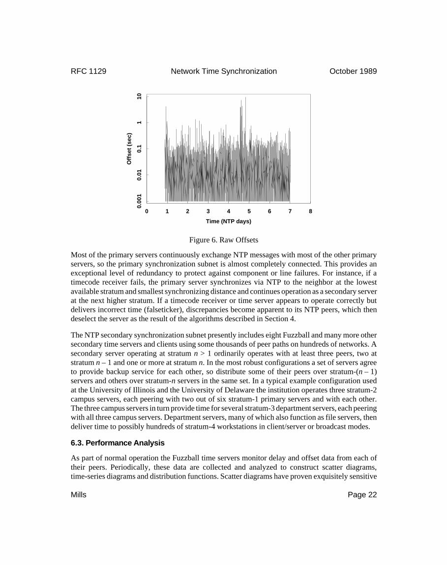
Most of the primary servers continuously exchange NTP messages with most of the other primaryservers, so the primary synchronization subnet is almost completely connected. This provides anexceptional level of redundancy to protect against component or line failures. For instance, if atimecode receiver fails, the primary server synchronizes via NTP to the neighbor at the lowestavailable stratum and smallest synchronizing distance and continues operation as a secondary serverat the next higher stratum. If a timecode receiver or time server appears to operate correctly butdelivers incorrect time (falseticker), discrepancies become apparent to its NTP peers, which thendeselect the server as the result of the algorithms described in Section 4.
The NTP secondary synchronization subnet presently includes eight Fuzzball and many more othersecondary time servers and clients using some thousands of peer paths on hundreds of networks. Asecondary server operating at stratum n > 1 ordinarily operates with at least three peers, two atstratum n – 1 and one or more at stratum n. In the most robust configurations a set of servers agreeto provide backup service for each other, so distribute some of their peers over stratum-(n – 1)servers and others over stratum-n servers in the same set. In a typical example configuration usedat the University of Illinois and the University of Delaware the institution operates three stratum-2campus servers, each peering with two out of six stratum-1 primary servers and with each other.The three campus servers in turn provide time for several stratum-3 department servers, each peeringwith all three campus servers. Department servers, many of which also function as file servers, thendeliver time to possibly hundreds of stratum-4 workstations in client/server or broadcast modes.
6.3. Performance Analysis
As part of normal operation the Fuzzball time servers monitor delay and offset data from each oftheir peers. Periodically, these data are collected and analyzed to construct scatter diagrams,time-series diagrams and distribution functions. Scatter diagrams have proven exquisitely sensitive
Time (NTP days)
Off
set
(sec
)
0 1 2 3 4 5 6 7 8
0.00
10.
010.
11
10
Figure 6. Raw Offsets
RFC 1129 Network Time Synchronization October 1989
Mills Page 22

indicators of system performance and possible malfunctions. A well performing peer path, such asshown in Figure 4, exhibits a distinct wedge-shaped opening to the right and with a sharp apex. Astraffic increases on the peer path the wedge fills and extends to the right, showing increased delaysand delay dispersions. Asymmetrical paths often show distinct asymmetries of delay dispersionsreadily detected by eye.
Time-series diagrams are useful for assessing algorithm performance and systematic errors. Figures6 and 7, constructed from the same data as Figure 4, compare the absolute raw offsets and filtered
Time (NTP days)
Off
set
(sec
)
0 1 2 3 4 5 6 7 8
0.00
10.
010.
11
10
Figure 7. Filtered Offsets
Offset (sec)
Pro
b (
%)
0.001 0.01 0.1 1 10
0.01
0.1
110
100
Figure 8. Error Distribution
RFC 1129 Network Time Synchronization October 1989
Mills Page 23

offsets, respectively, between two primary time servers over an interval of about a week in UTChours. The servers, each synchronized to WWVB to within about a millisecond, are connected bya path including the ARPANET and an unknown number of LANs and gateways. In typical suchcases the reduction in mean offset measurement error is about tenfold. However, the most dramaticreduction with the filter is in maximum error, for which distribution functions with log-log axes aremost useful. Figure 8 shows such a function for the above path and the absolute raw offsets (uppercurve) and filtered offsets (lower curve), from which it is apparent that the maximum error after thefilter is less than about 30 ms for all but about one percent of the samples and less than about 50 msfor all samples.
7. Future Directions
The IRIG-H timecode format established in 1970 and used since then by NBS/NIST radio broadcastservices does not include year information, which must be entered manually after reboot at theprimary time servers. While the year information, once entered, rolls over at the new year, it hassometimes happened that the year was entered incorrectly after reboot, with surprisingly disruptiveeffects on file archiving systems. In addition, the current timecode formats do not include advancenotice of leap-second insertion. Clearly, a revised timecode format including these data is needed.In fact, the recently introduced NBS telephone time service [NBS88] does include both the yearand advance leap-second information.
The current mechanism of time delivery using WWVB, WWV and GOES requires relativelyexpensive timecode receivers subject to occasional disruption due to propagation path or transmitterfailure. Radionavigation systems such as LORAN-C and the Global Positioning System (GPS) arecapable of delivering accurate time and frequency information over major portions of the world;however, these systems do not include an unambiguous timecode modulation and appropriatereceivers are not yet available. An agenda should be pursued to provide a precise timecode as partof normal service.
As experience accumulates, improvements are being made continuously to the filtering and selectionalgorithms described in this paper. For example, a possible way to improve accuracy involves thecombination of selected peer offsets and computing the ensemble offset using techniques suggestedin [BLA74]. Another improvement involves the dynamic activation of selected peer associationswhen other peer associations become unreachable. The intent of this suggestion is to further reducethe polling overheads when a large number of possible peers are available, but only a few are neededfor reliable synchronization.
At present, NTP support is available only for Fuzzball and Unix systems. Support is needed forother systems, including personal workstations of various manufacture. While NTP has beenevolved within the Internet protocol suite, there is obvious application to the ISO protocol suite, inparticular the protocols of the connectionless (CNLS) branch of that suite. Perhaps the mostattractive methodology would be to integrate NTP functions directly into the ES-IS and IS-IS routingfunctions and network management systems.
RFC 1129 Network Time Synchronization October 1989
Mills Page 24

8. References
[BER87] Bertsekas, D., and R. Gallager. Data Networks. Prentice-Hall, Englewood Cliffs, NJ,1987.
[BLA74] Blair, B.E. (Ed.). Time and Frequency Theory and Fundamentals. National Bureau ofStandards Monograph 140, U.S. Department of Commerce, 1974.
[BRA80] Braun, W.B. Short term frequency effects in networks of coupled oscillators. IEEE Trans.Communications COM-28, 8 (August 1980), 1269-1275.
[COL88] Cole, R., and C. Foxcroft. An experiment in clock synchronisation. The Computer Journal31, 6 (1988), 496-502.
[DAR81a] Defense Advanced Research Projects Agency. Internet Control Message Protocol.DARPA Network Working Group Report RFC-792, U.S.C. Information Sciences Institute,September 1981.
[DAR81b] Defense Advanced Research Projects Agency. Internet Protocol. DARPA NetworkWorking Group Report RFC-791, U.S.C. Information Sciences Institute, September 1981.
[GUS84] Gusella, R., and S. Zatti. TEMPO - A network time controller for a distributed BerkeleyUNIX system. IEEE Distributed Processing Technical Committee Newsletter 6, NoSI-2 (June1984), 7-15. Also in: Proc. Summer 1984 USENIX (Salt Lake City, June 1984).
[GUS85a] Gusella, R., and S. Zatti. The Berkeley UNIX 4.3BSD time synchronization protocol:protocol specification. Technical Report UCB/CSD 85/250, University of California, Berkeley,June 1985.
[GUS85b] Gusella, R., and S. Zatti. An election algorithm for a distributed clock synchronizationprogram. Technical Report UCB/CSD 86/275, University of California, Berkeley, December1985.
[HAL84] Halpern, J.Y., B. Simons, R. Strong and D. Dolly. Fault-tolerant clock synchronization.Proc. Third Annual ACM Sympos. on Principles of Distributed Computing (August 1984),89-102.
[KOP87] Kopetz, H., and W. Ochsenreiter. Clock synchronization in distributed real-time systems.IEEE Trans. Computers C-36, 8 (August 1987), 933-939.
[LAM78] Lamport, L., Time, clocks and the ordering of events in a distributed system. Comm. ACM21, 7 (July 1978), 558-565.
[LAM85] Lamport, L., and P.M. Melliar-Smith. Synchronizing clocks in the presence of faults.JACM 32, 1 (January 1985), 52-78.
[LIN80] Lindsay, W.C., and A.V. Kantak. Network synchronization of random signals. IEEETrans. Communications COM-28, 8 (August 1980), 1260-1266.
RFC 1129 Network Time Synchronization October 1989
Mills Page 25

[LUN84] Lundelius, J., and N.A. Lynch. A new fault-tolerant algorithm for clock synchronization.Proc. Third Annual ACM Sympos. on Principles of Distributed Computing (August 1984),75-88.
[MAR85] Marzullo, K., and S. Owicki. Maintaining the time in a distributed system. ACMOperating Systems Review 19, 3 (July 1985), 44-54.
[MIL81] Mills, D.L. Time Synchronization in DCNET Hosts. DARPA Internet Project ReportIEN-173, COMSAT Laboratories, February 1981.
[MIL83a] Mills, D.L. Internet Delay Experiments. DARPA Network Working Group ReportRFC-889, M/A-COM Linkabit, December 1983.
[MIL83b] Mills, D.L. DCN local-network protocols. DARPA Network Working Group ReportRFC-891, M/A-COM Linkabit, December 1983.
[MIL85a] Mills, D.L. Algorithms for synchronizing network clocks. DARPA Network WorkingGroup Report RFC-956, M/A-COM Linkabit, September 1985.
[MIL85b] Mills, D.L. Experiments in network clock synchronization. DARPA Network WorkingGroup Report RFC-957, M/A-COM Linkabit, September 1985.
[MIL85c] Mills, D.L. Network Time Protocol (NTP). DARPA Network Working Group ReportRFC-958, M/A-COM Linkabit, September 1985.
[MIL88] Mills, D.L. The fuzzball. Proc. ACM SIGCOMM 88 Symposium (Palo Alto, CA, August1988), 115-122.
[MIL89a] Mills, D.L. Network Time Protocol (Version 2) specification and implementation.DARPA Network Working Group Report RFC-1119, University of Delaware, September 1989.
[MIL89b] Mills, D.L. Measured performance of the Network Time Protocol in the Internet system.DARPA Network Working Group Report RFC-1128, University of Delaware, October 1989.
[MIT80] Mitra, D. Network synchronization: analysis of a hybrid of master-slave and mutualsynchronization. IEEE Trans. Communications COM-28, 8 (August 1980), 1245-1259.
[NBS79] Time and Frequency Dissemination Services. NBS Special Publication 432, U.S. Depart-ment of Commerce, 1979.
[NBS88] Automated Computer Time Service (ACTS). NBS Research Material 8101, U.S. Depart-ment of Commerce, 1988.
[POS80] Postel, J. User Datagram Protocol. DARPA Network Working Group Report RFC-768,USC Information Sciences Institute, August 1980.
[POS83a] Postel, J. Daytime protocol. DARPA Network Working Group Report RFC-867, USCInformation Sciences Institute, May 1983.
RFC 1129 Network Time Synchronization October 1989
Mills Page 26
[POS83b] Postel, J. Time protocol. DARPA Network Working Group Report RFC-868, USCInformation Sciences Institute, May 1983.
[REF85] Reference Data for Engineers: Radio, Electronics, Computer and Communications(Seventh Edition). Howard W. Sams, Indianapolis, IN, 1985.
[RIC88] Rickert, N.W. Non Byzantine clock synchronization - a programming experiment. ACMOperating Systems Review 22, 1 (January 1988), 73-78.
[SCH86] Schneider, F.B. A paradigm for reliable clock synchronization. Department of ComputerScience Technical Report TR 86-735, Cornell University, February 1986.
[SRI87] Srikanth, T.K., and S. Toueg. Optimal clock synchronization. JACM 34, 3 (July 1987),626-645.
[SU81] Su, Z. A specification of the Internet protocol (IP) timestamp option. DARPA NetworkWorking Group Report RFC-781. SRI International, May 1981.
[TRI86] Tripathi, S.K., and S.H. Chang. ETempo: a clock synchronization algorithm for hierarchi-cal LANs - implementation and measurements. Systems Research Center Technical ReportTR-86-48, University of Maryland, 1986.
Security considerationsSee Section 3.3.
Author’s addressDavid L. MillsElectrical Engineering DepartmentUniversity of DelawareNewark, DE 19716Phone (302) 451-8247EMail [email protected]
RFC 1129 Network Time Synchronization October 1989
Mills Page 27