Internet Telephony Gateway VIP-050 / VIP-450 User s Manual
83
Internet Telephony Gateway VIP-050 / VIP-450 User’s Manual Rev 2.0
Transcript of Internet Telephony Gateway VIP-050 / VIP-450 User s Manual

Internet Telephony Gateway
VIP-050 / VIP-450
User’s Manual
Rev 2.0

SIP Voice Gateway User’s Manual
Preface ii
FCC Notice This equipment has been tested and found to comply with the limits for a Class A digital de-vice, pursuant to Part 15 of FCC Rules. These limits are designed to provide reasonable pro-tection against harmful interference when the equipment is operated in a commercial environ-ment. This equipment generates, uses, and can radiate radio frequency energy and, if not in-stalled in accordance with the instruction manual, may cause harmful interference to radio communication. Operation of this equipment in a residential area is likely to cause harmful in-terference in which case the user will be required to correct the interference at the user’s own expense. Disclaimer PLANET Technology does not warrant that the hardware will work properly in all environments and applications, and makes no warranty and representation, either implied or expressed, with respect to the quality, performance, merchantability, or fitness for a particular purpose. PLANET has made every effort to ensure that this User’s Manual is accurate; PLANET dis-claims liability for any inaccuracies or omissions that may have occurred. Information in this User’s Manual is subject to change without notice and does not represent a commitment on the part of PLANET. PLANET assumes no responsibility for any inaccuracies that may be contained in this User’s Manual. PLANET makes no commitment to update or keep current the information in this User’s Manual, and reserves the right to make improve-ments to this User’s Manual and/or to the products described in this User’s Manual, at any time without notice. If you find information in this manual that is incorrect, misleading, or incomplete, we would appreciate your comments and suggestions. CE Declaration of conformity This equipment complies with the requirements relating to electromagnetic compatibility, EN 55022 class A for ITE and EN 50082-1. This meets the essential protection requirements of the European Council Directive 89/336/EEC on the approximation of the laws of the Member States relating to electromagnetic compatibility. Trademarks All brand, company and product names are trademarks or registered trademarks of their re-spective companies. Revision PLAENT VIP-050 / VIP-450 User’s Manual Revision: 2.0 Nov. 2004 Part No. EM-VIPSV2

SIP Voice Gateway User’s Manual
Preface iii
How to Use This Manual
This manual was designed for the technical and non-technical users of PLANET Internet telephony gateway VIP-050 / VIP-450. It contains information about the functions of VIP and instructions for its installation, basic configuration and operation in related chapters, and introduces more advanced command line interface, firmware upgrade and appendix information. Read this section carefully for important information about the manual’s organization.
Chapter 1: Overview This chapter provides conceptual overview and description of VIP, explanation of how VIP interacts with each for enabling VoIP services, and an overview of the required tasks
Chapter 2: Installing VIP This chapter describes required steps to properly and safely install and configure VIP on your net-work
Chapter 3: VIP Concepts This chapter gives information about VIP technology and describes basic concepts using VIP for providing telephony services over IP network
Chapter 4: Configuring VIP from Web Browser This chapter explains procedures for configuring VIP from a web browser
Chapter 5: Making a Call with VIP This chapter explains how to make Internet calls from telephony devices connected to VIP directly or indirectly.
Chapter 6: Command Line Interface This chapter describes how to access the command line interface. It also contains information about the commands used to configure VIP. Chapter 7: Upgrading VIP This chapter explains how to download new revision software and upgrade VIP.
Appendix A: Technical Specifications This appendix lists VIP specifications and the assignment of pins of all the interface ports.
Appendix B: CLI Commands This appendix provides a short description of each CLI command with a reference to the pages that contain detailed information on the command.
Appendix C: Factory Default Settings This appendix lists factory settings of VIP.
SIP Voice Gateway User’s Manual
Preface iv
Important Safety Instructions Before plugging VIP into an electrical outlet, carefully read all the installation instructions in Chapter 2.
For your own safety and the safety of your equipment, always take the following precautions:
• Follow instructions and warnings in the documentation.
• Never push any object through the fan vent or other openings in the equipment. Such action may produce a short circuit, causing fire, electric shock, or equipment damage.
• Keep VIP away from all chemicals and sources of liquids.
Warning • Connection of the RJ45 connector from a VIP to TNV circuits can cause permanent damage to
VIP.
• Incorrectly connecting telephony devices to the RJ11 port on the Telephony Interface Module can cause permanent damage to the module.
Documentation Abbreviations Throughout this guide, the user will come across a number of abbreviations that are common throughout the industry. The user should be familiar with the following abbreviations:
ATPM Address Translation and Parsing Manager
CLI Command Line Interface
DSP Digital Signal Processor
DTMF Dual Tone Multi-Frequency
E&M Ear & Mouth
FXO Foreign Exchange Office
FXS Foreign Exchange Subscriber
SIP ITU specification for multimedia transmission over IP networks
ICMP Internet Control Message Protocol
IMTC International Multimedia Telecommunications Consortium
IP Internet Protocol
ITG Internet Telephony Gateway
KTS Key Telephone System
LAN Local Area Network
NVS Non-Volatile Storage

SIP Voice Gateway User’s Manual
Preface v
LED Light Emitting Diode
PBX Private Branch Exchange
PSTN Public Switched Telephone Network
RTP Real-Time Transport
SIP Session Initialization Protocol
TCID Telephony Channel Identifier
TFTP Trivial File Transfer Protocol TIM Telephony Interface Modules TNV Telephone Network Voltage UDP User Datagram Protocol UTP Unshielded Twisted Pair VAD Voice Activity Detection
WAN Wide Area Network
Notation Conventions
Throughout this guide, different type styles and characters are used. These serve a variety of pur-poses as described below:
Convention Description boldface Commands and keywords are in boldface.
italic Arguments for which you supply values are in italics. courier Messages that VIP CLI displays are in plain courier font.
[ ] Elements in square brackets are optional. x | y | z Alternative but required elements are grouped in braces ( ) and sepa-
rated by vertical bars ( | ). [ x | y | z ] Optional alternative keywords are grouped in brackets ([ ]) and separated
by vertical bars ( | ). string A nonquoted set of characters. Do not use quotation marks around the
string or the string will include the quotation marks.

SIP Voice Gateway User’s Manual
Preface vi
Table of Contents
Chapter 1 Overview 1
1.1 Features 1 1.2 Networking Protocols 1 1.3 Package Contents 2 1.4 Front Panel 2 1.5 Rear Panel 3
Chapter 2 Installing VIP 5
2.1 Network Requirements 5 2.2 Installing VIP 5 2.3 Connecting to the telephony devices 5 2.4 Connecting to the Network 5 2.5 Providing Power to VIP 6 2.6 Assigning IP address to VIP 6
Chapter 3 VIP Concepts 7
3.1 How VIP Operates 7 3.2 ATPM 7 3.3 Destination 7 3.4 Hunt Group 8 3.5 Dial Plan 8 3.6 DTMF Relay 9 3.7 Voice Codecs 9
Chapter 4 Configuring VIP from a Web Browser 11
4.1 Http setting mode 11 4.1.1 Dial Plan/ Dial Settings 13 4.1.2 Clear DialPlan 19 4.1.3 Restore DialPlan 20 4.1.4 Save to NVRAM 20
4.2 View System Configurations 21 4.2.1 Firmware Version Information 21 4.2.2 SIP Parameters 21 4.2.3 Voice Coder Type 22 4.2.4 Voice Coder Information 22
SIP Voice Gateway User’s Manual
Preface vii
4.2.5 Channel Parameters 23 4.2.6 Network Connection 24
4.3 Configure System Settings 28 4.3.1 IP Settings 30 4.3.2 SIP Parameters 30
Chapter 5 Troubleshooting Tips 34
Chapter 6 Command Line Interface 35
6.1 Connection through Serial Port 35 6.2 Connection through Telnet 35 6.3 Command Help 36 6.4 Designating IP Address 36 6.5 Designating Port Number 36 6.6 Command Reference 37 6.7 Utility Commands 38 6.8 Network Commands 39 6.9 Configuration Management Commands 44 6.10 Voice Coding Profile Configuration Commands 48
6.10.1 Common Coding Profile Configuration Commands 48 6.10.2 Voice Coding Profile Configuration Commands 49
6.11 Dial Plan Management Commands 52 6.12 Tel Commands 57
Chapter 7 Upgrading and resetting VIP 59
7.1 Firmware upgrade 59 7.2 CLI Commands in Download Mode 64 7.3 Restore default configuration 65
Appendix A Technical Specifications 69
A.1 VIP Technical Specifications 69 A.2 Console Port 70 A.3 LAN Port 70 A.4 FXO Port Pin Assignments 71 A.5 FXS Port Pin Assignments 71
Appendix B CLI Commands 73
B.1 Normal Mode Commands 73

SIP Voice Gateway User’s Manual
Preface viii
B.2 Download Mode Commands 74
Appendix C Factory Default Settings 75

VIP User’s Manual
Overview 1
Chapter 1 Overview
This chapter illustrates an overview of PLANET Internet Telephony Gateway Family –
VIP-050 / VIP-450 and a detailed product description of features and capabilities.
1.1 Features Via growth of Internet technology, Internet telephony service plays and turns into a cost-effective and highly reliable substitution system of the old-time traditional PBX system. PLANET VoIP (Voice over IP) system – VIP-050 / VIP-450 offer toll quality voice and real-time fax data over IP networks. With optimized SIP architecture, PLANET VIP series are ideal solution for various VoIP applications such as Headquarter and Branch Office communication, and IDD cost-effective solution. With its intuitive user-friendly interface, PLANET VIP series may be installed easily conveniently, and dramatically down cost the huge amount of IDD fee.
With embedded, efficient Real-Time Operating System, VIP series provides efficiency and feature enhancement capabilities; being programmed with updated firmware users may have the most flexibility and functionality to meet different kind of application requirement. It comes equipped with remote management capabilities, configurable signaling to work with PBX, KTS, and/or telephone. Building on state-of-the-art advanced VoIP related technology. PLANET VVIP series offers various features: echo cancellation, Voice Activity Detection (VAD) , Comfort Noise Generation (CNG) , lost packet recovery algorithms and optimized voice and FAX coders to bring users superior voice qual-ity, and best compatibility with major Internet telephony service providers.
1.2 Networking Protocols VIP supports several industry-standard networking protocols required for voice communication. The following table describes these protocols.
Networking Protocol Description Internet Protocol (IP) IP is a messaging protocol that addresses and sends packets across the
network. To enable IP protocol, VIP must have a static IP address, subnet, and gateway assigned to it.
Voice over IP Protocol (VoIP)
VoIP enables VIP to transfer voice communications over an IP network. VIP employs ITU-T SIP protocol for setting up call with one another.
Trivial File Transfer Protocol (TFTP)
TFTP allows you to transfer files over the network. VIP implements a TFTP client allowing you to download new revision firmware from a TFTP server. The TFTP client requires a TFTP server in your network.
Real-Time Transport (RTP)
RTP is a standard for transporting real-time data over IP network. VIP uses RTP protocol to send digitized and compressed voice packets.

SIP Voice Gateway User’s Manual
Overview 2
1.3 Package Contents The contents of your product should contain the following items:
VIP-050 l 2-slot Internet Telephony Gateway l Power cord l 9-pin straight through RS-232 cable l Quick Installation Guide l User’s Manual CD l Rack mount Accessories
VIP-450 l 4-port Internet Telephony Gateway l Power cord l 9-pin straight through RS-232 cable l Quick Installation Guide l User’s Manual CD
1.4 Front Panel The front panel of VIP contains a RJ-45 Ethernet port, one DB9 RS-232 interface port, a push but-ton and 16 LED indicators. The following figure illustrates the front panel of VIP.
Figure 1-1 VIP-050 Front Panel
Figure 1-2 VIP-450 Front Panel
LED Indicators The LED indicators on the front panel display the current status of VIP as described in the following table:
Indicator Color Activity Indication

SIP Voice Gateway User’s Manual
Overview 3
PWR Green On Power is supplied to the gateway.
SYSTEM Green Blinking The system is running. (Heartbeat LED)
LAN ACT 100M LNK COL
Green Green Green Green
On On Off On On
Data is presented on LAN. The gateway is connected to LAN at 100Mb/s. The gateway is connected to LAN at 10Mb/s. The gateway is connected to LAN. Data collision is occurring on the network connection.
Slot A/B Channels 1-4
Green Off On Blinking
The line is idle. The line is being used. The line is ringing.
Ports VIP is equipped with an Ethernet interface with 10/100 Mbps auto-negotiation capability. The Ethernet interface port is located on the front panel. In addition to the Ethernet interface port, there is a 9-pin RS-232 interface port on the front panel. Their functions are described below:
Port Label Function RJ45 LAN Connecting VIP to a 10/100 Mbps Ethernet network
9-pin RS-232 User Console Connecting VIP to a VT-100 terminal or terminal emulator for con-figuring VIP
Reset Button There is a push button located behind a small hole next to the SYSTEM LED. This button allows you to reset VIP or force VIP to enter firmware upgrade mode.
Reset Push a small, stiff object into the hole until the SYSTEM LED stops blinking, then release the but-ton.
Force firmware download mode: Powering on the gateway while pressing down the button for 5 seconds forces VIP to enter download mode
1.5 Rear Panel The rear panel of VIP-050 has two slots allowing the installation of up to two Telephony-Interface- Module (TIM) . Each module is equipped with 4 telephony interface ports. Depending on the type of the telephony interface module, the telephony interface ports may be connected to telephony de-vices, such as PBX, KTS, and telephone sets of central office. VIP-450 equips with two FXO and two FXS ports. In addition to the TIM slots (ports), there is an AC power receptacle and a power switch (power adapter: VIP-450) on the rear panel.

SIP Voice Gateway User’s Manual
Overview 4
Slot A Slot B
VIP-050 Rear Panel
VIP-450 Rear Panel
Note: For VIP-050, three modules available, VIP-FXS, VIP-FXO and VIP-E&M. Modules are not included, please consult your local dealer for the information of the modules.
4 3 1 2 2 1
50~60H
90~240VA SLOT A
ELITE-FXO ELITE-FXS SLOT B

VIP User’s Guide
Installing VIP 5
Chapter 2 Installing VIP
This chapter gives information on how to install VIP.
2.1 Network Requirements For VIP successfully operate in your network, your network must meet the following requirements:
1. A working 10/100 Base-T Ethernet. VIP connects to Internet via an Ethernet LAN.
2. IP network that supports gateway, and subnet mask. You’ll need one static IP address to as-sign VIP.
2.2 Installing VIP VIP can be used in a desktop configuration. Ensure that VIP is placed in a clean, well-ventilated, and vibration-free environment.
When VIP is placed on a desktop, be certain that the unit is placed on a sturdy, flat surface, near a grounded power outlet. At least three inches of clearance must be provided on both sides of VIP for well ventilation.
2.3 Connecting to the telephony devices VIP-050 supports three types of TIM. One is FXO, FXS and the other is E&M. Each module has four ports for connecting to telephony devices. VIP-450 equips two FXO and two FXS interfaces to have the great flexibility of PBX connection (FXO), and telephone or FAX machine connection (FXS).
VIP-FXO module is designed for connecting to PBXs (extension line) or central office switches (CO line).
VIP-FXS module is designed for connecting to analog telephone sets or G3 fax machines. Connecting the telephony devices to the appropriate RJ11 ports on the TIM.
Warning: connection of incorrect telephony devices to the ports on the TIM can cause permanent damage to the TIM and/or VIP.
2.4 Connecting to the Network The RJ45 network port on the front panel supports 10/100 Mbps half-duplex connection to Ethernet Network. You can use either category 3 or 5 straight-through UTP cable for 10 Mbps connections, but use Category 5 for 100 Mbps connections. To connect to Ethernet, insert one end of the Ethernet cable to the RJ45 port on the front panel of VIP and other end of the cable to an Ethernet switching hub or repeater hub.

VIP User’s Manual
Installing VIP 6
2.5 Providing Power to VIP To provide AC power to VIP complete the following steps:
1. Turn the power switch on the rear panel of VIP to the off position.
2. Connect one end of the power cord that came with VIP to the power receptacle on the rear panel.
3. Connect the other end of the power cord to an AC power outlet.
4. Turn the power switch on. VIP will perform power on self-test. After completing the self-test, the SYSTEM LED blinks continuously and the TIM indicators on the front panel will turn on.
2.6 Assigning IP address to VIP The IP address is the unique logical address identifying each IP node, such as VIP, on an IP net-work. An IP address is a 32-bit number expressed as four decimal numbers from 0 to 255 sepa-rated by periods. VIP needs a static IP address and be aware of the subnet mask and default gateway (typically a router) of your network to be able to send to and receive data from the IP net-work. Consult your network manager to obtain a unique and static IP address for VIP, the IP subnet mask and default gateway of your network, and fill out the work sheet in Appendix D before config-uring the gateway. Procedures for assigning IP address, default gateway and subnet mask is avail-able in Chapter 4.
VIP User’s Manual
VIP Concepts 7
Chapter 3 VIP Concepts
VIP enables the transmission of voice and fax traffic over any IP network by digitizing voice and fax signals, encapsulating the information within IP packets, and then sending the packets across the IP network
3.1 How VIP Operates 1. The TIM inside VIP digitizes analog voice signals at 8 Kbps.
2. VIP system software handles the:
Capture of telephone number presented as DTMF tones.
Mapping the telephone number to the IP address of remote VIP.
Setting up calls with remote VIPs utilizing SIP call control protocol.
Digitizing, compressing and encapsulating the voice into IP packets and transmission of the IP packets onto the Ethernet LAN.
3. A router attached to the LAN forwards the IP packets across the WAN, where they will be re-ceived by another VIP at the remote.
4. The process is reversed at the remote VIP.
3.2 ATPM To allow you to easily dial a telephone or fax on the network, VIP maps a series of dialed digits to the IP address of the remote VIP whose phone or fax you are calling. This mapping information is contained in a database inside each VIP called the dial plan.
Based on the dial plan the Address Translation and Parsing Manager (ATPM) inside VIP translates telephony numbers to IP addresses of remote VIPs. The ATPM collects telephone number dialed by users, decides whether the dial string is part of the dial plan and, if it is, maps it a remote VIP. When the call is set up to the destination, a substring of the original dial string will be sent along to the remote VIP.
3.3 Destination The destination is where a call is terminated. Typically, for inbound calls from IP network, VIP ter-minals the call at one of the telephony ports. The destination for the call is the telephony port where the call terminated. For calls initiated from telephony ports, VIP forward the call to a remote VIP via IP network, and the remote VIP terminal the call. The destination of the call is the remote VIP.

VIP User’s Manual
VIP Concepts 8
3.4 Hunt Group Instead of directly mapping a phone number to a destination, the ATPM first maps the phone num-ber to a group of destinations known as a Hunt Group. A hunt group is a group of destinations that are equivalent. For example, the customer support group of a company might have 20 peo-ple who can handle support calls. Access to customer support is through a single phone number but the next available support person is actually connected upon each incoming call. These 20 phones would be configured as a hunt group. A hunt group consists of a phone number and a list of destinations (members of the group). When an incoming phone number matches the phone number of the hunt group, VIP attempts to terminate the call at each of the destinations in the hunt group, one at a time until a call is successfully completed.
Every destination that can be reached by dialing a phone number is a member of at least one hunt group. When an address is presented to ATPM for lookup, the output is a hunt group ID number. As a second step, the hunt group ID is presented to ATPM to get the list of members. To effectively bypass the hunt group feature, simply make a unique hunt group for each destination and one member in each hunt group.
3.5 Dial Plan The dial plan is a database inside VIP for the ATPM to map telephony numbers users dialed to the IP address of remote VIPs. The dial plan consists of the destination table, hunt group table and the address table. Users need to setup these tables, so that VIP knows how to setup calls with remote VIPs.
Address Table The address table maps a phone number to a hunt group. The table contains entries that specify the following information:
• Telephone number
• The hunt group the phone number maps to.
• The minimum number of digits to collect before the ATPM starting address lookup.
• The maximum number of digits the ATPM collects before it considers the dial string is complete.
• Number of digits forward to the destination.
Address table sample: Address Entry Hunt Grp_Id Min. Digits Max. Digits Prefix strip Prefix Address
200 1 3 3 0 None 201 3 3 3 0 None 899 11 3 3 0 None 8 11 3 3 0 None 0 5 1 1 0 None
03 5 10 10 2 “0”

SIP Voice Gateway User’s Manual
VIP Concepts 9
Hunt Group Table The hunt group table maps a hunt group to a list of destinations.
Hunt group sample
Group id Type #Members Member ids ---------------------------------------------------------------------------- 1 2 1 1 3 2 1 2 5 2 1 4 11 2 1 11
Destination Table The destination table maps a destination to a telephony port or the IP address of a remote VIP.
Destination table sample
Dest id Mode Destination ------------------------------------------------------- 1 Local PORT = 0 3 Local PORT = 2 5 Local PORT = 4 11 SIP Dest = 192.168.0.55/ 5060 12 DNS Dest = planetvip.dyndns.org /5060
3.6 DTMF Relay Voice from PSTN is compressed by VIP before sending across the IP network and then decom-pressed by the destination VIP. The voice coders supported by VIP are designed for ideally com-pressing and decompressing human voice. If the compression / decompression process is per-formed on DTMF tone which needs to be conveyed across IP network, distortion might be too sig-nificant to be not cognizable in the receiving end. To overcome the shortcoming that the voice cod-ers cannot perfectly encode DTMF tone, VIP encodes DTMF tone into special packets. The pack-ets are then sent to the destination VIP via a separate IP connection. The destination VIP decodes the packets, generates the DTMF tone, and then sends the tone to the PSTN. The way VIP han-dles DTMF tone is so called DTMF relay.
VIP handles DTMF relay per SIP specifications. Certain third party VoIP devices may handle DTMF relay per IMTC standard. For VIP to interoperate with those VoIP devices, users need to specify which remote VoIP devices uses IMTC conforming DTMF relay technique. Refer to CLI command for detailed information on how to select DTMF relay mode.
3.7 Voice Codecs Voice codecs supported by VIP include G.711, G.723.1 5.3kbps, G.723.1 6.3kbps and G.729 AB. When setting up a call, two VIP automatically negotiate with each other until an agreed upon codec is determined.


VIP User’s Manual
Configuring VIP from a Web Browser 11
Chapter 4 Configuring VIP from a Web Browser This chapter explains procedures for configuring VIP from the web browser.
4.1 Http setting mode This section describes the processes for setting up Internet Telephony Gateway once it has been in-stalled. Microsoft Explorer version 4 or higher, or Navigator version 4.5 or higher can be used in this section to view and change parameters.
PC Setup In order to configure VIP, PC needs to have TCP/IP protocol and a compatible IP Address. 1. Connect VIP to network with a RJ-45 UTP cable. Power it on. 2. Find a PC, for example, Windows 2000. Under Windows 2000, select the Network Neighborhood
icon on the desktop, then select Properties. We will see a screen like below:
3. If a line like the one highlighted ("TCP/IP -> Network Card”) is not listed , select Add-Protocol-Microsoft-TCP/IP-OK to add it.
4. Select Properties for the “TCP / IP -> Network card” entry. You will see a screen like the following:

VIP User’s Manual
Configuring VIP from a Web Browser 12
5. On the IP Address table, enter values as follows: • Specify an IP address set ON. • IP Address: 192.168.0.2 • Subnet Mask: 255.255.255.0 Restart your PC and Start your WEB browser.
6. In the Address box, enter the following: http://192.168.0.1 (default IP address of the Voice Gateway)
7. Press enter to confirm and you should find the screen below.
8. The User Name is administrator (all lower case) . Password is 123. Both administrator and 123 are default strings from factory). For security reasons, please change and memorize the new pass-word after this first setup.
9. Click “OK”. The main screen will appear as be low.

SIP Voice Gateway User’s Manual
Configuring VIP from a Web Browser 13
4.1.1 Dial Plan/ Dial Settings Main Menu Function Briefings 1.Dial Plan Settings, which helps you configure the dial plan. You should complete the dial plan work
sheets before working on this menu. 2.View System Configurations, which includes the specific information related to version, network,
SIP, coder, and the channel of the gateway you are using. 3.Configure System Settings, which allows you to modify the system parameters as you wish. Select Main Menu\Dial Plan Settings, we can find the following Dial Plan Menu.
Dial Settings The Setup screen of the Dial Plan including:
• Telephone Settings, which allows one to Add, Delete, Find, or List telephone num-bers.
• Hunt Group Settings, which allows one to Add, Delete, Find, or List hunt group set-tings
• Destination Settings, which allows one to Add, Delete, Find, or List destination set-tings
Common Dial Parameters
Defines the desired total dial time, first digit wait time, inter-digit wait time, and the termination digit
Clear Dial Plan Clears all telephone numbers, hunt groups, and destinations settings, for both old and new ones
Restore Dial Plan
Retrieves all dial plan settings from the flash while temporary settings will be cleared
Store to NVRAM
Stores all settings that you have specified perma-nently

VIP User’s Manual
Configuring VIP from a Web Browser 14
4.1.1.1 Phone number Please select Main Menu\Dial Plan\Phone/Hunt Group/Destination Settings, we can find Phone/Hunt Group/Dest. Setting Menu. We are doing VIP telephone address table manage-ment. We can add (delete, find or list) desired telephone number mapping to hunt group at this menu.
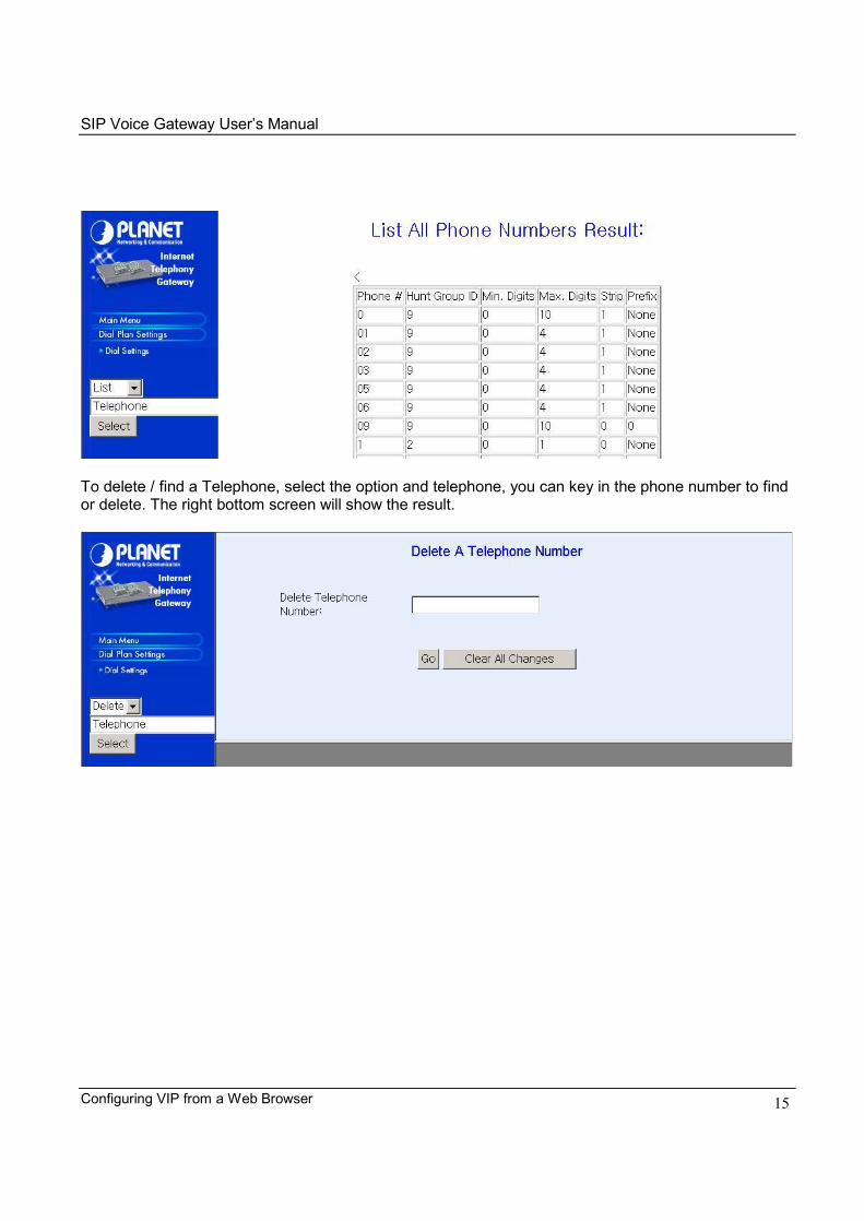
To list the phone numbers, click on “List” and select “Telephone”, the screen will displayed as below:
Telephone Number
Telephone number to match. This is only part of the total dialed string.
Hunt Group ID
For each hunt group ID, you need to assign it a unique identifier between 0 and 99.
Min. Digits Minimum number of digits to be collected be-fore the ATPM starting matching the dial string with entries in the address table.
Max. Dig-its
Maximum number of digits to be collected be-fore the ATPM starting matching the dialed string with entries in the address table.
Strip Length
The number of digits to be stripped at the be-ginning of the collected dial string before for-warding the string to the destination.
Append Prefix
(Optional) Digit to be added before the begin-ning of the collected dial string before forward-ing it to the destination.
SIP Voice Gateway User’s Manual
Configuring VIP from a Web Browser 15
To delete / find a Telephone, select the option and telephone, you can key in the phone number to find or delete. The right bottom screen will show the result.

VIP User’s Manual
Configuring VIP from a Web Browser 16
4.1.1.2 Hunt Group Please select Main Menu\Dial Plan\Phone/Hunt Group/Destination Settings, we can find Phone/Hunt Group/Dest. Setting Menu. We are doing VIP hunt group table management.
We can add (delete, find or list) desired hunt group ID mapping to destination ID at this menu. If you want to make the port calls to the secondary receiver, you can click one “More Destinations” you can then add the second, third receiver if the desired port/phone is busy. We can add (delete, find or list) desired hunt group ID mapping to destination ID at this menu.

SIP Voice Gateway User’s Manual
Configuring VIP from a Web Browser 17
4.1.1.3 Destination IP/ Destination Channel
Please select Main Menu\Dial Plan\Phone/Hunt Group/Destination Settings, we can find Phone/Hunt Group/Dest. Setting Menu. We are doing VIP destination table management. One is Remote Destination IP, one is Remote Host Name and the other is Local Destination Channel.

VIP User’s Manual
Configuring VIP from a Web Browser 18
We can add (delete, find or list) desired destination ID mapping to Remote Destination IP, Domain Name or Local Destination Channel at this menu. Please back to Dial Plan Menu. 4.1.1.4 Common Parameter
Please select Main Menu\Dial Plan\Common Parameter Settings
SIP Voice Gateway User’s Manual
Configuring VIP from a Web Browser 19
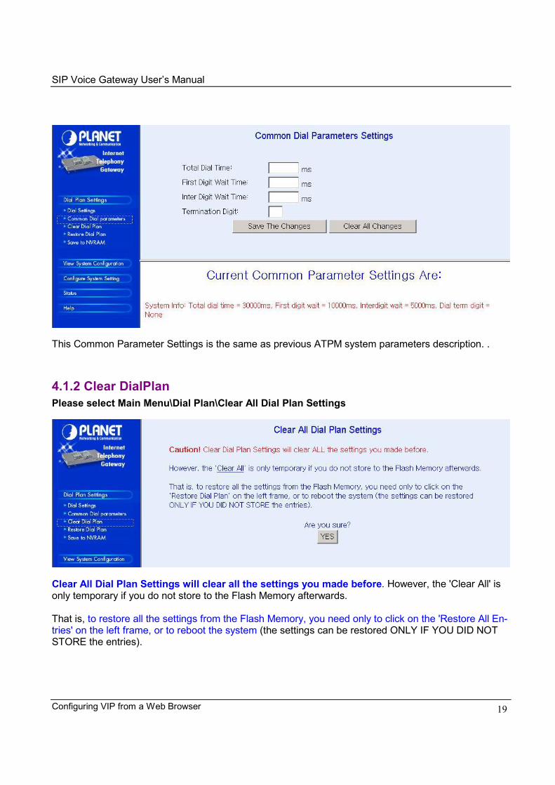
This Common Parameter Settings is the same as previous ATPM system parameters description. .
4.1.2 Clear DialPlan Please select Main Menu\Dial Plan\Clear All Dial Plan Settings
Clear All Dial Plan Settings will clear all the settings you made before. However, the 'Clear All' is only temporary if you do not store to the Flash Memory afterwards. That is, to restore all the settings from the Flash Memory, you need only to click on the 'Restore All En-tries' on the left frame, or to reboot the system (the settings can be restored ONLY IF YOU DID NOT STORE the entries).

VIP User’s Manual
Configuring VIP from a Web Browser 20
4.1.3 Restore DialPlan Please select Main Menu\Dial Plan\Restore All Dial Plan Settings Retrieve all dial plan settings from the flash memory. All temporary settings will be cleared.
4.1.4 Save to NVRAM Please select Main Menu\Dial Plan\ Save to NVRAM Ready to store Dial Plan settings to Flash Memory
Please Back To Main Menu

SIP Voice Gateway User’s Manual
Configuring VIP from a Web Browser 21
4.2 View System Configurations
Please select Main Menu\View System Config.
View System Config. Function Briefings. Six options available 1.Firmware Version Information, which shows the versions of each firmware component 2.Network Settings, which shows the IP-related settings, and the status of associated management
tools 3.SIP Parameter Settings, which shows the SIP-related parameters associated with the gateway 4.Coding Profile Information, which shows the configurations related to a specific coding profile 5.Channel Settings, which shows the configurations associated with a specific channel 6.Network Connection, which shows type of connection enabled in VIP
4.2.1 Firmware Version Information Please select Main Menu\View System Config.\Firmware Version Info. This will show current VIP firmware version information. Firmware Information:
Internet Telephony Gateway (PLA) Version: s1.0 Boot Loader Version: 4.13 RTOS Version: 2.5.0/BE SIP Stack Version: 2.1.1.4 DSP image Version: 8.1.2.1. TSG Version: R8.0 Gateway (Build 4)
4.2.2 SIP Parameters Please select Main Menu\View System Config.\SIP Parameter Settings The SIP Parameters Settings:

VIP User’s Manual
Configuring VIP from a Web Browser 22
SIP Addr Configuration: UDP ctl addr = 192.168.0.99/5060 RTP data addr = 192.168.0.99/2070 Domain name server = 168.95.192.1 Info switch is off nat_call is on auto_reg is off outboundproxy : None
4.2.3 Voice Coder Type Please select Main Menu\View System Config.\Coder Type The Voice Coder For Each Line Module: Voice coder is G.723 for Line Module 1.
4.2.4 Voice Coder Information Please select Main Menu\View System Config.\Coder Information
SIP Voice Gateway User’s Manual
Configuring VIP from a Web Browser 23
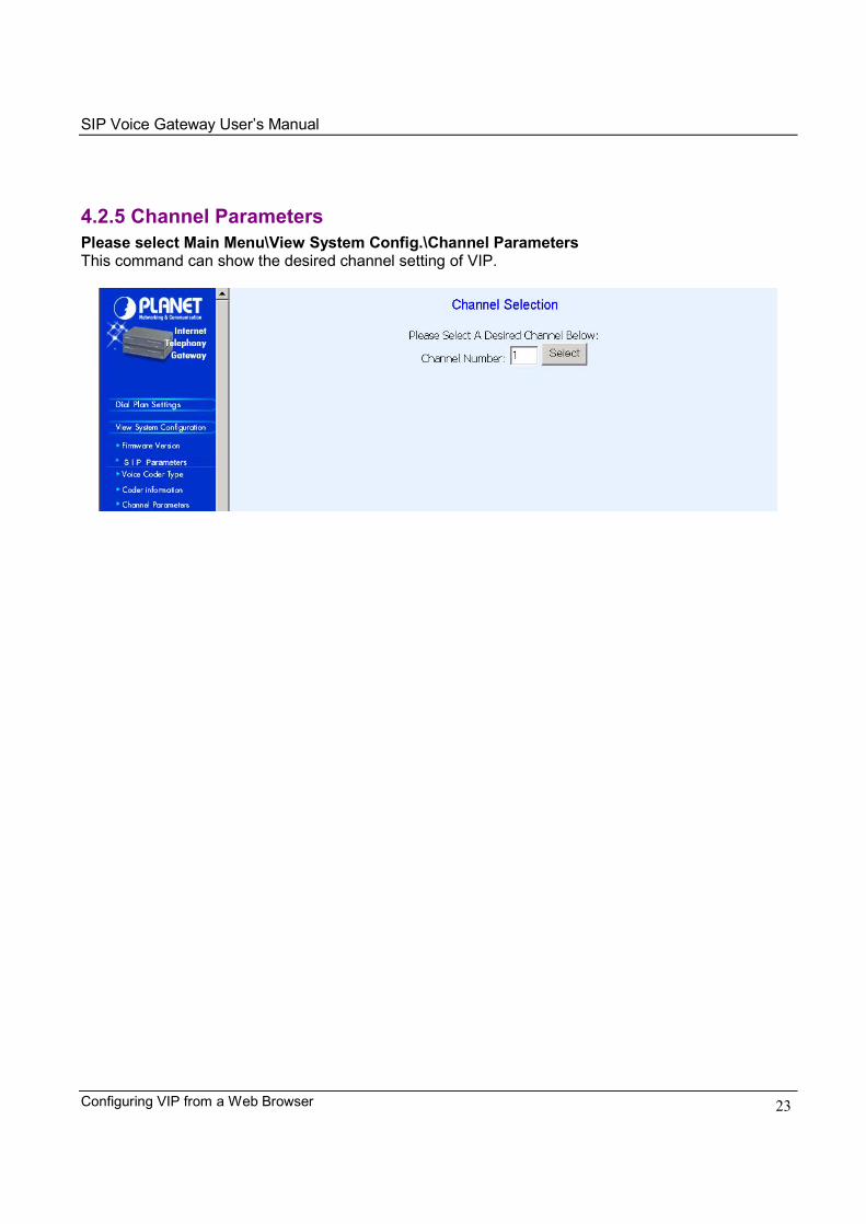
4.2.5 Channel Parameters Please select Main Menu\View System Config.\Channel Parameters This command can show the desired channel setting of VIP.

VIP User’s Manual
Configuring VIP from a Web Browser 24
4.2.6 Network Connection Please select Main Menu\View System Config\Network Connection This command can display the type of connection currently enabled in VIP.
4.2.6.1 DHCP Settings Display current DHCP status in VIP
Command Line Interface reference: net set dhcp net set dhcp command configures VIP to be DHCP client in order to obtain TCP/IP related pa-rameters from ISP while VIP is deployed in DHCP environment.
Syntax Description
on Turn on DHCP client
off Turn off DHCP client
If DHCP client is enabled/disabled, VIP has to be rebooted to make the DHCP service started/stopped.

SIP Voice Gateway User’s Manual
Configuring VIP from a Web Browser 25
4.2.6.2 PPPoE Settings Display current PPPoE status in VIP
Command Line Interface reference: net set pppoe The net set pppoe command configures PPPoE related parameters while VIP is deployed in PPPoE environment.
Syntax Description
on Turn on PPPoE client
off Turn off PPPoE client
username PPPoE connection username provided by ISP

VIP User’s Manual
Configuring VIP from a Web Browser 26
password PPPoE connection password provided by ISP
fix_ip Fixed IP address provided by ISP
If PPPoE client is enabled/disabled, VIP has to be rebooted to make the PPPoE service started/stopped.

SIP Voice Gateway User’s Manual
Configuring VIP from a Web Browser 27
4.2.6.3 DDNS Settings Display current DDNS status in VIP
Command Line Interface reference:
net set dyndns

VIP User’s Manual
Configuring VIP from a Web Browser 28
DDNS service can help users to find each other in dynamic/static IP environment, and enable two VIPs call each other with registered host names. To be fully functional, DNS server MUST be added into SIP configuration while DDNS service is enabled.
DDNS clients supported in VIP are www.dyndns.org and www.dtdns.com currently.
If VIP DDNS client is enabled, users MUST register a DDNS name from the sites listed above be-fore proceeding any further.
Syntax Description
on Turn on DDNS client
off Turn off DDNS client
If DDNS client is enabled, VIP has to be rebooted to make the DDNS service effective.
sub commands: set dyndns add [serv_name] [host_name] [user_name] [password] Adding applied DDNS name into VIP database.
Note: if multiple DDNS names are inserted, only the first one will be updated.
Syntax Description
serv_name DDNS service server (MUST be “dyndns” or “dtdns” for now)
host_name DDNS name registered from DDNS service provider
user_name Username used to update DDNS account
password Password used to update DDNS account
set dyndns delete [host_name]|all Delete specified or all DDNS name(s) configured in VIP.
DDNS related parameters must be saved via commands: “config activate, config store” in order to be effective.
4.3 Configure System Settings
Please select Main Menu\Configure System Settings
SIP Voice Gateway User’s Manual
Configuring VIP from a Web Browser 29
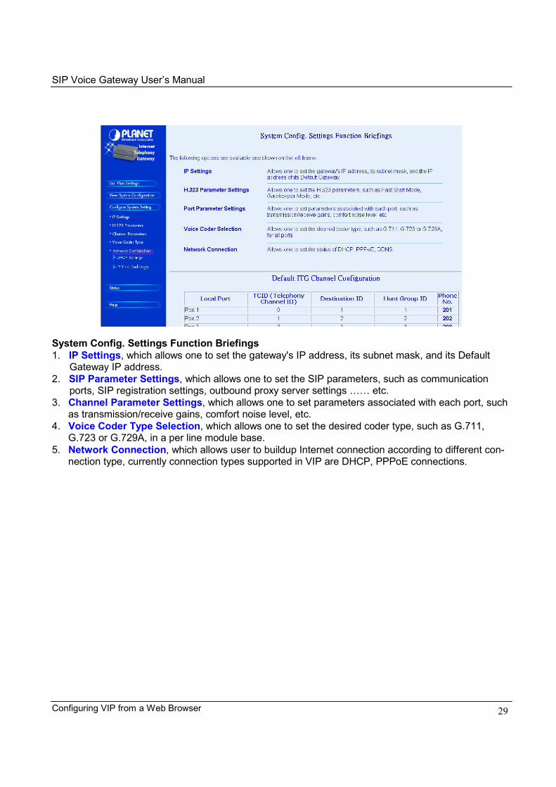
System Config. Settings Function Briefings 1. IP Settings, which allows one to set the gateway's IP address, its subnet mask, and its Default
Gateway IP address. 2. SIP Parameter Settings, which allows one to set the SIP parameters, such as communication
ports, SIP registration settings, outbound proxy server settings …… etc. 3. Channel Parameter Settings, which allows one to set parameters associated with each port, such
as transmission/receive gains, comfort noise level, etc. 4. Voice Coder Type Selection, which allows one to set the desired coder type, such as G.711,
G.723 or G.729A, in a per line module base. 5. Network Connection, which allows user to buildup Internet connection according to different con-
nection type, currently connection types supported in VIP are DHCP, PPPoE connections.

VIP User’s Manual
Configuring VIP from a Web Browser 30
4.3.1 IP Settings Please select Main Menu\Configure System Settings\IP Settings
This screen can setup your VIP IP Address, Subnet Mask and Default IP Gateway Address. These values will be valid after VIP reboot.
4.3.2 SIP Parameters Please select Main Menu\Configure System Settings\SIP Parameter Settings There are SIP Configuration Settings, Registration Server Settings, Outbound Proxy Sever configura-tions, Domain name server configurations, and Other settings..
4.3.2.1 SIP Configuration Settings Please select Main Menu\Configure System Settings\SIP Parameter Settings\SIP Configuration Settings

SIP Voice Gateway User’s Manual
Configuring VIP from a Web Browser 31
4.3.2.2 SIP Registration Server settings Please select Main Menu\Configure System Settings\SIP Parameter Settings\SIP Registration Server Settings

VIP User’s Manual
Configuring VIP from a Web Browser 32
4.3.2.2 SIP Outbound Proxy Server Settings Please select Main Menu\Configure System Settings\SIP Parameter Settings\SIP Outbound Proxy Server Settings
4.3.2.3 SIP Domain Name Server Settings Please select Main Menu\Configure System Settings\SIP Parameter Settings\SIP Domain Name Server Settings

SIP Voice Gateway User’s Manual
Configuring VIP from a Web Browser 33
4.3.2.4 Other SIP Settings

VIP User’s Manual
Command Line Interface 34
Chapter 5 Troubleshooting Tips
This section provides solutions for problems you may possibly encounter while installing and connect-ing your Internet Telephony Gateway. Power (PWR) LED is not illuminate 1. Check the power adapter connection. 2. If the power adapter or power cord is connected to the gateway, check that the cord is securely
plugged into the power socket on the rear of the console. 3. Check that the other end of the power adapter or power cord is securely plugged into the power
outlet. 4. If both ends of the power cord are properly connected and there is still no power, the gateway
might have a faulty power outlet, power adapter, or power cord. 5. Change to another power outlet or obtain another power adapter or power cord. LNK LED is not illuminate 1. Check VIP was connected correctly:
a. Powered on b. Correctly connected
2. Check if the cable connect to an end device is a standard straight through network Ethernet cable. 3. Make sure connectors at both end are securely seated. 4. Check VIP IP setting is correct There is no dial tone when pick up the phone 1. Check line module port LED illuminate 2. Check the RJ11 telephone line is connected correctly between phone set and line module port There is an out-of-service tone when dialing destination phone number 1. Check the dial plan setting (address table, hunt group table and destination table) at the destination
phone number There is no connected tone when dialing destination phone number 1. Check the IP network (Ethernet cable, Ethernet port and GW IP setting) is connected correctly 2. Check the destination VIP and phone is available Final Steps If the procedures in this section have not solved the problem, reset the gateway several times by turn-ing the power on and off. If the problem still exists, contact customer support.

SIP Voice Gateway User’s Manual
Command Line Interface 35
Chapter 6 Command Line Interface
VIP has a built-in command line interpreter and provides users a Command Line Interface (CLI). You can configure VIP by entering commands from the CLI.
You can access the CLI from a VT-100 terminal or terminal emulator connected to the RS-232 port on the front panel or through a Telnet session.
6.1 Connection through Serial Port The serial port of VIP is fixed at the following settings:
Baud rate 19,200
Number of data bit 8
Parity check None
Number of stop bit 1
Flow control None
To access VIP through the RS-232 serial port, follow the steps below:
1. Insert one end of the serial cable that came with VIP into the 9-pin RS-232 port (labeled User Console) on the front panel.
2. Insert the other end of the cable into your terminal’s serial port.
3. Configure the terminal so that settings for baud rate, number of data bit, parity check, number of stop bit and flow control capability exactly match VIP’s serial interface. (Refer to you terminal documentation for more information about setting up these features).
4. Press <Return> from the terminal.
5. VIP displays the following prompts on the terminal and you are ready to access the CLI then.
EVIP>
6.2 Connection through Telnet To use Telnet, you must have previously set the IP address using the net set ip command for VIP. Refer to the section describing the net set command later in this chapter for information about set-ting the IP address. Up to two sessions through Telnet are possible. To access VIP from a remote host with Telnet, perform the following tasks:

VIP User’s Manual
Command Line Interface 36
Task Prompt Type From the remote host, enter the telnet command followed by the IP address of VIP you want to ac-cess.
None telnet ip_addr
When VIP prompts “Login:”, enter the user name “administrator”
Login: administrator
When VIP prompts “Password:”, enter the pass-word. The default password is “123” unless a password was previously established using the net set user_pw command (Refer to the section describing net set user_pw command later in this chapter for details about the setting password).
Password: password
Upon successfully entered the password, VIP displays greeting message and the following prompts and you are ready to access the CLI commands.
ITG>
6.3 Command Help Help for commands is provided by the CLI. Type help to see a listing of the top-level commands. On most cases, if you enter a command using the wrong number of arguments or inappropriate ar-guments, the CLI will give further usage.
6.4 Designating IP Address Some commands require an IP address, which must be designated in a standard format. The IP address format is 32 bits, written as four octets separated by periods (dotted decimal format) that are made up of a network section, an optional subnet section, and a host section, as shown in the following example:
192.168.0.1
6.5 Designating Port Number Some commands require a telephony port number. VIP designates the first port telephony interface as port number 0, the 2nd port as port number 1 and so on.
SIP Voice Gateway User’s Manual
Command Line Interface 37
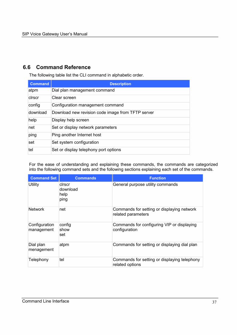
6.6 Command Reference The following table list the CLI command in alphabetic order.
Command Description atpm Dial plan management command
clrscr Clear screen
config Configuration management command
download Download new revision code image from TFTP server
help Display help screen
net Set or display network parameters
ping Ping another Internet host
set Set system configuration
tel Set or display telephony port options
For the ease of understanding and explaining these commands, the commands are categorized into the following command sets and the following sections explaining each set of the commands.
Command Set Commands Function Utility clrscr
download help ping
General purpose utility commands
Network net Commands for setting or displaying network related parameters
Configuration management
config show set
Commands for configuring VIP or displaying configuration
Dial plan menagement
atpm Commands for setting or displaying dial plan
Telephony tel Commands for setting or displaying telephony related options

VIP User’s Manual
Command Line Interface 38
6.7 Utility Commands
clrscr The clrscr command to clear the screen
Syntax Description This command has no arguments or keywords
download Use the download command to enter download mode for reading code image from a TFTP server and program it to flash memory. Refer to 0 for detailed information on how to upgrade the system software.
Syntax Description This command has no arguments or keywords
Note This command in available from serial interface. It is not available from Telnet unless the TFTP loader is version 3.00 or higher.
help The help command lists the top-level commands.
Syntax Description This command has no arguments or keywords
ping The ping command sends Internet Control Message Protocol (ICMP) echo request packets to an-other node on the network.
ping host_ip_addr ping -s host_ip_addr count/timeout Syntax description
-s Causes ping to send one datagram per second, printing one line of output for every response received.
host_ip_addr The IP address or IP alias of the host.
count (Optional) The number of packets to send
timeout (Optional) Timeout value for the ping in millisecond

SIP Voice Gateway User’s Manual
Command Line Interface 39
6.8 Network Commands
net reset Use the net reset command to reset VIP. The CLI will prompt you to confirm the command be-fore resetting VIP.
Syntax Description This command has no arguments or keywords
net set gateway ip_addr Use the net set gateway command to assign a default gateway (router) for VIP. The default gateway routes packet data outside or your IP subnet.
Syntax description
ip_addr The IP address of the default gateway. IP address of 0.0.0.0 stands for no default gateway.
Note The new setting will not take effect until VIP is reset.
net set http on|off VIP allows you enable of disable its built-in HTTP server. Use the net set http command to en-able or disable the HTTP server.
Syntax description
on Enable HTTP server. This allows users to access VIP from web browser.
off Disable HTTP server.
net set telnet on|off VIP allows you enable of disable its built-in Telnet server. Use the net set telnet command to enable or disable the Telnet server.
Syntax description
on Enable Telnet server. This allows users to access VIP from web browser.
off Disable Telnet server.
net set ip ip_addr Use the net set ip command to assign an static IP address to VIP.
Syntax description
ip_addr The IP address of VIP.
Note
VIP User’s Manual
Command Line Interface 40
The new IP address will not take effect until VIP is reset.
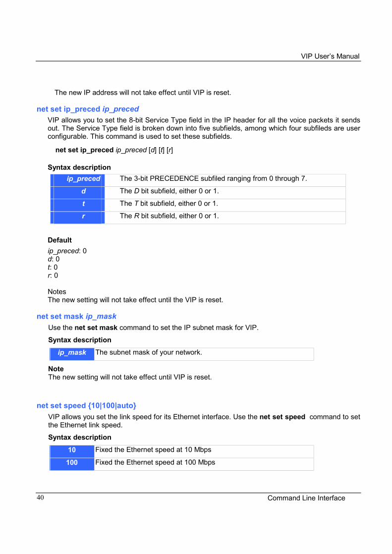
net set ip_preced ip_preced VIP allows you to set the 8-bit Service Type field in the IP header for all the voice packets it sends out. The Service Type field is broken down into five subfields, among which four subfileds are user configurable. This command is used to set these subfields.
net set ip_preced ip_preced [d] [t] [r]
Syntax description ip_preced The 3-bit PRECEDENCE subfiled ranging from 0 through 7.
d The D bit subfield, either 0 or 1.
t The T bit subfield, either 0 or 1.
r The R bit subfield, either 0 or 1.
Default ip_preced: 0 d: 0 t: 0 r: 0 Notes The new setting will not take effect until the VIP is reset.
net set mask ip_mask Use the net set mask command to set the IP subnet mask for VIP.
Syntax description
ip_mask The subnet mask of your network.
Note The new setting will not take effect until VIP is reset.
net set speed 10|100|auto VIP allows you set the link speed for its Ethernet interface. Use the net set speed command to set the Ethernet link speed.
Syntax description
10 Fixed the Ethernet speed at 10 Mbps
100 Fixed the Ethernet speed at 100 Mbps

SIP Voice Gateway User’s Manual
Command Line Interface 41
auto Enable the 10/100 Mbps auto-negoriation capablity.
net set user_pw password password Use the net set user_pw command to change the password for Telnet user.
Syntax description
password The new password. The password must be equal to or less than 7 alphanumeric characters. It must be identically typed twice for VIP to be certain about the new password.
net show The net show command displays all the network settings.
Syntax Description This command has no arguments or keywords
Example The following example shows how to display network settings:
ITG> net show <Enter> ******************* Net Parameters *******************
PPPoE = disabled
DYN DNS = enabled
DHCP client = disabled
Configured IP address = 192.168.0.99.
Configured IP subnet mask = 255.255.255.0.
Default gateway IP address = 192.168.0.253.
Current active IP address = 192.168.0.99.
Current active subnet mask = 255.255.255.0.
IP precedence = 0 0 0 0
Ethernet MAC address = 00-30-4f-00-29-20
Ethernet speed setting = 10/100 Mbps auto-negotiation
USER password = 123
HTTP server = enabled
Telnet server = enabled
Ethernet speed setting = 10/100 Mbps auto-negotiation
USER password = 123

VIP User’s Manual
Command Line Interface 42
HTTP server = enabled
Telnet server = enabled
****************************************************** ITG>
net show hwstat The net show hwstat command displays the hardware configuration of VIP.
Syntax Description This command has no arguments or keywords
Example The following example shows how to display hardware configuration:
ITG>net show hwstat <Enter> ****************** Hardware Configuration ******************
Flash: type-MX29L1611 32 sectors 64 KB/sector
RAM: 8 MB 512K x 16
LAN: 100 Mbps half duplex. Link UP
TIM slot A: type-FXO2S2 DSP-C5409 codec-PEB2466 Diag-OK
************************************************************ ITG>
net set pppoe The net set pppoe command configures PPPoE related parameters while VIP is deployed in PPPoE environment.
Syntax Description
on Turn on PPPoE client
off Turn off PPPoE client
username PPPoE connection username provided by ISP password PPPoE connection password provided by ISP
fix_ip Fixed IP address provided by ISP
net set dhcp net set dhcp command configures VIP to be DHCP client in order to obtain TCP/IP related pa-rameters from ISP while VIP is deployed in DHCP environment.
Syntax Description

SIP Voice Gateway User’s Manual
Command Line Interface 43
on Turn on DHCP client
off Turn off DHCP client
net set dyndns DDNS service can help users to find each other in dynamic/static IP environment, and enable two VIPs call each other with registered host names. To be fully functional, DNS server MUST be added into SIP configuration while DDNS service is enabled.
DDNS clients supported in VIP are www.dyndns.org and www.dtdns.com currently.
If VIP DDNS client is enabled, users MUST register a DDNS name from the sites listed above be-fore proceeding any further.
Syntax Description
on Turn on DDNS client
off Turn off DDNS client
sub commands: set dyndns add [serv_name] [host_name] [user_name] [password] Adding applied DDNS name into VIP database.
Note: if multiple DDNS names are inserted, only the first one will be updated.
Syntax Description
serv_name DDNS service server (MUST be “dyndns” or “dtdns” for now)
host_name DDNS name registered from DDNS service provider
user_name Username used to update DDNS account
password Password used to update DDNS account
set dyndns delete [host_name]|all Delete specified or all DDNS name(s) configured in VIP.
Syntax Description This command has no arguments or keywords.

VIP User’s Manual
Command Line Interface 44
6.9 Configuration Management Commands The configuration management commands allow the user to set values for system configuration pa-rameters. In addition, it provides mechanisms to allow a user to control when new parameter val-ues are put in use.
The CLI maintains three areas where the parameters are stored:
Temporary
Active
Non-volatile Storage (NVS)
When a set command is entered and processed, it changes the parameter value in the Temporary area. This does not affect current operation of VIP, which is using the values in the Active area. The config activate command moves configuration data from the Temporary area to the Active area, where it can actually be used. Thus a user can make multiple changes in the Temporary area using set commands, then put them into use with a single config activate command. (Note that the config activate command may only be used between calls, and will usually tear down any in-progress calls when invoked.)
Configuration data in the Active area is only available while VIP remains in operation. If VIP is re-set, the Active area is reloaded from the data stored in NVS. Data in the Active area may be saved to NVS by entering the config store command.
For most of the SIP parameter, settings won’t take effect until VIP reset. To ensure the SIP setting to take effect, it is recommended to reset VIP after changing the settings using the set command.
In summary:
Use set commands to make configuration parameters changes in the Temporary area
Use the config activate command to move the new values into the Active area, available for use
Use the config store command to save the new Active values in NVS
Reset VIP after changing SIP settings and storing the setting to NVS.
config activate|store|erase Use the activate command to manage the configuration data. A sequence of set command is typi-cally preceded by and/or followed by the config command for the set command to become active.
Syntax description
activate Move the configuration from temporary area to active area.
store Store the active configuration data into non-volatile storage.
erase Erase the configuration from non-volatile storage.
SIP related commands

SIP Voice Gateway User’s Manual
Command Line Interface 45
show sip The show SIP command displays the settings of the parameter that are related to SIP signaling protocol.
Syntax Description This command has no arguments or keywords
Example The following example shows how to display the SIP parameters:
ITG>show sip
SIP Addr Configuration:
UDP ctl addr = 192.168.0.99/5060
RTP data addr = 192.168.0.99/2070
Domain name server = 168.95.192.1
Info switch is off
nat_call is on
auto_reg is off
outboundproxy : None
show sip reg - Displays the information of registration
show sip cfg - Displays the configuration of registration
show sip proxy - Displays the configuration of proxy server
show sip dns_ip - Displays the configuration of DNS server
show sip info_sw - Displays the information switch
show sip auto_reg - Displays auto-registration on/off when reboot

VIP User’s Manual
Command Line Interface 46
show sip nat_call - Displays nat_call switch
show sip outboundproxy - Displays the outbound proxy
set sip reg add - used to add registration information
set sip reg add [reg_num] [expires] [#registrar] [ip] [port] name | 0 passwd | 0 ip port …
Syntax description
reg_num the phone number to be registered expires how long the reg_num is to re-register #registrar the number of registrar ip IP of the registrar port port of the registrar name [the name for authentication | 0 for no authentication] passwd [the password for authentication | 0 for no authentication]
set sip reg del - used to delete registration information
set sip reg del [reg_num]
Syntax description
reg_num the phone number to be deleted
set sip cfg - used to set the configuration of sip
set sip cfg [udp_ctl_port] [rtp_data_port]
Syntax description
udp_ctl_port <udp control port>|( 0 : default port will be used) rtp_data_port <rtp data port>|( 0 : default port will be used)
set sip proxy - used to set the configuration of sip
set sip proxy [#proxy_svr] [ proxy svr-1 nwa ] proxy svr-2 nwa …
Syntax description
#proxy_svr number of proxy server | 0 to remove existing server

SIP Voice Gateway User’s Manual
Command Line Interface 47
proxy svr nwa <ip> <port>
set sip actreg - used to send out the registration
set sip actreg
set sip dns_ip - used to set the domain name server. The IP domain should be in
numerical format set sip dns_ip [ip]
Syntax description
ip <x.x.x.x> | 0 to remove dns ip set sip info_sw - used to set the sip process information switch
set sip info_sw [on/off] set sip auto_reg
- used to set registration auto start when reboot in the condition of registration server is set
set sip auto_reg [on/off] set sip nat_call
- used to set nat_call switch on/off whether the gateway in public IP is to receive calls from the private IP or not. The default value is on.
set sip nat_call [on/off] set sip outboundproxy add - used to add outbound proxy
set sip outboundproxy add [ip/hostname] [port]
set sip outboundproxy del - used to delete outbound proxy
set sip outboundproxy del
set sip name [Registrar_ID] [name] - used to setup SIP Caller ID information. You may use "show sip reg" to show the Registrar ID and setup the corresponding Caller ID parameter. The Caller ID is the [name] field.

VIP User’s Manual
Command Line Interface 48
6.10 Voice Coding Profile Configuration Commands Coding profile is used to store coding parameters for voice and fax coding p that can be used by te-lephony port on VIP. VIP has built-in coding profiles, each having a unique profile ID and parame-ters for specific voice, fax or modem coder. Among these coding profiles, there are five may be used for voice or fax applications. The following table summarizes coding profiles available for voice and fax applications.
Coding profile ID Coder 0 G.723 6.3 kbps voice coder 1 G.729ab voice coder 2 G723 5.3 kbps voice coder 5 Proprietary fax coder 6 G.711 μ-law voice coder
10 Standard T.38 fax coder This session will introduce commands for setting the parameters for a particular coding profile. All the commands in this session are of the same syntax as follows:
set coding profile_id option [option] . . .
Syntax for the profile_id is as follows: profile_id ID of the coding profile to be modified.
6.10.1 Common Coding Profile Configuration Commands
set coding profile_id coding_type coding_type
Syntax description coding_type Type of the codcc as defined in the following table.
Parameter Description
g711_mu G.711 PCM u-law coding
g723_53 G.723.1 5.3 kbps coding
g723_63 G.723.1 6.3 kbps coding
g729ab G.729 annex A, annex B 8kbps coding
fax_t38 Fax Relay in T.38 mode Note: Modification will not take effect till save and next reboot.

SIP Voice Gateway User’s Manual
Command Line Interface 49
set coding profile_id cp_tone_detect on | off This command is used to specify a secondary level of control of call progress tone detection. If the call progress detection control for a telephony port is set to "As per coding profile" (refer to com-mand “set port port cp_tone_det_ctrl”), this parameter determines if detection is to be enabled or not.
Syntax description
on Enable call progress tone detection.
off Disable call progress tone detection.
set coding profile_id fax_tone_detect on | off This command is used to specify a secondary level of control of V.21 fax tone detection. If the fax tone detection control for a telephony port is set to "As per coding profile" (refer to command “set port port fax_tone_det_ctrl”), this parameter determines if detection is to be enabled or not. For a voice coder, fax tone detection has to be enabled, otherwise, telephony port never switches to fax mode while the voice coder is active. For a fax profile it does not matter if the fax tone detection is enabled or disabled.
Syntax description on Enable V.21 fax tone detection.
off Disable V.21 fax tone detection.
set coding profile_id usage voice | fax on | off
Syntax description
Voice
The coding profile is allowed, if the parameter that follows is “on”, for being used as voice coder. The coding profile is not allowed, if the parameter that follows is “off”, for being used as voice coder.
Fax
The coding profile is allowed, if the parameter that follows is “on”, for being used as fax coder. The coding profile is not allowed, if the parameter that follows is “off”, for being used as fax coder.
6.10.2 Voice Coding Profile Configuration Commands
set coding profile_id adaptive_playout on | off VIP has built-in voice packet buffer, which allows VIP to remove packet jitter from the incoming packet stream. VIP also implements an adaptive voice packet playback.This command is used to enable/disable the adaptive playback function for a voice coding profile.
Syntax description
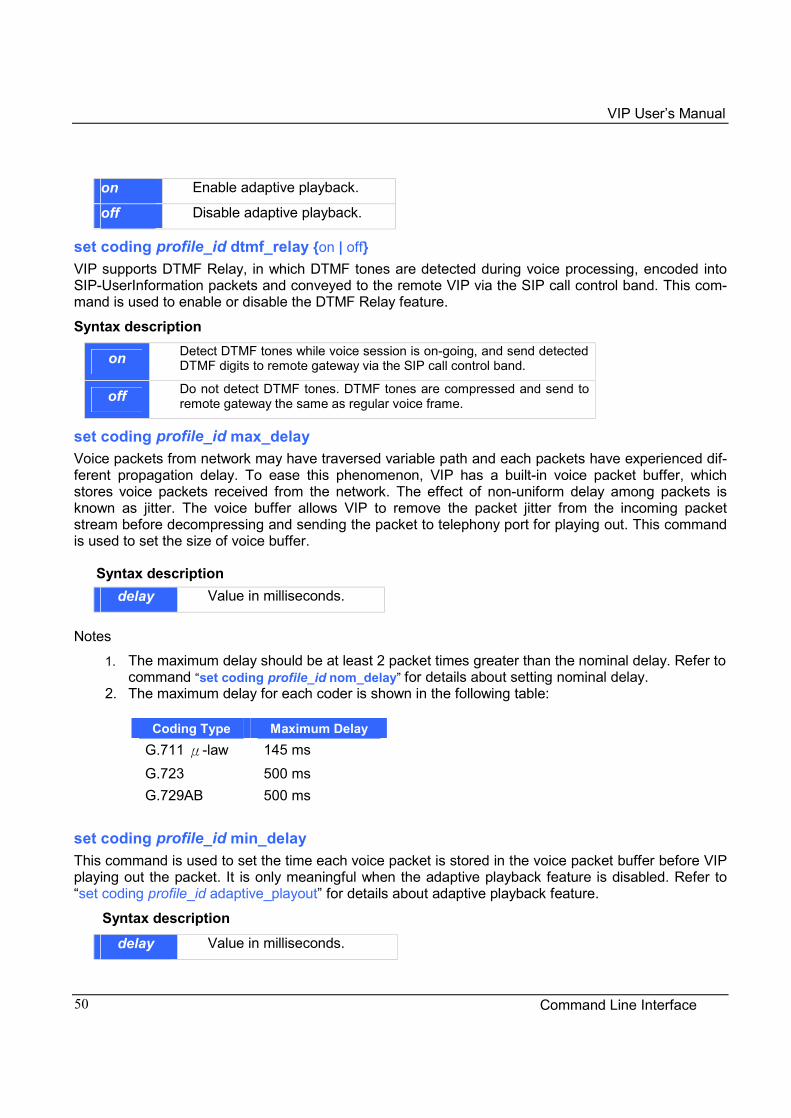
VIP User’s Manual
Command Line Interface 50
on Enable adaptive playback.
off Disable adaptive playback.
set coding profile_id dtmf_relay on | off VIP supports DTMF Relay, in which DTMF tones are detected during voice processing, encoded into SIP-UserInformation packets and conveyed to the remote VIP via the SIP call control band. This com-mand is used to enable or disable the DTMF Relay feature.
Syntax description
on Detect DTMF tones while voice session is on-going, and send detected DTMF digits to remote gateway via the SIP call control band.
off Do not detect DTMF tones. DTMF tones are compressed and send to remote gateway the same as regular voice frame.
set coding profile_id max_delay Voice packets from network may have traversed variable path and each packets have experienced dif-ferent propagation delay. To ease this phenomenon, VIP has a built-in voice packet buffer, which stores voice packets received from the network. The effect of non-uniform delay among packets is known as jitter. The voice buffer allows VIP to remove the packet jitter from the incoming packet stream before decompressing and sending the packet to telephony port for playing out. This command is used to set the size of voice buffer.
Syntax description delay Value in milliseconds.
Notes
1. The maximum delay should be at least 2 packet times greater than the nominal delay. Refer to command “set coding profile_id nom_delay” for details about setting nominal delay.
2. The maximum delay for each coder is shown in the following table:
Coding Type Maximum Delay G.711 μ-law 145 ms G.723 500 ms G.729AB 500 ms
set coding profile_id min_delay This command is used to set the time each voice packet is stored in the voice packet buffer before VIP playing out the packet. It is only meaningful when the adaptive playback feature is disabled. Refer to “set coding profile_id adaptive_playout” for details about adaptive playback feature.
Syntax description
delay Value in milliseconds.

SIP Voice Gateway User’s Manual
Command Line Interface 51
set coding profile_id nom_delay
Syntax description Delay Value in milliseconds.
set coding profile_id vad on | off This command is used to enable/disable the Voice Activity Detector (VAD) for a coding profile.
Syntax description
On Enable VAD.
Off Disable VAD.
set coding profile_id vad_thresh This command is used to set threshold level for the VAD for a coding profile.
Syntax description threshold Value in dBm, ranging from –20 to +10.
set coding profile_id vif This command is used to set the size of the Voice Information Field (VIF), in bits, for a voice coder.
Syntax description Coding type Sampling time VIF
G.711 μ-law 10 ms 640 20 ms 1,280 30 ms 1,920
G.723 30 ms 192 60 ms 384
G.729AB 10 ms 80 20 ms 160 30 ms 240 40 ms 320 50 ms 400 60 ms 480
Note:

VIP User’s Manual
Command Line Interface 52
Size of the Voice Information Field (VIF), in bits, for a voice coder are related to the coding type and the rate the voice coder samples a voice frame (the packet time), as shown in the table above. VIF sizes of a coder of values other than those shown in the table are not valid.
6.11 Dial Plan Management Commands Among the command sets supported by the CLI, the dial plan management commands are the most sophisticated. Some of the dial plan management commands are only allowed when VIP is in the atpm table update state. For ease of explaining, this command set is further categorized into several sub command sets.
Sub command set
Purposes
Commands
atpm table up-date state re-
quired? Database update control
Instruct VIP to start or stop atpm table update state. Store/restore atpm tables
to/from non-volatile storage Purge atpm tables Erase dial plan database
from non-volatile storage
atpm req atpm done atpm re-store atpm store atpm purge atpm erase
No No Yes No Yes No
Destination table management
Manage atpm destination table atpm dadd atpm ddel atpm dfind atpm dlist
Yes Yes No No
Hunt group table management
Manage atpm hunt group table atpm hadd atom hdel atpm hfind atpm hlist
Yes Yes No No
Address table management
Manage atpm address table atpm aadd atpm adel atpm afind atpm alist
Yes Yes No No
System Manage atpm system configura-tion
atpm slist atpm sys
No Yes
The following sections describe each sub command set and the commands.

SIP Voice Gateway User’s Manual
Command Line Interface 53
Database Update Control Commands
atpm done The atpm done command ends the atpm table update session and re-enables the address transla-tion.
Syntax description This command has no arguments or keywords
atpm erase The atpm erase command erases the dial plan database from the non-volatile memory.
Syntax description This command has no arguments or keywords
atpm purge all|addr|dest|hunt Use the atpm purge command to delete all entries from the atpm tables.
Syntax description
all Delete all entries from atpm ddress, destination and hunt group ta-bles.
addr Delete all entries from atpm address table.
dest Delete all entries from atpm destination table.
hunt Delete all entries from atpm hunt group table.
atpm req The atpm req command starts the atpm table update session. Upon starting the atpm table update session, the ATPM address translation is disabled, hence no phone call can be made, until a atpm done command is issued.
Syntax description This command has no arguments or keywords
atpm restore The atpm restore command restores the whole dial plan from non-volatile storage to the atpm ad-dress, destination and hung group tables.
Syntax description This command has no arguments or keywords

VIP User’s Manual
Command Line Interface 54
atpm store [erase] The atpm store command store all atpm tables into non-volatile memory.
Syntax description
erase (Optional) Erase the non-volatile before storing the dial plan data-base. This option is not recommended except the very first time you use the atpm store command.
Hunt Group Table Management Commands
atpm hadd hunt_group_id 1|2 dest_id [desi_id2] … Use the atpm hadd command to add an entry into the atpm hunt group table.
Syntax description
hunt_group_id Hunt group ID. For each hunt group, you need to assign it a unique identifier between 1 and 65536.
1 Hunt type 1. Hunt type 1 hunts destination within a hunt group starting from the destination member just after the last used member.
2 Hunt type 2. Hunt type 2 hunts destination within a hunt group starting from the first destination member.
dest_id1 ID of the first destination member in the hunt group.
dest_id2 dest_id3 …
(Optional)List of ID’s of additional destination members in the hunt group.
Example The following example shows how to group destination 1, 2, 3 and 4 into a hunt group, assign it hunt group ID 10, and specify hunt type 2 for this hunt group.
ITG>atpm hadd 10 2 1 2 3 4<Enter>
atpm hdel hunt_group_id The atpm hdel command deletes an entry from the atpm hunt group table.
Syntax description
hunt_group_id ID of the hunt group to be deleted from the hunt group table.
atpm hfind hunt_group_id The atpm hfind finds and display an entry in the hunt group table.

SIP Voice Gateway User’s Manual
Command Line Interface 55
Syntax description
hunt_group_id ID of the hunt group to be displayed.
atpm hlist The atpm hlist display all entries in the hunt group table.
Syntax description This command has no arguments or keywords
Example
ITG>atpm hlist Group id Type #Members Member ids ------------------------------------------------------------------- 1 2 1 1 2 2 1 2 3 2 1 3 4 2 1 4 5 2 1 5 6 2 1 6 7 2 1 7 8 2 1 8 11 2 1 11 OK ITG>
Address Table Management Commands
atpm aadd tel# min_digits max_digits hunt_group_id prefix_strip_len [prefix#] Use the atpm aadd command to add an entry into the atpm address table.
Syntax description
tel# Telephone number to match. This is only part of the total dialed string.
min_digits Minimum number of digits to be collected before the ATPM starting matching the dialed string with entries in the address table.
max_digits Maximum number of digits to be collected before the ATPM starting matching the dialed string with entries in the address table.
hunt_group_id Hung group ID for this telephone number
pre-fix_strip_len
The number of digits to be stripped at the beginning of the collected dial string before forwarding the string to the destination.
prefix# (Optional) Digit to be added before the beginning of the collected dial string before forwarding it to the destination.

VIP User’s Manual
Command Line Interface 56
atpm adel tel# The atpm adel command deletes an entry from the atpm address table.
Syntax description
tel# Number of a previously added entry to be deleted from the atpm ad-dress table.
atpm afind tel# The atpm afind finds and display an entry in the address table.
Syntax description
tel# Number of a previously added entry in the atpm table to be displayed.
atpm alist The atpm alist displays all entries in the address table.
Syntax description This command has no arguments or keywords
Example
ITG>atpm alist Address Hunt Min Max Prefix Prefix Entry Grp_Id Digits Digits strip Address 201 1 1 3 3 None 202 2 1 3 3 None 203 3 1 3 3 None 204 4 1 3 3 None ITG>atpm done OK ITG>
System Commands
atpm slist The atpm slist displays the atpm system table.
Syntax description This command has no arguments or keywords
Example

SIP Voice Gateway User’s Manual
Command Line Interface 57
ITG>atpm slist System Info: Total dial time = 30000ms, First digit wait = 10000ms, Interdigit wait = 5000ms, Dial term digit = None OK ITG>
atpm sys dial_time 1st_digit_wait inter_digit_wait [dial_term_digit] Use the atpm sys command to set the time constraints for collection of dial digits.
Syntax description
dial_time The maximum time, in millisecond, allowed for entry of the entire string of dial digits. At expiration, ATPM starts address lookup.
1st_digit_wait The maximum time, in millisecond, allowed between off-hook and when the first dial digit is entered. At expiration, ATPM con-siders address lookup to fail.
inter_digit_wait The maximum time allowed between entry of each digit after the previous digit. At expiration, ATPM starts address lookup.
dial_term_digitr (Optional) End of the dial string is declared when the digit is en-tered.
6.12 Tel Commands
tel show pcm_gain_level The tel show pcm_gain_level command to display the gain level setting of the PCM codec’s re-ceive channel.
Syntax Description This command has no arguments or keywords
tel show port [port#] The tel show port command displays the hook state of a telephony port.
Syntax Description
port# Number of the port.
Default If the port number is not specified, the CLI displays hook state of all telephony ports.
tel show ring_freq The tel show ring_freq command to displays the frequency of the ring signal that VIP sends to FXS ports..

VIP User’s Manual
Command Line Interface 58
tel set pcm_gain_level 1|2|3|4|5 The FXO ports might be connected to central office switch or PBX via local loop which may of as long as several miles. For compensating signal distortion in the local loop, VIP’s PCM codec is de-signed in such a way that users might adjust it gain level before transmitting analog signal to the lo-cal loop. The tel set pcm_gain_level command is used to set the gain level for the PCM codec for compensating signal loss in the local loop.
Syntax Description
1 Set gain level to –1 dB
2 Set gain level to 0 dB
3 Set gain level to +1 dB
4 Set gain level to +2 dB
5 Set gain level to +3 dB
Default The default setting is -1 dB.
Note The PCM gain level setting is only meaningful to FXO ports. It is not applicable to FXS ports.
tel set ring_freq 1|2|3|4 Use the tel set ring_freq command to set the frequency of the ringer VIP uses to ring a FXS port.
Syntax Description
1 Set ring freq to 17 Hz
2 Set ring freq to 20 Hz
3 Set ring freq to 25 Hz
4 Set ring freq to 50 Hz
VIP User’s Manual
Command Line Interface 59
Chapter 7 Upgrading and resetting VIP VIP-450 is able to have system functionality enhancement via software upgrade. This must be oper-ated in upgrade mode. In firmware upgrade mode, limited commands allow users to read new revision codes from a remote TFTP server and write into the built-in flash non-volatile storage.
To enter download mode, either Telnet or Console (RS-232) connection can take the job, and a TFTP server is required by VIP to complete firmware upgrade process.
7.1 Firmware upgrade To switch from normal operation mode to download mode, use the download CLI command.
ITG> download <Enter>
Note: To be able to switch to download mode from Telnet session, TFTP loader on VIP must be ver-sion 3.00 or higher. To upgrade to firmware version 3.03 or above, bootloader version 4.01 or above is required.
After download command is inserted, VIP will terminate all on-going calls, reset and enter firmware download mode. If you enter download mode from Telnet session. The Telnet session will be termi-nated too. You need to re-connect to VIP from Telnet client to be able to access the firmware download mode.
Before going any further, please note: NEVER, NEVER TURN OFF POWER while firmware up-grade is working in progress!! (Please ensure power supply is stable before firmware upgrade is executed.) TFTP server is required to complete VIP series firmware upgrade process; there are various TFTP server software on the market, please utilize the existing software or find a new one on the net to com-plete upgrade process. (In this chapter, 3CDeamon TFTP server was installed for demonstration.) TCP/IP Configuration: Computer installed with TFTP server: 192.168.0.7 VIP: 192.168.0.1 Note: If a Telnet connection is built behind NAT environment, TCP port 69 MUST be reserved for data
communication.
Console connection
VIP (192.168.0.1)
Computer equipped with TFTP Server IP: 192.168.0.7

VIP User’s Manual
Command Line Interface 60
TFTP server configuration 1. Execute TFTP server program, assign firmware file location, and save the path if necessary. (In this
sample datagram, the file is assigned in c:\) (This part might vary on different kind of TFTP server.)
2. Allocate VIP firmware file in the directory, and apply the modification (if required). Note: TCP port 69 is required for TFTP access. VIP configuration: Telnet session
a) Under Telnet firmware download mode, the user name: eitg; password: 123 (password may vary because of user’s configuration) is used for logging on VIP
b) Under ITG> prompt, insert command: download to enter VIP firmware upgrade mode. c) Insert command: “start” and answer questions on screen to proceed firmware upgrade. d) When VIP prompts downloading firmware file into EEPROM, insert “y” to continue. e) Wait till firmware is fully loaded into VIP, insert “quit” to leave firmware upgrade mode and an-
swer “y“ to reboot machine when VIP prompts for restart.

SIP Voice Gateway User’s Manual
Command Line Interface 61
ITG>download ============================== WARNING ============================== * Entering download mode will hang up all telephone connections * * and all the configuration settings will lose. * * Be certain all the configuration settings have been saved. * ======================================================================= Do you want to enter download mode now (y/n)? [n] y Boot loader V4.12 Loading TFTP loader..................... ** Internet Telephony Gateway TFTP Loader Ver 4.10 ** EITGLoader>start IP address of the TFTP server? [192.168.0.254] 192.168.0.7 File name? xyz123.imz Starting download file: xyz123.imz ........................................................................................................................................................................................................... Download complete, file size = 833004 Application code downloaded successfully Do you want to write downloaded image to flash EEPROM (y/n)? [y] y Press <Enter> to start flash EEPROM programming Flash EPROM programming on-going, BE CERTAIN NOT TO TURN POWER OFF... Flash sector no. 4 write done Flash sector no. 5 write done Flash sector no. 6 write done Flash sector no. 7 write done Flash sector no. 8 write done Flash sector no. 9 write done Flash sector no. 10 write done Flash sector no. 11 write done Flash sector no. 12 write done Flash sector no. 13 write done Flash sector no. 14 write done Flash sector no. 15 write done Flash sector no. 16 write done Flash EEPROM programming completed All sectors programmed successfully Download another file (y/n)? [n] n EITGLoader>quit Do you want to restart the system now (y/n)? [n] y

VIP User’s Manual
Command Line Interface 62
Console session a) Connect VIP through the 9-pin RS232 female console (No password required)
Under ITG> prompt, insert command: download to enter VIP firmware upgrade mode. b) Insert command: “start” and answer questions on screen to proceed firmware upgrade. c) When VIP prompts downloading firmware file into EEPROM, insert “y” to continue. d) Wait till firmware is fully loaded into VIP, insert “quit” to leave firmware upgrade mode and an-
swer “y“ to reboot machine when VIP prompts for restart.
ITG>download ============================== WARNING ============================== * Entering download mode will hang up all telephone connections * * and all the configuration settings will lose. * * Be certain all the configuration settings have been saved. * ======================================================================= Do you want to enter download mode now (y/n)? [n] y Boot loader V4.12 Loading TFTP loader..................... ** Internet Telephony Gateway TFTP Loader Ver 4.10 ** EITGLoader>start IP address of the TFTP server? [192.168.0.254] 192.168.0.7 File name? xyz123.imz Starting download file: xyz123.imz ........................................................................................................................................................................................................... Download complete, file size = 833004 Application code downloaded successfully Do you want to write downloaded image to flash EEPROM (y/n)? [y] y Press <Enter> to start flash EEPROM programming Flash EPROM programming on-going, BE CERTAIN NOT TO TURN POWER OFF... Flash sector no. 4 write done Flash sector no. 5 write done Flash sector no. 6 write done Flash sector no. 7 write done Flash sector no. 8 write done Flash sector no. 9 write done Flash sector no. 10 write done Flash sector no. 11 write done Flash sector no. 12 write done Flash sector no. 13 write done Flash sector no. 14 write done Flash sector no. 15 write done Flash sector no. 16 write done Flash EEPROM programming completed All sectors programmed successfully Download another file (y/n)? [n] n EITGLoader>quit Do you want to restart the system now (y/n)? [n] y

SIP Voice Gateway User’s Manual
Command Line Interface 63
Trouble Shooting Tips If following error (TFTP timeout error) occurs: Possibility:
a) Network connection is not correctly configured è check if cable is securely connected. è check if TFTP server IP address is correctly configured è check if TCP port 69 is available for TFTP connection è if firmware upgrade is processed remotely, a fast connection between VIP and TFTP server
is required (ping response time <300 ms) During firmware upgrade, ”protocol error detected” displays on the screen.
a) In most circumstances, this error occurs while requested firmware file cannot be found on TFTP server.
Possibility: à check if the firmware file is correctly located in assigned folder. à check if TFTP server supports long file name format. à check if firmware file name is correctly inserted à check system log on TFTP server if there is error message for trouble shooting.
** Internet Telephony Gateway TFTP Loader Ver 4.10 ** EITGLoader>start IP address of the TFTP server? [192.168.0.7] File name? xyz123.imz Starting download file: xyz123.imz TFTP device open failed. - Protocol error detected. Download another file (y/n)? [n]
** Internet Telephony Gateway TFTP Loader Ver 4.10 ** EITGLoader>start IP address of the TFTP server? [192.168.0.7] File name? xyz123.imz Starting download file: xyz123.imz TFTP device open failed. - TFTP server timeout while waiting for a response from the client. Download another file (y/n)? [n]

VIP User’s Manual
Command Line Interface 64
7.2 CLI Commands in Download Mode Under download mode, the CLI supports the following commands:
Command Description help Display help screen
quit Terminate download mode, switch to normal operation mode.
set Change IP parameter
start Start downloading code from TFTP server
The following section describes each of the commands.
help The help command lists the top-level commands.
quit The quit command is used to terminate the download mode and return to normal operation mode. Syntax Description This command has no arguments or keywords Note Switching mode from Telnet session will terminate current active session. You’ll need to connect to VIP again to be able to access the CLI.
set ip ip_addr Use the set ip command to assign an static IP address to VIP.
Syntax description
ip_addr The IP address of VIP.
Note The new IP address will not take effect until VIP is reset.
set gateway ip_addr Use the set gateway command to assign a default gateway (router) for VIP. The default gateway routes packet data outside or your IP subnet.
Syntax description
ip_addr The IP address of the default gateway. Default value: 0.0.0.0
Note The new setting will not take effect until VIP is reset.

SIP Voice Gateway User’s Manual
Command Line Interface 65
set mask ip_mask Use the set mask command to set the IP subnet mask for VIP.
Syntax description
ip_mask The subnet mask of your network.
Note The new setting will not take effect until VIP is reset.
start Use the start command to start downloading code from TFTP server. VIP will prompt you for the IP address of the TFTP server and the file to download.
7.3 Restore default configuration If there is system re-organization, firmware upgrade or improper parameters are loaded in VIP-450, restoring factory default settings may help you to restore initial state of machine and restart configura-tion. Following are steps loading VIP series default parameters: Note: restore process in this session only can be applied to firmware version 3.xx)
System configuration default parameters a) Logon VIP via telnet or console connection, and insert command: config erase b) After this command, VIP pops up a warning message and prompts for confirmation. c) Press ”y” to erase current system configuration parameters, d) Enter net reset to reboot and load the default system parameters into machine. e) Log on VIP, and insert command: config store to load factory default parameters into VIP.

VIP User’s Manual
Command Line Interface 66
A sample is attached below for reference.
ITG>config erase The system configuration data will be erased from non-volatile storage permanently. Are you sure to erase it (y/n)? [n] y System configuration records erased from flash ITG>net reset ============================== WARNING ============================== * Restarting the system will hang up all telephone connections * * and all the configuration settings will lose. * * Be certain all the configuration settings have been saved. * ======================================================================= Do you want to restart the system now (y/n)? [n] y Boot loader V4.12 Mem 16b 16M Loading application code............................................................................................................. ******* Internet Telephony Gateway (PLA) Version s1.0 ******* ****************** Hardware Configuration ****************** Flash: type-MX29L1611 32 sectors 64 KB/sector RAM: 8 MB 512K x 16 LAN: auto-negotiation on-going. Link DOWN TIM slot A: type-FXO2S2 DSP-C5409 codec-PEB2466 Diag-OK ************************************************************ ITG>config store OK ITG>

SIP Voice Gateway User’s Manual
Command Line Interface 67
Dialplan configuration default parameters: a) Log on VIP via telnet or console connection. b) At the ITG prompt, insert following commands:
ITG>atpm erase ITG>net reset (Answer ”y” to reboot machine.)
After rebooting, logon VIP. At the ITG> prompt, insert: atpm store to restore Dialplan default value into VIP.
A sample is attached below for reference.
ITG>atpm erase The dial plan will be erased from non-volatile storage permanently. Are you sure to erase it (y/n)? [n] y Dial plan erased from flash OK ITG>net reset ============================== WARNING ============================= * Restarting the system will hang up all telephone connections * * and all the configuration settings will lose. * * Be certain all the configuration settings have been saved. * ==================================================================== Do you want to restart the system now (y/n)? [n] y Boot loader V4.12 Mem 16b 16M Loading application code........................................................................................................................ ******* Internet Telephony Gateway (PLA) Version s1.0 ******* ****************** Hardware Configuration ****************** Flash: type-MX29L1611 32 sectors 64 KB/sector RAM: 8 MB 512K x 16 LAN: auto-negotiation on-going. Link DOWN TIM slot A: type-FXO2S2 DSP-C5409 codec-PEB2466 Diag-OK ************************************************************ ITG>No dial plan info can be found in the Flash, the default dial plan is used but NOT saved. OK ITG>atpm store OK


VIP User’s Manual
Technical Specifications 69
Appendix A Technical Specifications
A.1 VIP Technical Specifications
Telephony Interface Module support
VIP-450: 2 ports loop start FXO, 2 ports loop start FXS
VIP-050: 4 ports loop start FXO, 4 ports loop start FXS
(Up to two modules per unit)
Network Interface Ports 1 10/100Base-T, auto sensing, RJ45
Voice codec support G.711 PCM 64kbps (A-law and μ-law) G.723.1A ACELP/M-MLQ (5.3, 6.3kbps) G.729AB CS-ACELP (8kbps)
Fax ITU-T V.21, V.27ter, V.29, V.33 and V.17
Fax over IP protocol T.38 Proprietary low bandwidth protocol
Echo cancellation G.168 compliant, 16 ms tail length
Simultaneous connection VIP-450: 4 channels voice/fax
VIP-050: 8 channels voice/fax
Voice processing
Voice activity detection DTMF detection/generation Echo cancellation Comfort noise generation Call progress detection Gain control
Call control SIP 2.0 (RFC3261)
Management Built HTTP server allowing management from web browser Command line interface allowing management from VT-100 terminal or Telnet client
Software upgrade Flash memory and built-in TFTP allowing software upgrade via net-work
Power VIP-450: AC-to-DC power supply, 90-260 VAC, 50-60 Hz
VIP-050: 90-240 VAC, 20 Watts, 50-60 Hz
Environmental Operating temperature: 0o to 45o C (32o to 113o F) Storage temperature: -10o to 65o C (-4o to 149o F) Humidity: 10% to 85% (non-condensing)
Dimension (L x W x D) VIP-450: 150 x 220 x 44 (mm)
VIP-000: 445 x 275 x 44 (mm)

VIP User’s Manual
Technical Specifications 70
Compliances
EMI FCC Part 15 Class A EN55022 Class A (CISPR-22 Class A) VCCI Class A CE
Safety UL 1950 CE
Mounting VIP-450: Desktop
VIP-000: Desktop or 19” rack mounting
A.2 Console Port The console port uses a DB-9 RS-232 connector. The supplied straight-through RS-232 cable con-nects the console port of VIP to a console PC or terminal. Pinout for the port is described in the fol-lowing table.
DB-9 pin Signal
1 Not connected 2 TxD 3 RxD 4 Not connected 5 Ground 6 Not connected 7 Not connected 8 Not connected 9 Not connected
A.3 LAN Port The 10/100 LAN port use standard RJ-45 connector and Ethernet pinouts. The following diagram and table show the pinout on the port connector. When connecting the LAN port to switches or re-peaters, you must use a straight-through cable.
RJ45 pin Signal
1 RxD+ 2 RxD- 3 TxD+ 4 Not connected 5 Not connected
1 2 3 4 5 6 7 8

SIP Voice Gateway User’s Manual
Technical Specifications 71
6 TxD- 7 Not connected 8 Not connected
A.4 FXO Port Pin Assignments The FXO Telephony Interface Module has 4 RJ11C/W modular jacks. The following diagram and table show the assignments of the pin for the RJ11 port.
RJ-11 pin Signal 1 Not connected 2 Tip 3 Ring 4 Not connected
A.5 FXS Port Pin Assignments The FXS Telephony Interface Module has 4 RJ11C/W modular jacks. The following diagram and table show the assignments of the pin for the RJ11 port.
RJ-11 pin Signal
1 Not connected 2 Tip 3 Ring 4 Not connected
1 2 3 4
1 2 3 4

VIP User’s Manual
Technical Specifications 72
A.6 FXO Card Technical Specifications
Signaling: Loop Start / DTMF
No. of channels: 4
Interface Connectors: 4 RJ-11 2-pin modular jacks.
Line Impedance : 600 Ω 900 Ω
Insertion Loss: 2 dB nominal.
Frequency Response: 300Hz ~ 3400Hz +/- 2dB w.r.t. 1004Hz.
Return Loss: ≥ 18 dB
Input Level adjustment: -6 dB to +6 dB
Output Attenuation: 0 dB to 13 dB
Longitudinal Balance: ≥ 45 dB
A.7 FXS Card Technical Specifications
Signaling: Loop Start / DTMF
No. of channels: 4
Interface Connectors: 4 RJ-11 2-pin modular jacks.
Line Impedance : 600 Ω 900 Ω
Insertion Loss: 2 dB nominal.
Frequency Response: 300Hz ~ 3400Hz +/- 2dB w.r.t. 1004Hz.
Return Loss: ≥ 18 dB
Input Level adjustment: -6 dB to +6 dB
Output Attenuation: 0 dB to 13 dB
Longitudinal Balance: ≥ 45 dB
Loop Current: 25mA nominal
Ring Voltage: 50Vrms Nominal
Ringing Tone: 16.67Hz, 20Hz(default), 25Hz or 50Hz
VIP User’s Manual
CLI Commands 73
Appendix B CLI Commands
B.1 Normal Mode Commands Command Description
atpm aadd Add an entry to the address table
atpm adel Delete an entry from the address table
atpm afind Find and display an entry in the address tble
atpm alist Display all entries in the address table
atpm dadd Add an entry to the destination table
atpm ddel Delete an entry from the destination table
atpm dfind Find and display an entry in the destination atble
atpm dlist Display all entries in the address table
atpm hadd Add an entry to the hunt group table
atpm hdel Delete an entry from the hunt group table
atpm hfind Find and display an entry in the hunt group tble
atpm hlist Display all entries in the hunt group table
atpm done End the atpm table update session
atpm erase Erase all atpm tables from NVS
atpm purge Purge entries from atpm table(s)
atpm req Start atpm table update session
atpm restore Restore atpm tables from NVS
atpm store Store atpm tables into NVS
atpm slist Display atpm system parameters
atpm sys Set atpm system parameters
config activate Move the configuration from temporary area to active area.
config erase Erase the configuration from NVS
config store Store the active configuration data into NVS
clrscr Clear screen
download Switch to download mode
help Display help screen
VIP User’s Manual
CLI Commands 74
net reset Reset the system
net set gateway Set default gateway’s IP address
net set http Turn on/off HTTP server
net set ip Set IP address
net set ip_preced Set IP precedence bits
net set mask Set IP subnet mask
net set speed Select Ethernet link speed
net set user_pw Set password
net show Display IP parameters
net show hwstat Display hardware status
ping Send ICMP echo request to another host
show sip Display SIP parameter settings
show version Show software versions
set sip Setup SIP related parameters
tel show pcm_gain_level
Display gain level setting of the PCM codec’s receive channel.
tel show port Display hook state for a telephony port
tel show ring_freq Show ringer’s frequency
tel set pcm_gain_level Set gain level for the PCM codec’s receive channel
tel set ring_freq Set ringer’s frequency
B.2 Download Mode Commands Command Description
help Display help screen
quit Switch to normal operation mode
set gateway Set default gateway ‘s IP address
set ip Set IP address
net set mask Set IP subnet mask
start Start downloading file
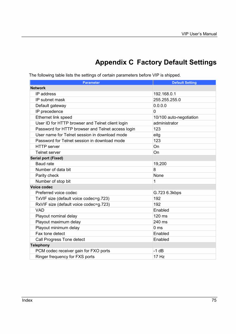
VIP User’s Manual
Index 75
Appendix C Factory Default Settings The following table lists the settings of certain parameters before VIP is shipped.
Parameter Default Setting Network
IP address 192.168.0.1 IP subnet mask 255.255.255.0 Default gateway 0.0.0.0 IP precedence 0 Ethernet link speed 10/100 auto-negotiation User ID for HTTP browser and Telnet client login administrator Password for HTTP browser and Telnet access login 123 User name for Telnet session in download mode eitg Password for Telnet session in download mode 123 HTTP server On Telnet server On
Serial port (Fixed) Baud rate 19,200 Number of data bit 8 Parity check None Number of stop bit 1
Voice codec Preferred voice codec G.723 6.3kbps TxVIF size (default voice codec=g.723) 192 RxVIF size (default voice codec=g.723) 192 VAD Enabled Playout nominal delay 120 ms Playout maximum delay 240 ms Playout minimum delay 0 ms Fax tone detect Enabled Call Progress Tone detect Enabled
Telephony PCM codec receiver gain for FXO ports -1 dB Ringer frequency for FXS ports 17 Hz