
Internet Indirection Infrastructure Ion Stoica UC Berkeley.
25
Internet Indirection Infrastructure Ion Stoica UC Berkeley
-
date post
20-Dec-2015 -
Category
Documents
-
view
228 -
download
2
Transcript of Internet Indirection Infrastructure Ion Stoica UC Berkeley.
Internet Indirection Infrastructure
Ion StoicaUC Berkeley

2
Motivations
• Today’s Internet is built around a unicast point-to-point communication abstraction:– Send packet “p” from host “A” to host “B”
• This abstraction allows Internet to be highly scalable and efficient, but…
• … not appropriate for applications that require other communications primitives:– Multicast – Anycast – Mobility– …
3
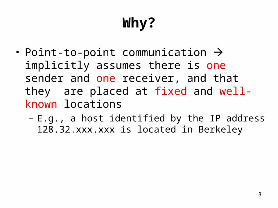
Why?
• Point-to-point communication implicitly assumes there is one sender and one receiver, and that they are placed at fixed and well-known locations– E.g., a host identified by the IP address
128.32.xxx.xxx is located in Berkeley
4
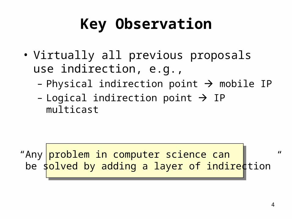
Key Observation
• Virtually all previous proposals use indirection, e.g., – Physical indirection point mobile IP– Logical indirection point IP multicast
“Any problem in computer science can be solved by adding a layer of indirection”

5
Our Solution
• Use an overlay network to implement this layer– Incrementally deployable; don’t need to change IP
Build an efficient indirection layer
on top of IP
IP
TCP/UDP
Application
Indir.layer

6
Internet Indirection Infrastructure (i3)
• Each packet is associated an identifier id• To receive a packet with identifier id,
receiver R maintains a trigger (id, R) into the overlay network
Sender
id Rtrigger
iddata
Receiver (R)
iddata
Rdata

7
Service Model
• API– sendPacket(p);– insertTrigger(t);– removeTrigger(t) // optional
• Best-effort service model (like IP)• Triggers periodically refreshed by end-
hosts• ID length: 256 bits

8
Mobility
• Host just needs to update its trigger as it moves from one subnet to another
Sender
Receiver(R1)
Receiver(R2)
id R1id R2
9
iddata
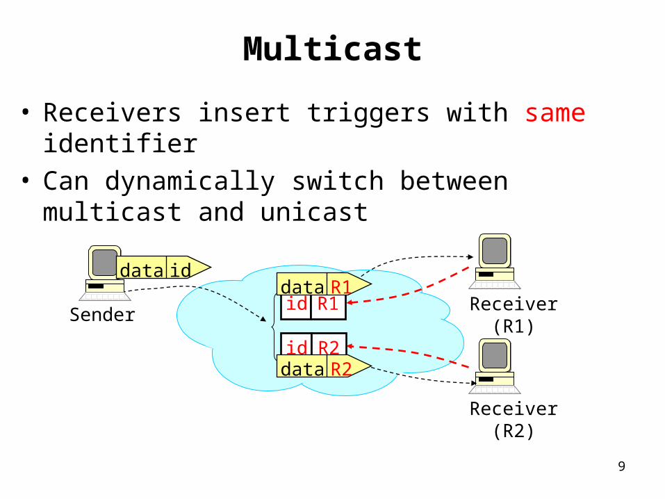
Multicast
• Receivers insert triggers with same identifier• Can dynamically switch between multicast
and unicast
Receiver (R1)id R1
Receiver (R2)
id R2
Sender
R1data
R2data
iddata

10
Anycast
• Use longest prefix matching instead of exact matching– Prefix p: anycast group identifier
– Suffix si: encode application semantics, e.g., location
Sender
Receiver (R1)p|s1 R1
Receiver (R2)p|s2 R2
p|s3 R3
Receiver (R3)
R1datap|adata p|adata

11
Service Composition: Sender Initiated
• Use a stack of IDs to encode sequence of operations to be performed on data path
• Advantages– Don’t need to configure path– Load balancing and robustness easy to achieve
SenderReceiver (R)
idT Tid R
Transcoder (T)
T,iddata
iddata
Rdata
idT,iddata idT,iddata

12
Service Composition: Receiver Initiated
• Receiver can also specify the operations to be performed on data
Receiver (R)
id idF,R
Firewall (F)
Sender idF F
idF,Rdata
Rdata
F,Rdata
iddata iddata

13
Quick Implementation Overview
• ID space is partitioned across infrastructure nodes– Each node responsible for a region of ID
space
• Each trigger (id, R) is stored at the node responsible for id
• Use Chord to route triggers and packets to nodes responsible for their IDs– O(log N) hops

14
Example
• ID space [0..63] partitioned across five i3 nodes• Each host knows one i3 node• R inserts trigger (37, R); S sends packet (37, data)
[42..3]
[4..7]
[8..20]
[21..35][36..41]Sender (S)
Receiver (R)
37 R
37data
Rdata

15
Sender (S)
Optimization: Path Length
• Sender/receiver caches i3 node mapping a specific ID
• Subsequent packets are sent via one i3 node
[42..3]
[4..7]
[8..20]
[21..35][36..41]
37 R
37data
Rdatacache node Receiver (R)
16
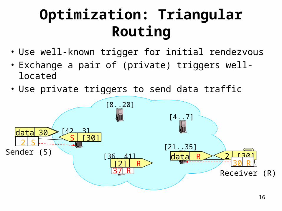
Optimization: Triangular Routing
• Use well-known trigger for initial rendezvous• Exchange a pair of (private) triggers well-located• Use private triggers to send data traffic
[42..3]
[4..7]
[8..20]
[21..35][36..41]
37 RR[2]
2 S37[2]
2 [30]30 R
S [30]30data
Rdata
Receiver (R)
Sender (S)
17
Outline
• OverviewSecurity• Discussion
18
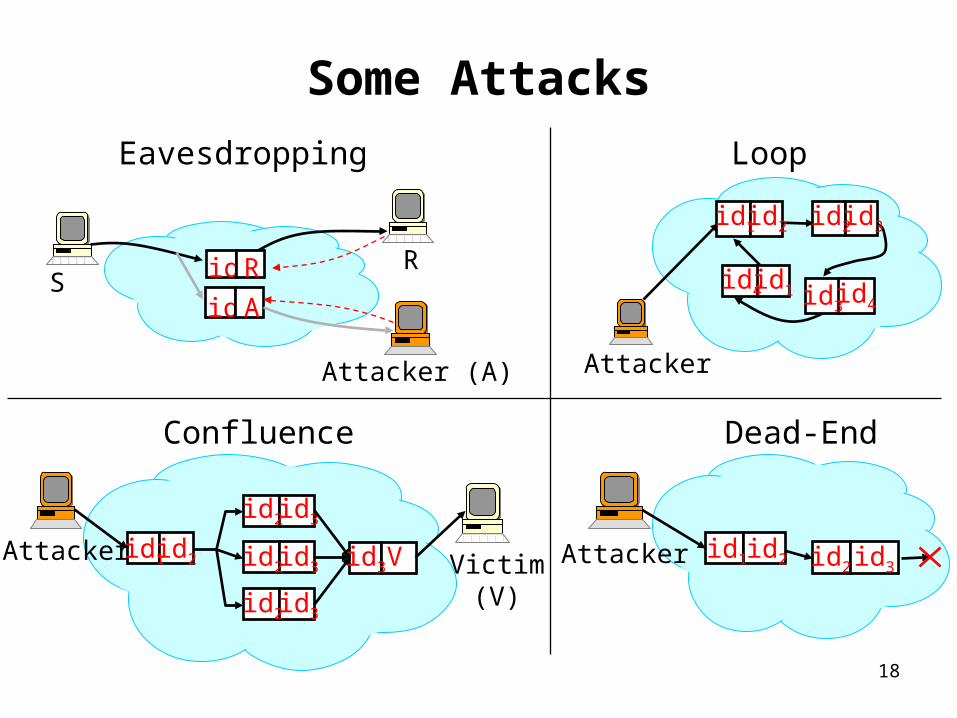
Some Attacks
SRid R
Attacker (A)
id A
Eavesdropping
Attacker
id2 id3id1 id2
id4id3
id1id4
Loop
Victim(V)
id3
id3
id3
V Attacker id2 id2
id2
id2
id1 id3
Confluence
Attacker id2id1 id3id2
Dead-End
19
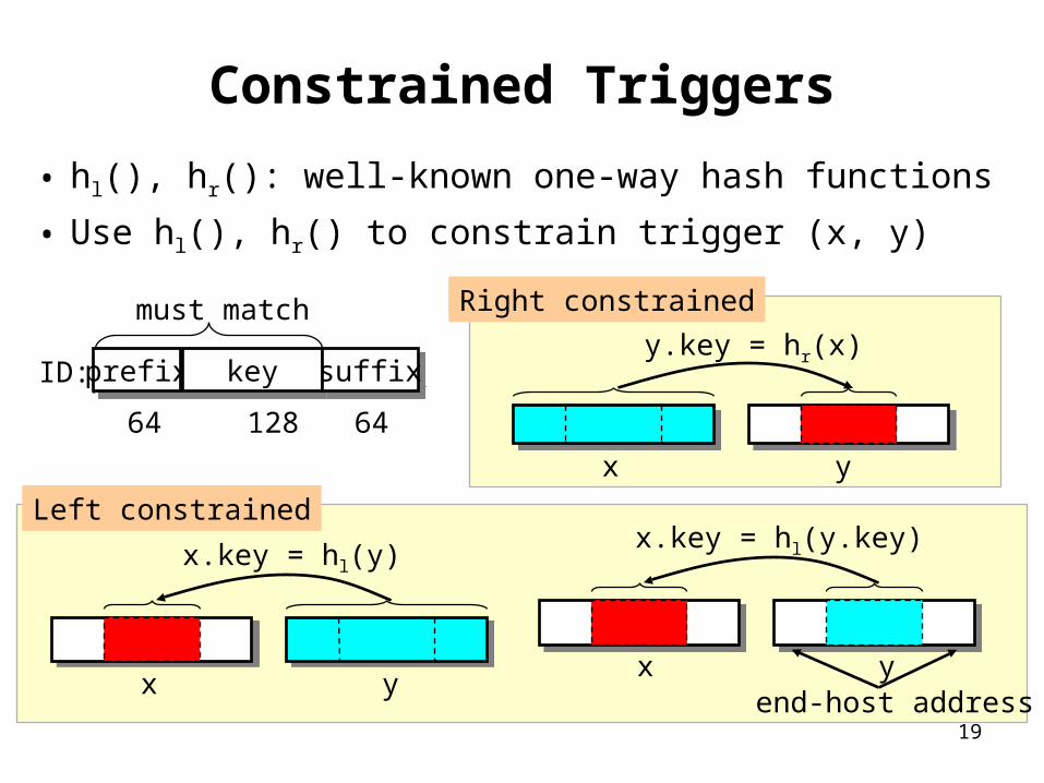
Constrained Triggers
• hl(), hr(): well-known one-way hash functions
• Use hl(), hr() to constrain trigger (x, y)
prefixprefix keykey
64 128 64
must match
ID: suffixsuffix
x y
x.key = hl(y)
x y
x.key = hl(y.key)
end-host address
Left constrained
x y
y.key = hr(x)
Right constrained
20
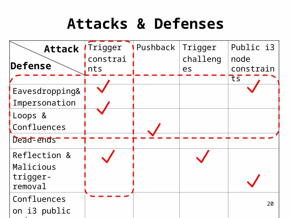
Attacks & Defenses
Triggerconstraints
Pushback Triggerchallenges
Public i3node constraints
Eavesdropping&Impersonation
Loops &Confluences
Dead-ends
Reflection &Malicious trigger-removal
Confluenceson i3 public nodes
Attack
Defense
21
Outline
• Overview• Security Discussion

22
Design Principles
1) Give hosts control on routing– A trigger is like an entry in a routing table!– Flexibility, customization– End-hosts can
• Source route• Set-up acyclic communication graphs • Route packets through desired service points• Stop flows in infrastructure• …
2) Implement data forwarding in infrastructure– Efficiency, scalability
23
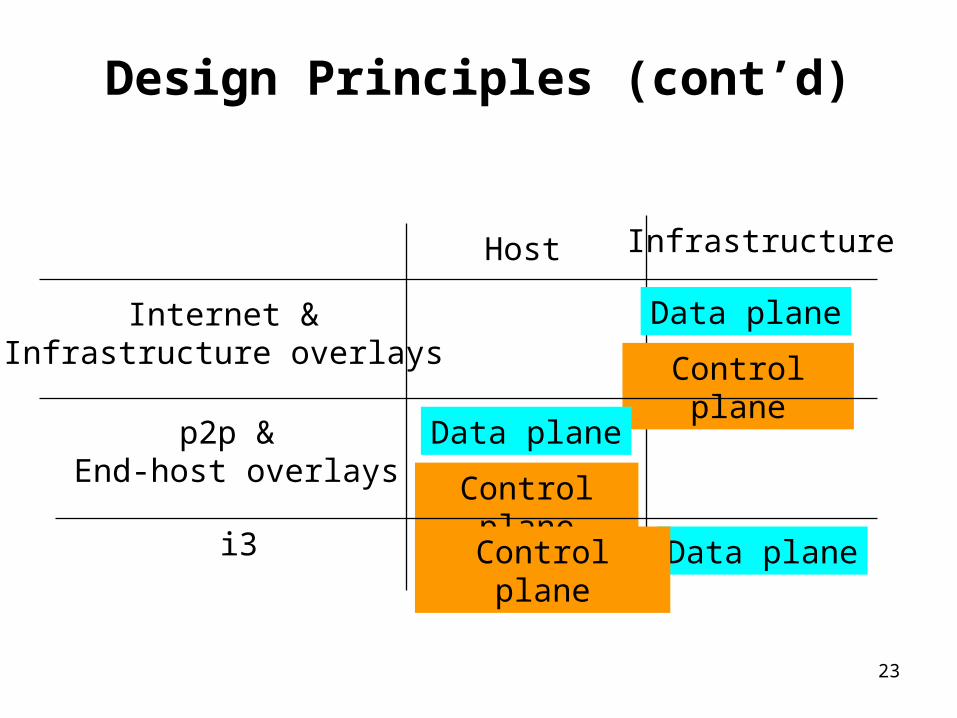
Design Principles (cont’d)
Host Infrastructure
Internet &Infrastructure overlays
Data plane
Control plane
p2p & End-host overlays
Data plane
Control planei3 Data planeControl plane

24
Example: Application Specific Routing
Route Service(ROSE-1)
A
DB
Network measurements
Query/reply routing info.Setup routes
C
ROSE-2

25
Conclusions
• Indirection – key technique to implement basic communication abstractions– Multicast, Anycast, Mobility, …
• This research – Advocates for building an efficient Indirection
Layer on top of IP – Explore the implications of changing the
communication abstraction; already done in other fields
• Direct addressable vs. associative memories• Point-to-point communication vs. Tuple space (in
Distributed systems)