Internet Connectivity Options - BME-HITjakab/edu/litr/VPN/MPLS_VPN_CiscoWP.pdf · to purchase MPLS...
24
Cisco Systems, Inc. All contents are Copyright © 1992–2002 Cisco Systems, Inc. All rights reserved. Important Notices and Privacy Statement. Page 1 of 24 White Paper Internet Connectivity Options Introduction Internet access is perhaps one of the most popular services that Service Providers offer their customers. Customers have flexibility to purchase MPLS VPN services Internet connectivity from separate Service Providers. Customers can alternatively offer Internet connectivity directly from their network may it be from one of their remote sites or the central site. In the latter case, the Internet Service Provider (ISP) does not need to distinguish customer’s Internet and VPN traffic, because all traffic traversing through a Service Provider network would be MPLS VPN traffic. Customers who do not purchase Internet connectivity from a Service Provider do need to work out additional variables: • Routing • Appropriate location for Internet access within the network • Network Implementation Translation (NAT) implementation, if the network does not use public addresses • Security • Additional management and monitoring The best way to offload these responsibilities is to purchase services from a Service Provider. ISPs, Service Providers, and customers often wonder about the best and most highly recommended way to set up Internet connectivity. This varies widely, depending on the topology, requirements, and available resources. This paper will illustrate the advantages and disadvantages of several methods, while recommending a method for the most popular network topology. This document offers a high-level analysis of the methods used to secure networks. For further analysis of MPLS security, please refer to the draft in progress by Michael Behringer: http://www.ietf.org/internet-drafts/ draft-behringer-mpls-security-03.txt There are various possible combinations for using a network infrastructure to implement Internet connectivity, depending on how a Service Provider carries MPLS VPN and Internet traffic. The options at the infrastructure level are: 1. Shared MPLS VPN and Internet Connectivity 2. Partially Shared 3. Full Separation Customers of a Service Provider can always choose to use either multiservice or dedicated CEs, regardless of the infrastructure that the Service Provider has implemented. In addition, Hub/Spoke or fully meshed configuration for customers sites can also be implemented over any aforementioned infrastructure.
Transcript of Internet Connectivity Options - BME-HITjakab/edu/litr/VPN/MPLS_VPN_CiscoWP.pdf · to purchase MPLS...

Cisco Systems, Inc.All contents are Copyright © 1992–2002 Cisco Systems, Inc. All rights reserved. Important Notices and Privacy Statement.
Page 1 of 24
White Paper
Internet Connectivity Options
Introduction
Internet access is perhaps one of the most
popular services that Service Providers offer
their customers. Customers have flexibility
to purchase MPLS VPN services Internet
connectivity from separate Service
Providers. Customers can alternatively
offer Internet connectivity directly from
their network may it be from one of their
remote sites or the central site. In the latter
case, the Internet Service Provider (ISP)
does not need to distinguish customer’s
Internet and VPN traffic, because all traffic
traversing through a Service Provider
network would be MPLS VPN traffic.
Customers who do not purchase Internet
connectivity from a Service Provider do
need to work out additional variables:
• Routing
• Appropriate location for Internet access
within the network
• Network Implementation Translation
(NAT) implementation, if the network
does not use public addresses
• Security
• Additional management and
monitoring
The best way to offload these
responsibilities is to purchase services from
a Service Provider.
ISPs, Service Providers, and customers often
wonder about the best and most highly
recommended way to set up Internet
connectivity. This varies widely, depending
on the topology, requirements, and
available resources. This paper will
illustrate the advantages and disadvantages
of several methods, while recommending a
method for the most popular network
topology.
This document offers a high-level analysis
of the methods used to secure networks. For
further analysis of MPLS security, please
refer to the draft in progress by Michael
Behringer:
http://www.ietf.org/internet-drafts/
draft-behringer-mpls-security-03.txt
There are various possible combinations
for using a network infrastructure to
implement Internet connectivity, depending
on how a Service Provider carries MPLS
VPN and Internet traffic. The options at the
infrastructure level are:
1. Shared MPLS VPN and Internet
Connectivity
2. Partially Shared
3. Full Separation
Customers of a Service Provider can always
choose to use either multiservice or
dedicated CEs, regardless of the
infrastructure that the Service Provider has
implemented. In addition, Hub/Spoke or
fully meshed configuration for customers
sites can also be implemented over any
aforementioned infrastructure.

Cisco Systems, Inc.All contents are Copyright © 1992–2002 Cisco Systems, Inc. All rights reserved. Important Notices and Privacy Statement.
Page 2 of 24
Let’s take a look at the semantics of each of these options and various connectivity implementation options for each
one.
Shared MPLS VPN and Internet Connectivity
Figure 1 shows that both P routers and PE routers support Internet and VPN traffic. A single PE router may connect
both Internet and VPN customers.
Figure 1. Shared MPLS VPN and Internet Connectivity
• PE routers may or may not have a full Internet routing table
• PEs and Internet GW in the same iBGP area
• Share IGP and EGP
• MP-iBGP among PEs as appropriate
Advantages
• One backbone, one network
• Single edge router
• Easier management
• Can offer centralized services
• Single PEs to manage
Disadvantages
• Security (both EGP in the same DB)
• Performance (memory/CPU)
CE InternetMultiservice
PE
DefaultRoute
MultiservicePE
MultiservicePE
Internet GW
Shared BackboneFW
FW
CE
VPNLink
CE VPN
CE CE
Site with Dual Access
Site with Dual Access
Internet Access Only
CE
Site with IntegratedVPN/Internet Access
VPN Access Only
VPNRoutes
DefaultRoute
VPNRoutes
Multiservice PE
Cisco Systems, Inc.All contents are Copyright © 1992–2002 Cisco Systems, Inc. All rights reserved. Important Notices and Privacy Statement.
Page 3 of 24
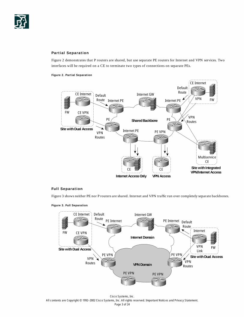
Partial Separation
Figure 2 demonstrates that P routers are shared, but use separate PE routers for Internet and VPN services. Two
interfaces will be required on a CE to terminate two types of connections on separate PEs.
Figure 2. Partial Separation
Full Separation
Figure 3 shows neither PE nor P routers are shared. Internet and VPN traffic run over completely separate backbones.
Figure 3. Full Separation
CE Internet
Internet PE
PE
Internet PE PE VPN
PE
Internet PE
Internet GW
Shared Backbone
FW
FW
CE Internet
VPN
CE VPN
CE CE
Site with Dual Access
Internet Access Only
MultiserviceCE
Site with IntegratedVPN/Internet Access
VPN Access
DefaultRoute
VPNRoutes
DefaultRoute
VPNRoutes
CE Internet
PE Internet
PE VPN
DefaultRoute
PE VPN PE VPN
PE VPN
PE Internet
Internet GW
Internet Domain
VPN Domain
FW
FW
Internet
VPNLink
CE VPN
Site with Dual Access
Site with Dual AccessVPNRoutes VPN
Routes
DefaultRoute

Cisco Systems, Inc.All contents are Copyright © 1992–2002 Cisco Systems, Inc. All rights reserved. Important Notices and Privacy Statement.
Page 4 of 24
Advantages
• Physical separation between Intranet/Extranet and Internet
• Separate IGP and EGP
Disadvantages
• Need to maintain two separate networks
• May not be an economical solution
Over the infrastructures mentioned above, Internet connectivity can be obtained via:
1. Customer Managed Internet Access
2. Simple Solution
3. Sub-interfaces
4. Firewall
5. Multiple ISPs
6. per VRF NAT with a separate Internet Gateway
7. VRFLite(MultiVRF) CE
These represent a high level implementation. Several additional components need to be selected for each option, as
they play an important role. Routing, firewall, and address translation are each key components. These could be in
an overlapping or single VPN environment.
Routing
Location of Internet routing table.
Address Translation
Most ISPs need to solve the issue of address translation deployment, because most customers combine public and
private addresses. NAT could be deployed at CPE side, per VRF at centralized PE that connects to the Internet
gateway (NAT-PE), or any other PE in the path previous to the NAT-PE.
Firewall
Security is the single most important concern for customers when they connect to public networks; therefore, firewall
deployment is a necessity. An appropriate location should be selected for a firewall to block unauthorized traffic into
a customer’s private network. There are several criteria to select when deploying a firewall:
• Managed vs. unmanaged by an ISP
• Shared vs. dedicated per-customer sites
• Network- vs. router-based
– Network-based: appliance (ie: Cisco PIX)
– Router-based: Cisco IOS Software
Several permutations are possible based on these criteria:
1. No NAT, no firewall
2. NAT, but no firewall

Cisco Systems, Inc.All contents are Copyright © 1992–2002 Cisco Systems, Inc. All rights reserved. Important Notices and Privacy Statement.
Page 5 of 24
3. Firewall, but no NAT
4. NAT and firewall
This list could continue if combined with various locations for deployment. This document will briefly cover a few
popular scenarios and later focus on the most practical one in detail.
Customer Managed Internet Access
This scenario has existed since the advent of the Internet. Customers manage their firewall, NAT, and routing for
Internet connectivity. Customers can have one or more gateways to the Internet, depending on their infrastructure
(Centralized or Distributed). This approach gives customers complete control of the network.
Simple Solution
As the name implies, this is the simplest setup. It is also known as Static Default Routing on a PE.
When a customer uses global address space, NAT is not required. If a customer uses private address space, NAT could
be deployed at a CPE, on a PE that is directly connected to VPN CPE, or on a PE that acts as a gateway to the Internet
within an ISP network.
CPE does not need to receive full Internet routing in the simple solution. For CPE-PE, routing is handled on the PE
that is directly connected to a VPN-CPE for distributing routes within a VPN. Between PE and CPE, static route,
RIPv2, OSPF or eBGP can be used to update routing information. No additional configuration is required on a CPE,
provided that it has a default static route to the PE to reach the Internet.
Figure 4. Simple Solution
Service ProviderCisco MPLS—VPN Network
VPN-A
Internet
VPN-B
VPN-A
VPN-A
VPN-B
VPN-B
VPN-A
CE
CE
VPN-B
CE
CE
CE
CE
CE
CE
PE1
PE2
Internet GW
Internet RoutingTable
PE3
PE4
Cisco Systems, Inc.All contents are Copyright © 1992–2002 Cisco Systems, Inc. All rights reserved. Important Notices and Privacy Statement.
Page 6 of 24
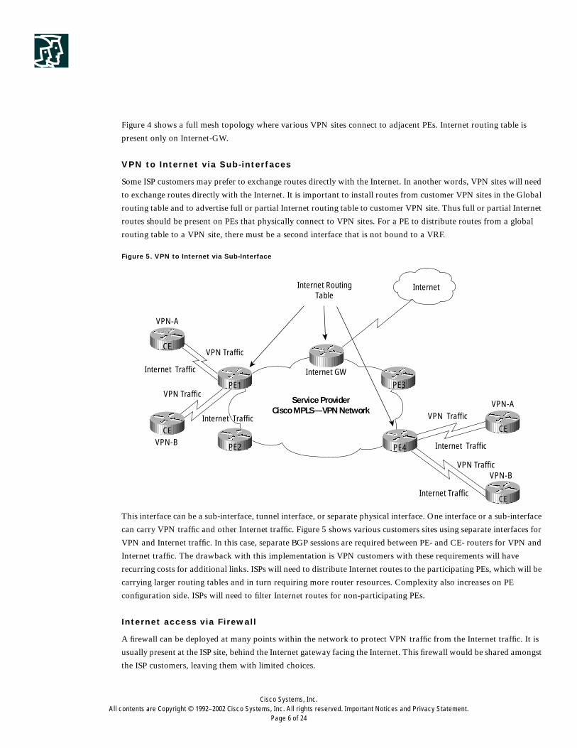
Figure 4 shows a full mesh topology where various VPN sites connect to adjacent PEs. Internet routing table is
present only on Internet-GW.
VPN to Internet via Sub-interfaces
Some ISP customers may prefer to exchange routes directly with the Internet. In another words, VPN sites will need
to exchange routes directly with the Internet. It is important to install routes from customer VPN sites in the Global
routing table and to advertise full or partial Internet routing table to customer VPN site. Thus full or partial Internet
routes should be present on PEs that physically connect to VPN sites. For a PE to distribute routes from a global
routing table to a VPN site, there must be a second interface that is not bound to a VRF.
Figure 5. VPN to Internet via Sub-Interface
This interface can be a sub-interface, tunnel interface, or separate physical interface. One interface or a sub-interface
can carry VPN traffic and other Internet traffic. Figure 5 shows various customers sites using separate interfaces for
VPN and Internet traffic. In this case, separate BGP sessions are required between PE- and CE- routers for VPN and
Internet traffic. The drawback with this implementation is VPN customers with these requirements will have
recurring costs for additional links. ISPs will need to distribute Internet routes to the participating PEs, which will be
carrying larger routing tables and in turn requiring more router resources. Complexity also increases on PE
configuration side. ISPs will need to filter Internet routes for non-participating PEs.
Internet access via Firewall
A firewall can be deployed at many points within the network to protect VPN traffic from the Internet traffic. It is
usually present at the ISP site, behind the Internet gateway facing the Internet. This firewall would be shared amongst
the ISP customers, leaving them with limited choices.
Service ProviderCisco MPLS—VPN Network
VPN-A
VPN Traffic
VPN Traffic
VPN Traffic
VPN Traffic
Internet Traffic
Internet Traffic
Internet Traffic
Internet Traffic
Internet
VPN-A
VPN-B
VPN-BCE
CE
CE
CE
PE1
PE2
Internet GW
Internet RoutingTable
PE3
PE4

Cisco Systems, Inc.All contents are Copyright © 1992–2002 Cisco Systems, Inc. All rights reserved. Important Notices and Privacy Statement.
Page 7 of 24
If a VPN topology were fully meshed, then deploying a firewall at every site facing the ISP network could be one
solution. If a customer topology followed the central site (hub/spoke) model, then deploying a firewall at the Hub
site would be sufficient. In the latter case, VPN sites would import a default route to the central site CE, which is
generated and updated by the central site CE.
Figure 6 shows a hub/spoke topology where a Cisco IOS firewall is deployed on a. CE router at a hub site.
Figure 6. Internet Access via Firewall
Notice, Internet traffic from any Spoke VPN sites need to pass through a firewall. Since the central site is providing
firewall services (as shown in figure 6), a static default route pointing to the central site firewall should be installed
in associated FIB tables for each spoke sites.
Multiple ISPs
Some customers may choose to obtain Internet Connectivity via different Service Providers. Several combinations are
possible depending on whether the customer network uses full mesh or hub and spoke model. In either case, exit
points in the network needs to be planned out so that traffic load is well distributed. Exit point will be selected based
on the best path determined by a routing protocol.
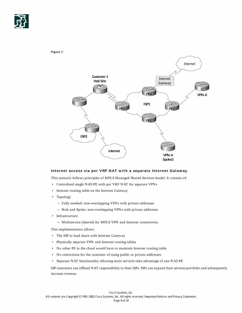
Figure 7 shows an example where Customer1 has Internet connectivity and MPLS/VPN services from ISP1. MPLS/
VPN and Internet traffic is routed over separate interfaces. There is another exit point for Internet traffic at the hub
site which is routed via Service Provider ISP2 network.
Service ProviderCisco MPLS—VPN Network
VPN-ACentral Site Hub Internet
Gateway
Internet
VPN-BCentral Site Hub
VPN-ASpoke
VPN-ASpoke
VPN-BSpoke
VPN-BSpoke
VPN-ASpoke
CE
CE
CE
CE
CE
PE1
PE2
PE5
PE3
PE4
Cisco Systems, Inc.All contents are Copyright © 1992–2002 Cisco Systems, Inc. All rights reserved. Important Notices and Privacy Statement.
Page 8 of 24
Figure 7.
Internet access via per VRF NAT with a separate Internet Gateway
This scenario follows principles of MPLS Managed Shared Services model. It consists of:
• Centralized single NAT-PE with per VRF NAT for separate VPNs
• Internet routing table on the Internet Gateway
• Topology
– Fully meshed: non-overlapping VPNs with private addresses
– Hub and Spoke: non-overlapping VPNs with private addresses
• Infrastructure
– Multiservice (shared) for MPLS VPN and Internet connectivity
This implementation allows:
• The ISP to load share with Internet Gateway
• Physically separate VPN and Internet routing tables
• No other PE in the cloud would have to maintain Internet routing table
• No restrictions for the customer of using public or private addresses
• Separate NAT functionality allowing more services take advantage of one NAT-PE
ISP customers can offload NAT responsibility to their ISPs. ISPs can expand their services portfolio and subsequently
increase revenue.
ISP2
InternetVPN-ASpoke2
VPN-A
ISP1PE1 PE3
CPE4
PE2
Customer 1Hub Site
InternetGateway
Internet

Cisco Systems, Inc.All contents are Copyright © 1992–2002 Cisco Systems, Inc. All rights reserved. Important Notices and Privacy Statement.
Page 9 of 24
Case A: with Fully Meshed Topology
Figure 8 shows part of a typical Service Provider network. Several geographically dispersed customer sites are part
of VPN-A and VPN-B. Some of these sites connect directly to the NAT-PE where address translation takes place.
Others connect via various PEs. The interface directly connecting to the Internet Gateway will be the outside
interface.
The interfaces connecting to other PEs or adjacent VPN sites will be inside interfaces.
Figure 8. Per VRF NAT with fully meshed VPN sites
CE-PE
Use static default route for VPN and Internet traffic to directly connected PE.
PE
The PE does not carry any Internet routes. They only carry routes for appropriate VPN sites and the backbone.
VPN-A
VPN-A
VPN-A VPN-A
VPN-B
VPN-B
VPN-B
VPN-B
10.1.4x/24
10.1.1x/24
10.1.2x/24 10.1.5x/24
10.1.3x/24
CE4A
NAT-PE
Service ProviderCisco MPLS—VPN Network
CE4B
CE1A
VPN-A
CE3A
CE1BVPN-B
CE3B
CE2A
CE2B
CE5A
CE5B
PE1
PE2
PE3
PE5
InternetGateway
Internet

Cisco Systems, Inc.All contents are Copyright © 1992–2002 Cisco Systems, Inc. All rights reserved. Important Notices and Privacy Statement.
Page 10 of 24
A default static route is applied to participating PEs FIB tables that are associated with customers’ VRFs, which need
to support Internet connectivity service. The next-hop address used in the static route is an address of the interface
from which the Internet routes are learned, rather than an address of the loopback interface on the Internet Gateway.
This will eliminate sub-optimal routing and the possibility of black-holing traffic designated for the Internet. The
route to this interface would be known via IGP.
The other option is to use the next-hop address of the NAT-PE. The NAT-PE would neighbor with the Internet
Gateway, so it can get updates on addresses used on the Internet Gateway. This will avoid the distribution of any
subnets of Internet Gateway to the PEs. The drawback to this option is similar to that of using the next-hop address
of a loopback interface. Alternatively, this should not be a concern if the back-up interfaces are used on the Internet
Gateway.
Additionally, the next-hop of the default static route will be present in the global routing table, but not in the VRF
table. Since there is no redistribution between IPv4 and VPN-IPv4 routes, additional technique is required to resolve
the next-hop address for the Internet Gateway from within a VRF. This is achieved by using ‘global’ keyword within
the static default route configuration on an appropriate PE.
All the traffic is forwarded with the appropriate VPN label attached. The need for this is dictated by overlapping
private IP addresses that have not been translated to unique public IP addresses. When NAT-PE receives these
packets, it needs to recognize the associated VPN, so it can select appropriate pools for translation.
NAT-PE
NAT occurs on the NAT-PE for all customers that use private addresses and need Internet connectivity. In this
scenario, the ISP has only one Internet Gateway that is directly connected to the NAT-PE.
Since the translation occurs on a dedicated NAT-PE, translated public addresses could be updated by means of
routing protocol to the neighbor Internet Gateway, via IGP to forward the returned traffic from the internet to
appropriate VPNs. Internet Gateway will forward the response traffic back to the NAT-PE. NAT-PE will translate
addresses back to the original private IP addresses, and then forward the traffic to the appropriate VPNs.
The other option is to follow the distributed model and deploy per VRF NAT on PEs where VRFs are present. This
would complicate configuration and make management of IP address pools awkward.
Note: there are no MP-iBGP sessions set up between the PEs and the Internet Gateway. The Internet Gateway does
not have any knowledge of VPNs. It receives packets as IPv4 packets from the NAT-PE, and forwards the return
traffic to the NAT-PE. Upon receiving the packets, NAT translation occurs again on outside to inside path.
• The Internet services interfaces should be configured as NAT outside on the NAT-PE.
• The VRF interfaces and core facing MPLS-enabled interface should be configured as NAT inside on the NAT-PE.
• The interface connecting to the Internet Gateway is a non-VRF interface.
Inside to Outside packet flow on the NAT-PE:
Translations will take place on the NAT-PE interface that is physically connected to the Internet Gateway.
As a packet arrives on the NAT-PE destined for the Internet:
• Route lookup occurs
• NAT receives the packet
• NAT translates the packet

Cisco Systems, Inc.All contents are Copyright © 1992–2002 Cisco Systems, Inc. All rights reserved. Important Notices and Privacy Statement.
Page 11 of 24
• Stores the VRF table ID in the translation entry
• Packet is switched to the egress interface
Outside to Inside packet flow on the NAT-PE:
NAT receives the packet before routing and performs lookup on the translation table. NAT performs the reverse
translation, and also sets the VRF table ID in the packet descriptor header. This enables the subsequent route lookup
to occur on the right Forwarding Information Block (FIB). If the outgoing interface is in a VRF on the same PE, then
the packet is forwarded as an IP packet. If the destination is on a remote PE, then the packet is imposed with labels
and forwarded on the core facing interface.
Internet Gateway
The Internet Gateway holds full Internet routes, translated networks, and appropriate backbone routes. It forwards
IP packets to and from the NAT-PE to the Internet.
Configuration Check List
In addition to the basic IGP, VRF, and MP-iBGP configuration:
1. Static default route with ‘global’ keyword option on a participating PE pointing to the next-hop address of the
Internet Gateway.
2. NAT on a NAT-PE for every VRF. Could use same or dedicated pool per VRF.
– Dedicated pools are used in this example.
3. Static route pointing to each VRFs on a NAT-PE.
VPN-A and VPN-B use overlapping private address space.
NAT-PE Sample Configuration
hostname NAT-PE!ip nat pool pool1 171.1.1.2 171.1.254.254 mask 255.255.0.0ip nat pool pool2 171.2.1.2 171.2.254.254 mask 255.255.0.0!ip nat inside source list 1 pool pool1 vrf VPN-Aip nat inside source list 1 pool pool2 vrf VPN-B!ip route vrf VPN-A 171.1.0.0 0.0.255.255 ge1/0ip route vrf VPN-B 171.2.0.0 0.0.255.255 ge1/0!(ge1/0 is the Gigbit Ethernet interface on Internet Gateway which is directly!connected to the NAT-PE).
Interface ge1/0description interface directly connected to the Internet Gatewayip nat outside!Interface ge1/1description interface to another PEip nat inside!access-list 1 permit 10.1.0.0 0.0.255.255
Notice, no NAT configuration required on any other CEs or PEs. Configure PEs for appropriate MP-iBGP sessions
with NAT-PE and other PEs where additional sites belonging to the same VPNs are located.

Cisco Systems, Inc.All contents are Copyright © 1992–2002 Cisco Systems, Inc. All rights reserved. Important Notices and Privacy Statement.
Page 12 of 24
CASE B: with Hub & Spoke Topology
Figure 9. Hub and Spoke Topology
Note: in this topology (Figure 9), CE1A and CE1B are Hub sites, while the rest are spoke sites. The requirement
is that all spoke traffic must be forwarded via Hub site to the appropriate destination. The only difference here is that
on PE2, PE3, NAT-PE and PE5, the next hop in the default static route will be that of CE1A’s interface for the sites
in VPN-A and CE1B’s for the sites in VPN-B. The next hop address used on PE1 will be that of the interface facing
the Internet on the Internet Gateway.
The rest of the process for forwarding/receiving the Internet traffic to and from the NAT-PE from PE1 will be the
same as described in Case A. The only difference is that a Service Provider must ensure that PE1 (PE serving the Hub
site) can support the traffic load.
VRFLite(MultiVRF) CE
If VRF Lite is deployed at a customer site, Internet connectivity still can be offered by combining #1 with VRF Lite.
Overlapping address space is supported in VRF Lite, because routing-forwarding tables are kept separate on a VRF
CE for each VPN. If address translation is required, it can be performed using a NAT-PE (see Case #6).
VPN-ASpoke
Spoke
Spoke Spoke
Spoke
Spoke
Spoke
Spoke
HUB
HUB
VPN-A
VPN-A VPN-A
VPN-B
VPN-B
VPN-B
VPN-B
10.1.4x/24
10.1.1x/24
10.1.1x/24
10.1.2x/24
10.1.2x/24
10.1.5x/24
10.1.3x/24
10.1.3x/24
CE4A
NAT-PE
Service ProviderCisco MPLS—VPN Network
CE4B
CE1A
VPN-A
CE3A
CE1BVPN-B
CE3B
CE2A
CE2B
CE5A
CE5B
PE1
PE2
PE3
PE5
InternetGateway
Internet

Cisco Systems, Inc.All contents are Copyright © 1992–2002 Cisco Systems, Inc. All rights reserved. Important Notices and Privacy Statement.
Page 13 of 24
The following example demonstrates a Service Provider offering Internet connectivity over VRF Lite:
• There are 2 PE routers in the network and one CE, 2611 configured for VRF-lite
• In this case study, all sub-interfaces off the 2621-CE6 can communicate with VXR-CE, but not with each
other.2611-CE5 can communicate with VXR-CE, but not with any host off 2621-CE6All traffic off 2611-CE-4
is segmented into 5 separate VRFs (labeled vrflite1-5)
• These two connections use OSPF as the routing protocol to exchange updates with 2611-CE4, (but other routing
protocols may be used as well).
• All other hosts off 2611-CE4 use a combination of OSPF, EBGP, RIPv2 and static routes.
Topology
Figure 10. VRF Lite
Separate FIB tables are maintained on 2611-CE-4 for each VRFs. Figure 11, shows detailed connectivity information
between 3640-PE1 and 2611-CE-4(VRF Lite CE). Notice, there is no separate sub-interface for Internet traffic.
VXR-CEVRF V15
10.15.44.4
10.13.1.483640-PE2
3640-PE110.13.1.65
NAT-PE
InternetGW
10.13.1.61
10.1.65.x
10.13.1.742611-CE-4VRF Lite
VRF Lite1
VRF Lite2
2621-CE-6-e0/1.1110.10.1x
2621-CE-6-e0/1.1210.10.2x
VRF Lite32621-CE-6-e0/1.1310.10.3x
VRF Lite4
2621-CE-6-e0/1.1410.10.43x
VRF Lite5
2621-CE-5
MPLS Core
Internet

Cisco Systems, Inc.All contents are Copyright © 1992–2002 Cisco Systems, Inc. All rights reserved. Important Notices and Privacy Statement.
Page 14 of 24
Internet and VPN traffic from each VRFLite sites(VRFLite1, VRFLite2…etc.), will be sent on their associated
sub-interfaces from 2611-CE-4 to 3640-PE1. Default static route for the Internet, is present in each FIB table on
2611-CE-4 and 3640-PE1. Thus returning Internet traffic for each of the VRF Lite Site, will go over the associated
sub-interface from 3640-PE1 to 2611-CE-4. Appropriate FIB tables will be consulted on 2611-CE-4 before
forwarding the traffic to remote VRFLite sites (ie: VRFLite1, VRFLite2.).
Figure11. VRF Lite CE-PE
Mappings between VRFs on 2640-PE1 and 2611-CE-4:
Configurations for Some CE and PE Routers
3640-PE13640-PE-WEST-1#sh runhostname 3640-PE-WEST-1ip subnet-zero!ip vrf v11 rd 11:1 route-target export 11:1 route-target import 11:1!ip vrf v12 rd 12:1 route-target export 12:1 route-target import 12:1!ip vrf v13 rd 13:1 route-target export 13:1 route-target import 13:1!ip vrf v14 rd 14:1 route-target export 14:1
3640-PE1 VRFs 2611-CE-4 VRFs
v11 vrflite1
v12 vrflite2
v13 vrflite3
v14 vrflite4
v15 vrflite5
VRF v11int s2/0:0.1, 10.1.65.5
3640-PE1
VRF v12int s2/0:0.2, 10.1.65.9
VRF vrflite1int s0/0.1, 10.1.65.6
VRF vrflite2int s0/0.1, 10.1.65.10
Internet & VPN traffic fromVRFLite2 site: 10.10.1.x
Internet & VPN traffic fromVRFLite2 site: 10.10.2.x

Cisco Systems, Inc.All contents are Copyright © 1992–2002 Cisco Systems, Inc. All rights reserved. Important Notices and Privacy Statement.
Page 15 of 24
route-target import 14:1!ip vrf v15 rd 15:1 route-target export 15:1 route-target import 15:1!ip cef!controller T1 2/0 framing esf linecode b8zs channel-group 0 timeslots 1-24!interface Loopback0
description Router ID ip address 10.13.1.65 255.255.255.255!interface FastEthernet1/0
description FE to GSR-P-CENTRAL-A - 4.16 ip address 10.13.4.18 255.255.255.252 duplex auto speed auto!interface Serial2/0:0
description T1 connection to CE - VRF_Lite no ip address encapsulation frame-relay!interface Serial2/0:0.1 point-to-point
description PE to VRF_Lite CE connection 1 ip vrf forwarding v11 ip address 10.1.65.5 255.255.255.252 frame-relay interface-dlci 21!interface Serial2/0:0.2 point-to-point
description PE to VRF_Lite CE connection 2 ip vrf forwarding v12 ip address 10.1.65.9 255.255.255.252 frame-relay interface-dlci 22!interface Serial2/0:0.3 point-to-point
description PE to VRF_Lite CE connection 3 ip vrf forwarding v13 ip address 10.1.65.13 255.255.255.252 frame-relay interface-dlci 23!interface Serial2/0:0.4 point-to-point
description PE to VRF_Lite CE connection 4 ip vrf forwarding v14 ip address 10.1.65.17 255.255.255.252 frame-relay interface-dlci 24!interface Serial2/0:0.5 point-to-point
description PE to VRF_Lite CE connection 5 ip vrf forwarding v15 ip address 10.1.65.21 255.255.255.252

Cisco Systems, Inc.All contents are Copyright © 1992–2002 Cisco Systems, Inc. All rights reserved. Important Notices and Privacy Statement.
Page 16 of 24
frame-relay interface-dlci 25!router ospf 15 vrf v15 log-adjacency-changes area 15 virtual-link 220.1.65.22 redistribute bgp 1 subnets network 10.1.65.20 0.0.0.3 area 15!router ospf 11 vrf v11 log-adjacency-changes area 11 virtual-link 220.1.65.6 redistribute bgp 1 subnets network 10.1.65.4 0.0.0.3 area 11!router ospf 12 vrf v12 log-adjacency-changes redistribute bgp 1 subnets network 10.1.65.8 0.0.0.3 area 12!router ospf 13 vrf v13 log-adjacency-changes redistribute bgp 1 subnets network 10.1.65.12 0.0.0.3 area 13!router ospf 14 vrf v14 log-adjacency-changes redistribute bgp 1 subnets network 10.1.65.16 0.0.0.3 area 14!router ospf 1 log-adjacency-changes network 10.13.1.65 0.0.0.0 area 6 network 10.13.4.16 0.0.0.3 area 6!router bgp 1 no synchronization no bgp default ipv4-unicast bgp log-neighbor-changes neighbor 10.13.1.48 remote-as 1 neighbor 10.13.1.48 update-source Loopback0 neighbor 10.13.1.48 activate neighbor 10.13.1.61 remote-as 1 neighbor 10.13.1.61 update-source Loopback0 neighbor 10.13.1.61 activate no auto-summary ! address-family ipv4 vrf v15 redistribute ospf 15 default-metric 10 no auto-summary no synchronization exit-address-family ! address-family ipv4 vrf v14 redistribute ospf 14 match internal external 1 external 2 default-metric 10 no auto-summary

Cisco Systems, Inc.All contents are Copyright © 1992–2002 Cisco Systems, Inc. All rights reserved. Important Notices and Privacy Statement.
Page 17 of 24
no synchronization exit-address-family ! address-family ipv4 vrf v13 redistribute ospf 13 match internal external 1 external 2 default-metric 10 no auto-summary no synchronization exit-address-family ! address-family ipv4 vrf v12 redistribute ospf 12 match internal external 1 external 2 default-metric 10 no auto-summary no synchronization exit-address-family ! address-family ipv4 vrf v11 redistribute ospf 11 default-metric 10 no auto-summary no synchronization exit-address-family! address-family vpnv4 neighbor 10.13.1.48 activate neighbor 10.13.1.48 send-community extended neighbor 10.13.1.61 activate neighbor 10.13.1.61 send-community extended no auto-summary exit-address-family!ip classlessno ip http serverntp clock-period 17179973end
2611-CE-42611-CE-4#sh runhostname 2611-CE-4!ip vrf vrflite1 rd 81:81 !ip vrf vrflite2 rd 82:82 !ip vrf vrflite3 rd 83:83 !ip vrf vrflite4 rd 84:84 !ip vrf vrflite5 rd 85:85!ip cef

Cisco Systems, Inc.All contents are Copyright © 1992–2002 Cisco Systems, Inc. All rights reserved. Important Notices and Privacy Statement.
Page 18 of 24
frame-relay switchingcns event-service server!interface Loopback0
description Router ID ip address 10.13.1.74 255.255.255.255!interface Serial0/0
description T1 connection to PE - VRF_Lite no ip address encapsulation frame-relay no fair-queue service-module t1 clock source internal service-module t1 timeslots 1-24 speed 56 frame-relay intf-type dce!interface Serial0/0.1 point-to-point
description VRF_Lite CE to PE connection 1 ip vrf forwarding vrflite1 ip address 10.1.65.6 255.255.255.252 frame-relay interface-dlci 21!interface Serial0/0.2 point-to-point
description VRF_Lite CE to PE connection 2 ip vrf forwarding vrflite2 ip address 10.1.65.10 255.255.255.252 frame-relay interface-dlci 22!interface Serial0/0.3 point-to-point
description VRF_Lite CE to PE connection 3 ip vrf forwarding vrflite3 ip address 10.1.65.14 255.255.255.252 frame-relay interface-dlci 23!interface Serial0/0.4 point-to-point
description VRF_Lite CE to PE connection 4 ip vrf forwarding vrflite4 ip address 10.1.65.18 255.255.255.252 frame-relay interface-dlci 24!interface Serial0/0.5 point-to-point
description VRF_Lite CE to PE connection 5 ip vrf forwarding vrflite5 ip address 10.1.65.22 255.255.255.252 frame-relay interface-dlci 25!interface Ethernet0/1
description Subinterfaces to Host CE no ip address half-duplex!interface Ethernet0/1.11
description VRF_Lite CE to host 1 (dup addr) encapsulation dot1Q 11 ip vrf forwarding vrflite1 ip address 10.10.1.1 255.255.255.0!
Cisco Systems, Inc.All contents are Copyright © 1992–2002 Cisco Systems, Inc. All rights reserved. Important Notices and Privacy Statement.
Page 19 of 24
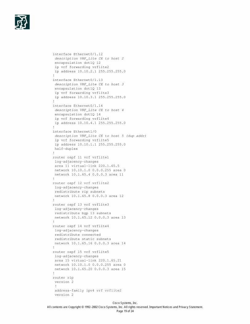
interface Ethernet0/1.12description VRF_Lite CE to host 2
encapsulation dot1Q 12 ip vrf forwarding vrflite2 ip address 10.10.2.1 255.255.255.0!interface Ethernet0/1.13
description VRF_Lite CE to host 3 encapsulation dot1Q 13 ip vrf forwarding vrflite3 ip address 10.10.3.1 255.255.255.0!interface Ethernet0/1.14
description VRF_Lite CE to host 4 encapsulation dot1Q 14 ip vrf forwarding vrflite4 ip address 10.10.4.1 255.255.255.0!interface Ethernet1/0
description VRF_Lite CE to host 5 (dup addr) ip vrf forwarding vrflite5 ip address 10.10.1.1 255.255.255.0 half-duplex!router ospf 11 vrf vrflite1 log-adjacency-changes area 11 virtual-link 220.1.65.5 network 10.10.1.0 0.0.0.255 area 0 network 10.1.65.4 0.0.0.3 area 11!router ospf 12 vrf vrflite2 log-adjacency-changes redistribute rip subnets network 10.1.65.8 0.0.0.3 area 12!router ospf 13 vrf vrflite3 log-adjacency-changes redistribute bgp 13 subnets network 10.1.65.12 0.0.0.3 area 13!router ospf 14 vrf vrflite4 log-adjacency-changes redistribute connected redistribute static subnets network 10.1.65.16 0.0.0.3 area 14!router ospf 15 vrf vrflite5 log-adjacency-changes area 15 virtual-link 220.1.65.21 network 10.10.1.0 0.0.0.255 area 0 network 10.1.65.20 0.0.0.3 area 15!router rip version 2 ! address-family ipv4 vrf vrflite2 version 2
Cisco Systems, Inc.All contents are Copyright © 1992–2002 Cisco Systems, Inc. All rights reserved. Important Notices and Privacy Statement.
Page 20 of 24
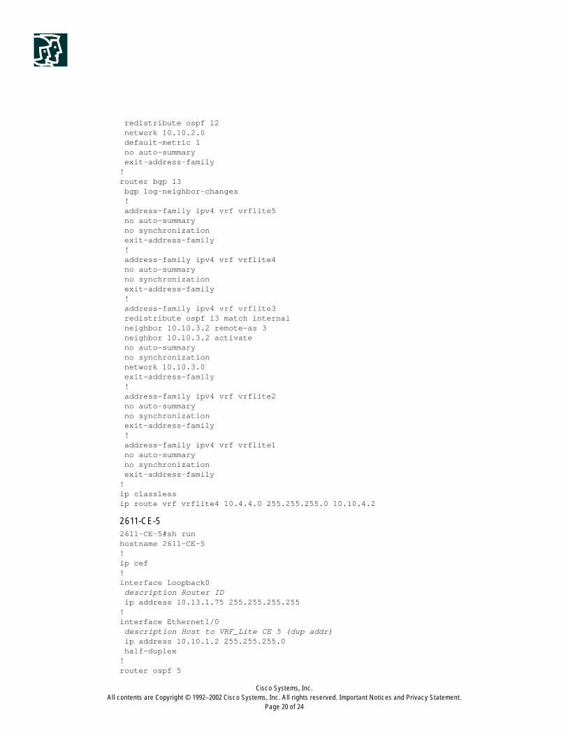
redistribute ospf 12 network 10.10.2.0 default-metric 1 no auto-summary exit-address-family!router bgp 13 bgp log-neighbor-changes ! address-family ipv4 vrf vrflite5 no auto-summary no synchronization exit-address-family ! address-family ipv4 vrf vrflite4 no auto-summary no synchronization exit-address-family ! address-family ipv4 vrf vrflite3 redistribute ospf 13 match internal neighbor 10.10.3.2 remote-as 3 neighbor 10.10.3.2 activate no auto-summary no synchronization network 10.10.3.0 exit-address-family ! address-family ipv4 vrf vrflite2 no auto-summary no synchronization exit-address-family ! address-family ipv4 vrf vrflite1 no auto-summary no synchronization exit-address-family!ip classlessip route vrf vrflite4 10.4.4.0 255.255.255.0 10.10.4.2
2611-CE-52611-CE-5#sh runhostname 2611-CE-5!ip cef!interface Loopback0
description Router ID ip address 10.13.1.75 255.255.255.255!interface Ethernet1/0
description Host to VRF_Lite CE 5 (dup addr) ip address 10.10.1.2 255.255.255.0 half-duplex!router ospf 5
Cisco Systems, Inc.All contents are Copyright © 1992–2002 Cisco Systems, Inc. All rights reserved. Important Notices and Privacy Statement.
Page 21 of 24
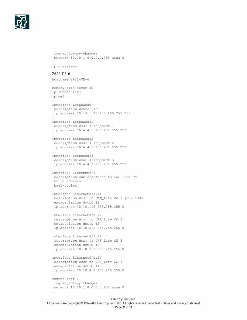
log-adjacency-changes network 10.10.1.0 0.0.0.255 area 0!ip classless
2621-CE-6hostname 2621-CE-6!memory-size iomem 30ip subnet-zeroip cef!interface Loopback0
description Router ID ip address 10.13.1.76 255.255.255.255!interface Loopback41
description Host 4 loopback 1 ip address 10.4.4.1 255.255.255.252!interface Loopback42
description Host 4 loopback 2 ip address 10.4.4.5 255.255.255.252!interface Loopback43
description Host 4 loopback 3 ip address 10.4.4.9 255.255.255.252!interface Ethernet0/1
description Subinterfaces to VRF-Lite CE no ip address half-duplex!interface Ethernet0/1.11
description Host to VRF_Lite CE 1 (dup addr) encapsulation dot1Q 11 ip address 10.10.1.2 255.255.255.0!interface Ethernet0/1.12
description Host to VRF_Lite CE 2 encapsulation dot1Q 12 ip address 10.10.2.2 255.255.255.0!interface Ethernet0/1.13
description Host to VRF_Lite CE 3 encapsulation dot1Q 13 ip address 10.10.3.2 255.255.255.0!interface Ethernet0/1.14
description Host to VRF_Lite CE 4 encapsulation dot1Q 14 ip address 10.10.4.2 255.255.255.0!router ospf 1 log-adjacency-changes network 10.10.1.0 0.0.0.255 area 0!

Cisco Systems, Inc.All contents are Copyright © 1992–2002 Cisco Systems, Inc. All rights reserved. Important Notices and Privacy Statement.
Page 22 of 24
router rip version 2 network 10.10.2.0!router bgp 3 bgp log-neighbor-changes neighbor 10.10.3.1 remote-as 13 neighbor 10.10.3.1 update-source Ethernet0/1.13!ip classlessip route 10.1.65.16 255.255.255.252 10.10.4.1
Closing Remarks
Internet access is the most basic and common requirement for many businesses. By offering additional sets of services
to their customers across VPNs, Service Providers can increase services portfolio, differentiate themselves from their
competition, increase customer satisfaction, and increase revenue.
This document assessed several methods available to provide Internet connectivity; including the advantages and
drawbacks associated with each method.
In any case, Service Providers can select the most appropriate way of providing this service, based on their topology
and customer requirements.
An Enterprise (ISP) customer should consider these factors when selecting Internet access:
1. Multiple ISPs, only getting Internet connectivity: set up Enterprise network to use the best BGP path to the
Internet exit points.
2. Multiple ISPs, getting MPLS VPN and Internet connectivity through one and only Internet connectivity through
other: set up their network to use best BPG path to Internet exit points.
3. Same ISP for MPLS VPN and Internet connectivity:
– Two sub-Interfaces from a CE to the same PE or two sub-interfaces to two separate PEs: default route for the
Internet traffic over one sub-interface. Static or dynamic routes with a PE for MPLS VPN over another
Sub-interface.
– Over one Interface: static route for Internet traffic, dynamic routes for MPLS VPN.
4. Same ISP, but want all INET routes: do eBGP session with ISP’s Internet GW. This could be done with 3a or 3b.
ISPs must consider the following checklist while designing a network to support Internet connectivity service:
1. Shared, full separation, or partial separation (multiservice or not?) at the infrastructure level for VPN traffic and
Internet traffic
2. Overlapping or non-overlapping VPNs
3. VRF or non-VRF interface for Internet access
4. Huband spoke or fully-meshed topology
5. Public versus private addresses
6. Centralized or distributed NAT; single or multiple centralized NAT PEs

Cisco Systems, Inc.All contents are Copyright © 1992–2002 Cisco Systems, Inc. All rights reserved. Important Notices and Privacy Statement.
Page 23 of 24
7. Firewall:
– Managed or unmanaged
– Location
– Type (integrated in Cisco IOS Software or appliance-based)
8. Use of a global routing table or a static route to separate and forward traffic
9. Internet routing table location
– CEs or PEs
– Single or multiple Internet gateways
10. Static or dynamic routing between CEs and PEs
Security Considerations
In a multiservice environment, VPN and Internet traffic share the same wire. It is critical that a Service Provider
implement strong security policies to ensure VPNs are not threatened by Internet traffic.
When possible, use several of the following techniques:
• Multiple layers of filtering
• Anti-spoofing
• SSH
• Intrusion detection
• Multi-virus scanning
• Rate-limiting
• Route filtering within a VPN
• Limiting numbers of routes within a VPN
• Route dampening
• MD5 authentication for routing protocols
• Physical separation of Internet and VPN routes
In any case, the provider should assure invisibility of edge and core to the Internet, as well to the VPN networks.
As specified in RFC2547 (and as discussed in draft-behringer-mpls-security-07.txt) MPLS network guarantees:
• Address space, Routing and Traffic separation
• Invisible SP core
• Resistance to attacks
MPLS network does not address basic security concerns such as securing network elements against:
• Misconfigured Core
• Internal core attacks
• External core attacks
• Attacks to VPNs from the same VPNs
• Unauthorized access
Thus, additional security measurements as mentioned above should be considered.

Corporate HeadquartersCisco Systems, Inc.170 West Tasman DriveSan Jose, CA 95134-1706USAwww.cisco.comTel: 408 526-4000
800 553-NETS (6387)Fax: 408 526-4100
European HeadquartersCisco Systems International BVHaarlerbergparkHaarlerbergweg 13-191101 CH AmsterdamThe Netherlandswww-europe.cisco.comTel: 31 0 20 357 1000Fax: 31 0 20 357 1100
Americas HeadquartersCisco Systems, Inc.170 West Tasman DriveSan Jose, CA 95134-1706USAwww.cisco.comTel: 408 526-7660Fax: 408 527-0883
Asia Pacific HeadquartersCisco Systems, Inc.Capital Tower168 Robinson Road#22-01 to #29-01Singapore 068912www.cisco.comTel: +65 317 7777Fax: +65 317 7799
Cisco Systems has more than 200 offices in the following countries and regions. Addresses, phone numbers, and fax numbers are listed on the
C i s c o W e b s i t e a t w w w . c i s c o . c o m / g o / o f f i c e s
Argentina • Australia • Austria • Belgium • Brazil • Bulgaria • Canada • Chile • China PRC • Colombia • Costa Rica • Croatia
Czech Republic • Denmark • Dubai, UAE • Finland • France • Germany • Greece • Hong Kong SAR • Hungary • India • Indonesia • Ireland
Israel • Italy • Japan • Korea • Luxembourg • Malaysia • Mexico • The Netherlands • New Zealand • Norway • Peru • Philippines • Poland
Portugal • Puerto Rico • Romania • Russia • Saudi Arabia • Scotland • Singapore • Slovakia • Slovenia • South Africa • Spain • Sweden
Switzer land • Taiwan • Thai land • Turkey • Ukraine • United Kingdom • United States • Venezuela • Vietnam • Zimbabwe
All contents are Copyright © 1992–2002, Cisco Systems, Inc. All rights reserved. CCIP, the Cisco Arrow logo, the Cisco Powered Network mark, the Cisco Systems Verified logo, Cisco Unity, Follow Me Browsing, FormShare,
iQ Breakthrough, iQ Expertise, iQ FastTrack, the iQ logo, iQ Net Readiness Scorecard, Networking Academy, ScriptShare, SMARTnet, TransPath, and Voice LAN are trademarks of Cisco Systems, Inc.; Changing the
Way We Work, Live, Play, and Learn, Discover All That’s Possible, The Fastest Way to Increase Your Internet Quotient, and iQuick Study are service marks of Cisco Systems, Inc.; and Aironet, ASIST, BPX, Catalyst,
CCDA, CCDP, CCIE, CCNA, CCNP, Cisco, the Cisco Certified Internetwork Expert logo, Cisco IOS, the Cisco IOS logo, Cisco Press, Cisco Systems, Cisco Systems Capital, the Cisco Systems logo, Empowering the
Internet Generation, Enterprise/Solver, EtherChannel, EtherSwitch, Fast Step, GigaStack, Internet Quotient, IOS, IP/TV, LightStream, MGX, MICA, the Networkers logo, Network Registrar, Packet, PIX, Post-Routing,
Pre-Routing, RateMUX, Registrar, SlideCast, StrataView Plus, Stratm, SwitchProbe, TeleRouter, and VCO are registered trademarks of Cisco Systems, Inc. and/or its affiliates in the U.S. and certain other countries.
All other trademarks mentioned in this document or Web site are the property of their respective owners. The use of the word partner does not imply a partnership relationship between Cisco and any other company.
(0208R) 202822.L/ETMG 01/03
The following drafts, which discuss additional security methods, are in progress:
• http://www.ietf.org/internet-drafts/draft-ietf-ppvpn-ipsec-2547-02.txt
Scalability Considerations
Internet gateway must be correctly sized to handle the Internet Routing Table.
Provider edge routers must be correctly sized to support numbers of sites connected to a PE.
References
http://www.cisco.com/go/mpls
http://www.cisco.com/go/security
http://www.ietf.org/internet-drafts/draft-ietf-ppvpn-ipsec-2547-02.txt
Book “MPLS and VPN Architectures” releases by Cisco Press.