Internationalenglish 2015 3 a
16
-
Upload
workbox-communication-ab -
Category
Documents
-
view
218 -
download
1
description
http://dustcontrol.com/wysiwyg/Internationalenglish_2015_3_a.pdf
Transcript of Internationalenglish 2015 3 a


Vacuum Producers
37
3
3
Vacuum Producers

About Vacuum ProducersThe heart of the systemThe vacuum producer is the heart of the system. Here the negative pressure is created that drives the system. In Dustcontrol extraction systems, the vacuum level is gene rally from 6 – 40 kPa.
Our normal source extraction and vacuum cleaning systems use turbo pumps. This device has an ideally suited characteristic capacity for this type of system. Vacuum level increases as more resistance is pre-sented, an important quality in minimizing the possibi-lity of blockages in the tubing system. For applications involving fume and light dust, such as paper, radial blowers are used. These have larger air-fl ows and operate at a lower, relatively constant, vacuum level. Our turbopumps and radial blowers have very high quality silencing, see technical speci fi cations.
TurbopumpsDustcontrol’s turbopumps are regener ative blowers, both the direct and belt driven models. As the impeller rotates, centrifugal force moves the air from the root of the blade to the tip. Leaving the tip, air fl ows around the contour of the housing and is picked up at the root of the succeeding blade. The ”closed” area of the housing between the outlet and inlet, forces the air to atmosphere. The many blades on the impeller create
increasing stages of pressure generation and result in a very stable pressure differential capability. This pres-sure generation causes heat to be generated naturally which dissipates in the air fl ow and through the blower housing. Silencing, particularly on the larger units is very effective.When two or more units are installed in parallel, they can be operated on demand for maxi-mum effi ciency and minimum energy consumption.
Radial BlowersDustcontrol fans are radial blowers, air is introduced at the center of the fan wheel and forced outward with centrifugal force toward the fan housing. These fans can be operated fully restricted in a ”free-wheel ing” condition without adverse effect and can therefore be operated without vacuum relief valves. The fans are designed for pressure and are over loading type units. They cannot be operated without being connected to the restriction of a tubing system. Operation above their maximum rated fl ow will result in overloading and the motor protection will trip out. To limit the power surge at start-up, install a shutter valve on the inlet which should be closed when the fan starts.
Dustcontrol’s radial fans meet the Energy effi ciency/Ecodesign requirements stated in CR (EU) No 327/2011.
38
3Vacuum Producers
1311109
1614
10
1311
15
12
43
12
16
9
421
1
2
865
7
3
21
87
6
5
19
21
20
22
22
201918
17
18
14
kPa p60
50
40
30
20
10
0
10
20
30kW P
Q
m3/h
Q
m3/h
kPa p
30
20
10
0
2
4
6
8
kW P
100 400 600 800
kPa p
40
30
20
10
024681012
kW P
100 400 600 800 1000
kPa p20
16
12
8
4
0
10
20
30kW P
1000 2000 3000 4000 5000 6000
200 400 600 800 1000 1200 1400 1600
50 Hz 50 Hz, 60 Hz
60 Hz
23
23
Q
m3/h
Q
m3/h
15
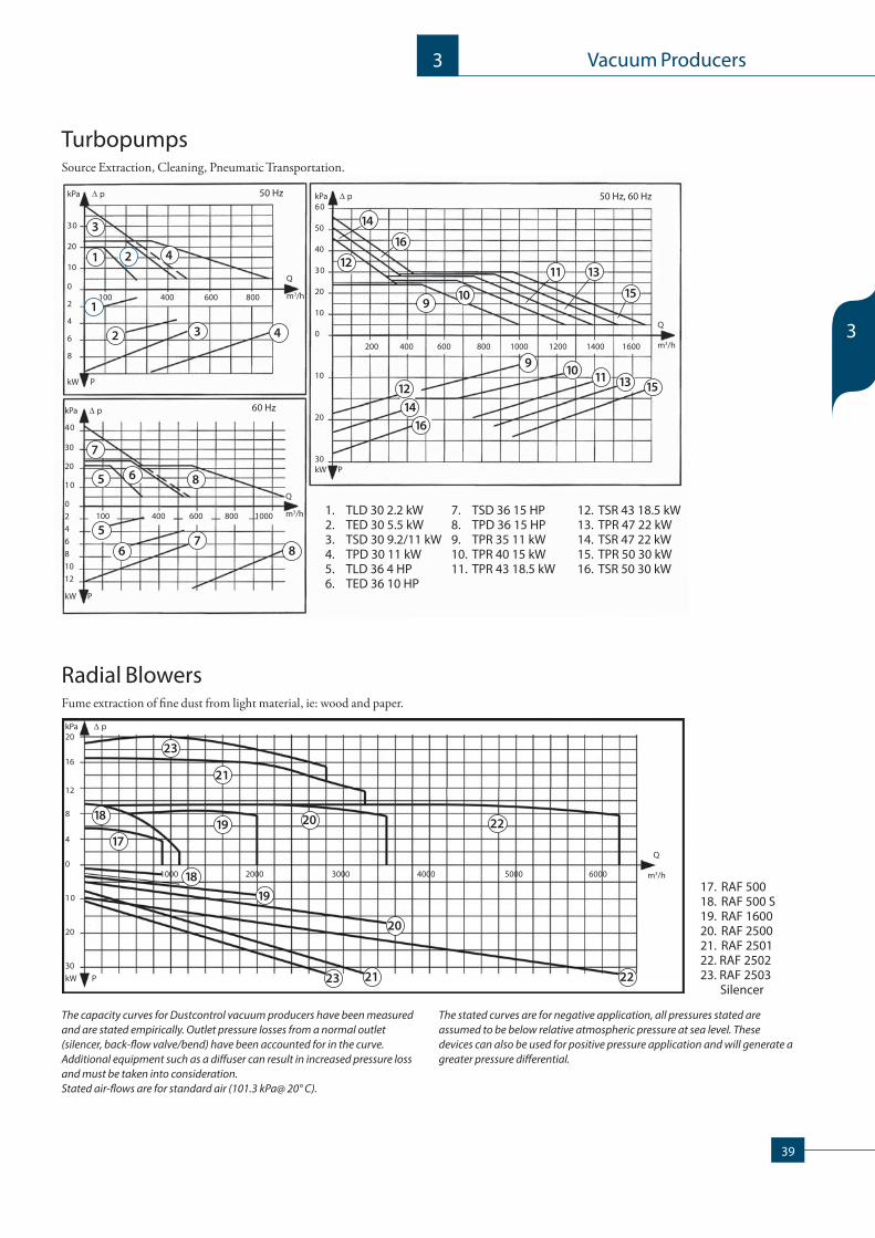
TurbopumpsSource Extraction, Cleaning, Pneu matic Trans portation.
The capacity curves for Dustcontrol vacuum producers have been measured and are stated empirically. Outlet pressure losses from a normal outlet (silencer, back-fl ow valve/bend) have been accounted for in the curve. Additional equipment such as a diff user can result in increased pressure loss and must be taken into consideration. Stated air-fl ows are for standard air (101.3 kPa@ 20° C).
Radial BlowersFume extraction of fi ne dust from light material, ie: wood and paper.
The stated curves are for negative application, all pressures stated are assumed to be below relative atmospheric pressure at sea level. These devices can also be used for positive pressure application and will generate a greater pressure diff erential.
17. RAF 500 18. RAF 500 S19. RAF 1600 20. RAF 250021. RAF 2501 22. RAF 250223. RAF 2503 Silencer
1. TLD 30 2.2 kW2. TED 30 5.5 kW3. TSD 30 9.2/11 kW4. TPD 30 11 kW5. TLD 36 4 HP6. TED 36 10 HP
7. TSD 36 15 HP8. TPD 36 15 HP9. TPR 35 11 kW10. TPR 40 15 kW11. TPR 43 18.5 kW
12. TSR 43 18.5 kW13. TPR 47 22 kW14. TSR 47 22 kW15. TPR 50 30 kW16. TSR 50 30 kW
39
3
3
Vacuum Producers

TPD 30/36 TED 30/36
TLD 30/36 TSD 30/36
LUBRICATION INTERVAL TLD 30 TLD 36 TED 30 TED 36 TPD 30 TSD 30 TSD 36 TPD 36 2.2 kW 4 HP 5.5 kW 10 HP 9.2/11 kW 9.2/11 kW 15 HP 15 HP
10000 h 10000 h 10000 h 10000 h 1500 h 1500 h 1500 h 1500 h
TLD/TED 30/36Turbopump TLD 30/36 and TED 30/36 are direct driven single stage units. To ensure constant pressure and that cooling air is avail-able to the pump when all outlets are closed, the tubing system should be equipped with a vacuum relief valve.
TPD 30/36Turbopump TPD 30/36 is a direct driven twin impeller parallel series con nected unit. To ensure constant pres sure and that cooling air is avail -able to the pump when all outlets are closed, the tubing system should be equipped with a vacuum relief valve.
TSD 30/36Turbopumps TSD 30/36 are direct driven twin impeller series connected units. Th is is used in demand ing applications where high vacuum levels are required. To ensure that cooling air is available to the pump when all outlets are closed, the turbo-pump can be equipped with a cooling air inlet.
These direct driven units are extremely reliable and have low service require-ments. Always change the O Ring when repacking the outboard bearing in the TSD and TPD pump.400 g Grease Cartridge for Dustcontrol Turbopumps, Part No 9928
Power Hz TLD 30 TLD 36 TED 30 TED 36 TPD 30 TSD 30 TSD 36 TPD 36
Consumption 2.2 kW 4 HP 5.5 kW 10 HP 11 kW 9.2 kW 15 HP S 15 HP P
230/400 V 50 4322
230 V 50 4326 4910 4907
400 V 50 4126 4911 4908
230/460 V 60 419006
460 V US/CAN 60 419306 479700 488100
600 V CAN 60 419004 419101 4615
40
3Vacuum Producers

3014
30693055
49423054
300730783077
3037
3014
3069
30404942
3055
3069
3014
4477
3031
30404942
3055
3031
4477
402614069740698
42297
3037
4477
4942/3195
8001
TPD 30/36
TED 30/36
TSD 30/36
TLD 30/36
4659
kPa Pu
40
30
20
10
024681012
kW P
100 400 600 800 1000
Q
m3/h/cfm
7
5 6 8
87
56
60 Hz
kPa Pu
30
20
10
0
2
4
6
8
kW P
100 400 600 800
Q
m3/h
3
1 2 4
1
23 4
50 Hz
AccessoriesPart No 3037 Console 500 mm (2 req’d)For wall installation of TLD 30/36.Part No 4477 Pump ChassisFor separate mounting of TED 30/36, TPD 30/36 and TSD 30/36.Part No 4942 Silencer 100 300/200Used for silencing of 76 mm vacuum valve and also exhaust silencing on 2.5–11 kW/4–16.9 HP turbopump. For accompanying tubing details, see installation example.Part No 3195 Silencer 80300/180Used for silencing of 50 mm vacuum valve. Part No 8253 Vacuum Relief Valve 50 mmUsed with TLD 30/36. Th e vacuum relief valve is installed on the tubing system (inlet side) on a branch tube. Th is delivers cooling air to the turbopump and can be adjusted for the desired vacuum level in the system.Part No 8001 Vacuum Relief Valve 76 mmUsed with TED 30/36 and TPD 30/36. Th e vacuum relief valve is installed on the tubing system (inlet side) on a branch tube. Th is delivers cooling air to the turbopump and can be adjusted for the desired vacuum level in the system.Part No 40595 Cooling air inlet with silencer for TSD 30/36Cooling air is introduced to the turbopump between stages so the unit can be driven with all outlets closed without the risk of overheating.Part No 42297 Back Flow Valve Ø108Installed on the inlet side of the turbopump when two or more units are parallel installed.
Silencing Covers. Th e silencing covers will reduce the sound level by 4 dB.Part No 42988 Silencing Cover for TLD 30
Part No 40697 Silencing Cover for TED 30 5.5 kW
Part No 40698 Silencing Cover for TED 30 9.2 kW
Part No 4659 Intermediate piece Ø108
Figure shows available capacity in an extraction system.
*) Turbopump with cooling air inlet.
Installation Example, Silencers
Capacity and Power ConsumptionTECHNICAL DATA, description TLD 30 TLD 36 TED 30 TED 36 TPD 30 TSD 30 TSD 36 TPD 36
Power Supply Hz 50 60 50 60 50 50 60 60
Pump RPM 3000 3600 3000 3600 3000 3000 3600 3600
Weight kg/lb 30 66 65 143.3 90 90 242.5 242.5
Max dP kPa 20 22* 23* 24* 21* 40 43 20
Nominal Pressure kPa 18 20 18 20 18 30 32 17
Max Q m3/h/cfm 260 176.6 450 353 900 450 329.6 618
Sound Level of
Unit 1m dB(A) 75 75 75 75 75 75 75 75
Inlet/Outlet Ø mm 50/50 2”/2” 108/108 4.25”/4.25” 108/108 108/108 4.25”/4.25” 4.25”/4.25”
1. TLD 30 2.2 kW2. TED 30 5.5 kW3. TSD 30 9.2/11 kW *)
4. TPD 30 11 kW
5. TLD 36 4 HP6. TED 36 10 HP7. TSD 36 15 HP *)
8. TPD 36 15 HP
* Standard DC Green System Max 22 kPa
41
3
3
Vacuum Producers

TPR
TSR
TPRTurbopumps with TPR designation are parallel connected twin impeller belt driven units. Cooling air is introduced into the unit through an adjustable vacuum relief valve. Th e vacuum pressure in the system can be held constant when diff erent outlets are opened. Th e turbopumps are equipped with thermal overload protection on the outboard bearing which will trip out when bearing temperature becomes excessive. A back fl ow valve is built into the unit on the inlet side.
Dimensions, Installation Example
TSRTurbopumps with TSR designation are series connected two stage belt driven units. Cooling air is introduced into the pump through a slot between the two stages. In this way the second stage cools the fi rst stage indirectly, allowing the pump to run at extremely high vacuum and low airfl ow without overheating. Th e turbopumps are equipped with thermal overload protection on the outboard bearing which will trip out when bearing temperature becomes excessive. A back fl ow valve must be optionally installed on the inlet side of the unit when several units are to be installed in parallel.
Power Consumption Hz TPR 35 TPR 40 TPR 43 TSR 43 TPR 47 TSR 47/48 TPR 50 TSR 50/52
230 V 50 106802/15 kW 107202/18.5 kW 107252/18.5 kW 107702/22 kW 107752/22 kW 109202/30 kW 109252/30 kW
400 V 50 106600/11 kW 106800/15 kW 107200/18.5 kW 107250/18.5 kW 107700/22 kW 107750/22 kW 109200/30 kW 109250/30 kW
460 V USA/CAN 60 106805/20 hp 107207/25 hp 107257/25 hp 107707/30 hp 107757/30 hp 109207/40 hp 109257/40 hp
600 V CAN 60 106806/20 hp 107206/25 hp 107256/25 hp 107706/30 hp 107756/30 hp 109206/40 hp 109256/40 hp
42
3Vacuum Producers

Pump RPM rpm 3500 4000 4300 4300 4700 4700 5000 5000 5300
Weight kg 400 400 430 430 450 450 530 530 530
Max dP kPa 22 26* 28* 46 29* 50 30* 54 30*
Nominal Pressure kPa 20 20 20 35 21 37 23 40 23
Max Q m3/h 1000 1200 1400 650 1500 700 1600 800 1900
Sound Level of
Unit 1 m
dB(A) 66 66 66 66 66 66 66 66 66
Inlet/Outlet Ømm 160/160 160/160 160/160 108/108 160/160 108/108 160/160 108/108 108/108
TECHNICAL DATA description TPR 35 TPR 40 TPR 43 TSR 43 TPR 47 TSR 47/48 TPR 50 TSR 50/52 TPR 53
A
kPa Pu
7
64
8
1
7532
6
8
253
Q
m3/h
kW P
30
20
10
0
50
40
10
20
30
1. TPR 35 2. TPR 40 3. TPR 43 4. TSR 43 5. TPR 47 6. TSR 47/48 7. TPR 50 8. TSR 50/52 9. TPR 53
200 400 600 800 1000 1200 1400 1600
1
4
60
Part No 8051 Back Flow Valve 160 mmInstalled on the inlet side of the TSR when two or more units are parallel installed.
Capacity and Power Consumption
The diagram shows available capacity for an extraction system.
AccessoriesSilencerPart No Conn Dimensions3182 Ø160 L=1200, Ø3553183 Ø160 L=600, Ø3553184 Ø160 L=600, Ø260
Lubrication Interval
Grease for Dustcontrol Turbopumps, Part No 9928
p TPR 35 TPR 40 TPR 43 TSR 43 TPR 47 TSR 47/48 TPR 50 TSR 50/52
22 kPa 1500 h 1500 h 1500 h – 1500 h – 1500 h –
25 kPa 750 h 750 h 1500 h – 1500 h – 1500 h –
28 kPa – – 1000 h – 1000 h – 1000 h –
30 kPa – – – 1500 h – 1500 h 750 h 1500 h
40 kPa – – – 1000 h – 1000 h – 1000 h
Part No A
– 75 dB(A)
3184 64 dB(A)
3182 62 dB(A)
* Standard DC Green System Max 22 kPa
9
9
43
3
3
Vacuum Producers
kPa Pu
10
8
6
4
2
0
1
2
3
4
5
kW P
Q
m3/h
RAF 500S
42297
4476
2 x 3037
A B C D
RAF 500 450 157 550 510
RAF 500S 460 325 725 685
RAF 500RAF 500S
200 400 600 800 1000
RAF 500
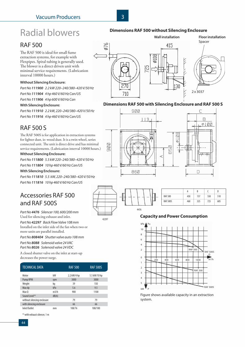
Dimensions RAF 500 without Silencing Enclosure
Dimensions RAF 500 with Silencing Enclosure and RAF 500 S
Capacity and Power Consumption
Accessories RAF 500 and RAF 500SPart No 4476 Silencer 100, 600/200 mmUsed for silencing exhaust and inlet.Part No 42297 Back Flow Valve 108 mmInstalled on the inlet side of the fan when two or more units are parallel installed. Part No 808404 Shutter valve auto 108 mm
Part No 8088 Solenoid valve 24 VACPart No 8026 Solenoid valve 24 VDC
A closed shutter valve on the inlet at start-up decreases the power surge.
Wall installation Floor installationSpacer
Radial blowers
Th e RAF 500 is ideal for small fume extraction systems, for example with Flexpipes. Spiral tubing is generally used. Th e blower is a direct driven unit with minimal service requirements. (Lubrication interval 10000 hours.)
RAF 500 STh e RAF 500S is for application in extraction systems for lighter dust, ie: wood dust. It is a twin wheel, series connected unit. Th e unit is direct drive and has minimal service requirements. (Lubrication interval 10000 hours.)
TECHNICAL DATA RAF 500 RAF 500S
Motor kW 2.2 kW/4 hp 5.5 kW/10 hp
Pump RPM rpm 3000 3000
Weight kg 39 150
Max dp kPa 5.6 9.5
Max Q m3/h 900 1100
Sound Level *) dB(A)
without silencing enclosure 79 79
with silencing enclosure 66 66
Inlet/Outlet mm 108/76 108/100
*) with exhaust silencer, 1 m
Figure shows available capacity in an extraction system.
Without Silencing Enclosure:
Part No 111900 2.2 kW 220–240/380–420 V/50 Hz
Part No 111904 4 hp 460 V/60 Hz Can/US
Part No 111906 4 hp 600 V/60 Hz Can
With Silencing Enclosure:
Part No 111910 2.2 kW, 220–240/380–420 V/50 Hz
Part No 111916 4 hp 460 V/60 Hz Can/US
Without Silencing Enclosure:
Part No 111800 5.5 kW 220–240/380–420 V/50 Hz
Part No 111804 10 hp 460 V/60 Hz Can/US
With Silencing Enclosure:
Part No 111810 5.5 kW, 220–240/380–420 V/50 Hz
Part No 111816 10 hp 460 V/60 Hz Can/US
RAF 500
44
3Vacuum Producers
kPa Pu
8
4
0
10
20kW P
1000 2000 3000
Q
m3/h
RAF 1600
RAF 1600
RAF 2500
RAF 2500
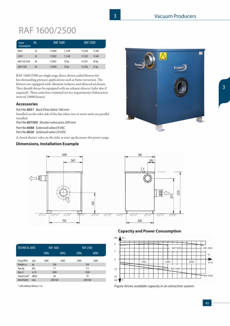
RAF 1600/2500
RAF 1600/2500 are single stage direct driven radial blowers for less demand ing pressure applications such as fume extraction. Th e blowers are equipped with vibration isolators and silenced enclosure. Th ey should always be equip ped with an exhaust silencer (inlet also if required). Th ese units have minimal service requirements (lubrication interval 10000 hours).
Accessories
Part No 8051 Back Flow Valve 160 mmInstalled on the inlet side of the fan when two or more units are parallel installed. Part No 807500 Shutter valve auto 200 mm
Part No 8088 Solenoid valve24 VACPart No 8026 Solenoid valve 24 VDC
A closed shutter valve on the inlet at start-up decreases the power surge.
TECHNICAL DATA RAF 1600 RAF 2500
50Hz 60Hz 50Hz 60Hz
Pump RPM rpm 3000 3600 3000 3600
Weight ca kg 290 330
Max dp kPa 7.7 9.3
Max Q m3/h 2000 3500
Sound Level* dB(A) 68 70
Inlet/Outlet mm 200/160 200/160
* with exhaust silencer, 1 m.
Dimensions, Installation Example
Capacity and Power Consumption
Power Hz RAF 1600 RAF 2500Consumption
Figure shows available capacity in an extraction system.
400 V 50 112000 7,5 kW 112100 15 kW
230 V 50 112002 7,5 kW 112102 15 kW
460 V US/CAN 60 112007 10 hp 112107 20 hp
600 V CAN 60 112006 10 hp 112106 25 hp
45
3
3
Vacuum Producers

RAF 2501/RAF 2503
RAF 2502
V Hz Motor Part No
400 50 30 kW 112300
230 50 30 kW 112302
460 USA/CAN 60 40 hp 112304
600 60 40 hp 112306
V Hz Motor Part No
400 50 30 kW 112200
230 50 30 kW 112202
460 USA/CAN 60 40 hp 112204
600 60 40 hp 112206
Th e RAF 2501 is applied in extraction systems requiring large air-fl ows for lighter types of dust and cleaning. Pressure gene ration is achieved through two series connected stages. Th e unit is equipped with vibration isolation and a silenced enclosure. Th e unit should always be equipped with an exhaust silencer (inlet also if required). Th e unit is direct driven and has minimal service requirements (lubrication interval 10000 hours).
RAF 2501
TECHNICAL DATA RAF 2501 RAF 2502 RAF 2503 50Hz 60Hz 50Hz 60Hz 50 Hz
Pump RPM rpm 3000 3600 3000 3600 3000
Weight ca kg 440 430 450
Max dp kPa 17 9.4 20
Max Q m3/h 3300 6200 2800
Sound Level* dB(A) 74 74 74
Inlet/Outlet mm 200/160 2x200/2x160 200/160
* with exhaust silencer, 1 m.
RAF 2502
Th e RAF 2502 is applied in extraction systems requiring large air-fl ows such as systems for fume extraction. RAF 2502 work with two parallel impellers. Th e unit is equipped with vibration isolation and a silenced enclosure. Th e unit should always be equipped with an exhaust silencer (inlet also if required). Th e unit is direct driven and has minimal service requirements (lubrication interval 10000 hours).
RAF 2503V Hz kW Part No
400 50 30 112400
Pressure gene ration is achieved through two series connected stages. Th e unit is equipped with vibration isolation and a silenced enclosure. Th e unit should always be equipped with an exhaust silencer (inlet also if required). Th e unit is direct driven and has minimal service requirements (lubrication interval 10000 hours). RAF 2503 developes a maximum negative pressure of 20 kPa. Note though that the maximum airfl ow is 2800 m3/h. Above this, the power consumption would be too large for the 30 kW motor, so the design of the system must throttle to this level for all cases. Accessories
Accessories
Part No 8051 Back Flow Valve 160 mmInstalled on the inlet side of the fan when two or more units are parallel installed. Part No 807500 Shutter valve auto 200 mm */
Part No 8088 Solenoid valve24 VACA closed shutter valve on the inlet at start-up decreases the power surge.*/ Note! Shutter valve Ø 200/Ø 250 only for single step fans (10 kPa).
46
3Vacuum Producers

Ø 160
Ø 160
Ø 160
96 100 102
75 78 81
68 72 71
321
321
kPa
20
16
12
8
4
0
10
20
30
kW P
Pu
1000 2000 3000 4000 5000 6000 m3/h
Q
RAF2501
RAF2502
RAF2503
RAF2503RAF2501 RAF2502
Fan SilencersIn order to decrease the noise level of our fans, RAF 1600 – 2503, an in-line silencer must be installed on the exhaust duct. Several examples are illustrated of how noise level measurements can be aff ected. It is not unusual to obtain measurements of up to 110–120 dB(A) in com-pletely non-silenced installations.
Part No Conn. Dimensions3182 Ø160 L=1200, Ø355 mm3183 Ø160 L=600, Ø355 mm3184 Ø160 L=600, Ø260 mm
SilencerØ160 x 600 x 260 (Part No 3184)
SilencerØ160 x 1200 x 260 (Part No. 3182)
Capacity and Power Consumption
Figure shows available capacity in an extraction system.
47
3
3
Vacuum Producers

S 34000, RAF 2500TPR 35–TPR 50, S 32000–S 34000, F 20000
S 34000RAF 2500
S 34000
RAF 2500
TPR 35– TPR 50
S 32000– S 34000
F 20000
TPR 35– TPR 50
S 32000– S 34000
RAF 2501, S 34000 RAF 2502, S 34000X
RAF 2502
RAF 2502
S 34000X
S 34000X
S 34000
S 34000
RAF 2501
RAF 2501
F 20000
Installation Examples
48
3Vacuum Producers