International Space Station Ground Handbook Specific ISS … · JSC-48516-3A International Space...
55
JSC-48516-3A International Space Station Ground Handbook Specific ISS-3A Mission Operations Directorate Operations Division Final June 13, 2000
Transcript of International Space Station Ground Handbook Specific ISS … · JSC-48516-3A International Space...
JSC-48516-3A
International Space Station
Ground Handbook
Specific
ISS-3A
Mission Operations Directorate
Operations Division
Final
June 13, 2000
National Aeronautics andSpace Administration
Lyndon B. Johnson Space CenterHouston, Texas
United StatesSystems Operations Data File JSC-48516-3A
INTERNATIONAL SPACE STATION
GROUND HANDBOOK - SPECIFIC
ISS-3A
FINALJune 13, 2000
APPROVED BY:
___________________________________________Brenda TracyBook Manager
___________________________________________Michael T. Hurt
Supervisor, Procedures and Portable Computing Section
___________________________________________Kent H. Adams
3A SODF Coordinator
ACCEPTED BY:
___________________________________________Michael T. HurtSODF Manager
This document is under the configuration control of the Systems Operations DataFile Control Board (SODFCB).

United StatesSystems Operations Data File JSC-48516-3A
13 JUN 00 GND/3A/FINii
Incorporates the following:
CR: U_140U_144
13 JUN 00 iii GND/3A/FIN
INTERNATIONAL SPACE STATION
GROUND HANDBOOK - SPECIFIC
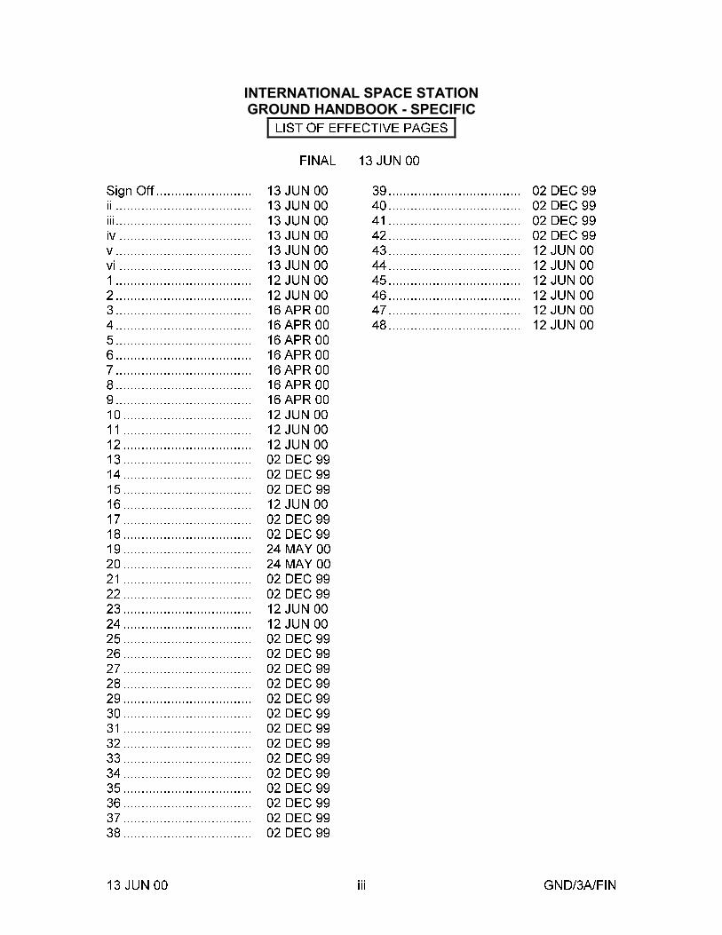
LIST OF EFFECTIVE PAGES
FINAL 13 JUN 00
Sign Off .......................... 13 JUN 00ii ..................................... 13 JUN 00iii..................................... 13 JUN 00iv .................................... 13 JUN 00v ..................................... 13 JUN 00vi .................................... 13 JUN 001 ..................................... 12 JUN 002 ..................................... 12 JUN 003 ..................................... 16 APR 004 ..................................... 16 APR 005 ..................................... 16 APR 006 ..................................... 16 APR 007 ..................................... 16 APR 008 ..................................... 16 APR 009 ..................................... 16 APR 0010 ................................... 12 JUN 0011 ................................... 12 JUN 0012 ................................... 12 JUN 0013 ................................... 02 DEC 9914 ................................... 02 DEC 9915 ................................... 02 DEC 9916 ................................... 12 JUN 0017 ................................... 02 DEC 9918 ................................... 02 DEC 9919 ................................... 24 MAY 0020 ................................... 24 MAY 0021 ................................... 02 DEC 9922 ................................... 02 DEC 9923 ................................... 12 JUN 0024 ................................... 12 JUN 0025 ................................... 02 DEC 9926 ................................... 02 DEC 9927 ................................... 02 DEC 9928 ................................... 02 DEC 9929 ................................... 02 DEC 9930 ................................... 02 DEC 9931 ................................... 02 DEC 9932 ................................... 02 DEC 9933 ................................... 02 DEC 9934 ................................... 02 DEC 9935 ................................... 02 DEC 9936 ................................... 02 DEC 9937 ................................... 02 DEC 9938 ................................... 02 DEC 99
39.................................... 02 DEC 9940.................................... 02 DEC 9941.................................... 02 DEC 9942.................................... 02 DEC 9943.................................... 12 JUN 0044.................................... 12 JUN 0045.................................... 12 JUN 0046.................................... 12 JUN 0047.................................... 12 JUN 0048.................................... 12 JUN 00

13 JUN 00 GND/3A/FINiv
This Page Intentionally Blank
13 JUN 00 GND/3A/FINv
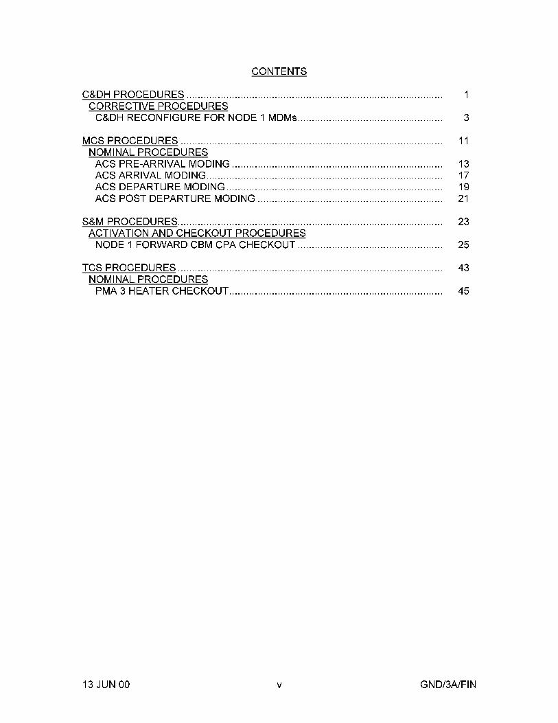
CONTENTS
C&DH PROCEDURES .......................................................................................... 1CORRECTIVE PROCEDURESC&DH RECONFIGURE FOR NODE 1 MDMs................................................... 3
MCS PROCEDURES ............................................................................................ 11NOMINAL PROCEDURESACS PRE-ARRIVAL MODING .......................................................................... 13ACS ARRIVAL MODING................................................................................... 17ACS DEPARTURE MODING............................................................................ 19ACS POST DEPARTURE MODING ................................................................. 21
S&M PROCEDURES............................................................................................. 23ACTIVATION AND CHECKOUT PROCEDURESNODE 1 FORWARD CBM CPA CHECKOUT ................................................... 25
TCS PROCEDURES ............................................................................................. 43NOMINAL PROCEDURESPMA 3 HEATER CHECKOUT........................................................................... 45

13 JUN 00 GND/3A/FINvi
This Page Intentionally Blank

12 JUN 00
C&DH PROCEDURES
C&DH
1

12 JUN 00
This Page Intentionally Blank
C&DH
2
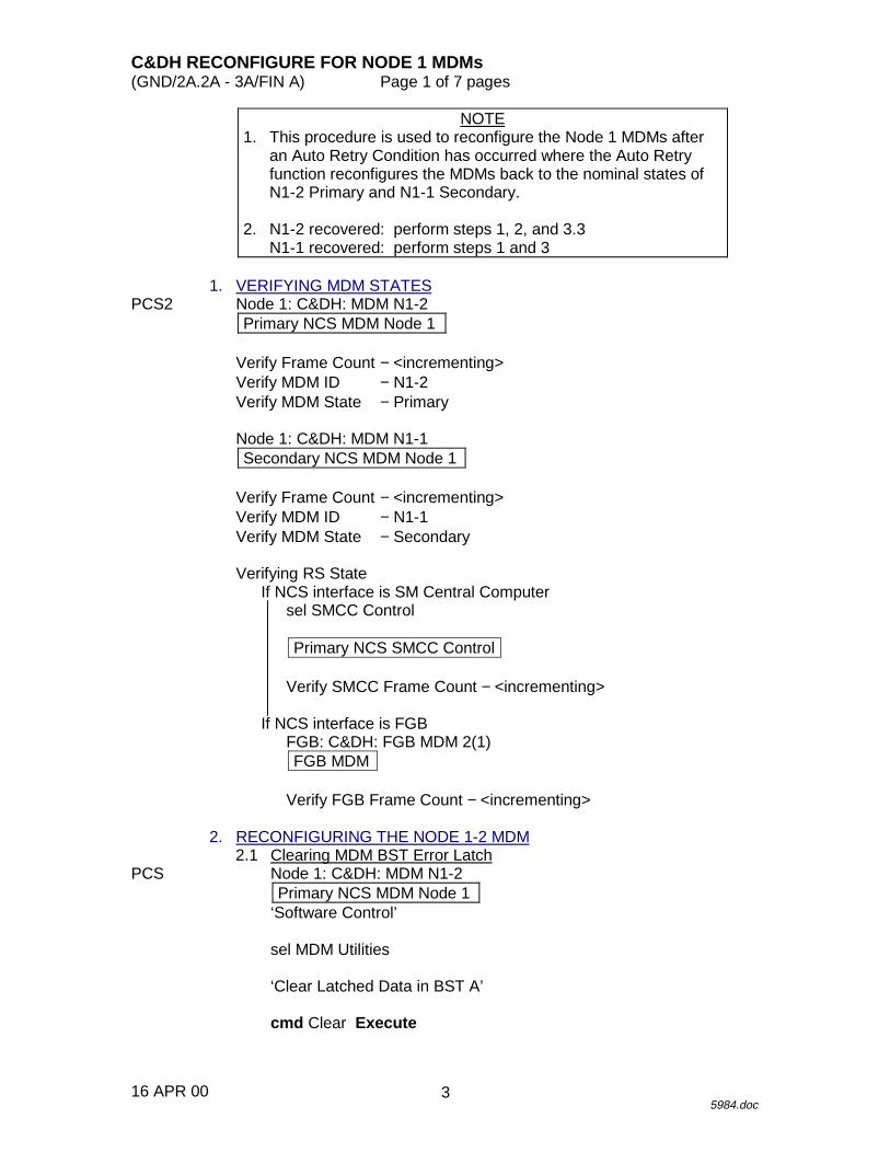
C&DH RECONFIGURE FOR NODE 1 MDMs(GND/2A.2A - 3A/FIN A) Page 1 of 7 pages
16 APR 005984.doc
NOTE1. This procedure is used to reconfigure the Node 1 MDMs after
an Auto Retry Condition has occurred where the Auto Retryfunction reconfigures the MDMs back to the nominal states ofN1-2 Primary and N1-1 Secondary.
2. N1-2 recovered: perform steps 1, 2, and 3.3N1-1 recovered: perform steps 1 and 3
1. VERIFYING MDM STATESPCS2 Node 1: C&DH: MDM N1-2
Primary NCS MDM Node 1
Verify Frame Count − <incrementing>Verify MDM ID − N1-2Verify MDM State − Primary
Node 1: C&DH: MDM N1-1Secondary NCS MDM Node 1
Verify Frame Count − <incrementing>Verify MDM ID − N1-1Verify MDM State − Secondary
Verifying RS StateIf NCS interface is SM Central Computer
sel SMCC Control
Primary NCS SMCC Control
Verify SMCC Frame Count − <incrementing>
If NCS interface is FGBFGB: C&DH: FGB MDM 2(1)FGB MDM
Verify FGB Frame Count − <incrementing>
2. RECONFIGURING THE NODE 1-2 MDM2.1 Clearing MDM BST Error Latch
PCS Node 1: C&DH: MDM N1-2Primary NCS MDM Node 1
‘Software Control’
sel MDM Utilities
‘Clear Latched Data in BST A’
cmd Clear Execute
3
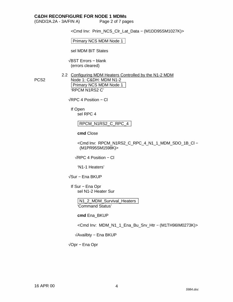
C&DH RECONFIGURE FOR NODE 1 MDMs(GND/2A.2A - 3A/FIN A) Page 2 of 7 pages
16 APR 005984.doc
<Cmd Inv: Prim_NCS_Clr_Lat_Data − (M1DD95SM1027K)>
Primary NCS MDM Node 1
sel MDM BIT States
√BST Errors − blank(errors cleared)
2.2 Configuring MDM Heaters Controlled by the N1-2 MDMPCS2 Node 1: C&DH: MDM N1-2
Primary NCS MDM Node 1‘RPCM N1RS2 C’
√RPC 4 Position − Cl
If Opensel RPC 4
RPCM_N1RS2_C_RPC_4
cmd Close
<Cmd Inv: RPCM_N1RS2_C_RPC_4_N1_1_MDM_SDO_1B_Cl −(M1PR95SM1598K)>
√RPC 4 Position − Cl
‘N1-1 Heaters’
√Sur − Ena BKUP
If Sur − Ena Oprsel N1-2 Heater Sur
N1_2_MDM_Survival_Heaters‘Command Status’
cmd Ena_BKUP
<Cmd Inv: MDM_N1_1_Ena_Bu_Srv_Htr − (M1TH96IM0273K)>
√Availbty − Ena BKUP
√Opr − Ena Opr
4
C&DH RECONFIGURE FOR NODE 1 MDMs(GND/2A.2A - 3A/FIN A) Page 3 of 7 pages
16 APR 005984.doc
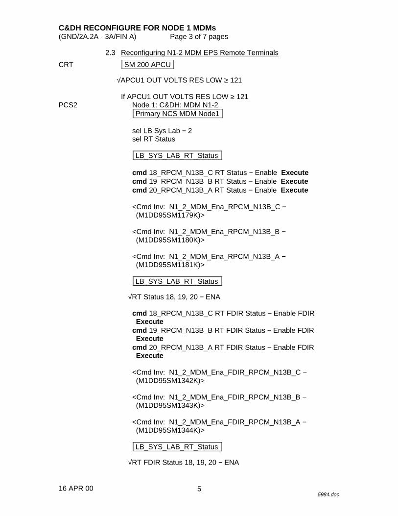
2.3 Reconfiguring N1-2 MDM EPS Remote Terminals
CRT SM 200 APCU
√APCU1 OUT VOLTS RES LOW ≥ 121
If APCU1 OUT VOLTS RES LOW ≥ 121PCS2 Node 1: C&DH: MDM N1-2
Primary NCS MDM Node1
sel LB Sys Lab − 2sel RT Status
LB_SYS_LAB_RT_Status
cmd 18_RPCM_N13B_C RT Status − Enable Executecmd 19_RPCM_N13B_B RT Status − Enable Executecmd 20_RPCM_N13B_A RT Status − Enable Execute
<Cmd Inv: N1_2_MDM_Ena_RPCM_N13B_C −(M1DD95SM1179K)>
<Cmd Inv: N1_2_MDM_Ena_RPCM_N13B_B −(M1DD95SM1180K)>
<Cmd Inv: N1_2_MDM_Ena_RPCM_N13B_A −(M1DD95SM1181K)>
LB_SYS_LAB_RT_Status
√RT Status 18, 19, 20 − ENA
cmd 18_RPCM_N13B_C RT FDIR Status − Enable FDIRExecute
cmd 19_RPCM_N13B_B RT FDIR Status − Enable FDIRExecute
cmd 20_RPCM_N13B_A RT FDIR Status − Enable FDIRExecute
<Cmd Inv: N1_2_MDM_Ena_FDIR_RPCM_N13B_C −(M1DD95SM1342K)>
<Cmd Inv: N1_2_MDM_Ena_FDIR_RPCM_N13B_B −(M1DD95SM1343K)>
<Cmd Inv: N1_2_MDM_Ena_FDIR_RPCM_N13B_A −(M1DD95SM1344K)>
LB_SYS_LAB_RT_Status
√RT FDIR Status 18, 19, 20 − ENA
5
C&DH RECONFIGURE FOR NODE 1 MDMs(GND/2A.2A - 3A/FIN A) Page 4 of 7 pages
16 APR 005984.doc
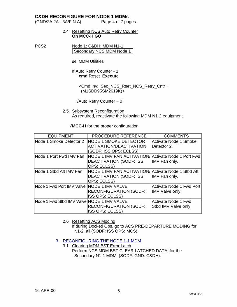
2.4 Resetting NCS Auto Retry CounterOn MCC-H GO
PCS2 Node 1: C&DH: MDM N1-1Secondary NCS MDM Node 1
sel MDM Utilities
If Auto Retry Counter - 1cmd Reset Execute
<Cmd Inv: Sec_NCS_Rset_NCS_Retry_Cntr −(M1SDD95SM2619K)>
√Auto Retry Counter − 0
2.5 Subsystem ReconfigurationAs required, reactivate the following MDM N1-2 equipment.
√MCC-H for the proper configuration
EQUIPMENT PROCEDURE REFERENCE COMMENTSNode 1 Smoke Detector 2 NODE 1 SMOKE DETECTOR
ACTIVATION/DEACTIVATION(SODF: ISS OPS: ECLSS)
Activate Node 1 SmokeDetector 2.
Node 1 Port Fwd IMV Fan NODE 1 IMV FAN ACTIVATION/DEACTIVATION (SODF: ISSOPS: ECLSS)
Activate Node 1 Port FwdIMV Fan only.
Node 1 Stbd Aft IMV Fan NODE 1 IMV FAN ACTIVATION/DEACTIVATION (SODF: ISSOPS: ECLSS)
Activate Node 1 Stbd AftIMV Fan only.
Node 1 Fwd Port IMV Valve NODE 1 IMV VALVERECONFIGURATION (SODF:ISS OPS: ECLSS)
Activate Node 1 Fwd PortIMV Valve only.
Node 1 Fwd Stbd IMV Valve NODE 1 IMV VALVERECONFIGURATION (SODF:ISS OPS: ECLSS)
Activate Node 1 FwdStbd IMV Valve only.
2.6 Resetting ACS ModingIf during Docked Ops, go to ACS PRE-DEPARTURE MODING forN1-2, all (SODF: ISS OPS: MCS).
3. RECONFIGURING THE NODE 1-1 MDM3.1 Clearing MDM BST Error Latch
Perform NCS MDM BST CLEAR LATCHED DATA, for theSecondary N1-1 MDM, (SODF: GND: C&DH).
6
C&DH RECONFIGURE FOR NODE 1 MDMs(GND/2A.2A - 3A/FIN A) Page 5 of 7 pages
16 APR 005984.doc
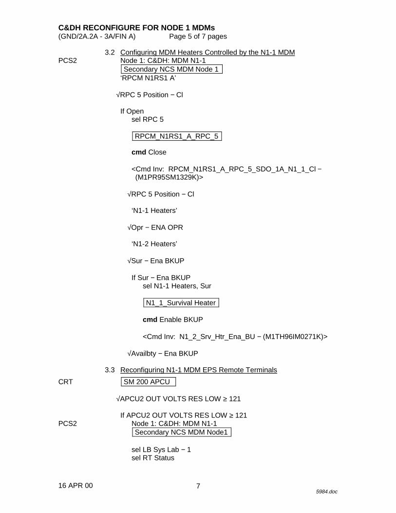
3.2 Configuring MDM Heaters Controlled by the N1-1 MDMPCS2 Node 1: C&DH: MDM N1-1
Secondary NCS MDM Node 1‘RPCM N1RS1 A’
√RPC 5 Position − Cl
If Opensel RPC 5
RPCM_N1RS1_A_RPC_5
cmd Close
<Cmd Inv: RPCM_N1RS1_A_RPC_5_SDO_1A_N1_1_Cl −(M1PR95SM1329K)>
√RPC 5 Position − Cl
‘N1-1 Heaters’
√Opr − ENA OPR
‘N1-2 Heaters’
√Sur − Ena BKUP
If Sur − Ena BKUPsel N1-1 Heaters, Sur
N1_1_Survival Heater
cmd Enable BKUP
<Cmd Inv: N1_2_Srv_Htr_Ena_BU − (M1TH96IM0271K)>
√Availbty − Ena BKUP
3.3 Reconfiguring N1-1 MDM EPS Remote Terminals
CRT SM 200 APCU
√APCU2 OUT VOLTS RES LOW ≥ 121
If APCU2 OUT VOLTS RES LOW ≥ 121PCS2 Node 1: C&DH: MDM N1-1
Secondary NCS MDM Node1
sel LB Sys Lab − 1sel RT Status
7
C&DH RECONFIGURE FOR NODE 1 MDMs(GND/2A.2A - 3A/FIN A) Page 6 of 7 pages
16 APR 005984.doc
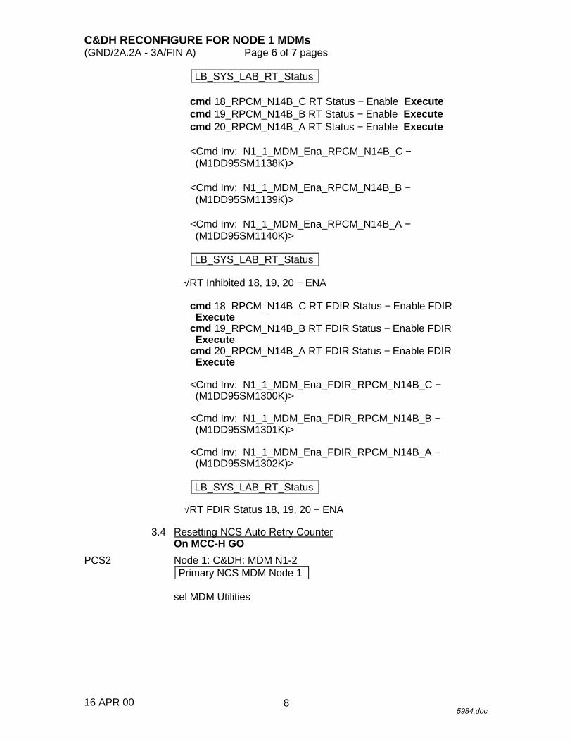
LB_SYS_LAB_RT_Status
cmd 18_RPCM_N14B_C RT Status − Enable Executecmd 19_RPCM_N14B_B RT Status − Enable Executecmd 20_RPCM_N14B_A RT Status − Enable Execute
<Cmd Inv: N1_1_MDM_Ena_RPCM_N14B_C −(M1DD95SM1138K)>
<Cmd Inv: N1_1_MDM_Ena_RPCM_N14B_B −(M1DD95SM1139K)>
<Cmd Inv: N1_1_MDM_Ena_RPCM_N14B_A −(M1DD95SM1140K)>
LB_SYS_LAB_RT_Status
√RT Inhibited 18, 19, 20 − ENA
cmd 18_RPCM_N14B_C RT FDIR Status − Enable FDIRExecute
cmd 19_RPCM_N14B_B RT FDIR Status − Enable FDIRExecute
cmd 20_RPCM_N14B_A RT FDIR Status − Enable FDIRExecute
<Cmd Inv: N1_1_MDM_Ena_FDIR_RPCM_N14B_C −(M1DD95SM1300K)>
<Cmd Inv: N1_1_MDM_Ena_FDIR_RPCM_N14B_B −(M1DD95SM1301K)>
<Cmd Inv: N1_1_MDM_Ena_FDIR_RPCM_N14B_A −(M1DD95SM1302K)>
LB_SYS_LAB_RT_Status
√RT FDIR Status 18, 19, 20 − ENA
3.4 Resetting NCS Auto Retry CounterOn MCC-H GO
PCS2 Node 1: C&DH: MDM N1-2Primary NCS MDM Node 1
sel MDM Utilities
8
C&DH RECONFIGURE FOR NODE 1 MDMs(GND/2A.2A - 3A/FIN A) Page 7 of 7 pages
16 APR 005984.doc
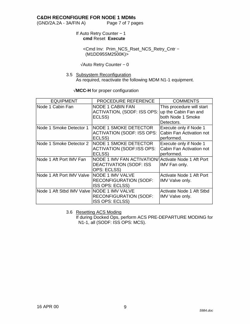
If Auto Retry Counter − 1cmd Reset Execute
<Cmd Inv: Prim_NCS_Rset_NCS_Retry_Cntr −(M1DD95SM2500K)>
√Auto Retry Counter − 0
3.5 Subsystem ReconfigurationAs required, reactivate the following MDM N1-1 equipment.
√MCC-H for proper configuration
EQUIPMENT PROCEDURE REFERENCE COMMENTSNode 1 Cabin Fan NODE 1 CABIN FAN
ACTIVATION, (SODF: ISS OPS:ECLSS)
This procedure will startup the Cabin Fan andboth Node 1 SmokeDetectors.
Node 1 Smoke Detector 1 NODE 1 SMOKE DETECTORACTIVATION (SODF: ISS OPS:ECLSS)
Execute only if Node 1Cabin Fan Activation notperformed.
Node 1 Smoke Detector 2 NODE 1 SMOKE DETECTORACTIVATION (SODF:ISS OPS:ECLSS)
Execute only if Node 1Cabin Fan Activation notperformed.
Node 1 Aft Port IMV Fan NODE 1 IMV FAN ACTIVATION/DEACTIVATION (SODF: ISSOPS: ECLSS)
Activate Node 1 Aft PortIMV Fan only.
Node 1 Aft Port IMV Valve NODE 1 IMV VALVERECONFIGURATION (SODF:ISS OPS: ECLSS)
Activate Node 1 Aft PortIMV Valve only.
Node 1 Aft Stbd IMV Valve NODE 1 IMV VALVERECONFIGURATION (SODF:ISS OPS: ECLSS)
Activate Node 1 Aft StbdIMV Valve only.
3.6 Resetting ACS ModingIf during Docked Ops, perform ACS PRE-DEPARTURE MODING forN1-1, all (SODF: ISS OPS: MCS).
9

12 JUN 00
This Page Intentionally Blank
10

12 JUN 00
MCS PROCEDURES
MCS
11

12 JUN 00
This Page Intentionally Blank
MCS
12
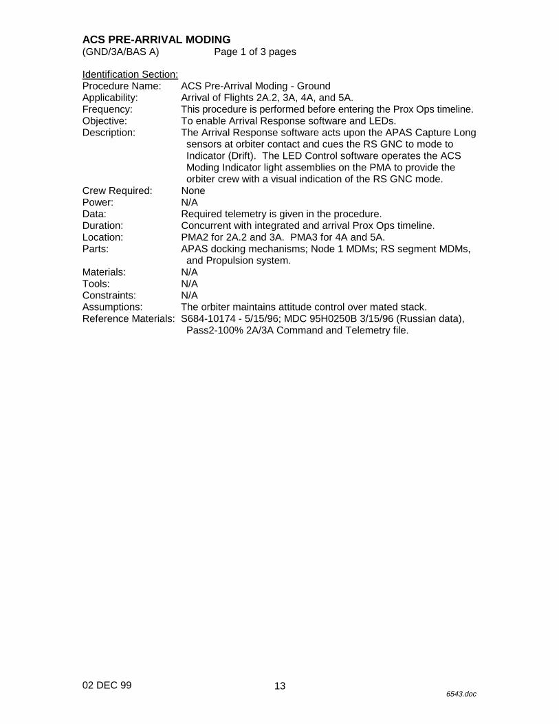
ACS PRE-ARRIVAL MODING(GND/3A/BAS A) Page 1 of 3 pages
02 DEC 996543.doc
Identification Section:Procedure Name: ACS Pre-Arrival Moding - GroundApplicability: Arrival of Flights 2A.2, 3A, 4A, and 5A.Frequency: This procedure is performed before entering the Prox Ops timeline.Objective: To enable Arrival Response software and LEDs.Description: The Arrival Response software acts upon the APAS Capture Long
sensors at orbiter contact and cues the RS GNC to mode toIndicator (Drift). The LED Control software operates the ACSModing Indicator light assemblies on the PMA to provide theorbiter crew with a visual indication of the RS GNC mode.
Crew Required: NonePower: N/AData: Required telemetry is given in the procedure.Duration: Concurrent with integrated and arrival Prox Ops timeline.Location: PMA2 for 2A.2 and 3A. PMA3 for 4A and 5A.Parts: APAS docking mechanisms; Node 1 MDMs; RS segment MDMs,
and Propulsion system.Materials: N/ATools: N/AConstraints: N/AAssumptions: The orbiter maintains attitude control over mated stack.Reference Materials: S684-10174 - 5/15/96; MDC 95H0250B 3/15/96 (Russian data),
Pass2-100% 2A/3A Command and Telemetry file.
13
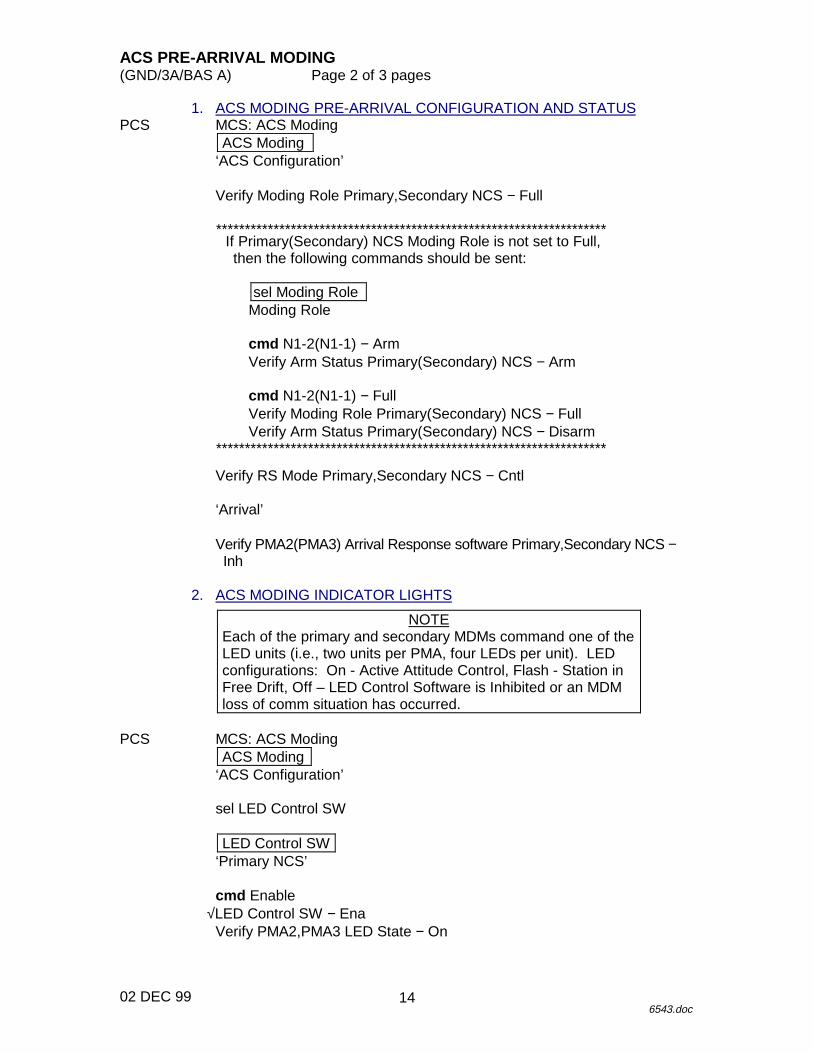
ACS PRE-ARRIVAL MODING(GND/3A/BAS A) Page 2 of 3 pages
02 DEC 996543.doc
1. ACS MODING PRE-ARRIVAL CONFIGURATION AND STATUSPCS MCS: ACS Moding
ACS Moding‘ACS Configuration’
Verify Moding Role Primary,Secondary NCS − Full
********************************************************************If Primary(Secondary) NCS Moding Role is not set to Full,then the following commands should be sent:
sel Moding RoleModing Role
cmd N1-2(N1-1) − ArmVerify Arm Status Primary(Secondary) NCS − Arm
cmd N1-2(N1-1) − FullVerify Moding Role Primary(Secondary) NCS − FullVerify Arm Status Primary(Secondary) NCS − Disarm
********************************************************************
Verify RS Mode Primary,Secondary NCS − Cntl
‘Arrival’
Verify PMA2(PMA3) Arrival Response software Primary,Secondary NCS −Inh
2. ACS MODING INDICATOR LIGHTS
NOTEEach of the primary and secondary MDMs command one of theLED units (i.e., two units per PMA, four LEDs per unit). LEDconfigurations: On - Active Attitude Control, Flash - Station inFree Drift, Off – LED Control Software is Inhibited or an MDMloss of comm situation has occurred.
PCS MCS: ACS ModingACS Moding
‘ACS Configuration’
sel LED Control SW
LED Control SW‘Primary NCS’
cmd Enable√LED Control SW − Ena
Verify PMA2,PMA3 LED State − On
14
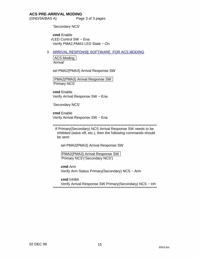
ACS PRE-ARRIVAL MODING(GND/3A/BAS A) Page 3 of 3 pages
02 DEC 996543.doc
‘Secondary NCS’
cmd Enable√LED Control SW − Ena
Verify PMA2,PMA3 LED State − On
3. ARRIVAL RESPONSE SOFTWARE FOR ACS MODING
ACS Moding‘Arrival’
sel PMA2(PMA3) Arrival Response SW
PMA2(PMA3) Arrival Response SW‘Primary NCS’
cmd EnableVerify Arrival Response SW − Ena
‘Secondary NCS’
cmd EnableVerify Arrival Response SW − Ena
**************************************************************************If Primary(Secondary) NCS Arrival Response SW needs to beinhibited (wave off, etc.), then the following commands shouldbe sent:
sel PMA2(PMA3) Arrival Response SW
PMA2(PMA3) Arrival Response SW‘Primary NCS’(‘Secondary NCS’)
cmd ArmVerify Arm Status Primary(Secondary) NCS − Arm
cmd InhibitVerify Arrival Response SW Primary(Secondary) NCS − Inh
**************************************************************************
15

12 JUN 00
This Page Intentionally Blank
16

ACS ARRIVAL MODING(GND/3A/BAS A) Page 1 of 2 pages
02 DEC 996546.doc
Identification Section:Procedure Name: ACS Arrival Moding - GroundApplicability: Arrival of Flights 2A.2, 3A, 4A, and 5A.Frequency: This procedure is performed during the Prox Ops timeline.Objective: To monitor the ACS Moding function during orbiter arrival.Description: The ACS Moding software declares an Orbiter Arrival Event
based on APAS Capture Long sensor signals. The Arrival Eventcues the RS GNC to mode to Indicator (Drift). The ACS Modingindicator lights provide orbiter crew with a visual indication of theRS GNC mode.
Crew Required: NonePower: N/AData: Required telemetry is given in the procedure.Duration: Concurrent with integrated and arrival Prox Ops timeline.Location: PMA2 for 2A.2 and 3A. PMA3 for 4A and 5A.Parts: APAS docking mechanisms; Node 1 MDMs; RS segment MDMs,
and Propulsion system.Materials: N/ATools: N/AConstraints: N/AAssumptions: The orbiter maintains attitude control over mated stack.Reference Materials: S684-10174 - 5/15/96; MDC 95H0250B 3/15/96 (Russian data),
Pass2-100% 2A/3A Command and Telemetry file.
17
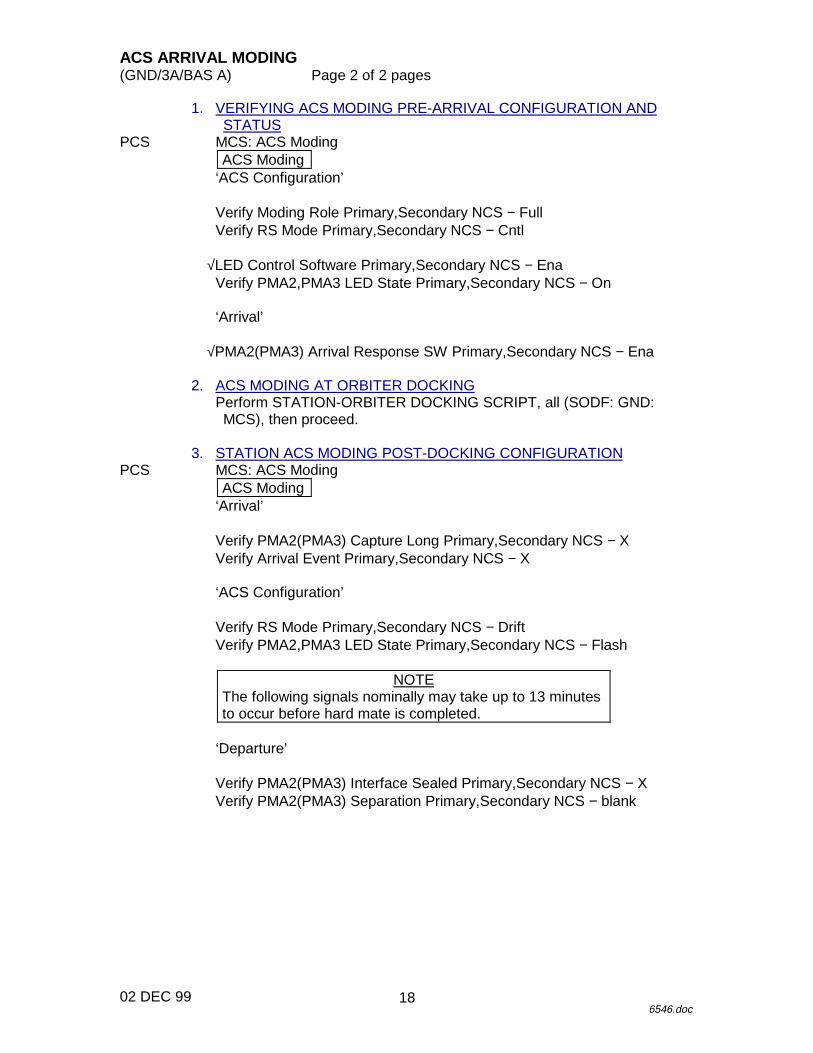
ACS ARRIVAL MODING(GND/3A/BAS A) Page 2 of 2 pages
02 DEC 996546.doc
1. VERIFYING ACS MODING PRE-ARRIVAL CONFIGURATION ANDSTATUS
PCS MCS: ACS ModingACS Moding
‘ACS Configuration’
Verify Moding Role Primary,Secondary NCS − FullVerify RS Mode Primary,Secondary NCS − Cntl
√LED Control Software Primary,Secondary NCS − EnaVerify PMA2,PMA3 LED State Primary,Secondary NCS − On
‘Arrival’
√PMA2(PMA3) Arrival Response SW Primary,Secondary NCS − Ena
2. ACS MODING AT ORBITER DOCKINGPerform STATION-ORBITER DOCKING SCRIPT, all (SODF: GND:MCS), then proceed.
3. STATION ACS MODING POST-DOCKING CONFIGURATIONPCS MCS: ACS Moding
ACS Moding‘Arrival’
Verify PMA2(PMA3) Capture Long Primary,Secondary NCS − XVerify Arrival Event Primary,Secondary NCS − X
‘ACS Configuration’
Verify RS Mode Primary,Secondary NCS − DriftVerify PMA2,PMA3 LED State Primary,Secondary NCS − Flash
NOTEThe following signals nominally may take up to 13 minutesto occur before hard mate is completed.
‘Departure’
Verify PMA2(PMA3) Interface Sealed Primary,Secondary NCS − XVerify PMA2(PMA3) Separation Primary,Secondary NCS − blank
18
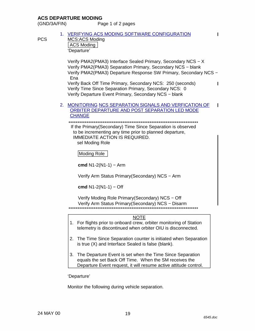
ACS DEPARTURE MODING(GND/3A/FIN) Page 1 of 2 pages
24 MAY 006545.doc
1. VERIFYING ACS MODING SOFTWARE CONFIGURATIONPCS MCS:ACS Moding
ACS Moding‘Departure’
Verify PMA2(PMA3) Interface Sealed Primary, Secondary NCS − XVerify PMA2(PMA3) Separation Primary, Secondary NCS − blankVerify PMA2(PMA3) Departure Response SW Primary, Secondary NCS −Ena
Verify Back Off Time Primary, Secondary NCS: 250 (seconds)Verify Time Since Separation Primary, Secondary NCS: 0Verify Departure Event Primary, Secondary NCS − blank
2. MONITORING NCS SEPARATION SIGNALS AND VERFICATION OFORBITER DEPARTURE AND POST SEPARATION LED MODECHANGE
************************************************************************If the Primary(Secondary) Time Since Separation is observedto be incrementing any time prior to planned departure,IMMEDIATE ACTION IS REQUIRED.
sel Moding Role
Moding Role
cmd N1-2(N1-1) − Arm
Verify Arm Status Primary(Secondary) NCS − Arm
cmd N1-2(N1-1) − Off
Verify Moding Role Primary(Secondary) NCS − OffVerify Arm Status Primary(Secondary) NCS − Disarm
************************************************************************
NOTE1. For flights prior to onboard crew, orbiter monitoring of Station
telemetry is discontinued when orbiter OIU is disconnected.
2. The Time Since Separation counter is initiated when Separationis true (X) and Interface Sealed is false (blank).
3. The Departure Event is set when the Time Since Separationequals the set Back Off Time. When the SM receives theDeparture Event request, it will resume active attitude control.
‘Departure’
Monitor the following during vehicle separation.
19
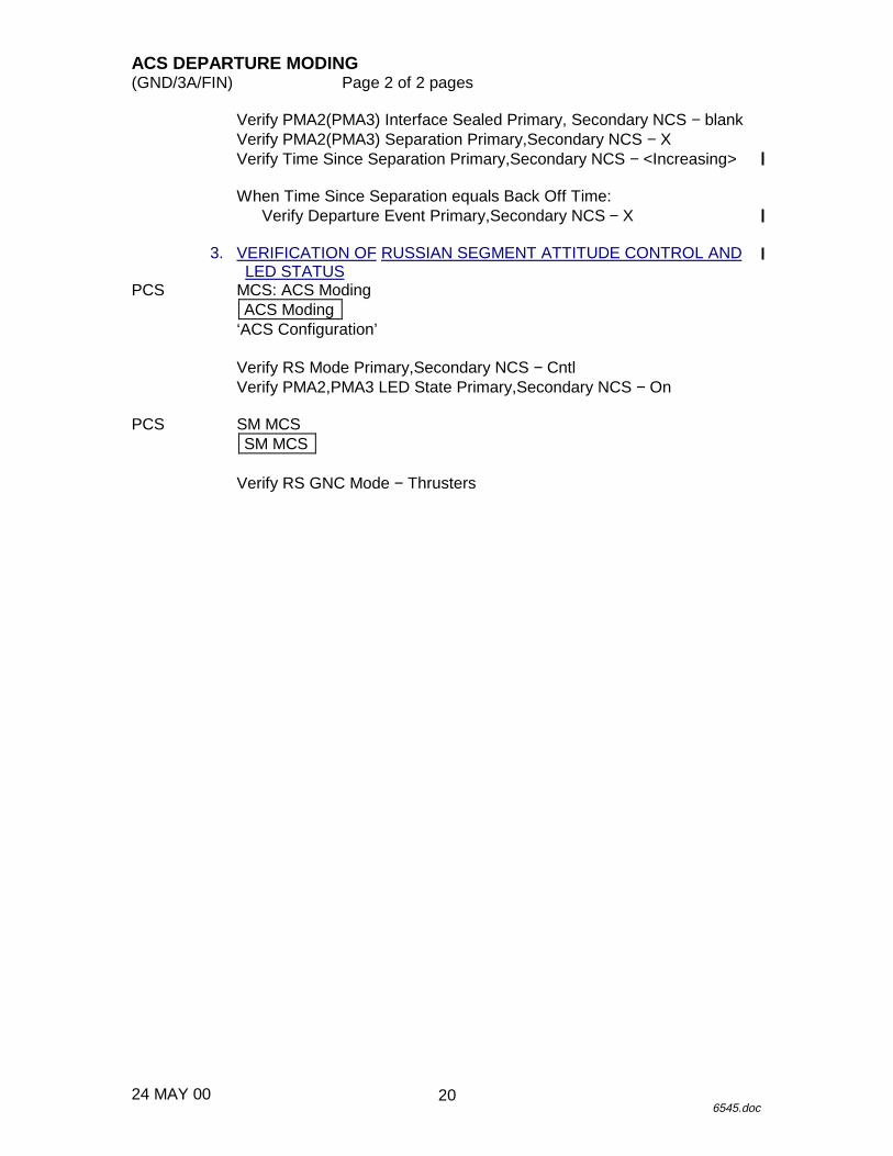
ACS DEPARTURE MODING(GND/3A/FIN) Page 2 of 2 pages
24 MAY 006545.doc
Verify PMA2(PMA3) Interface Sealed Primary, Secondary NCS − blankVerify PMA2(PMA3) Separation Primary,Secondary NCS − XVerify Time Since Separation Primary,Secondary NCS − <Increasing>
When Time Since Separation equals Back Off Time:Verify Departure Event Primary,Secondary NCS − X
3. VERIFICATION OF RUSSIAN SEGMENT ATTITUDE CONTROL ANDLED STATUS
PCS MCS: ACS ModingACS Moding
‘ACS Configuration’
Verify RS Mode Primary,Secondary NCS − CntlVerify PMA2,PMA3 LED State Primary,Secondary NCS − On
PCS SM MCSSM MCS
Verify RS GNC Mode − Thrusters
20
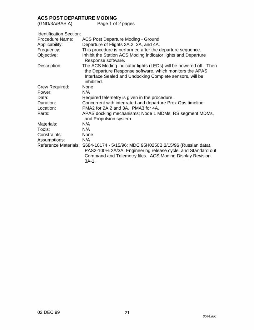
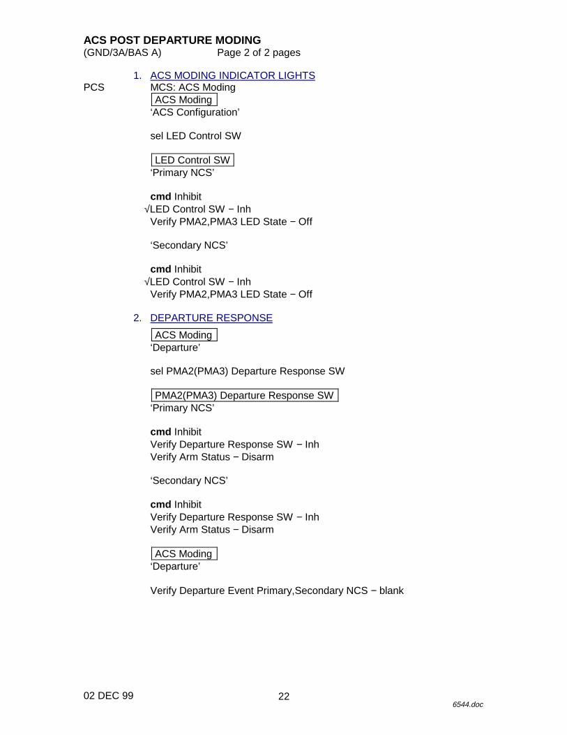
ACS POST DEPARTURE MODING(GND/3A/BAS A) Page 1 of 2 pages
02 DEC 996544.doc
Identification Section:Procedure Name: ACS Post Departure Moding - GroundApplicability: Departure of Flights 2A.2, 3A, and 4A.Frequency: This procedure is performed after the departure sequence.Objective: Inhibit the Station ACS Moding indicator lights and Departure
Response software.Description: The ACS Moding indicator lights (LEDs) will be powered off. Then
the Departure Response software, which monitors the APASInterface Sealed and Undocking Complete sensors, will beinhibited.
Crew Required: NonePower: N/AData: Required telemetry is given in the procedure.Duration: Concurrent with integrated and departure Prox Ops timeline.Location: PMA2 for 2A.2 and 3A. PMA3 for 4A.Parts: APAS docking mechanisms; Node 1 MDMs; RS segment MDMs,
and Propulsion system.Materials: N/ATools: N/AConstraints: NoneAssumptions: N/AReference Materials: S684-10174 - 5/15/96; MDC 95H0250B 3/15/96 (Russian data),
PAS2-100% 2A/3A, Engineering release cycle, and Standard outCommand and Telemetry files. ACS Moding Display Revision3A-1.
21
ACS POST DEPARTURE MODING(GND/3A/BAS A) Page 2 of 2 pages
02 DEC 996544.doc
1. ACS MODING INDICATOR LIGHTSPCS MCS: ACS Moding
ACS Moding‘ACS Configuration’
sel LED Control SW
LED Control SW‘Primary NCS’
cmd Inhibit√LED Control SW − Inh
Verify PMA2,PMA3 LED State − Off
‘Secondary NCS’
cmd Inhibit√LED Control SW − Inh
Verify PMA2,PMA3 LED State − Off
2. DEPARTURE RESPONSE
ACS Moding‘Departure’
sel PMA2(PMA3) Departure Response SW
PMA2(PMA3) Departure Response SW‘Primary NCS’
cmd InhibitVerify Departure Response SW − InhVerify Arm Status − Disarm
‘Secondary NCS’
cmd InhibitVerify Departure Response SW − InhVerify Arm Status − Disarm
ACS Moding‘Departure’
Verify Departure Event Primary,Secondary NCS − blank
22

12 JUN 00
S&M PROCEDURES
S&M
23

12 JUN 00
This Page Intentionally Blank
S&M
24
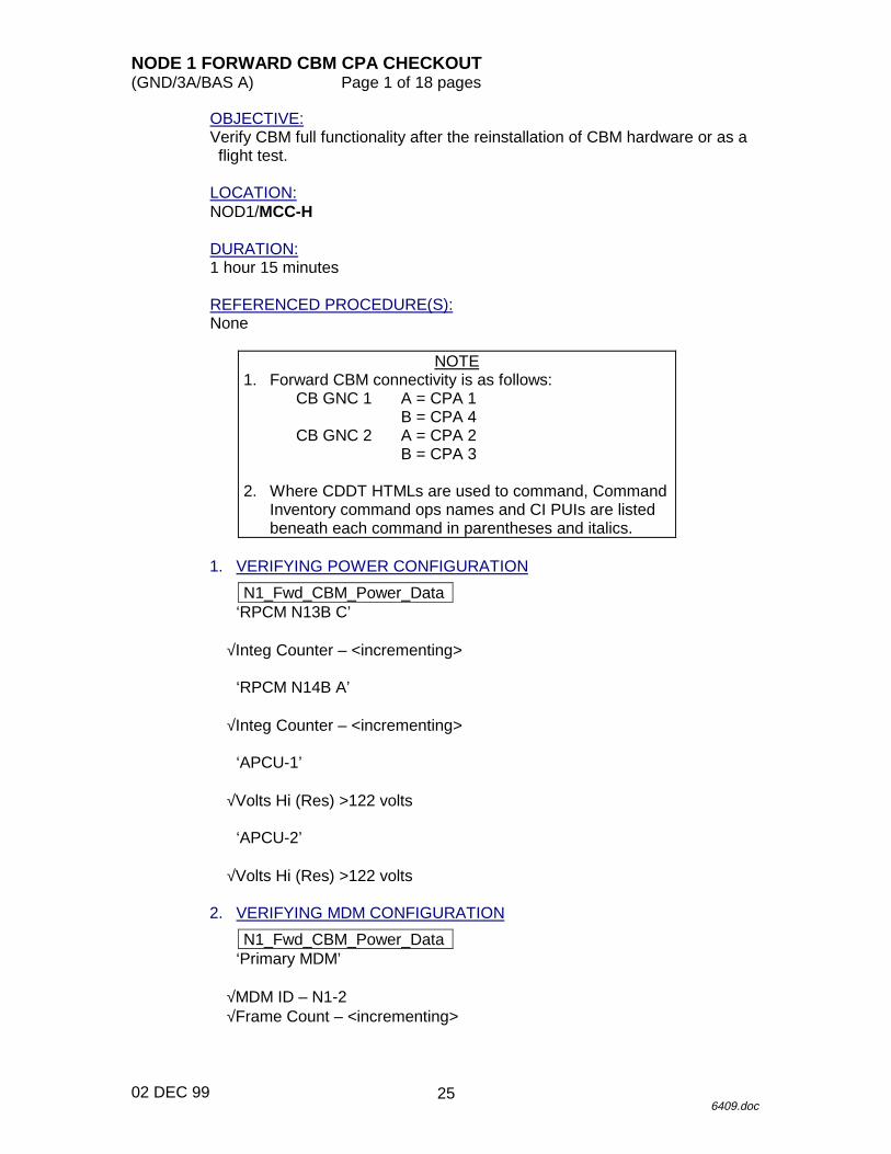
NODE 1 FORWARD CBM CPA CHECKOUT(GND/3A/BAS A) Page 1 of 18 pages
02 DEC 996409.doc
OBJECTIVE:Verify CBM full functionality after the reinstallation of CBM hardware or as aflight test.
LOCATION:NOD1/MCC-H
DURATION:1 hour 15 minutes
REFERENCED PROCEDURE(S):None
NOTE1. Forward CBM connectivity is as follows:
CB GNC 1 A = CPA 1B = CPA 4
CB GNC 2 A = CPA 2B = CPA 3
2. Where CDDT HTMLs are used to command, CommandInventory command ops names and CI PUIs are listedbeneath each command in parentheses and italics.
1. VERIFYING POWER CONFIGURATION
N1_Fwd_CBM_Power_Data‘RPCM N13B C’
√Integ Counter – <incrementing>
‘RPCM N14B A’
√Integ Counter – <incrementing>
‘APCU-1’
√Volts Hi (Res) >122 volts
‘APCU-2’
√Volts Hi (Res) >122 volts
2. VERIFYING MDM CONFIGURATION
N1_Fwd_CBM_Power_Data‘Primary MDM’
√MDM ID – N1-2√Frame Count – <incrementing>
25
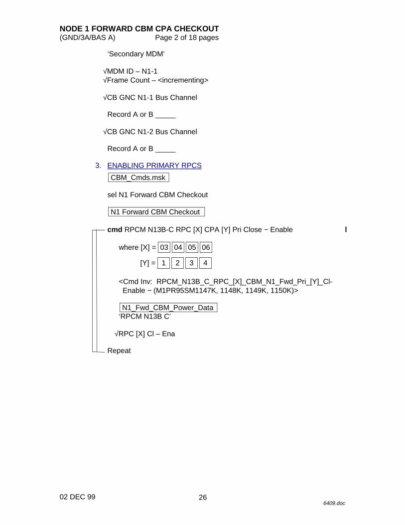
NODE 1 FORWARD CBM CPA CHECKOUT(GND/3A/BAS A) Page 2 of 18 pages
02 DEC 996409.doc
‘Secondary MDM’
√MDM ID – N1-1√Frame Count – <incrementing>
√CB GNC N1-1 Bus Channel
Record A or B _____
√CB GNC N1-2 Bus Channel
Record A or B _____
3. ENABLING PRIMARY RPCS
CBM_Cmds.msk
sel N1 Forward CBM Checkout
N1 Forward CBM Checkout
cmd RPCM N13B-C RPC [X] CPA [Y] Pri Close − Enable
where [X] = 06050403
[Y] = 4321
<Cmd Inv: RPCM_N13B_C_RPC_[X]_CBM_N1_Fwd_Pri_[Y]_Cl-Enable − (M1PR95SM1147K, 1148K, 1149K, 1150K)>
N1_Fwd_CBM_Power_Data‘RPCM N13B C’
√RPC [X] Cl – Ena
Repeat
26
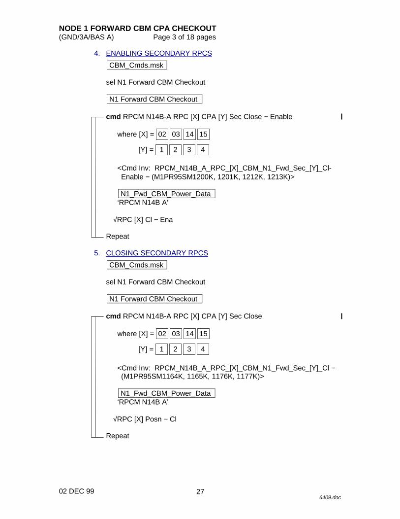
NODE 1 FORWARD CBM CPA CHECKOUT(GND/3A/BAS A) Page 3 of 18 pages
02 DEC 996409.doc
4. ENABLING SECONDARY RPCS
CBM_Cmds.msk
sel N1 Forward CBM Checkout
N1 Forward CBM Checkout
cmd RPCM N14B-A RPC [X] CPA [Y] Sec Close − Enable
where [X] = 15140302
[Y] = 4321
<Cmd Inv: RPCM_N14B_A_RPC_[X]_CBM_N1_Fwd_Sec_[Y]_Cl-Enable − (M1PR95SM1200K, 1201K, 1212K, 1213K)>
N1_Fwd_CBM_Power_Data‘RPCM N14B A’
√RPC [X] Cl − Ena
Repeat
5. CLOSING SECONDARY RPCS
CBM_Cmds.msk
sel N1 Forward CBM Checkout
N1 Forward CBM Checkout
cmd RPCM N14B-A RPC [X] CPA [Y] Sec Close
where [X] = 15140302
[Y] = 4321
<Cmd Inv: RPCM_N14B_A_RPC_[X]_CBM_N1_Fwd_Sec_[Y]_Cl −(M1PR95SM1164K, 1165K, 1176K, 1177K)>
N1_Fwd_CBM_Power_Data‘RPCM N14B A’
√RPC [X] Posn − Cl
Repeat
27
NODE 1 FORWARD CBM CPA CHECKOUT(GND/3A/BAS A) Page 4 of 18 pages
02 DEC 996409.doc
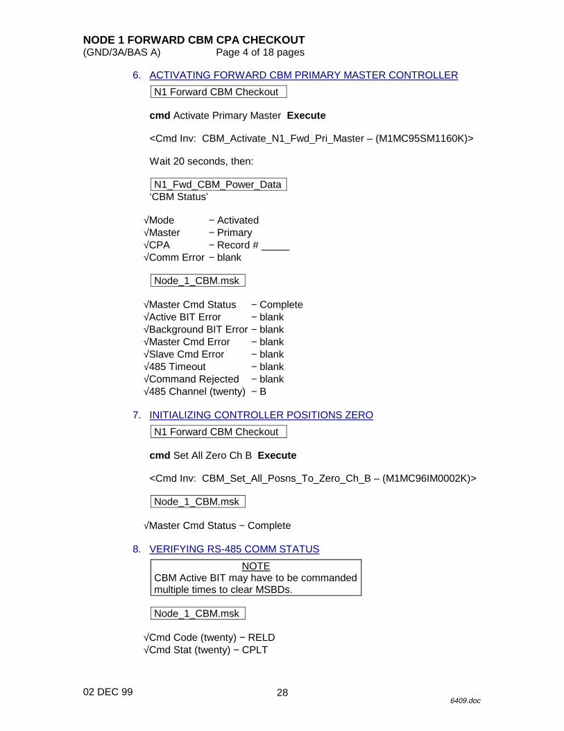
6. ACTIVATING FORWARD CBM PRIMARY MASTER CONTROLLER
N1 Forward CBM Checkout
cmd Activate Primary Master Execute
<Cmd Inv: CBM_Activate_N1_Fwd_Pri_Master – (M1MC95SM1160K)>
Wait 20 seconds, then:
N1_Fwd_CBM_Power_Data‘CBM Status’
√Mode − Activated√Master − Primary√CPA − Record # _____√Comm Error − blank
Node_1_CBM.msk
√Master Cmd Status − Complete√Active BIT Error − blank√Background BIT Error − blank√Master Cmd Error − blank√Slave Cmd Error − blank√485 Timeout − blank√Command Rejected − blank√485 Channel (twenty) − B
7. INITIALIZING CONTROLLER POSITIONS ZERO
N1 Forward CBM Checkout
cmd Set All Zero Ch B Execute
<Cmd Inv: CBM_Set_All_Posns_To_Zero_Ch_B – (M1MC96IM0002K)>
Node_1_CBM.msk
√Master Cmd Status − Complete
8. VERIFYING RS-485 COMM STATUS
NOTECBM Active BIT may have to be commandedmultiple times to clear MSBDs.
Node_1_CBM.msk
√Cmd Code (twenty) − RELD√Cmd Stat (twenty) − CPLT
28
NODE 1 FORWARD CBM CPA CHECKOUT(GND/3A/BAS A) Page 5 of 18 pages
02 DEC 996409.doc
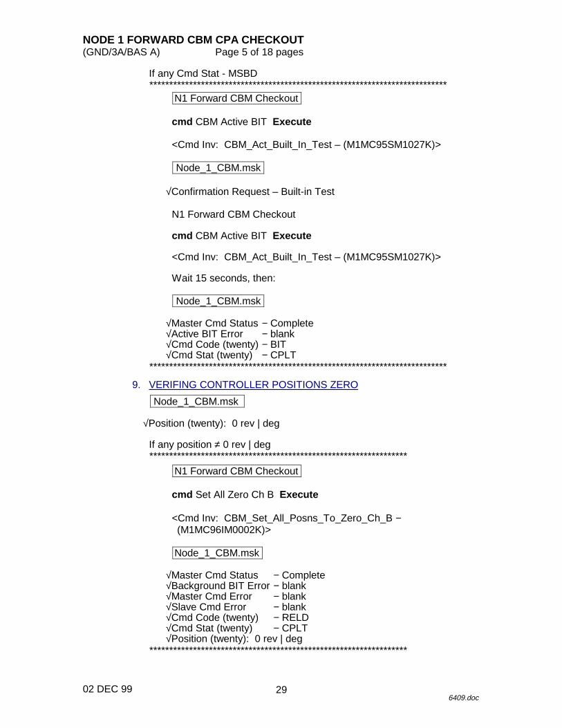
If any Cmd Stat - MSBD***************************************************************************
N1 Forward CBM Checkout
cmd CBM Active BIT Execute
<Cmd Inv: CBM_Act_Built_In_Test – (M1MC95SM1027K)>
Node_1_CBM.msk
√Confirmation Request – Built-in Test
N1 Forward CBM Checkout
cmd CBM Active BIT Execute
<Cmd Inv: CBM_Act_Built_In_Test – (M1MC95SM1027K)>
Wait 15 seconds, then:
Node_1_CBM.msk
√Master Cmd Status − Complete√Active BIT Error − blank√Cmd Code (twenty) − BIT√Cmd Stat (twenty) − CPLT
***************************************************************************
9. VERIFING CONTROLLER POSITIONS ZERO
Node_1_CBM.msk
√Position (twenty): 0 rev | deg
If any position ≠ 0 rev | deg*****************************************************************
N1 Forward CBM Checkout
cmd Set All Zero Ch B Execute
<Cmd Inv: CBM_Set_All_Posns_To_Zero_Ch_B −(M1MC96IM0002K)>
Node_1_CBM.msk
√Master Cmd Status − Complete√Background BIT Error − blank√Master Cmd Error − blank√Slave Cmd Error − blank√Cmd Code (twenty) − RELD√Cmd Stat (twenty) − CPLT√Position (twenty): 0 rev | deg
*****************************************************************
29
NODE 1 FORWARD CBM CPA CHECKOUT(GND/3A/BAS A) Page 6 of 18 pages
02 DEC 996409.doc
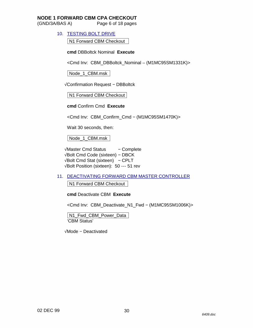
10. TESTING BOLT DRIVE
N1 Forward CBM Checkout
cmd DBBoltck Nominal Execute
<Cmd Inv: CBM_DBBoltck_Nominal – (M1MC95SM1331K)>
Node_1_CBM.msk
√Confirmation Request − DBBoltck
N1 Forward CBM Checkout
cmd Confirm Cmd Execute
<Cmd Inv: CBM_Confirm_Cmd − (M1MC95SM1470K)>
Wait 30 seconds, then:
Node_1_CBM.msk
√Master Cmd Status − Complete√Bolt Cmd Code (sixteen) − DBCK√Bolt Cmd Stat (sixteen) − CPLT√Bolt Position (sixteen): 50 --- 51 rev
11. DEACTIVATING FORWARD CBM MASTER CONTROLLER
N1 Forward CBM Checkout
cmd Deactivate CBM Execute
<Cmd Inv: CBM_Deactivate_N1_Fwd − (M1MC95SM1006K)>
N1_Fwd_CBM_Power_Data‘CBM Status’
√Mode − Deactivated
30
NODE 1 FORWARD CBM CPA CHECKOUT(GND/3A/BAS A) Page 7 of 18 pages
02 DEC 996409.doc
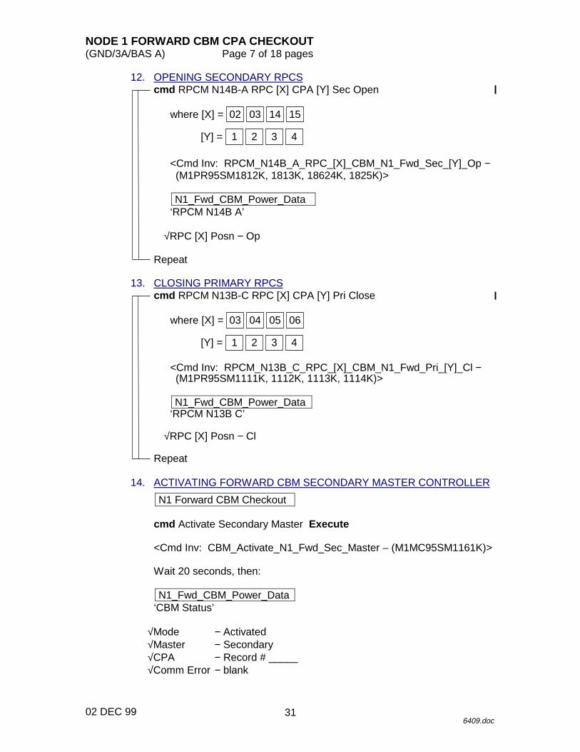
12. OPENING SECONDARY RPCScmd RPCM N14B-A RPC [X] CPA [Y] Sec Open
where [X] = 15140302
[Y] = 4321
<Cmd Inv: RPCM_N14B_A_RPC_[X]_CBM_N1_Fwd_Sec_[Y]_Op −(M1PR95SM1812K, 1813K, 18624K, 1825K)>
N1_Fwd_CBM_Power_Data‘RPCM N14B A’
√RPC [X] Posn − Op
Repeat
13. CLOSING PRIMARY RPCScmd RPCM N13B-C RPC [X] CPA [Y] Pri Close
where [X] = 06050403
[Y] = 4321
<Cmd Inv: RPCM_N13B_C_RPC_[X]_CBM_N1_Fwd_Pri_[Y]_Cl −(M1PR95SM1111K, 1112K, 1113K, 1114K)>
N1_Fwd_CBM_Power_Data‘RPCM N13B C’
√RPC [X] Posn − Cl
Repeat
14. ACTIVATING FORWARD CBM SECONDARY MASTER CONTROLLER
N1 Forward CBM Checkout
cmd Activate Secondary Master Execute
<Cmd Inv: CBM_Activate_N1_Fwd_Sec_Master – (M1MC95SM1161K)>
Wait 20 seconds, then:
N1_Fwd_CBM_Power_Data‘CBM Status’
√Mode − Activated√Master − Secondary√CPA − Record # _____√Comm Error − blank
31
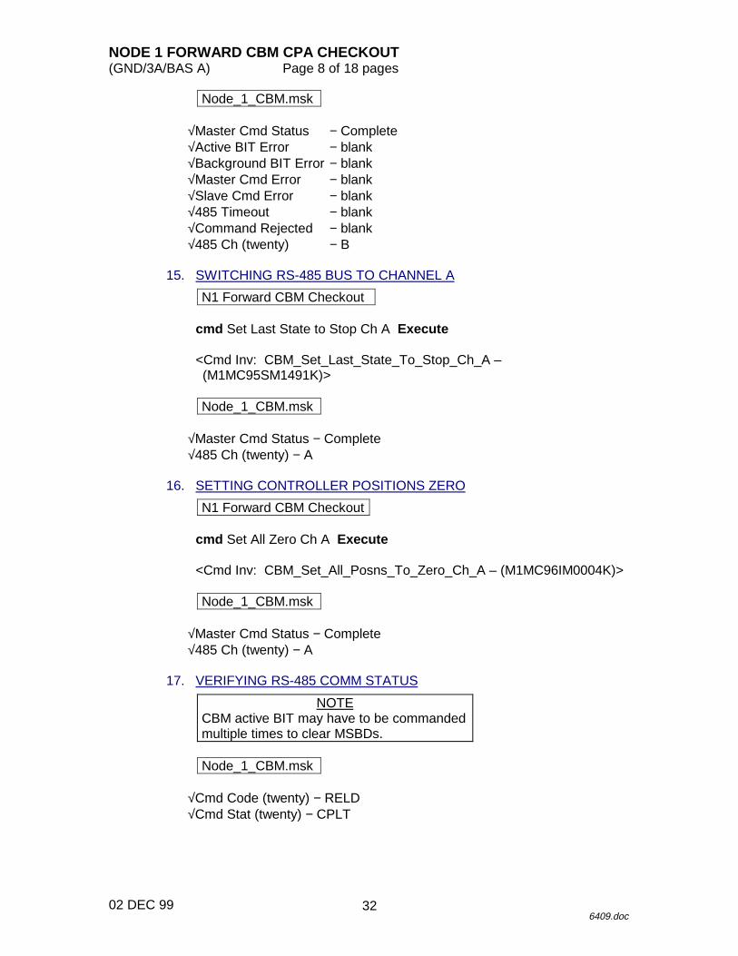
NODE 1 FORWARD CBM CPA CHECKOUT(GND/3A/BAS A) Page 8 of 18 pages
02 DEC 996409.doc
Node_1_CBM.msk
√Master Cmd Status − Complete√Active BIT Error − blank√Background BIT Error − blank√Master Cmd Error − blank√Slave Cmd Error − blank√485 Timeout − blank√Command Rejected − blank√485 Ch (twenty) − B
15. SWITCHING RS-485 BUS TO CHANNEL A
N1 Forward CBM Checkout
cmd Set Last State to Stop Ch A Execute
<Cmd Inv: CBM_Set_Last_State_To_Stop_Ch_A –(M1MC95SM1491K)>
Node_1_CBM.msk
√Master Cmd Status − Complete√485 Ch (twenty) − A
16. SETTING CONTROLLER POSITIONS ZERO
N1 Forward CBM Checkout
cmd Set All Zero Ch A Execute
<Cmd Inv: CBM_Set_All_Posns_To_Zero_Ch_A – (M1MC96IM0004K)>
Node_1_CBM.msk
√Master Cmd Status − Complete√485 Ch (twenty) − A
17. VERIFYING RS-485 COMM STATUS
NOTECBM active BIT may have to be commandedmultiple times to clear MSBDs.
Node_1_CBM.msk
√Cmd Code (twenty) − RELD√Cmd Stat (twenty) − CPLT
32
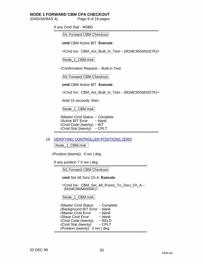
NODE 1 FORWARD CBM CPA CHECKOUT(GND/3A/BAS A) Page 9 of 18 pages
02 DEC 996409.doc
If any Cmd Stat - MSBD*************************************************************************
N1 Forward CBM Checkout
cmd CBM Active BIT Execute
<Cmd Inv: CBM_Act_Built_In_Test – (M1MC95SM1027K)>
Node_1_CBM.msk
√Confirmation Request – Built-in Test
N1 Forward CBM Checkout
cmd CBM Active BIT Execute
<Cmd Inv: CBM_Act_Built_In_Test – (M1MC95SM1027K)>
Wait 15 seconds, then:
Node_1_CBM.msk
√Master Cmd Status − Complete√Active BIT Error − blank√Cmd Code (twenty) − BIT√Cmd Stat (twenty) − CPLT
*************************************************************************
18. VERIFYING CONTROLLER POSITIONS ZERO
Node_1_CBM.msk
√Position (twenty): 0 rev | deg
If any position ? 0 rev | deg*****************************************************************
N1 Forward CBM Checkout
cmd Set All Zero Ch A Execute
<Cmd Inv: CBM_Set_All_Posns_To_Zero_Ch_A –(M1MC96IM0004K)>
Node_1_CBM.msk
√Master Cmd Status − Complete√Background BIT Error − blank√Master Cmd Error − blank√Slave Cmd Error − blank√Cmd Code (twenty) − RELD√Cmd Stat (twenty) − CPLT√Position (twenty): 0 rev | deg
*****************************************************************
33
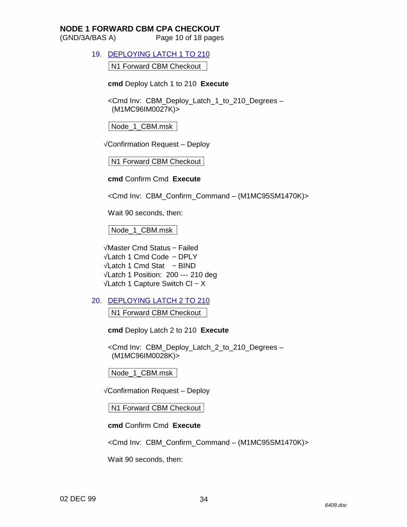
NODE 1 FORWARD CBM CPA CHECKOUT(GND/3A/BAS A) Page 10 of 18 pages
02 DEC 996409.doc
19. DEPLOYING LATCH 1 TO 210
N1 Forward CBM Checkout
cmd Deploy Latch 1 to 210 Execute
<Cmd Inv: CBM_Deploy_Latch_1_to_210_Degrees –(M1MC96IM0027K)>
Node_1_CBM.msk
√Confirmation Request – Deploy
N1 Forward CBM Checkout
cmd Confirm Cmd Execute
<Cmd Inv: CBM_Confirm_Command – (M1MC95SM1470K)>
Wait 90 seconds, then:
Node_1_CBM.msk
√Master Cmd Status − Failed√Latch 1 Cmd Code − DPLY√Latch 1 Cmd Stat − BIND√Latch 1 Position: 200 --- 210 deg√Latch 1 Capture Switch Cl − X
20. DEPLOYING LATCH 2 TO 210
N1 Forward CBM Checkout
cmd Deploy Latch 2 to 210 Execute
<Cmd Inv: CBM_Deploy_Latch_2_to_210_Degrees –(M1MC96IM0028K)>
Node_1_CBM.msk
√Confirmation Request – Deploy
N1 Forward CBM Checkout
cmd Confirm Cmd Execute
<Cmd Inv: CBM_Confirm_Command – (M1MC95SM1470K)>
Wait 90 seconds, then:
34
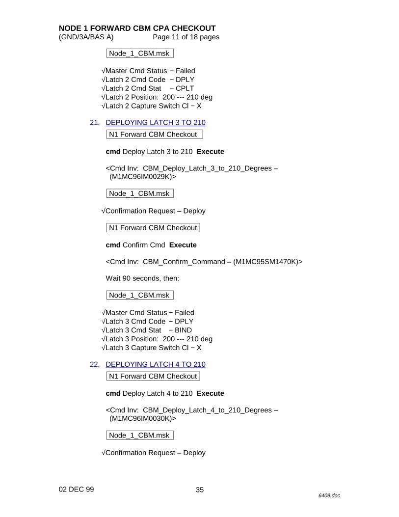
NODE 1 FORWARD CBM CPA CHECKOUT(GND/3A/BAS A) Page 11 of 18 pages
02 DEC 996409.doc
Node_1_CBM.msk
√Master Cmd Status − Failed√Latch 2 Cmd Code − DPLY√Latch 2 Cmd Stat − CPLT√Latch 2 Position: 200 --- 210 deg√Latch 2 Capture Switch Cl − X
21. DEPLOYING LATCH 3 TO 210
N1 Forward CBM Checkout
cmd Deploy Latch 3 to 210 Execute
<Cmd Inv: CBM_Deploy_Latch_3_to_210_Degrees –(M1MC96IM0029K)>
Node_1_CBM.msk
√Confirmation Request – Deploy
N1 Forward CBM Checkout
cmd Confirm Cmd Execute
<Cmd Inv: CBM_Confirm_Command – (M1MC95SM1470K)>
Wait 90 seconds, then:
Node_1_CBM.msk
√Master Cmd Status − Failed√Latch 3 Cmd Code − DPLY√Latch 3 Cmd Stat − BIND√Latch 3 Position: 200 --- 210 deg√Latch 3 Capture Switch Cl − X
22. DEPLOYING LATCH 4 TO 210
N1 Forward CBM Checkout
cmd Deploy Latch 4 to 210 Execute
<Cmd Inv: CBM_Deploy_Latch_4_to_210_Degrees –(M1MC96IM0030K)>
Node_1_CBM.msk
√Confirmation Request – Deploy
35
NODE 1 FORWARD CBM CPA CHECKOUT(GND/3A/BAS A) Page 12 of 18 pages
02 DEC 996409.doc
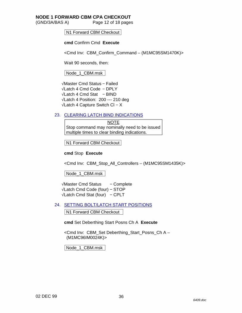
N1 Forward CBM Checkout
cmd Confirm Cmd Execute
<Cmd Inv: CBM_Confirm_Command – (M1MC95SM1470K)>
Wait 90 seconds, then:
Node_1_CBM.msk
√Master Cmd Status − Failed√Latch 4 Cmd Code − DPLY√Latch 4 Cmd Stat − BIND√Latch 4 Position: 200 --- 210 deg√Latch 4 Capture Switch Cl − X
23. CLEARING LATCH BIND INDICATIONS
NOTEStop command may nominally need to be issuedmultiple times to clear binding indications.
N1 Forward CBM Checkout
cmd Stop Execute
<Cmd Inv: CBM_Stop_All_Controllers – (M1MC95SM1435K)>
Node_1_CBM.msk
√Master Cmd Status − Complete√Latch Cmd Code (four) − STOP√Latch Cmd Stat (four) − CPLT
24. SETTING BOLT/LATCH START POSITIONS
N1 Forward CBM Checkout
cmd Set Deberthing Start Posns Ch A Execute
<Cmd Inv: CBM_Set Deberthing_Start_Posns_Ch A –(M1MC96IM0024K)>
Node_1_CBM.msk
36
NODE 1 FORWARD CBM CPA CHECKOUT(GND/3A/BAS A) Page 13 of 18 pages
02 DEC 996409.doc
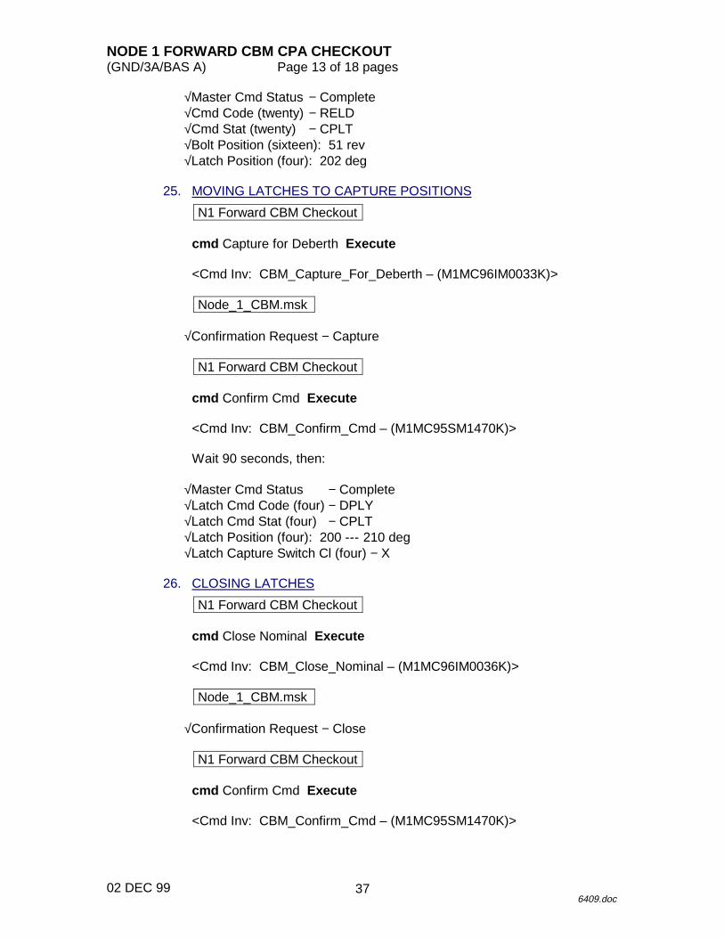
√Master Cmd Status − Complete√Cmd Code (twenty) − RELD√Cmd Stat (twenty) − CPLT√Bolt Position (sixteen): 51 rev√Latch Position (four): 202 deg
25. MOVING LATCHES TO CAPTURE POSITIONS
N1 Forward CBM Checkout
cmd Capture for Deberth Execute
<Cmd Inv: CBM_Capture_For_Deberth – (M1MC96IM0033K)>
Node_1_CBM.msk
√Confirmation Request − Capture
N1 Forward CBM Checkout
cmd Confirm Cmd Execute
<Cmd Inv: CBM_Confirm_Cmd – (M1MC95SM1470K)>
Wait 90 seconds, then:
√Master Cmd Status − Complete√Latch Cmd Code (four) − DPLY√Latch Cmd Stat (four) − CPLT√Latch Position (four): 200 --- 210 deg√Latch Capture Switch Cl (four) − X
26. CLOSING LATCHES
N1 Forward CBM Checkout
cmd Close Nominal Execute
<Cmd Inv: CBM_Close_Nominal – (M1MC96IM0036K)>
Node_1_CBM.msk
√Confirmation Request − Close
N1 Forward CBM Checkout
cmd Confirm Cmd Execute
<Cmd Inv: CBM_Confirm_Cmd – (M1MC95SM1470K)>
37
NODE 1 FORWARD CBM CPA CHECKOUT(GND/3A/BAS A) Page 14 of 18 pages
02 DEC 996409.doc
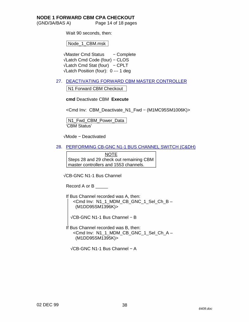
Wait 90 seconds, then:
Node_1_CBM.msk
√Master Cmd Status − Complete√Latch Cmd Code (four) − CLOS√Latch Cmd Stat (four) − CPLT√Latch Position (four): 0 --- 1 deg
27. DEACTIVATING FORWARD CBM MASTER CONTROLLER
N1 Forward CBM Checkout
cmd Deactivate CBM Execute
<Cmd Inv: CBM_Deactivate_N1_Fwd − (M1MC95SM1006K)>
N1_Fwd_CBM_Power_Data‘CBM Status’
√Mode − Deactivated
28. PERFORMING CB-GNC N1-1 BUS CHANNEL SWITCH (C&DH)
NOTESteps 28 and 29 check out remaining CBMmaster controllers and 1553 channels.
√CB-GNC N1-1 Bus Channel
Record A or B _____
If Bus Channel recorded was A, then:<Cmd Inv: N1_1_MDM_CB_GNC_1_Sel_Ch_B –(M1DD95SM1396K)>
√CB-GNC N1-1 Bus Channel − B
If Bus Channel recorded was B, then:<Cmd Inv: N1_1_MDM_CB_GNC_1_Sel_Ch_A –(M1DD95SM1395K)>
√CB-GNC N1-1 Bus Channel − A
38
NODE 1 FORWARD CBM CPA CHECKOUT(GND/3A/BAS A) Page 15 of 18 pages
02 DEC 996409.doc
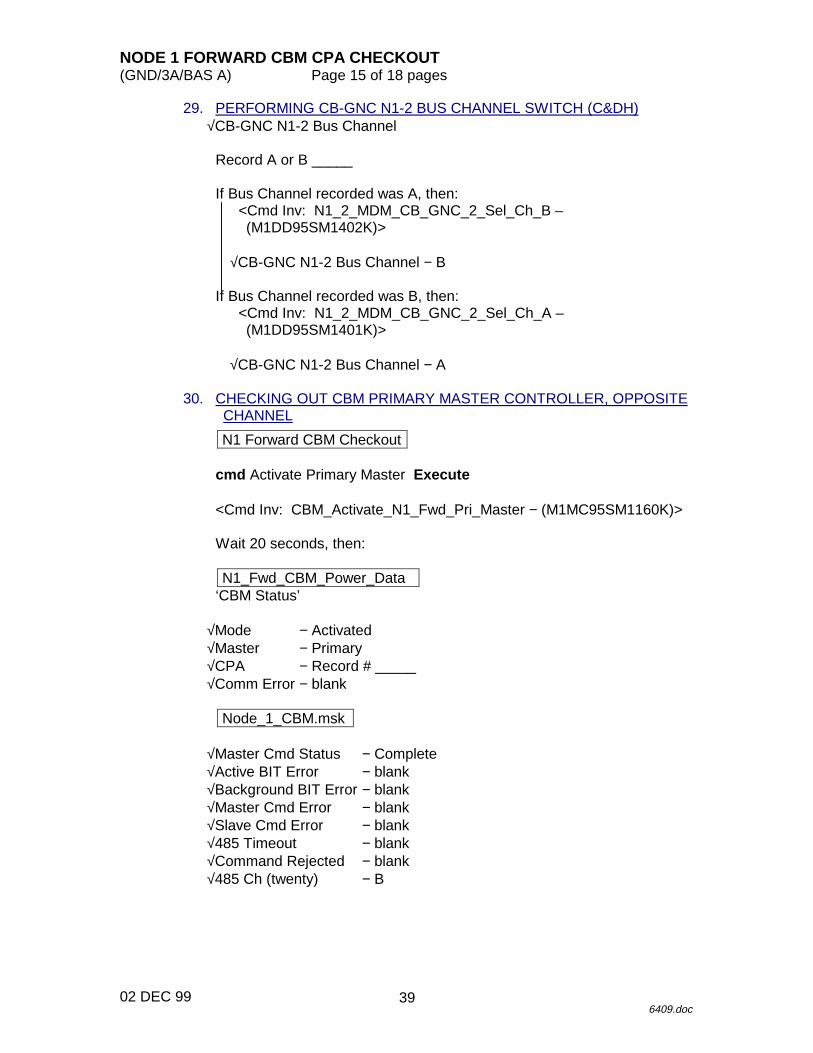
29. PERFORMING CB-GNC N1-2 BUS CHANNEL SWITCH (C&DH)√CB-GNC N1-2 Bus Channel
Record A or B _____
If Bus Channel recorded was A, then:<Cmd Inv: N1_2_MDM_CB_GNC_2_Sel_Ch_B –(M1DD95SM1402K)>
√CB-GNC N1-2 Bus Channel − B
If Bus Channel recorded was B, then:<Cmd Inv: N1_2_MDM_CB_GNC_2_Sel_Ch_A –(M1DD95SM1401K)>
√CB-GNC N1-2 Bus Channel − A
30. CHECKING OUT CBM PRIMARY MASTER CONTROLLER, OPPOSITECHANNEL
N1 Forward CBM Checkout
cmd Activate Primary Master Execute
<Cmd Inv: CBM_Activate_N1_Fwd_Pri_Master − (M1MC95SM1160K)>
Wait 20 seconds, then:
N1_Fwd_CBM_Power_Data‘CBM Status’
√Mode − Activated√Master − Primary√CPA − Record # _____√Comm Error − blank
Node_1_CBM.msk
√Master Cmd Status − Complete√Active BIT Error − blank√Background BIT Error − blank√Master Cmd Error − blank√Slave Cmd Error − blank√485 Timeout − blank√Command Rejected − blank√485 Ch (twenty) − B
39
NODE 1 FORWARD CBM CPA CHECKOUT(GND/3A/BAS A) Page 16 of 18 pages
02 DEC 996409.doc
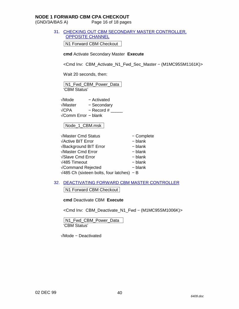
31. CHECKING OUT CBM SECONDARY MASTER CONTROLLER,OPPOSITE CHANNEL
N1 Forward CBM Checkout
cmd Activate Secondary Master Execute
<Cmd Inv: CBM_Activate_N1_Fwd_Sec_Master − (M1MC95SM1161K)>
Wait 20 seconds, then:
N1_Fwd_CBM_Power_Data‘CBM Status’
√Mode − Activated√Master − Secondary√CPA − Record # _____√Comm Error − blank
Node_1_CBM.msk
√Master Cmd Status − Complete√Active BIT Error − blank√Background BIT Error − blank√Master Cmd Error − blank√Slave Cmd Error − blank√485 Timeout − blank√Command Rejected − blank√485 Ch (sixteen bolts, four latches) − B
32. DEACTIVATING FORWARD CBM MASTER CONTROLLER
N1 Forward CBM Checkout
cmd Deactivate CBM Execute
<Cmd Inv: CBM_Deactivate_N1_Fwd − (M1MC95SM1006K)>
N1_Fwd_CBM_Power_Data‘CBM Status’
√Mode − Deactivated
40
NODE 1 FORWARD CBM CPA CHECKOUT(GND/3A/BAS A) Page 17 of 18 pages
02 DEC 996409.doc
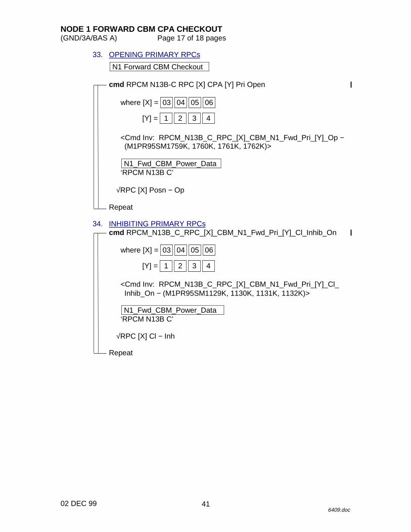
33. OPENING PRIMARY RPCs
N1 Forward CBM Checkout
cmd RPCM N13B-C RPC [X] CPA [Y] Pri Open
where [X] = 06050403
[Y] = 4321
<Cmd Inv: RPCM_N13B_C_RPC_[X]_CBM_N1_Fwd_Pri_[Y]_Op −(M1PR95SM1759K, 1760K, 1761K, 1762K)>
N1_Fwd_CBM_Power_Data‘RPCM N13B C’
√RPC [X] Posn − Op
Repeat
34. INHIBITING PRIMARY RPCscmd RPCM_N13B_C_RPC_[X]_CBM_N1_Fwd_Pri_[Y]_Cl_Inhib_On
where [X] = 06050403
[Y] = 4321
<Cmd Inv: RPCM_N13B_C_RPC_[X]_CBM_N1_Fwd_Pri_[Y]_Cl_Inhib_On − (M1PR95SM1129K, 1130K, 1131K, 1132K)>
N1_Fwd_CBM_Power_Data‘RPCM N13B C’
√RPC [X] Cl − Inh
Repeat
41
NODE 1 FORWARD CBM CPA CHECKOUT(GND/3A/BAS A) Page 18 of 18 pages
02 DEC 996409.doc
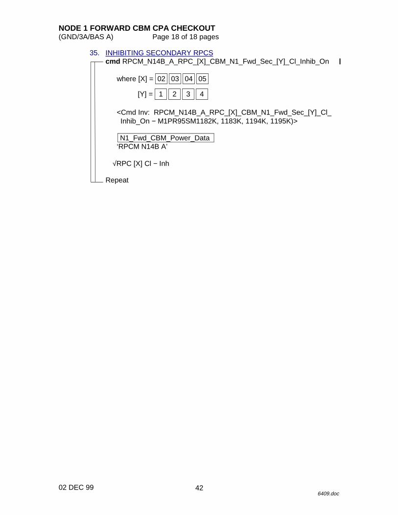
35. INHIBITING SECONDARY RPCScmd RPCM_N14B_A_RPC_[X]_CBM_N1_Fwd_Sec_[Y]_Cl_Inhib_On
where [X] = 05040302
[Y] = 4321
<Cmd Inv: RPCM_N14B_A_RPC_[X]_CBM_N1_Fwd_Sec_[Y]_Cl_Inhib_On − M1PR95SM1182K, 1183K, 1194K, 1195K)>
N1_Fwd_CBM_Power_Data‘RPCM N14B A’
√RPC [X] Cl − Inh
Repeat
42

12 JUN 00
TCS PROCEDURES
TCS
43

12 JUN 00
This Page Intentionally Blank
TCS
44
PMA 3 HEATER CHECKOUT(GND/3A/FIN) Page 1 of 4 pages
12 JUN 006254.doc
Identification Section:Procedure Name: PMA3 Heater CheckoutApplicability: 3AFrequency: RareObjective: To verify the PMA 3 shell heater functionality.Description: This procedure verifies the PMA 3 shell heater functionality.
VSS2 version 14.Crew Required: GroundPower: TBDData: Cyclic TelemetryDuration: 30 minutesLocation: MCC-HParts: NoneMaterials: NoneTools: NoneConstraints: NoneReference Materials: Node Control Software SRSAssumptions: NoneDefinitions: X = Heater Designator (i.e., 1B)
Y = the RPC corresponding to the heater you are enabling (i.e., 2)
45
PMA 3 HEATER CHECKOUT(GND/3A/FIN) Page 2 of 4 pages
12 JUN 006254.doc
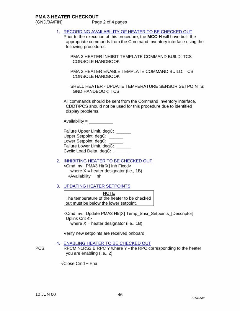
1. RECORDING AVAILABILITY OF HEATER TO BE CHECKED OUTPrior to the execution of this procedure, the MCC-H will have built theappropriate commands from the Command Inventory interface using thefollowing procedures:
PMA 3 HEATER INHIBIT TEMPLATE COMMAND BUILD: TCSCONSOLE HANDBOOK
PMA 3 HEATER ENABLE TEMPLATE COMMAND BUILD: TCSCONSOLE HANDBOOK
SHELL HEATER - UPDATE TEMPERATURE SENSOR SETPOINTS:GND HANDBOOK: TCS
All commands should be sent from the Command Inventory interface.CDDT/PCS should not be used for this procedure due to identifieddisplay problems.
Availability = __________
Failure Upper Limit, degC: ______Upper Setpoint, degC: ______Lower Setpoint, degC: ______Failure Lower Limit, degC: ______Cyclic Load Delta, degC: ______
2. INHIBITING HEATER TO BE CHECKED OUT<Cmd Inv: PMA3 Htr[X] Inh Fixed>
where X = heater designator (i.e., 1B)√Availability − Inh
3. UPDATING HEATER SETPOINTS
NOTEThe temperature of the heater to be checkedout must be below the lower setpoint.
<Cmd Inv: Update PMA3 Htr[X] Temp_Snsr_Setpoints_[Descriptor]Uplink Crit 4>
where X = heater designator (i.e., 1B)
Verify new setpoints are received onboard.
4. ENABLING HEATER TO BE CHECKED OUTPCS RPCM N1RS2 B RPC Y where Y - the RPC corresponding to the heater
you are enabling (i.e., 2)
√Close Cmd − Ena
46
PMA 3 HEATER CHECKOUT(GND/3A/FIN) Page 3 of 4 pages
12 JUN 006254.doc
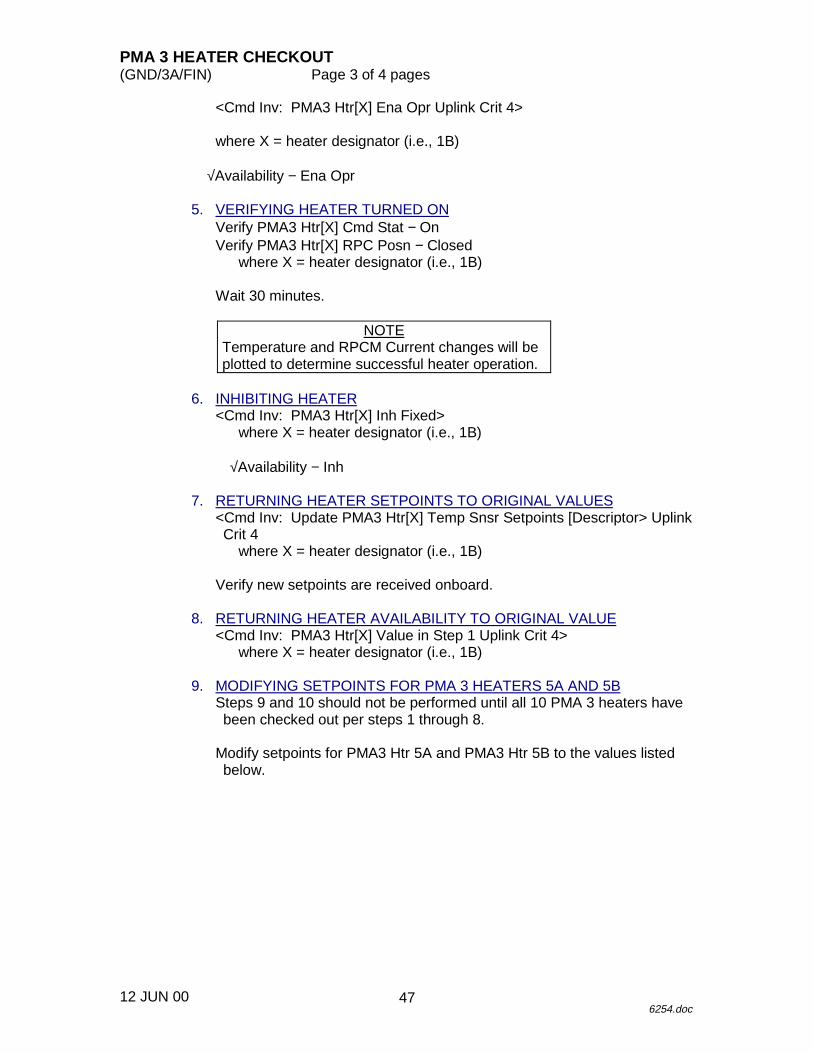
<Cmd Inv: PMA3 Htr[X] Ena Opr Uplink Crit 4>
where X = heater designator (i.e., 1B)
√Availability − Ena Opr
5. VERIFYING HEATER TURNED ONVerify PMA3 Htr[X] Cmd Stat − OnVerify PMA3 Htr[X] RPC Posn − Closed
where X = heater designator (i.e., 1B)
Wait 30 minutes.
NOTETemperature and RPCM Current changes will beplotted to determine successful heater operation.
6. INHIBITING HEATER<Cmd Inv: PMA3 Htr[X] Inh Fixed>
where X = heater designator (i.e., 1B)
√Availability − Inh
7. RETURNING HEATER SETPOINTS TO ORIGINAL VALUES<Cmd Inv: Update PMA3 Htr[X] Temp Snsr Setpoints [Descriptor> UplinkCrit 4
where X = heater designator (i.e., 1B)
Verify new setpoints are received onboard.
8. RETURNING HEATER AVAILABILITY TO ORIGINAL VALUE<Cmd Inv: PMA3 Htr[X] Value in Step 1 Uplink Crit 4>
where X = heater designator (i.e., 1B)
9. MODIFYING SETPOINTS FOR PMA 3 HEATERS 5A AND 5BSteps 9 and 10 should not be performed until all 10 PMA 3 heaters havebeen checked out per steps 1 through 8.
Modify setpoints for PMA3 Htr 5A and PMA3 Htr 5B to the values listedbelow.
47
PMA 3 HEATER CHECKOUT(GND/3A/FIN) Page 4 of 4 pages
12 JUN 006254.doc
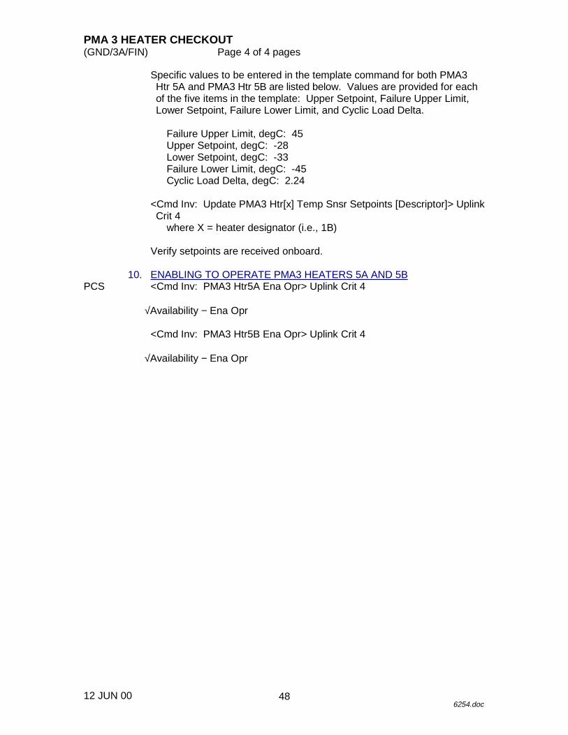
Specific values to be entered in the template command for both PMA3Htr 5A and PMA3 Htr 5B are listed below. Values are provided for eachof the five items in the template: Upper Setpoint, Failure Upper Limit,Lower Setpoint, Failure Lower Limit, and Cyclic Load Delta.
Failure Upper Limit, degC: 45Upper Setpoint, degC: -28Lower Setpoint, degC: -33Failure Lower Limit, degC: -45Cyclic Load Delta, degC: 2.24
<Cmd Inv: Update PMA3 Htr[x] Temp Snsr Setpoints [Descriptor]> UplinkCrit 4
where X = heater designator (i.e., 1B)
Verify setpoints are received onboard.
10. ENABLING TO OPERATE PMA3 HEATERS 5A AND 5BPCS <Cmd Inv: PMA3 Htr5A Ena Opr> Uplink Crit 4
√Availability − Ena Opr
<Cmd Inv: PMA3 Htr5B Ena Opr> Uplink Crit 4
√Availability − Ena Opr
48