
INTERNATIONAL SOCIETY FOR ROCK MECHANICS … · INTERNATIONAL SOCIETY FOR ROCK MECHANICS ... of...
13
Int. J. Rock Mech. Min. Sci. & Geomech. Abstr. Vol. 22, No. 2, pp. 71-83, 1985 0148-9062/85 $3.00+0.00 Printed in Great Britain Pergamon Press Ltd INTERNATIONAL SOCIETY FOR ROCK MECHANICS COMMISSION ON TESTING METHODS SUGGESTED METHOD FOR ROCK ANCHORAGE TESTING Joint Co-ordinators W. E. Lardner (Canada) and G. S. Littlejohn (U.K.) The following persons contributed in the drafting of this Suggested Method: J. A. Franklin (Canada); P. Habib and M. Gandais (France): T. H. Hanna (U.K.); J. Huder (Switzerland); D. E. Weatherby (U.S.A.). 71
Transcript of INTERNATIONAL SOCIETY FOR ROCK MECHANICS … · INTERNATIONAL SOCIETY FOR ROCK MECHANICS ... of...

Int. J. Rock Mech. Min. Sci. & Geomech. Abstr. Vol. 22, No. 2, pp. 71-83, 1985 0148-9062/85 $3.00+0.00 Printed in Great Britain Pergamon Press Ltd
INTERNATIONAL SOCIETY FOR ROCK MECHANICS
COMMISSION ON TESTING METHODS
SUGGESTED METHOD FOR ROCK ANCHORAGE TESTING
Joint Co-ordinators W. E. Lardner (Canada) and G. S. Littlejohn (U.K.)
The following persons contributed in the drafting of this Suggested Method: J. A. Franklin (Canada); P. Habib and M. Gandais (France): T. H. Hanna (U.K.); J. Huder (Switzerland);
D. E. Weatherby (U.S.A.).
71


ISRM: ROCK ANCHORAGE TESTING 73
Suggested Method for Rock Anchorage Testing
INTRODUCTION
(a) Two distinct methods of loading are described, namely co-axial loading and remote loading, the choice of appropriate method being dictated by the design engineer.
Co-axial loading is most commonly applied to test fixed anchor bond strength where the surrounding rock mass is not allowed to fail. Accordingly, the method is generally used only where the anchorage is deeply embedded (rock mass failure unlikely) or solely for the purpose of rock reinforcement.
Remote loading is applied to evaluate the strength of the anchorage in combination with the surrounding rock mass. This method is essential in shallow applications where the anchorage is resisting uplift, e.g. in the foun- dation of a transmission tower.
(b) Using either of these methods, a variety of tests may be conducted. Tests on rock anchorages can gener- ally be classified into two groups:
Design Tests--which are basic proving tests, may be required to demonstrate or investigate, in advance of the installation of working anchorages, the quality and adequacy of the design in relation to ground conditions and materials used, e.g. levels of safety provided by the design. The tests may be more rigorous than proof tests and the results, therefore, cannot always be directly compared, e.g. where short fixed anchors of different lengths are installed and tested, ideally to failure. On the other hand, where test anchorages are constructed under identical conditions as the proposed working anchorages and loaded in the same way to the same level, these tests indicate in advance the results that should be obtained from the working anchorages. The period of monitoring should be sufficient to ensure that prestress or creep fluctuations stabilize within tolerable limits. These are generally long term tests, e.g. in excess of 2 days, which are outside the scope of this document. Long term monitoring of anchorages is to be dealt with in a forthcoming Suggested Method.
Proof Tests--which are routine acceptance tests, are carried out on every anchorage and demonstrate the short term ability of the anchorage to support a load that is greater than the design working load and the efficiency of load transmission to the fixed anchor zone.
* Terms in italic type are defined in Definitions at the end of the text.
A proper comparison of the short term results with those of Design Tests on identical anchorages provides a guide to longer term behaviour.
(c) In this document no attempt has been made to describe anchorage design methods. The main objective is to define test methods and to specify performance parameters that may, if judged appropriate by the design engineer, be employed as criteria for the evaluation of anchorage behaviour. Since testing involves the use of stressing equipment, design considerations are intro- duced for such equipment and monitoring instrumen- tation together with guidelines on stressing procedures which are applicable to all classes of test and methods of loading.
(d) The procedures outlined in this document cover not only anchorages founded entirely within rock but also systems passing through soil or structural materials where the fixed anchor is embedded in rock. Such applications include retaining wall tiebacks, rock rein- forcement in excavations and anchorages for the pre- stressing of concrete gravity dams.
(e) Whilst it is hoped to achieve some degree of standardization in rock anchorage testing through this document, it is not all-encompassing nor should it be regarded in a restrictive way; the improvement of tech- niques is to be encouraged, as is the development of new concepts.
SCOPE
1. (a) This Suggested Method provides guidelines on a variety of tests for rock anchorages, including Design Tests and Proof Tests.* In addition, this document suggests equipment, measurements, calculations and records which are suitable for these two classes of tests. The long-term monitoring of anchorages is treated in a separate Suggested Method.
(b) Two alternative methods of loading are normally considered in practice. In the co-axial loading method, (Figs 1 and 2) the rock immediately surrounding the anchor head is used as a bearing surface for the stressing device; thus, rock movement or rock mass failure cannot be tested. Where rock mass failure in the form of a cone, wedge or block is a possibility then the remote loading method is appropriate, whereby the reaction loads are applied via a beam or grillage, to the ground surface remote from the test anchorage. The span between reaction points must be sufficient to allow rock mass

74 ISRM: ROCK A N C H O R A G E TESTING
' ~ / ~ LOAD CELL //
YDRAULIC JACK
DIAL GAUGE # MEASURES TENDON EXTENSION
x
L---HYDRAULIC PUMP WITH PRESSURE GAUGE
Fig. 1. Co-axial testing.
--TENDON
IG PLATE
BED
PREPARE A FLAT ROCK SURFACE BY CHIPPING AND HAMMERING
failure, if the rock is weaker than the steel tendon or its bond strength to the rock./* For example, if a conical or wedge type of failure is anticipated with an included angle of 45 °, the free span should not be less than the total embedded depth (Fig. 3). For laminar type failure in horizontally bedded "slabby" rock, free spans may be increased or decreased depending upon fracture geome- try. In cases where the rock is separated from the reaction structure by a considerable thickness of over- burden soil (as in Figs 4 and 12), the effect of the overburden's surcharge in restraining rock mass failure must be evaluated.
APPARATUS
2. Tools and materials are required, to allow prepara- tion of the reaction surface around each test anchorage, including for example rock chisels, hammers, and quick set grout for rock surface preparation or picks, shovels, backhoe, and timber cribs for soil surface preparation.
3. Loading and load measuring equipment are needed including:
(a) One or more hydraulic jacks 2 with bearing plates, wedges, shims, and other reaction/load transfer equip- ment sufficient to ensure that the load is applied co- axially with the Tendon throughout the test. Usually a single centre-hole hydraulic jack is employed with a firmly seated base plate, Anchor Head or nut(s) to transfer load from the jack to the tendon. A spherical seating beneath the anchor head or nut is desirable; when such a seating is not used, care must be taken to ensure co-axial alignment of jack and tendon and to provide adequate resistance against tilting or lateral translation of the jack or base plate.
(b) One or more hydraulic pumps 3 is necessary to pressurize the jacks and to maintain the applied load constant during readings.
(c) One or more hydraulic gauges should be used to measure the load applied to the anchorage.* Load cells [preferably mechanical] may also be used for this pur- pose.
* Superscript numbers refer to Notes at the end of the text.
NOTE :
THE GROUT BED MUST BE LARGE ENOUGH TO KEEP COMPRESSIVE STRESS WITHIN THE SAFE CAPACITY OF THE ROCK OR SOIL
Fig. 2. Co-axial testing.
The load measuring equipment should be provided with independently certified calibration graphs as noted in paragraph 5.
Load cell types applicable to anchorages include: (i) mechanical [based on proving ring systems] up to
PLAN A'A
~ u m m
REFERENCE BEAM, - - ~ SUPPORTED INDEPENDENTLY ~=,, ~ D I A L GAUGE, ATTACHED
TO REFERENCE BEAM STEEL FRAME - - TRANSFERS LOAD ~ CAP ON TENDON AWAY FROM ROCK ' ~ PROVIDING TENSILE ~ ~ " " ~ TENDON A'A v CAPACITY (Nofe 1) [ '
COMPRESSION ~ / REACTION
/
P O S S I B L E ~ ~ i / FAILURE ZONE, \ i / MUST BE DEFINED
Fig. 3. Testing rock strength. Simplified layout of rock anchorage test.

ISRM: ROCK A N C H O R A G E TESTING 75
R E F E R E N C E ~ ~ D C F i E C T I O N
PUMP AND--~ ~ / - - -HYDRAULIC PRESSURE~ ~ , n:~n-'f JACK GAUGE ~ , ~ [ ',~' . ~
. ~'J F STEEL BEAMS (N°'eI,
I l l I . . . .
I I
"i I I I I --EXCAVATE AND
COMPACT AS REQUIRED
I I I L l I TO O TA,. EAR,.G SURFACE AT RIGHT 1 ANGLES TO THE .
~i ~ -
Fig. 4. Testing rock strength.
2000kN capacity, force measuring blocks, up to 10,000kN, and cup springs, for loads greater than 4500 kN.
(ii) strain gauged elements, up to 5000 kN, and (iii) vibrating wire systems, up to 10,000 kN. Other methods involving photoelasticity, hydraulics,
and springs have been used in practice. In all cases, at least l~o accuracy is preferred 5 and,
regardless of cell type, eccentric loading effects should be either assessed or prevented.
4. Equipment for measuring anchorage movement will include:
(a) Equipment that will permit measurement of move- ment of the anchor head in a direction co-axial with the tendon with reference to a stable datum, such as rock remote from the anchor head. The measuring equipment should be designed and installed so that it is robust and provides a measuring accuracy better than _+ 0.1 ram, unless otherwise specified (e.g. for simple proof tests), and have a range of ram travel not less than 75 mm or the anticipated full test extension, whichever is the greater.
(b) As with load cells, there are various levels of sophistication for measuring axial tendon extension or anchor head displacement. Methods generally utilize dial gauges, electric transducers, steel tape and surveying equipment.
(c) The simplest and least accurate method is to measure the jack ram extension by a steel rule. Since strand or wire slip can occur at the grip wedges, the true extension is overestimated for this type of tendon. A preferable method of measurement is one whereby a
piece of adhesive tape, or some other means, is used to mark the tendon at some distance above the permanent load bearing plate. This approach permits an accurate measurement of extension without removal of the jack, providing the bearing plate is not subjected to move- ment. Ram extensions are usually measured with a stiff steel rule, and an accuracy of _ 1 mm can be attained which is adequate for load extension data in practice.
(d) An example of a wire, mirror and scale displace- ment measuring system is shown in Fig. 5. The scale is fixed to the mirror and both are attached to the anchor- age. The wire is tensioned between remote fixing points so that it passes close to the scale. Readings to about + 1 mm can be obtained by lining up the wire with its mirror image.
(e) Where greater accuracy is required e.g. creep displacement monitoring with time, dial gauges attached to a simply supported datum beam or tripod (Fig. 1). are recommended. Dial gauges with a reading accuracy of 0.05 mm are adequate for the majority of test applica- tions.
(f) All reference beams, wires etc., must have indepen- dent supports firmly embedded in ground far enough from the test anchorage and compressive reactions to ensure they are not moved more than 0.1 mm by anchor- age or jack movements. Reference beams must be sufficiently stiff to support the instrumentation such that variations greater than +_ 0.1 mm in readings do not occur. They can be cross connected to provide additional rigidity. Reference beams when used must be protected from or be insensitive to wind, humidity and tem- perature changes, e.g. they should have one end free to move laterally to accommodate temperature variations.

76 ISRM: ROCK ANCHORAGE TESTING
TENDON OR ANCHOR HEAD
A! yA
PIANO WIRE (
MIRROR WITH SCALE
ELEVATION
~ TENDON
/-
PLAN SECTION A-A
Fig. 5. Simple displacement measuring system.
/ STRESSING JACK • . / ANCHOR HEAD PLATE
~ " ~ / / TENDON LE WIRE
. . . . 7 " - % 0
"1 ~ID-E P-E NB-E N T LY ~ ~
Fig. 6. Direct method of measuring fixed anchor movement.
(g) A direct, as opposed to interpretive, method of measuring the amount of fixed anchor movement in- volves the embedment of a wire in the fixed anchor. The wire is deeoupled, i.e. sheathed over the free length, and extends out of the anchor head assembly. With the wire loaded in tension, simply to keep it taut, the wire movement indicates fixed anchor movement (Fig. 6). Alternatively, a redundant tendon unit may be used in place of a wire. Figure 7 shows a wire pulling system for measuring anchor head displacement.
(h) Miscellaneous equipment including a stopwatch, field data sheets are needed to record the test results, pens, clipboards, and marking equipment to label the anchorages tested.
PULLEY ~ ,~/~
W I R E ~ / / " JAcK - - 7
MEASURING THE " ~ ]:~ )~" "%. '~ '~ WIRE MOVEMENT J~l~l~ "~ "'~I'~X"~.%~
STEEL SUPPORT ~ SECURELY FIXED TO THE GROUND, REMOTE FROM THE ANCHORAGE
Fig. 7. Direct method of measuring anchor head displacement.

ISRM: ROCK ANCHORAGE TESTING 77
PROCEDURE
Calibration
5. (a) All jacks and pressure gauges must be cali- brated prior to use and the calibration certificate be made available for inspection on site at all times.
(b) Jacks should be calibrated at least every year using properly designed test equipment which has an Absolute Accuracy not exceeding 0.5~ and the test records should tabulate the relation between the load carried by the jack and the hydraulic pressure when the jack is in the active mode with load both increasing and decreasing.
The jack calibration should be checked prior to the start of tensioning on each contract and a calibration curve prepared for each jack.
The calibration should extend from zero over the full working range of the jack and should be established for the opening (load rising) and closing (load falling) operation of the jack, so that the friction hysteresis can be known when repeated loading cycles are being carried out on the tendon. This requires calibration at several ram extensions, e.g. 25, 50 and 75Vo full ram travel.
(c) Load cell(s) may be used in series with the hydrau- lic jack(s). Load cell(s) should be calibrated prior to the test to an accuracy of not less than 1~o of the Specified Maximum Test Load (SMTL) and will generally need to be equipped with spherical or machined seating(s) to give the required measuring accuracy.
(d) Calibration reports are to be certified by an independent and approved testing laboratory. They should be furnished for all testing equipment for which calibration is required, and are to be available at the time of testing and dated not more than 6 months prior to that time.
Test surface preparation
6. (a) When reaction is to be provided by rock or concrete, the reaction surface should be cleaned of all loose or soft materials and prepared plane and at right angles to the applied load. A machine or hand chisel can be used to prepare the surface roughly, after which steel plates can be placed and bedded accurately on a grout cushion or using wedges (Fig. 2).
(b) When the reaction is to be provided by over- burden soil, the reaction structure must be designed to transmit the loads to the soil without excessive move- ment. Normal stresses must be kept within acceptable levels. Incompetent soil should be removed or com- pacted, and footings such as timber cribs constructed (Fig. 4).
(c) In cases where the rock anchorage is to act on a structure such as a temporary retaining wall, a portion of the wall itself can often provide adequate support.
(d) Where the bearing plate is bedded to the ground or structure through a concrete plinth or pad, i.e. where the depth of concrete exceeds 10~ of the bearing plate width or 100mm, the plinth should be designed in accordance with FIP standards (F6d6ration Inter- nationale de la Pr6contrainte) or national standards for post-tensioned concrete and blocks.
(e) Deterioration of a newly exposed rock surface must be prevented. It may, for example, be necessary to clean the rock surface and protect it with gunite.
7. The loading and reaction equipment is then assem- bled on the prepared surface. A small load, less than 5~ of the Specified Maximum Test Load [SMTL] is to be applied and the system checked for stability. The pres- sure gauge and pump should be at a safe location.
Setting up the extension measuring system
8. (a) The extension measuring system is assembled and checked to ensure that it meets the requirements of paragraph 4.
(b) All gauges, and other data sources should be clearly marked with a number or letter to assist in recording data. Provisions should be made to securely fix and to protect the measuring system, reference system and instrumentation from extreme temperature vari- ations and from mechanical disturbances.
(c) Measurement of the extension of the tendon should when possible be made directly onto the end of the tendon; flexible tendons should be guided to prevent lateral movements (Fig. 8). For simple tests, e.g. Proof Tests, the jack extension may be monitored but cor- rected for any measured movement of the base of the jack.
(d) Dial gauges when employed should be mounted on a reference beam so as to bear upon a prepared flat surface or cap on the anchor head or tendon. The surface or cap should be big enough so that the dial gauge plunger remains in contact throughout testing. In some cases it may be convenient to employ two or more gauges equidistant from the anchorage axis so that the average reading can be taken as the anchorage displace- ment.
TEN
NUT OR~ STRESSING HEAD
i.~-----~-DIAL GAUGE
FLAT SURFACE PERPENDICULAR TO LONGITUDINAL AXIS OF TENDON
GUIDE FOR TENDON iF NECESSARY
~ PLATE
Fig. 8. System for measuring tendon displacement, but with lateral movement restricted.

78 ISRM: ROCK ANCHORAGE TESTING
Testing
9. (a) Design Tests are undertaken before the installa- tion of working anchorages. They provide criteria to substantiate the design parameters used and to define acceptable performance 6 of service anchorages during proof testing.
In this paragraph a general test procedure is sug- gested, modifications may be made if required for a particular site.
(i) In the following procedure, test variables SMTL, Pl, N, It, and 12, are included which must be defined in the test specifications to suit the objectives of the test programme. Typical values are shown in Table 1.
(ii) Apply a small bedding-in load PI less than 5~o of SMTL; allow the jack to stabilize, then check all gauges and readings of load and corresponding displacements. Increase the applied load in steps o f N ~ SMTL stopping at each step to take readings of extension; hold each load step for a period of t~ min. All measurements should be taken in the rising mode.
(iii) Hold the applied load [P2, P3, etc.] steady (+ 2~o SMTL) at each step and take 5 sets of readings at intervals of approximately 1 rain; however, when creep occurs significantly greater than the anticipated creep of the tendon steel, the applied load should be maintained until such excessive creep ceases, (see ix and Table 2 below).
(iv) On completion of each loading step reduce the load to P~ holding this steady and taking a reading of permanent deformation before proceeding to the next loading step.
(v) On reaching SMTL maintain the applied load constant within + 29/o SMTL for a period of t 2 min. Take readings of load, load displacement and time at intervals of 5 min during the first 30 min, then at intervals of 30 min for durations up to 3 hr, t h e n at intervals of 1 hr until t 2 is reached.
(vi) On completing step (v) repeat the unloading procedure given in parts (iv), then remove load and equipment.
Table 1. Suggested test parameter values Full design Simplified
test design test Proof test SMTL 2 × Working load [2 x Pw] 1.25-1.50 Working load Pj . . . . less than 5% SMTL .. . . N 10~/o 20% 100% t~ 5 min 5 rain N/A t 2 1500 min 20 rain 10 min
Table 2. Suggested allowable creep displacement or load relaxation
Period of observation Permissible loss of load (min) or displacement (%)
5 1 15 2 50 3
150 4 500 5
1500 6 Notes: (i) Permissible loss of load is expressed as a ~ of the applied load [P]. (ii) Permissible displacement is expressed as a % of elastic extension at the applied load [P].
(vii) If required, the loading cycle may be repeated, one or a number of times.
(viii) If failure occurs, continue the loading process only as desirable to determine the reason for failure. Record the nature of the failure and the failure load.
(ix) Delays t~, and t, can be curtailed and loading/unloading continued if any two successive read- ings show a rate of movement of less than the allowable creep shown in Table 2.
(b) Proof Tests, carried out on all working anchor- ages, can employ procedures similar to Design Tests, but are generally abbreviated and much simpler.
(i) Follow steps (i) through (v) in 9(a). (ii) On completing step (v) the load is released to the
specified "Lock-off Load", the tension is transferred from the jack to the nut/anchor head, and the test equipment is removed. An exception is when the anchor- age has failed to meet the specified acceptance criteria, in which case further stages of testing may be required by the testing contract specifications.
(iii) An alternative procedure frequently followed for simple proof tests is to record the loss of load over a short period of time after the SMTL has been applied. Provided the loss of load is within specified limits (see Table 2) the anchorage is deemed acceptable.
(c) General. The method of tensioning to be used, the sequence of stressing and the procedures to be adopted for each stressing operation should be specified at the planning stage of a project, The equipment should be used strictly in accordance with the manufacturer's operator instructions.
For cementitious grouts, stressing should not com- mence until the primary grout forming the fixed anchor has attained a crushing strength of at least 30 MPa, as verified from tests on appropriate grout samples. No tendon that is to form part of any temporary or per- manent works should be stressed at any time beyond 80~ of the characteristic strength.
(d) Check-lifting. Check-lifting is the technique of using the stressing jack straddling over the stressing head to lift it clear of its distribution plate to record the tendon load with the jack pressure gauge or load cell. The distance the anchor head is raised, normally 1 mm, although this may be as low as 0.1 mm, should be fixed and the method of measurement should ensure that all sides of the stressing head are clear of the distribution plate (see Fig. 9).
(e) When a stressing operation is the start point for future time-related measurements, the stressing oper- ation should be concluded with a check-lift load mea- surement, following the exact procedure to be used for subsequent check-lifts in order to minimize operational error.
(f) Unit stressing. The procedure for stressing multi- unit tendons using a number of hydraulically syn- chronized monojacks or individual monojacks, should allow for the fact that, when stressing is carried out using an individual monojack, the possible change in load in adjacent tendon units should be appreciated. Such load changes generally result from frictional forces between

ISRM: ROCK ANCHORAGE TESTING 79
A STEEL BAR CEMENT G R O U T - ~ . ~ ~
G~ "--N--" r r _ . ~ li ~ ~ BEARING PL ~E ~
L--.. DEFLECTION ] ' ~ ~ . ~ DIAL GAUGE I L \ ~ EXTENSION I I"---... \ SLEEW I I REACT,ON CHAIR " ~ ~ HYDRAULIC JACK
L A A.A Fig. 9. Jack arrangement for mono-unit stressing and measuring of residual load.
adjacent units in the free length and from the permanent displacement of the fixed anchor grout during loading.
These effects can be reduced by application of small load increments and can generally be eliminated by repeat application of load, unless permanent displace- ment is continuous. At any time, the load in each individual tendon unit can be measured by a lift-off check.
(g) For anchorages that have failed a proof load criterion, some additional tendon unit stressing may help to ascertain location of failure, e.g. for a temporary anchorage, pull-out of individual tendon units may indicate debonding at the grout/tendon interface; whereas, if all tendon units hold their individual proof loads, attention is directed towards failure of the fixed anchor at the ground/grout interface.
(h) Health hazards and safety. During stressing, ade- quate precautions should be taken to protect personnel and property from injury and damage due to rupture of a tendon or failure of the stressing equipment.
Persons not engaged in the works, including members of the public, should also be protected. In this regard, strong barricades should be erected beyond the anchor head in line with any exposed ends during tensioning. The barricades should be strong enough to absorb a significant proportion of the tendon energy if it should be accidentally released.
The space between the anchor head and the barricade should be roped off to prevent unauthorized passage.
Notices should be displayed stating "DANGER-- Tensioning in Progress" or similar wording.
Operatives and observers should stand to one side of the tensioning equipment and never pass behind when it is under load,
Data reduction
10. (a) When applied loads are measured as hydraulic pressure in the jacks, the total applied load at each increment is calculated, multiplying the hydraulic pres- sure by the effective piston area per jack, and by the
number of jacks employed, making use of the jack calibration curves to correct for frictional and other effects.
(b) Displacements measured by more than one gauge or by electrical transducers or surveying techniques are reduced to a single equivalent displacement of the an- chor head along the axis of the anchorage. In some cases it may be necessary to correct the readings, for example when the reference datum itself moves, when ram exten- sion is measured and the ram moves, or when gauges are re-set during the tests.
Graph plotting 11. As well as being tabulated, the results are to be
plotted graphically as shown in Figs 10 and !1. The graphs should show all points of measurement. The graph of load-displacement (Fig. 10) should include for comparison straight lines corresponding to the Theoretical Elastic Extension (see paragraph 12) of the tendon and its elastic limit.
ELASTIC LIMIT OF TENDON
/ S M T L . . . . . /_
I /
...D/ . S i l l II
i / i / A p / / I , x
I LL/--,-- C- --I-- o
DISPLACEMENT
Fig. 10. Load--displacement curve.
/ / / '
f / PLASTIC
S ELASTIC
/ -I
80 ISRM: ROCK ANCHORAGE TESTING
\. ~o \
\
ELASTIC EXTENSION
t~ O. kd
"q t~
P,
- - P,
PLASTIC EXTENSION
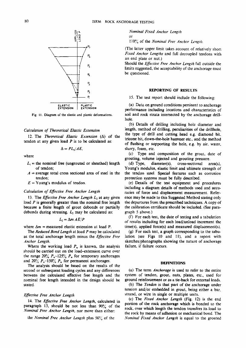
Fig. 11. Diagram of the elastic and plastic deformations.
Calculation of Theoretical Elastic Extension
12. The Theoretical Elastic Extension (A) of the tendon at any given load P is to be calculated as:
A = PLI/AE,
where
L1 = the nominal free (ungrouted or sheathed) length of tendon;
A = average total cross sectional area of steel in the tendon;
E = Young's modulus of tendon.
Calculation of Effective Free Anchor Length
13. The Effective Free Anchor Length L2 at any given load P is generally greater than the nominal free length because a finite length of grout debonds or partially debonds during stressing. L2 may be calculated as:
where Am = measured elastic extension at load P. The Reduced Bond Length at load P may be calculated
as the total anchorage length minus the Effective Free Anchor Length.
Where the working load Pw is known, the analysis should be carried out on the load-extension curve over the range 20~ Pw-125~ Pw for temporary anchorages and 20~o Pw-150% Pw for permanent anchorages.
The analysis should be based on the results of the second or subsequent loading cycles and any differences between the calculated effective free length and the nominal free length intended in the design should be stated.
Effective Free Anchor Length
14. The Effective Free Anchor Length, calculated in paragraph 13, should be not less than 90% of the Nominal Free Anchor Length, nor more than either:
the Nominal Free Anchor Length plus 50~o of the
Nominal Fixed Anchor Length or
110% of the Nominal Free Anchor Length.
(The latter upper limit takes account of relatively short Fixed Anchor Lengths and full decoupled tendons with an end plate or nut.) Should the Effective Free Anchor Length fall outside the limits suggested, the acceptability of the anchorage must be questioned.
R E P O R T I N G O F R E S U L T S
15. The test report should include the following:
(a) Data on ground conditions pertinent to anchorage performance including locations and characteristics of soil and rock strata intersected by the anchorage drill- hole.
(b) Details of drilling including hole diameter and length, method of drilling, peculiarities of the drillhole, the type of drill and cutting head e.g. diamond bit, tricone bit, down-the-hole hammer etc., and the method of flushing or supporting the hole, e.g. by air. water, slurry, foam, etc.
(c) Type and composition of the grout, date of grouting, volume injected and grouting pressure.
(d) Type, diameter(s), cross-sectional area(s), Young's modulus, elastic limit and ultimate strength of the tendon steel. Special features such as corrosion protection systems must be fully described.
(e) Details of the test equipment and procedures including a diagram details of methods used and accu- racies of force and displacement measurement. Refer- ence may be made to this Suggested Method stating only the departures from the prescribed techniques. A copy of the calibration certificate should be included. (See para- graph 5 above.)
(f) For each test, the date of testing and a tabulation of results including for each load/unload increment the time(s), applied force(s) and measured displacement(s).
(g) For each test, a graph corresponding to the tabu- lation (see Figs 10 and 11), and a report with sketches/photographs showing the nature of anchorage failure, if failure occurs.
D E F I N I T I O N S
(a) The term Anchorage is used to refer to the entire system of tendon, grout, nuts, plates, etc., used for ground reinforcement or as a tie-back for external loads.
(b) The Tendon is that part of the anchorage under tension and/or embedded in grout, being either a bar, strand, or wire in single or multiple units.
(c) The Fixed Anchor Length (Fig. 12) is the end portion of the rock anchorage which is bonded to the rock, over which length the tendon transfers its load to the rock by means of adhesion or mechanical bond. The Nominal Fixed Anchor Length is equal to the grouted

ISRM: ROCK ANCHORAGE TESTING 81
ANCHOR -"7 " ~
// / / PLATE F'DR"" HOLE / / / /
STRUCTURE ~ / TO BE ANCHORED SHOULD BE M O N I T O R E D " - ~ X ~ D , ~ . . / DURING TEST
BOND BREAKER-- OR TENDON SH~ ATH
Fig. 12. Nomenclature for a ground anchorage.
(unsheathed) length. The Reduced Bond Length is equal to the total anchorage length less the Effective Free Length at a specified load.
(d) The Nominal Free Anchor Length is equal to the ungrouted or sheathed length. The Effective Free Anchor Length is calculated from the elastic extension of the tendon and accommodates the degree of debonding in the fixed anchor length.
(e) Ultimate Strength of a rock anchorage or one of its components is the load at failure, i.e. the load above which measurable creep occurs at a uniform or acceler- ating rate.
(f) A Proof Test is one carried out on service anchor- ages following their installation as part of the support system to confirm that these (or selected) anchorages meet specified performance criteria. It is not intended to be a destructive test.
(g) Proof Load is the test load that proves that an anchorage has sufficient capacity to resist the loads that may be imposed upon it in service, with an adequate load factor of safety. Generally, a rock anchorage is designed so that the ultimate strength of each of its components is in excess of its Design Load by factors which are considered adequate when taking into account variability of material properties, dimensions and work- manship etc. Typical Proof Load is in the range 1.25-1.50 x Design Load, but may be varied at the discretion of the designer depending on the application.
(h) Design Load or Working Load in the case of a working stress design, is the maximum load that has been calculated as being applied to the anchorage during service. In the case of a limit state design, it is the sum of the factored load components which could be applied during service.
(j) A Design Test is one generally carried out prior to the drafting of specifications to assist in selecting an appropriate anchorage design. Alternatively, the design test can check the suitability of a proposed anchorage
system, by monitoring the behaviour at working load over an extended time, to ensure stabilization of load relaxation or creep displacement. It should provide data, for example, on bond strength between grout and rock or tendon, on the effective free anchor length at various loads, and on creep performance. Where such tests are taken to failure the tested anchorages seldom can be used in service.
(k) Characteristic Strength--The value of cube strength of grout or concrete (fcu) or the ultimate load of a prestressing tendon (fpu), below which not more than 5% of the test results fall.
(m) Anchor Head--The component of a ground an- chorage that is capable of transmitting the tensile load from the tendon to the surface of the ground or structure requiring support.
(i) Normal type anchor head. An anchor head that is designed to permit the load in the tendon to be raised or lowered within the limits 0% fpu to 80% fpu and measured, when necessary to comply with the require- ments of acceptance testing. This facility is available during the initial stressing phase and subsequently, if the tendon is shortened, further measurement or adjustment is not possible.
(ii) Restressable type anchor head. An anchor head that has all the properties of the normal head and in addition permits the tendon, throughout the life of the structure, to be measured by check lifting and small losses, up to 109/o of working load, to be recovered by shimming or thread-turning.
(iii) Detensionable type anchor head. An anchor head that has all the properties of the restressable head and in addition permits the tendon to be detensioned in a controlled way at any time during the life of the structure.
(n) Lock-off Load--The load transferred to the anchor head immediately on completion of a stressing operation.

82 ISRM: ROCK ANCHORAGE TESTING
(o) Lift-off Load--The minimum load monitored during a restressing operation that permits a locking nut to turn on a bar tendon or provides a clearance or lift in the case of a wire or strand tendon.
(p) Residual Load--The load remaining in the an- chorage at any time-during service.
(q) Relaxation--The decrease of stress with time while the tendon is held under constant strain.
(r) Creep--The change in strain of the tendon with time under constant stress.
(s) Absolute Accuracy--The deviation from the true value, i.e. where the measuring instruments have been calibrated against dead weight apparatus or loading machines and the accuracy is known.
(t) Relative Accuracy--The deviation from the mea- sured value, i.e. the error in measurement where small changes in load or displacement are monitored against time.
(u) The Theoretical Elastic Extension of the anchor- age at any given load is equal to the calculated extension of the Nominal Free Anchor Length of tendon assuming that no grout debonding has occurred.
(v) The Specified Maximum Test Load (SMTL) is the maximum load which is to be applied to an anchorage during a test.
In the case of a design test, the SMTL would generally be at least twice the desired working load; in the case of a proof test, frequently SMTL can be taken as 1.33 times the working load Pw (the recommended range is 1.25-1.5Pw). In determining the sizes and strength characteristics of the components of a test anchorage, care must be taken to ensure that the SMTL does not overstress any portion of the anchor. Thus SMTL :~ 0.8 x characteristic strength of tendon. In ad- dition, stressing is not permitted until grout cube strength attains 30 MPa.
In the case of design tests, for example, it may be necessary to employ a tendon of greater strength than is proposed for the service anchorages, in order to test adequately the rock strength and the bond and adhesive strengths.
NOTES
1. Reaction beams may be subjected to considerable bending moments and should be cross-braced and struc- turally adequate for the applied loads.
2. As rock anchorage loads can be quite large--e.g. test loads over 100 t are quite common--the most suit- able tool for applying and controlling the load is usually one or more hydraulic jacks. Centre-hole jacks up to 100 t capacity are readily available and capable of being placed by hand; jacks of larger capacity are generally placed by machine. It may be convenient to use two or more jacks to provide high loads, in which case the jacks should be of the same ram diameter and connected via a common manifold to a single pump and pressure gauge. Jacks with travel (extension) of 150 mm or more should be employed. If possible, the jacks should be equipped with a means to allow the tendon to be initially
tensioned and anchored in increments to raise or lower the tendon force according to the tensioning recommen- dations and finally to be checkqifted to ascertain the tendon load.
3. Usually jacks are activated by an electrical or hand pump. If the former, it must have the capability of permitting the loading to be stopped at any point and then continued without first having to drop the pressure back to zero. Hydraulic pressures employed are usually up to 70 MPa.
Hydraulic pumps should be rated to operate through the pressure range of the stressing jack. The controls of the pump should allow the tendon extension to be easily adjusted to the nearest millimetre, whether the jack is opening or closing. The pressure gauge should be mounted such that it is reasonably free of vibration during pumping. All flexible connections between pump and jack should have a burst pressure at least twice the maximum pump pressure rating.
The pump unit should be equipped with a site- regulated pressure relief valve to prevent tendon damage by over-tensioning.
The pump must be connected to the jack(s) with hose long enough to permit the pump to be operated in safety. The hose should be fitted with quick-release non-spill connectors. If the hydraulic pump is to be left un- attended for a significant time during the test it should be equipped with an automatic regulator to hold the load constant as movement occurs.
4. At least one pressure gauge per test will be re- quired, and should be chosen to match the range of pressures to be used (e.g. a 70MPa gauge may not record pressures over a range 0-20 MPa with sufficient accuracy.) Consideration should be given to employing a second load measuring system (gauge and load cell) as a back-up in case one system malfunctions. This second gauge can, preferably, be used as a control gauge. Whenever there is a doubt about the working gauge, the control gauge can be mounted in parallel to compare the two. When not in use, keep the control gauge well packed and protected.
5. When loads are held for a relatively long period of time [e.g. t2 = 1500 min] in a climate where large tem- perature changes may be experienced, it may be neces- sary to allow a greater percentage variation than 1~/o. Additional optical readings---e.g, of the reference beam deflections--may be used to achieve greater accuracy.
6. Criteria that may be adopted for anchorage accept- ability include the following:
(a) The Reduced Bond Length (RBL) (i.e. the effective fixed anchor length) measured by testing to a SMTL which should be sufficient to give a margin of safety against long-term failure. If the RBL is significantly less than the Nominal Fixed Anchor Length, this indicates that substantial bond failure may have occurred during the test. Bear in mind that when the tendon is button-ended or has an end plate fixture embedded in the grout, the anchorage may continue to perform satisfactorily after the entire tendon-grout bond has yielded, provided that the grout rock bond is stronger.

ISRM: ROCK ANCHORAGE TESTING 83
In such cases, the RBL could assume zero or even negative values.
(b) Anchorages should maintain their working load. Suspect anchorages may be repeat-tested to measure their tension by a "lift-off" technique. I f the anchorage tension has fallen significantly between tests, this is an indication of progressive anchorage failure.
(c) When the Reduced Bond Length approaches zero, the anchorage may or may not be approaching failure, depending on its design. I f the bond between grout and rock has been the first to fail, the anchorage as a whole will be failing except, for example, in the case of an under-reamed anchorage. I f the bond between grout and tendon has been the first to fail, the anchorage as a whole will be approaching failure unless the tendon has an "anchor foot" (Fig. 12). In the latter case, bond failure between grout and tendon will be followed by com- pressive loading of the grout plug leading ultimately
to (progressive) failure of the bond between grout and rock.
Received 20 August 1984.
BIBLIOGRAPHY
1. Littlejohn G. S. and Bruce D. A. Rock Anchors: State-of-the-Art. Geo Publications Ltd, Brentwood (1977).
2. Douglas T. J. and Arthur L. J. A guide to the use of rock reinforcement in underground excavations. CIRIA Rept No. 101, London (1983).
3. Weatherby D. E. Tiebacks. U.S. Dept of Transportation. Federal Highway Administration Rept No. FHWA/RD-82/047 (1982).
4. Hanna T. H. Foundations in Tension. Trans Tech Pubns, Clausthal (1982).
5. Hobst L. and Zajic J. Anchoring in Rock. Elsevier, Amsterdam (1983).
6. American Society of Mechanical Engineers. Jacks--American National Standard ANSI B30.1 (1981).
7. Schnabel H. Jr. Tiebacks in Foundation Engineering and Construc- tion. McGraw Hill, New York (1982).
R.M,M.S. 22/2~C