International Linear Collider (ILC) Micromegas TPC...
46
11/16/04 1 Purdue U./Fermilab seminars: M. Ronan (LBNL) “ILC Micromegas TPC R&D” International Linear Collider (ILC) Large-Area Micromegas TPC R&D Mike Ronan LBNL (Berkeley) Berkeley – Orsay – Saclay Micromegas TPC R&D Collaboration As presented at Purdue, Fermilab & Carleton, 15-19 Nov. 2004
Transcript of International Linear Collider (ILC) Micromegas TPC...

11/16/04
1Purdue U./Fermilab seminars: M. Ronan (LBNL) “ILC Micromegas TPC R&D”
International Linear Collider (ILC) Large-Area Micromegas
TPC R&D
Mike RonanLBNL (Berkeley)
Berkeley – Orsay – SaclayMicromegas TPC R&D Collaboration
As presented atPurdue, Fermilab & Carleton, 15-19 Nov. 2004

11/16/04
2Purdue U./Fermilab seminars: M. Ronan (LBNL) “ILC Micromegas TPC R&D”
Outline● Micromegas TPC Design
– Construction, Purdue 3M Micromegas mesh
– Anode pad layout
● Cosmic Test Configuration
● Measured Gas Properties
– Drift velocity, Electron attachment, Transverse diffusion
● Micromegas TPC Performance Characteristics
– Gain, stability, noise
– Transverse position resolution
● Pixel TPC R&D
– Setup, MediPix chip (2D) readout

11/16/04
3Purdue U./Fermilab seminars: M. Ronan (LBNL) “ILC Micromegas TPC R&D”
International Linear Collider (ILC)
It will look somethink like

11/16/04
4Purdue U./Fermilab seminars: M. Ronan (LBNL) “ILC Micromegas TPC R&D”
Linear Collider Higgs Physics
Use Higgstrahlung process e+e- --> ZH with Z decaying into leptons to measure / confirm Higgs mass from LHC, and to determine branching ratios precisely.
N.B. Also, need to calibrate Higgs multi-jet reconstruction efficiency.

11/16/04
5Purdue U./Fermilab seminars: M. Ronan (LBNL) “ILC Micromegas TPC R&D”

11/16/04
6Purdue U./Fermilab seminars: M. Ronan (LBNL) “ILC Micromegas TPC R&D”
●ZHH
We'd like to use the “Double Higgstrahlung” process
e+e- --> ZHH --> 6 jetsto measure Higgs self-coupling and to improve
our understanding of the higgs potential.
N.B. Need jet reconstruction resolution to be better than 30%/sqrt(E) in multi-jet events.
Cross sections

11/16/04
7Purdue U./Fermilab seminars: M. Ronan (LBNL) “ILC Micromegas TPC R&D”
TPC SymposiumBerkeley, Oct.2003
R.-D. HeuerHamburg University
TESLA TPC Proposalor
A TPC for a Linear Collider Detector

11/16/04
8Purdue U./Fermilab seminars: M. Ronan (LBNL) “ILC Micromegas TPC R&D”
ILC Gaseous TPC Detector ModelIt might look somethink like

11/16/04
9Purdue U./Fermilab seminars: M. Ronan (LBNL) “ILC Micromegas TPC R&D”
TPC studies of e+e- collisions
From 2004 CERN Courier article bySpencer Klein, LBNL

11/16/04
10Purdue U./Fermilab seminars: M. Ronan (LBNL) “ILC Micromegas TPC R&D”
Multijet Higgsstrahlung events e.g. e+e- --> Z + Higgs --> 2-4 jets

11/16/04
11Purdue U./Fermilab seminars: M. Ronan (LBNL) “ILC Micromegas TPC R&D”
Linear Collider Physics & Detector Studies
World Wide Study (WWS) organization
● Form international study groups to address global physics and detector design issues.
● Begin to focus on two detector concepts:Large Gaseous Detector models * “medium” TESLA TDR design B = 4T, R
TPC = 1.7 m
“large” American model B = 3T, RTPC
= 1.9 m
“huge” Asian model B = 2.5-3T, RTPC
= 2.1 m
A Silicon-based Detector model “small” B = 5-6T, R
ECal = 1.5 m
* Note: Significant differences in Calorimeter options, see below.

11/16/04
12Purdue U./Fermilab seminars: M. Ronan (LBNL) “ILC Micromegas TPC R&D”
General view of “Large/Huge” detector size
Large / Huge
from Sachio Komamiya
B = 2.5-3TB = 4TB = 5-6T

11/16/04
13Purdue U./Fermilab seminars: M. Ronan (LBNL) “ILC Micromegas TPC R&D”
● Large TPC Reference Detector– Design parameters
● Medium sized TESLA TPC reference model– Background studies– Multijet event reconstruction studies– LC-TPC R&D
● Large Detector Calorimeter Models– Present American Large “Compensating” model– Large Thin W-Si ECal model– Hybrid Calorimeter models
Linear Collider Detector Studies

11/16/04
14Purdue U./Fermilab seminars: M. Ronan (LBNL) “ILC Micromegas TPC R&D”
American Large Detector DesignLarge reference tracking detector Large TPC Chamber ~ size of STAR TPC dimensions dia. 2 m, half-length 2.5 m pad layout 144-256 pad rows pads partout readout options: Wire or GEM or Micromegas
Electronics Next generation fully integrated over 1M channels
Magnet ECal and HCal inside. 3 T
Reconstruction 3D Pattern Recognition LCD Java Framework modular design
TPC Simulation smear space points with 100-140 m resolution no-detector effects
Tracking efficiency ~ 99% already
Detailed response simulation being developed along with R&D studies.
Z() + H(jets) event
Hits: TPC points (cyan), EM Cal hits (blue)Tracks (red), Clusters (green)

11/16/04
15Purdue U./Fermilab seminars: M. Ronan (LBNL) “ILC Micromegas TPC R&D”
-- Overall momentum resolution
Comparison of TESLA TPC and updated AmericanLarge Detector (LD2.5) momentum resolution.
DP/P**2 LCDTRK
One can use LCDTRK to calculate the expected momentum resolutionfor different detector designs including intermediate and forward tracking.
Here is a comparison of a modifiedversion of the American LD detectorto the TESLA TPC performance.
Both TPC's are taken to have thesame pad size and point resolution.
The TESLA TPC has better lowmomentum resolution since itsinner radius is smaller.
The assumed intermediate trackerresolutions are taken from thecorresponding studies resultingin a difference at high momenta.
There should be no difference in theassumed SIT resolution. The comparisonindicates how the SIT could improve overallmomentum resolution.

11/16/04
16Purdue U./Fermilab seminars: M. Ronan (LBNL) “ILC Micromegas TPC R&D”
ILC Time Projection Chamber (TPC)
It will look somethink like

11/16/04
17Purdue U./Fermilab seminars: M. Ronan (LBNL) “ILC Micromegas TPC R&D”
TPC Tracker Design and R&D Current TPC design and R&D focus is on gas choice and readout technology.Hope to begin studying front-end electronics (FEE) designs soon.
Gas options: Ar CH4 Ar CO2 CH4 Ar CF4 ...
Readout pad plane Gating device ?? MPGD
GEMMicromegas
Pads partout
Electronics Very low noise Full integration ?
TPC
ECal
Endplane Gating grid ? MPGD Pad plane Support ...
FEE
ECal
Si disk

11/16/04
18Purdue U./Fermilab seminars: M. Ronan (LBNL) “ILC Micromegas TPC R&D”

11/16/04
19Purdue U./Fermilab seminars: M. Ronan (LBNL) “ILC Micromegas TPC R&D”
Chamber design and pad layout
2x10 mm2 pads
1024 pads
1x10 mm2 pads
Readout anode pad plane
Berkeley Saclay OrsayChamber
diameter 50 cm length 50 cm
Copper Mesh
50 m pitch
50 m gap

11/16/04
20Purdue U./Fermilab seminars: M. Ronan (LBNL) “ILC Micromegas TPC R&D”
1st Mass Production of Micromegas
1. Industrially mass produced MICROMEGAS using 3M’s FLEX
circuit technology2. Conical pillars ( 1 mm pitch) to
create a 50 mm gap.
-40
-20
0
20
40
60
-100 0 100 200 300 400 500 600
PILLAR2.TXT
B
Hei
ght (
mic
ron)
X-direction (micron)
50 micronheight
300 micron wide (mesh side)
35 micron
Presented at ALCPG SLAC Jan ’04
70-80 micron(anode side)
The flat area that has contactwith the anode board Pillar cross section profile
Purdue U.
11/16/04
21Purdue U./Fermilab seminars: M. Ronan (LBNL) “ILC Micromegas TPC R&D”
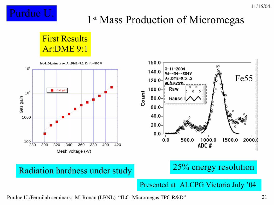
1st Mass Production of Micromegas
Radiation hardness under study
100
1000
104
105
280 300 320 340 360 380 400 420
feb4_04gaincurve, Ar:DME=9:1, Drift=-500 V
Gas gain
Gas
gai
n
Mesh voltage (-V)
First ResultsAr:DME 9:1
Fe55
Purdue U.
25% energy resolution
Presented at ALCPG Victoria July ’04

11/16/04
22Purdue U./Fermilab seminars: M. Ronan (LBNL) “ILC Micromegas TPC R&D”
Cosmic ray test stand
Superconducting magnet Data runs at 0.1, 0.3, 0.5, 0.7, 1, 1.5 & 2 Tesla
Trigger: 2-3 fold scintillator efficiency 10 – 50 % (lower at high fields)
Data acquisition: STAR FEE, VME readout w/ direct memory transfer (no selection, formatting, ...) overall improvement X20

11/16/04
23Purdue U./Fermilab seminars: M. Ronan (LBNL) “ILC Micromegas TPC R&D”
Online event displayRows 4 & 5 1 X 10 mm2

11/16/04
24Purdue U./Fermilab seminars: M. Ronan (LBNL) “ILC Micromegas TPC R&D”
Trigger simulation shows good understanding of angular distribution.
Simulation and analysis by Max. Chefdeville & Paul Colas, Saclay.

11/16/04
25Purdue U./Fermilab seminars: M. Ronan (LBNL) “ILC Micromegas TPC R&D”
LC-TPC gas choicesGases: Ar-CH
4 e.g. P10 – 90:10 %
Standard TPC gas, but some concern about neutron background sensitivity with hydrogen.
Ar-CO2
Slow gas, requiring larger drift fields.
Tesla TDR Gas (Ar-CH4-CO
2)
Chosen for the reference design to have less hydrogen at a lower drift field.
Ar-Isobutane e.g. 95:5 % High gains. Reasonably fast but larger diffusion.
Ar-CF4 e.g. 3-5 % CF
4
Very interesting! Very fast, no hydrogen.
ωτ ~20 @ B=4T transverse diffusion less than 200 m for drifts up to 1m.
However, need to worry about electron attachment and chemical reactions, e.g. aging.
Ar-CF4 Attachment / Amplification
Drift velocity
Ar-CF4: 5%
ED~0.2V/cm

11/16/04
26Purdue U./Fermilab seminars: M. Ronan (LBNL) “ILC Micromegas TPC R&D”
Data taking and processing
We took data with 3 different gases:
Ar-CF4:3% B = 0.1, 0.3, 0.5, 0.7, 1.0 T
Ar-CH4:10% B = 0.1, ..., 1.0, 1.5, 2 T (P10)
Ar-Isobutane: 5% B = 0.1, ..., 1.0, 1.5 T
High statistics runs were taken at B = 0.5T and 1T.
Data processing ran in parallel with data takingwriting zero-suppressed LCIO files and Java ntuples.We had online results like the plot shown comparingthe diffusion for different gases.
We're still developing the analysis and expectto learn more about Micromegas operation andcalibration in preparing final results.
Track width squared (mm2) as function of drift distance for ArCF4, ArCH4 and Ar-Isobutane gases at B = 1T.
B = 1 T

11/16/04
27Purdue U./Fermilab seminars: M. Ronan (LBNL) “ILC Micromegas TPC R&D”

11/16/04
28Purdue U./Fermilab seminars: M. Ronan (LBNL) “ILC Micromegas TPC R&D”
We found the chamber to have very uniform gain response, and the electronic noise to be quite low.
Plots are shown ofthe number of padsforming each clusterand of the summedamplitude signalsfor both 2X10 mm2
pad rows (#0,#1,#8 & #9)and the 1X10 mm2 padrows (#4 & #5).
2mm pads
1mm pads
2mm pads
1mm pads
Micromegas TPC Operation
ArCF4: 3%
@ B=1T
# pads hit
Pulse sums

11/16/04
29Purdue U./Fermilab seminars: M. Ronan (LBNL) “ILC Micromegas TPC R&D”
Gas Property Measurements● Drift velocity
We measure the drift velocity of different gases using the data itself. The longest drift time tracks observed are from tracks passing through the far end of the chamber, 50 cm from the readout plane.
● Electron attachment
Using the variation in the average energy deposition, measured by the truncated mean, with drift distance allows us to determine the electron attachment coefficient.
● Transverse diffusion
Measured through maximim likelihood fits to the distribution of signals on pads collecting ionization electrons from individual tracks. Relevant pads with no signals provide information as well.
● Magnetic field suppression
We measure the variation in the transverse diffusion as a function of the magnetic field to determine the suppression factor defined as (D
T[B]/D
T[0])-1/2 ~ τ.

11/16/04
30Purdue U./Fermilab seminars: M. Ronan (LBNL) “ILC Micromegas TPC R&D”
For Ar-CF4:3% we determine the drift velocity to be
vD = 8.8 +- 0.2 cm / microsec.
This corresponds to roughly 90 microns / nsec. So thatan overall track absolute z position measurement errorof about 100 microns yields track timing at 1 nsec level.
Drift time
# tracks
50 cm
Drift velocity measurements
We measure the drift velocity from the drifttime distribution of cosmic ray tracks as shown.
The trigger delay to the readout system andpedestal stabilization results in a loss ofinformation for short drift times. The far endof the chamber at roughly 50 cm begins to cutoff the distribution at about 100 clock ticksdepending on track dip angle. We take themax. drift time from the distribution to be105 +- 2 ticks.
We can also determine the drift velocityfrom individual tracks which are found to exitthe far end of the chamber.
In time we'll develop a full Monte Carlosimilation to improve the drift velocitydetermination.

11/16/04
31Purdue U./Fermilab seminars: M. Ronan (LBNL) “ILC Micromegas TPC R&D”
Comparisons to MagBoltz
4.184.24±0.08210Ar+5%iso
8.68.8±0.2200Ar+3%CF4
5.485.61±0.09150P10
4.384.43±0.0766P10
MagboltzVdrift
(cm/s)
E drift (V/cm)
Gas mixture

11/16/04
32Purdue U./Fermilab seminars: M. Ronan (LBNL) “ILC Micromegas TPC R&D”
Electron attachment measurements
We have not studied dE/dx informationvery carefully but have made a truncatedmean calculation using the lowest signalson 4 out of 6 pad rows.
Using the calculated TrMean we cancheck the attenuation length in ArCF4with our relatively long drift length.
We find that the attenuation length due to electron attachment in ArCF4 is larger than 4.4 m at 90% confidence.
ArCF4 B = 1T

11/16/04
33Purdue U./Fermilab seminars: M. Ronan (LBNL) “ILC Micromegas TPC R&D”
Transverse diffusion measurements
We determine the transverse diffusionfrom max. likelihood fits to individualanode pad signals on 6 pad rows(4 w/ 2mm pitch and 2 rows w/ 1mm pitch).The fitted track spread is used to measurethe transverse diffusion.
We find no evidence of any track angledependence in the measurement, shownbelow, as expected.
For Ar-CF4:3% at B = 1 Tesla, we measure in one analysis
DT = 68 +- 0.9 +- 3 microns / sqrt(cm)
This implies an expected transverse spread of about 360 microns after 2.5 m drift in a 3 Tesla magnetic field, and adiffusion limited point resolution of 60 microns for 6 mm pads.
B = 1T

11/16/04
34Purdue U./Fermilab seminars: M. Ronan (LBNL) “ILC Micromegas TPC R&D”
Ar CF4
Ar Isobutane Ar CH4 (P10)
Ar CH4 (P10)
(DT[B]/D
T[0])-1/2
B = 0.1T
B = 1.5T
B = 1T
B = 0.1T
B = 0.3T

11/16/04
35Purdue U./Fermilab seminars: M. Ronan (LBNL) “ILC Micromegas TPC R&D”
Measured Gas Properties
● Drift velocity First Micromegas TPC results @ B = 1T
We measure the drift velocities for the 3 gases being studied using the time distribution of cosmic ray tracks in our Micromegas TPC. We find at B = 1T
Ar-CF4: 3% vdrift
= 8.8 +- 0.2 (stat.) cm / µsec.
Ar-CH4: 10% vdrift
= 5.7 +- 0.1 (stat.) cm / µsec. ~ 10% systematic errors
Ar-Isobutane: 5% vdrift
= 4.4 +- 0.1 (stat.) cm / µsec.
Electron attachmentWe measure electron attachment by drift distance variation in the truncated mean.
Ar-CF4: 3% attachment
> 4.4 m @ 90% confidence
● Transverse diffusionWe measure the diffusion from maximum fits to the track ionization spread on pads in each row.
We find at B = 1T
Ar-CF4: 3% DT = 75 +- 2 (stat.) +- 7 (sys.) µm / sqrt(cm)
Ar-CH4: 10% DT = 100 +- 1.4 (stat.) +- 10 (sys.) µm / sqrt(cm)
Ar-Isobutane: 5% DT = 160 +- 1.0 (stat.) +- 16 (sys.) µm / sqrt(cm)

11/16/04
36Purdue U./Fermilab seminars: M. Ronan (LBNL) “ILC Micromegas TPC R&D”
● Detector response function. How to calibrate the detector and electronics ?
● Drift velocity endpoint determination.
● Diffusion measurements– Differences between Java/Fortran and with MagBoltz
– Zero track width measurements (thresholds, ...)
– Non-linearities in large diff. Measurements
– Fit range variations, diffusion offsets
– Fits to different drift time/distance bins
● dE/dx measurements
● Transverse position resolution
– Need to improve statistics in final analysis
● Pulse shaping
Systematics study

11/16/04
37Purdue U./Fermilab seminars: M. Ronan (LBNL) “ILC Micromegas TPC R&D”
ArCF4 B=1T ~
Track width^2 [mm^2]
Drift time [50 nsec ticks]

11/16/04
38Purdue U./Fermilab seminars: M. Ronan (LBNL) “ILC Micromegas TPC R&D”
B = 1.0T
Systematic Checks
Vary fit range

11/16/04
39Purdue U./Fermilab seminars: M. Ronan (LBNL) “ILC Micromegas TPC R&D”
End point determination

11/16/04
40Purdue U./Fermilab seminars: M. Ronan (LBNL) “ILC Micromegas TPC R&D”
ArCF4 B=1.0T

11/16/04
41Purdue U./Fermilab seminars: M. Ronan (LBNL) “ILC Micromegas TPC R&D”
SurpriseSurprise B=1 tesla
We observe a strong dependence of the total amplitude on the magnetic field.Not explained by relativistic rise of dE/dxElectronics? Mechanical effect on mesh?
0
100
200
300
400
500
600
0 0,5 1 1,5 2
Ar CF4
Ar Iso
Ar CH4
Magnetic field (T)
Ave
rage
am
plitu
de s
um
Apparent contradiction with previous measurements with a 55Fe source!
To be investigated…(harmless anyway)
Cosmic ray data
Presented by P. Colas atDurham ECFA meeting.

11/16/04
42Purdue U./Fermilab seminars: M. Ronan (LBNL) “ILC Micromegas TPC R&D”
● Gas gain
We obtained high gains (~5000) at modest mesh voltages, 300-350 V, except for ArCH4:10% (P10).
● Detector stability
Significant signal variation with magnetic field (larger at higher fields) was observd that is not understood at this time.
● Electronic noise
We operated the STAR front end electronics at very low noise levels (~1000 e's), typically 1-2 ADC counts.
● Point resolution measurement
We determine the point resolution by comparing the position measurements of the two center 1mm pad rows, correcting for track angles and for track fitting errors. The resolution measurements are binned in drift distance and fit with a linear dependence. We take the zero drift interept as the intrinsic Micromegas position resolution.
Micromegas TPC Performance
Note: We measure intrinsic (“zero-drift”) Micromegas resolutions of 60-100 microns, even with ArCH4 (P10) operating at low gain (~1000) as shown above.

11/16/04
43Purdue U./Fermilab seminars: M. Ronan (LBNL) “ILC Micromegas TPC R&D”
Transverse position resolution measurements
For near vertical tracks at small angles, we measure Micromegas intrinsic(“zero drift”) resolutions of roughly 60, 80 and 100 microns for Ar-CF4,Ar-CH4 and Ar-Isobutane gas mixtures, respectively.
We measure a large (X2) angular dependence of theresolution due to our elongated 1X10 mm2 anode pads.
We obtain position resolutions as small as60 - 80 microns for near vertical tracks usingour 1X10 mm2 pads.
B = 1T
B = 1T
Anode pads1X10 mm2
σ (µm)
σ (µm)
Distance [cm] (rad.)

11/16/04
44Purdue U./Fermilab seminars: M. Ronan (LBNL) “ILC Micromegas TPC R&D”
Micromegas pixel-TPC R&D
Rome IEEE Nuclear Science Symposium
●First GEM gas detector pixel readout R. Bellazini et al, Pisa
● NIKHEF / Saclay Micromegas Pixel TPC readout
●
New results fromNIKHEF / SaclayPixel-TPC Collaboration

11/16/04
45Purdue U./Fermilab seminars: M. Ronan (LBNL) “ILC Micromegas TPC R&D”

11/16/04
46Purdue U./Fermilab seminars: M. Ronan (LBNL) “ILC Micromegas TPC R&D”
Summary● Micro-pattern Gas Detectors (MPGD's) offer significant improvements
for future TPC applications, such as the ILC. An extensive R&D program is required to fully realize the benefits and to completely understand the limitations.
● A large-area Micromegas TPC has been operated successfully for a year with no significant problems.
● New high-precision gas property measurements have been made for three gases: ArCF4 3%, ArCH4 10% (P10) and Argon-Isobutane 5%.
● The Micromegas TPC performance measures are very exciting and improvements can be expected.
● Plans
– Continue analysis to learn how to calibrate, to understand systematics and to measure other properties such as dE/dx resolution and pulse time shaping.
– Future data taking is being planned for tests of charge spreading techniques, and for long operation in a reasonably intense beam.