
TiNi Ejector Release Mechanisms (ERM) TiNi Ejector Release ...

at SciVerse ScienceDirect
International Journal of Thermal Sciences xxx (2012) 1e13
Contents lists available
International Journal of Thermal Sciences
journal homepage: www.elsevier .com/locate/ i j ts
CFD simulation on the effect of primary nozzle geometries for a steam ejectorin refrigeration cycle
Natthawut Ruangtrakoon a, Tongchana Thongtip a, Satha Aphornratana a,*, Thanarath Sriveerakul b
a Sirindhorn International Institute of Technology, Thammasat University, PO Box 22, Thammasat Rangsit Post Office, Patumthani 12121, ThailandbDepartment of Mechanical Engineering, Ubon Ratchathani University, Ubonratchathani 34190, Thailand
a r t i c l e i n f o
Article history:Received 8 December 2011Received in revised form23 July 2012Accepted 23 July 2012Available online xxx
Keywords:EjectorJet refrigerationJet coolingCFDPrimary nozzle
* Corresponding author. Tel.: þ662 9869009x2203;E-mail address: [email protected] (S. Aphornratan
1290-0729/$ e see front matter � 2012 Elsevier Mashttp://dx.doi.org/10.1016/j.ijthermalsci.2012.07.009
Please cite this article in press as: N. Ruangrefrigeration cycle, International Journal of T
a b s t r a c t
In this study, the CFD technique was employed to investigate the effect of the primary nozzle geometrieson the performance of an ejector used in the steam jet refrigeration cycle. In all cases, only one fixed-geometry mixing chamber together with eight different primary nozzles was investigated numericallyusing the commercial CFD package, FLUENT 6.3. The effects on the primary fluid pressure, mass flow rateand Mach number were observed and analyzed. The Mach number contour lines were used to explainthe mixing process occurring inside the ejector. It was found that shock’s position of the mixed fluid andthe expansion angle of the primary fluid jet stream within the mixing chamber played a very importantrole in the ejector performance.
� 2012 Elsevier Masson SAS. All rights reserved.
1. Introduction
A steam jet refrigeration system is an interesting heat-poweredrefrigeration system due to its environmental friendly operatingcharacter. It can convert waste heat (low-grade thermal energy)that is rejected from many industrial processes to useful refriger-ation, thereby reducing the electrical energy consumption of theair-conditioning system. Another advantage is that water, the mostenvironmental friendly substance, can be used as the working fluidin the system. Over the past decades, many researchers have triedto improve the steam jet refrigeration system. Some researchersinvestigated the effect of operating conditions on the systemperformance [1e6].
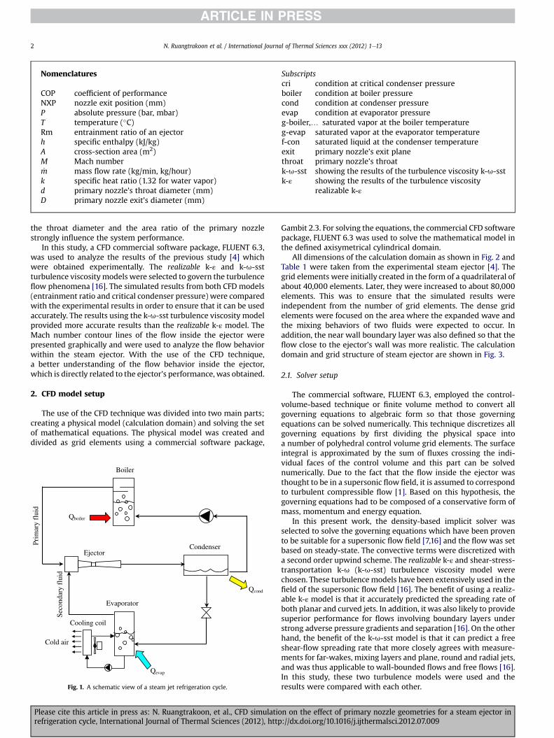
Fig. 1 presents a schematic view of a steam ejector refrigerationsystem. The high pressure and high temperature saturated steam isproduced in the boiler and it is used as the primary fluid for theejector. The ejector draws low pressure water vapor from theevaporator as its secondary fluid. This causes thewater to evaporateat low pressure and produce the refrigeration effect. The ejectordischarges its exhaust to the condenserwhere it is condensed at theambient temperature. Some of the liquid is pumped back to theboiler while the remainder is returned to the evaporator.
fax: þ662 9869009x2201.a).
son SAS. All rights reserved.
trakoon, et al., CFD simulatiohermal Sciences (2012), http
Performance of the steam jet refrigeration is defined in terms of thecoefficient of performance (COP):
COP ¼ Rm$hg�evap � hf�conhg�boiler � hf�con
(1)
where Rm is defined as the entrainment ratio of the ejector:
Rm ¼ mass flow of the secondary fluidmass flow of the primary fluid
(2)
Since the enthalpy change at the boiler is not much differentfrom the enthalpy change at the evaporator, it can be assumed thatCOPzRm.
Computational fluid dynamics (CFD) can be used to explain thephenomenon inside the ejector. CFD’s results available in theliterature [7e15] were found to agree well with experimentalvalues. Therefore, the CFD technique can be used to accuratelypredict the performance of the steam jet refrigeration system.
In past research paper [4], effects of the primary nozzle’sgeometries and the operating conditions on the ejector perfor-mance were analyzed experimentally. The steam ejectors as shownin Fig. 2 were tested with eight different primary nozzles. Alldimensions of primary nozzles are presented in Table 1. The boilertemperatures were varied in the range of 110e150 �C. Theevaporator temperature was fixed at 7.5 �C. The tests showed that
n on the effect of primary nozzle geometries for a steam ejector in://dx.doi.org/10.1016/j.ijthermalsci.2012.07.009
Nomenclatures
COP coefficient of performanceNXP nozzle exit position (mm)P absolute pressure (bar, mbar)T temperature (�C)Rm entrainment ratio of an ejectorh specific enthalpy (kJ/kg)A cross-section area (m2)M Mach number_m mass flow rate (kg/min, kg/hour)k specific heat ratio (1.32 for water vapor)d primary nozzle’s throat diameter (mm)D primary nozzle exit’s diameter (mm)
Subscriptscri condition at critical condenser pressureboiler condition at boiler pressurecond condition at condenser pressureevap condition at evaporator pressureg-boiler,. saturated vapor at the boiler temperatureg-evap saturated vapor at the evaporator temperaturef-con saturated liquid at the condenser temperatureexit primary nozzle’s exit planethroat primary nozzle’s throatk-u-sst showing the results of the turbulence viscosity k-u-sstk-ε showing the results of the turbulence viscosity
realizable k-ε
N. Ruangtrakoon et al. / International Journal of Thermal Sciences xxx (2012) 1e132
the throat diameter and the area ratio of the primary nozzlestrongly influence the system performance.
In this study, a CFD commercial software package, FLUENT 6.3,was used to analyze the results of the previous study [4] whichwere obtained experimentally. The realizable k-ε and k-u-sstturbulence viscositymodels were selected to govern the turbulenceflow phenomena [16]. The simulated results from both CFD models(entrainment ratio and critical condenser pressure) were comparedwith the experimental results in order to ensure that it can be usedaccurately. The results using the k-u-sst turbulence viscosity modelprovided more accurate results than the realizable k-ε model. TheMach number contour lines of the flow inside the ejector werepresented graphically and were used to analyze the flow behaviorwithin the steam ejector. With the use of the CFD technique,a better understanding of the flow behavior inside the ejector,which is directly related to the ejector’s performance, was obtained.
2. CFD model setup
The use of the CFD technique was divided into two main parts;creating a physical model (calculation domain) and solving the setof mathematical equations. The physical model was created anddivided as grid elements using a commercial software package,
Qevap
Qcond
Prim
ary
flui
d
Seco
ndar
y fl
uid
Ejector
Evaporator
Qboiler
Boiler
Condenser
Cooling coil
Cold air
Fig. 1. A schematic view of a steam jet refrigeration cycle.
Please cite this article in press as: N. Ruangtrakoon, et al., CFD simulatiorefrigeration cycle, International Journal of Thermal Sciences (2012), http
Gambit 2.3. For solving the equations, the commercial CFD softwarepackage, FLUENT 6.3 was used to solve the mathematical model inthe defined axisymetrical cylindrical domain.
All dimensions of the calculation domain as shown in Fig. 2 andTable 1 were taken from the experimental steam ejector [4]. Thegrid elements were initially created in the form of a quadrilateral ofabout 40,000 elements. Later, they were increased to about 80,000elements. This was to ensure that the simulated results wereindependent from the number of grid elements. The dense gridelements were focused on the area where the expanded wave andthe mixing behaviors of two fluids were expected to occur. Inaddition, the near wall boundary layer was also defined so that theflow close to the ejector’s wall was more realistic. The calculationdomain and grid structure of steam ejector are shown in Fig. 3.
2.1. Solver setup
The commercial software, FLUENT 6.3, employed the control-volume-based technique or finite volume method to convert allgoverning equations to algebraic form so that those governingequations can be solved numerically. This technique discretizes allgoverning equations by first dividing the physical space intoa number of polyhedral control volume grid elements. The surfaceintegral is approximated by the sum of fluxes crossing the indi-vidual faces of the control volume and this part can be solvednumerically. Due to the fact that the flow inside the ejector wasthought to be in a supersonic flow field, it is assumed to correspondto turbulent compressible flow [1]. Based on this hypothesis, thegoverning equations had to be composed of a conservative form ofmass, momentum and energy equation.
In this present work, the density-based implicit solver wasselected to solve the governing equations which have been provento be suitable for a supersonic flow field [7,16] and the flow was setbased on steady-state. The convective terms were discretized witha second order upwind scheme. The realizable k-ε and shear-stress-transportation k-u (k-u-sst) turbulence viscosity model werechosen. These turbulence models have been extensively used in thefield of the supersonic flow field [16]. The benefit of using a realiz-able k-ε model is that it accurately predicted the spreading rate ofboth planar and curved jets. In addition, it was also likely to providesuperior performance for flows involving boundary layers understrong adverse pressure gradients and separation [16]. On the otherhand, the benefit of the k-u-sst model is that it can predict a freeshear-flow spreading rate that more closely agrees with measure-ments for far-wakes, mixing layers and plane, round and radial jets,and was thus applicable to wall-bounded flows and free flows [16].In this study, these two turbulence models were used and theresults were compared with each other.
n on the effect of primary nozzle geometries for a steam ejector in://dx.doi.org/10.1016/j.ijthermalsci.2012.07.009

Fig. 2. The steam ejector used in the research study.
N. Ruangtrakoon et al. / International Journal of Thermal Sciences xxx (2012) 1e13 3
The flow close to the ejector’s wall (near wall treatment) gov-erned by the realizable k-εmodel was essentially defined in order toobtain the realistic flowclose to the ejector’s wall. The optional nearwall treatment, standard-wall-function, was used in this work. Thesimulated results obtained from standard-wall-function areacceptable when compared with the experimental results deter-mined by pressures along the length of an ejector. However, the k-u-sst turbulence model is not defined near the wall [7,8]. This isbecause its mathematical model had already emphasized on theflow close the ejector’s wall.
2.2. Boundary condition and working fluid properties
The upstream boundary conditions of the ejector, the primaryfluid inlet and the secondary fluid inlet were set as pressure-inlettype. Meanwhile, the pressure-outlet type was applied to thedownstream of the steam ejector (mixed fluid outlet).
All wall surfaces of the steam ejector were set as the adiabaticwalls. In other words, the heat loss at all wall surfaces of the steamejector was neglected since it had less impact on the solution [2].
Water vapor, the working fluid used, was assumed to be an idealgas because the steam ejector was extensively operating at a rela-tively low absolute pressure inside the mixing chamber. In thissituation, the behavior of the real gas was close to the ideal gas.Therefore, the ideal gas assumption is acceptable. The properties ofsaturated steam used during the simulation are tabulated inTable 2.
2.3. Convergence criteria and results
The solution is considered as convergedwhen the two followingconverging criteria were satisfied. Firstly, it had to be shown thatthe mass fluxes across each face in the calculation domain arestable (In this study, the difference of mass flow rates at the inletand at the outlet passing through the modeled ejector were less
Table 1The dimensions of primary nozzles.
Nozzle code d (mm) (D:d)2 Calculated exitMach number
Ejector’s area ratio
d1.4 M4 1.4 20:1 4.0 184:1d1.7 M4 1.7 124:1d2.0 M4 2.0 90:1d2.3 M4 2.3 68:1d2.4 M4 2.4 62:1d2.6 M4 2.6 53:1d1.4 M3 1.4 7:1 3.0 184:1d1.4 M5.5 1.4 88:1 5.5
Remark: Ejector area ratio ¼ (ejector throat’s diameter/primary nozzle throat’sdiameter)2.
Please cite this article in press as: N. Ruangtrakoon, et al., CFD simulatiorefrigeration cycle, International Journal of Thermal Sciences (2012), http
than 10�7 kg/s). Secondly, every residual of the calculation must belower than the specified value (in this case, less than 10�6 after100,000 iterations) in order to ensure that the solution from thesimulation is accurate.
The evaluation of the mass flow rate entering the primarynozzle (primary fluid mass flow rate) and leaving the evaporator tothe mixing chamber (secondary fluid mass flow rate) is alsointroduced to calculate the entrainment ratio which is the ejector’sperformance indicator.
3. Validation with experimental results
Table 3 provides the significant results of entrainment (Rm) andcritical condenser pressure (Pcri). This table shows the comparisonof the simulated results and the experimental results obtainedpreviously [4]. It is seen that the simulated results are very similarto the experimental results. In all cases, the values of the simulatedentrainment ratio were higher (for example, in the case of using theprimary nozzle with the throat diameter of 1.7 mm operating withthe boiler temperature of 140 �C, 0.29 for the simulated result and0.32 for the experimental result) while the values of the simulatedcritical condenser pressure (the highest possible discharge pres-sure) were lower than the actual values (for example, 45 mbar forthe simulated result and 44 mbar for the experimental result). Itwas also found that the simulated results based on k-u-sst turbu-lence viscosity model more closely corresponded to the experi-mental values than those based on the realizable k-ε turbulenceviscosity model.
Possible explanations for these discrepancies may be thefollowing three reasons. Firstly, the working fluid was assumed tobe an ideal gas. In the actual process, even though the pressure inthe mixing chamber of the ejector is very low, the fluid is very closeto saturation condition. Therefore, the assumption of an ideal gasmay not be perfectly correct. However, the assumption of the idealgas was selected in order to avoid the difficulty in themathematicalmodel. Secondly, the simulation assumes an adiabatic wall. Thismeans that there is no heat transfer across the mixing chamber’swall-boundary. However, it is impossible to avoid the heat transferbetween the tested ejector and the surroundings. Thirdly, thecondition at the wall surface of the assumed ejector cannot bedefined exactly. In the CFD model, a smooth-wall was assumed.However, such a smooth-wall cannot be achieved in practice.Moreover, the primary nozzles may not have been manufacturedcorrectly since they are very small.
Regarding the simulated results as shown in Table 3 based onthe realizable k-ε and k-u-sst turbulence models, it was found thatthe k-u-sst viscosity model provided more accurate results thanthose from the realizable k-ε viscosity model. This was observedwhen the ejector was operated at a relatively high boiler
n on the effect of primary nozzle geometries for a steam ejector in://dx.doi.org/10.1016/j.ijthermalsci.2012.07.009

Fig. 3. Calculation domain and grid structure of the ejector’s model.
N. Ruangtrakoon et al. / International Journal of Thermal Sciences xxx (2012) 1e134
temperature (higher than 140 �C). A possible reason is that the k-u-sst viscosity model emphasizes free shear flow for far wakes andthe mixing layer, unlike in the case of realizable k-ε viscosity model.Moreover, for a very strong adverse pressure gradient, the realizablek-εmodel is unable to accurately predict the ejector’s performance.Therefore, the Mach number contour lines obtained from the k-u-sst turbulent viscosity model were used to analyze the flowbehavior within the steam ejector in this study.
4. CFD results and discussion
4.1. Flow and mixing process within ejector
The Mach number contour lines obtained from the CFD simu-lation are presented in Fig. 4. The boiler saturation temperaturewasset at 130 �C, the evaporator saturation was set at 7.5 �C, and thecondenser saturation pressure was 30 mbar. The primary nozzlewas d2.0 M4. This nozzle had a throat diameter of 2.0 mm andproduced an exit Mach number of 4.0.
From Fig. 4, it can be seen that as a high temperature and highpressure fluid known as “primary fluid” enters the primary nozzle,the fluid is accelerated in the converging portion of the primarynozzle (1). At the nozzle throat, the Mach number is unity and theflow is choked. The flow is further accelerated to supersonic level inthe diverging part of the nozzle (2). At the nozzle’s exit plane, theprimary fluid leaves the primary nozzle as a supersonic stream(M z 4.00) which flows under the free boundary pressure condi-tion. This results in the expandedwave [18] to be formedwith somevalue of expansion angle. The expanded wave can be classified intotwo categories: an under-expanded wave and an over-expandedwave which are presented in Fig. 5.
Table 2The working fluid properties.
Properties Value
Viscosity, (kg/m s) 1.34 � 10�5
Thermal conductivity, (W/m k) 0.0261Specific heat, (J/kg K) 2014.00Molecular weight, (kg/kmol) 18.01534
Please cite this article in press as: N. Ruangtrakoon, et al., CFD simulatiorefrigeration cycle, International Journal of Thermal Sciences (2012), http
In the case of an under-expanded wave, the primary stream willleave the primary nozzle with divergence of expansion angle asshown in Fig. 5(A). This case occurs when the nozzle’s exit pressureis greater than the mixing chamber pressure [8,18]. The effect of anunder-expanded wave results in the jet stream being furtherexpanded after leaving the nozzle’s exit plane and achievinga higher supersonic level. This causes a diamondwave (3) to appear.The expansion angle and the supersonic level are dependent on thedifferential pressure between the pressure at the nozzle exit planeand that in the mixing chamber [18].
In the case of an over-expanded wave, the primary stream willleave the primary nozzle with convergence of expansion angle asshown in Fig. 5(B). This case occurs when the static pressure at theprimary nozzle’s exit plane is lower than that in the mixingchamber [18]. Similar to the case of the under-expanded wave, theseries of oblique shock and a diamondwave are produced. However,the oblique shock is not as strong as that for the case of an under-expanded wave. Therefore, the flow of the jet stream is moreuniformwhich can be observed by the fact that the supersonic levelof the jet stream after leaving the nozzle is almost unchanged.These cause the total loss of the jet stream’s momentum to be lessthan that for the case of an under-expanded wave. This is moredesirable to the ejector’s performance. For this particular study, theover-expanded wave usually occurs when the ejector is operatedwith a relative high Mach number (M > 4.00) as shown in Fig. 5B.
Referring to Fig. 4, the oblique shock found in the expandedwave may be called the 1st series of oblique shock or the 1st shock(4). It can be observed that the flow form is a semi-separationbetween the primary and secondary fluids which maintains thestatic pressure across the free boundary between the primary jetcore and the surrounding fluid. These fluids are not immediatelymixed. Therefore, the converging duct (5) for entraining thesecondary fluid is formed by the primary fluid jet core and themixing chamber’s wall [8]. At the interface of the primary fluid jetcore and the secondary fluid, due to the large velocity difference,the shear stress layer (6) is created. This causes the secondary fluidto accelerate to sonic velocity and choke at some section along thisconverging duct. The annular area formed by the primary jet coreand the mixing chamber wall where the secondary fluid chokes iscalled an effective area (Ae) (7).
n on the effect of primary nozzle geometries for a steam ejector in://dx.doi.org/10.1016/j.ijthermalsci.2012.07.009

Table 3Experimental and CFD results.
Nozzle Tboiler (�C) Rmexp Rmk-u-sst Rmk-ε Errora, Rm Pcri (mbar) Pcri, k-u-sst (mbar) Pcri, k-ε (mbar) Errorb, Pcri
k-u-sst (%) k-ε (%) k-u-sst (%) k-ε (%)
d1.7M4 130 0.422 0.446 0.464 5.687 9.953 35.0 33.5 32.5 4.286 7.143140 0.287 0.316 0.351 10.105 22.230 45.0 44.0 42.0 2.222 6.667150 0.188 0.210 0.273 11.702 45.213 58.5 55.0 55.0 5.983 5.983
d1.4M4 150 0.288 0.322 0.370 11.806 28.427 44.0 42.0 37.0 4.545 15.909d1.7M4 0.188 0.210 0.273 11.702 45.213 58.5 55.0 55.0 5.983 5.983d2.0M4 0.102 0.125 0.171 22.549 67.647 79.0 73.0 75.0 7.595 5.063d1.4M3 150 0.282 0.315 0.373 11.702 32.270 38.0 37.0 30.0 2.632 21.053d1.4M4 0.288 0.322 0.370 11.806 28.472 44.0 42.0 37.0 4.545 15.909d1.4M5.5 0.280 0.317 0.362 13.214 29.286 54.0 46.0 40.0 14.815 25.926d1.4M4 150 0.288 0.322 0.370 11.806 28.427 44.0 41.0 37.0 6.818 15.909d1.7M4 140 0.287 0.316 0.351 10.105 22.230 44.5 42.0 38.0 5.618 14.607d2.0M4 130 0.286 0.312 0.320 9.091 11.888 45.0 42.5 40.0 5.556 11.111d2.3M4 120 0.273 0.311 0.314 13.919 15.018 51.0 45.0 41.0 11.768 19.608d2.4M4 113.6 0.267 0.308 0.315 16.854 17.978 49.5 43.0 40.0 13.131 19.191d2.6M4 111.2 0.262 0.304 0.312 16.031 19.084 48.5 42.0 40.0 13.402 17.526
All results were obtained and simulated at an evaporator saturation temperature of 7.5 �C and NXP ¼ þ23 mm.(The NXP (Nozzle Exit Position) was defined as the distance between the primary nozzle exit plane and the mixing chamber inlet planes as shown in Fig. 2).
a Error (%) ¼ 100 � (CFD’s entrainment ratio�Experiment’s entrainment ratio)/Experiment’s entrainment ratio.b Error (%) ¼ 100 � (CFD’s critical pressure�Experiment’s critical pressure)/Experiment’s critical pressure.
N. Ruangtrakoon et al. / International Journal of Thermal Sciences xxx (2012) 1e13 5
Upstream of the effective area (Ae), where the two fluids comeinto contact for the first time, a small amount of the secondary fluidis gradually mixed with the primary fluid. The remainder will bemixed after the secondary flow reaches the sonic level or chokes.The effective area can occur at any cross-section along the mixingchamber and it is difficult to specify its exact location because itdepends on the operating-pressure and geometries of the ejector.
During the mixing process, momentum of the primary fluid istransferred to the secondary fluid. Thus, the primary stream isgradually retarded which can be observed by the gradual disap-pearance of a diamond wave. Meanwhile, the secondary stream isgradually accelerated. As the mixed stream flows pass through theconstant area section, due to the high downstream pressure,a series of oblique shocks are induced (8) as shown in Fig. 4. Theseshocks are called 2nd series of oblique shock or 2nd shock. In thispaper, the 2nd shock’s position is the location where the 2nd shockis first produced. As a result of this series of oblique shock, the staticpressure of the mixed fluid is increased rapidly. The flow form ischanged from supersonic to subsonic. In the subsonic diffusersection, the mixed flow is further slowed down to almost stagna-tion in order to recover the static pressure before discharging to thecondenser.
4.2. Effect of the condenser pressure
To establish the effect of the condenser pressure, the boilersaturation temperature was 150 �C and the evaporator saturationwas 7.5 �C. The condenser pressure was varied between 30 mbar to
Fig. 4. Mach number contour lines in the steam ejector using the primary nozzle d2.0M4 forof 30 mbar.
Please cite this article in press as: N. Ruangtrakoon, et al., CFD simulatiorefrigeration cycle, International Journal of Thermal Sciences (2012), http
the value at which the ejector failed to operate. The used primarynozzle was d1.4 M4.
Performance of the ejector is presented as variation of theentrainment ratio influenced by downstream pressure (condenserpressure), called a performance curve. An example of the perfor-mance curve based on the CFD technique is shown in Fig. 6. Theperformance curve is divided into three operating regions: chokedflow region, unchoked region flow, and reversed flow region.Choked flow and unchoked flow regions are separated by “criticalcondenser pressure”, and unchoked flow and reversed flow regionsare separated by “breakdown pressure”.
Fig. 7 shows the Mach number contour lines representing theflow in the steam ejector. It can be seen that an increase in thecondenser pressure from A to D of 30e47 mbar causes the 2ndshock position to move backward into the constant area throatsection. However, if the back pressure does not exceed the criticalvalue or operates in the choked flow region (A and B) the shockwill not affect the mixing behavior of the two fluid streams. Thesecondary fluid is still choked at the effective area. This results ina constant entrainment ratio with condenser pressure varied.
If the condenser pressure is higher than the critical value oroperates in the unchoked flow region (C), the 2nd shock will movecloser to the region where the mixing process occurs. In this case,the mixing process is disturbed by the shock. As a result, thesecondary fluid is no longer choked in the mixing chamber. Thus,less amount of the secondary fluid is drawn. This causes theentrainment ratio to drop sharply when the condenser pressure isincreased further.
boiler temperature of 130 �C, evaporator temperature of 7.5 �C and condenser pressure
n on the effect of primary nozzle geometries for a steam ejector in://dx.doi.org/10.1016/j.ijthermalsci.2012.07.009

Fig. 5. Forms of primary fluid’s expansion wave at the nozzle exit.
N. Ruangtrakoon et al. / International Journal of Thermal Sciences xxx (2012) 1e136
If the back pressure is increased higher than the breakdownvalue or the ejector is in the reversed flow region (D), it can be seenthat the 2nd shock position will move toward the primary nozzle.Its effect will disturb the primary fluid jet stream until theexpanded wave cannot be produced. The primary jet stream isforced back to the entrance of the secondary fluid. This results inthe hot primary fluid from the boiler flowing back to the evaporator
Fig. 6. Effect of operating pressures on performance of a steam jet refrigeratorobtained from CFD simulation for a boiler temperature of 150 �C and an evaporatortemperature of 7.5 �C.
Please cite this article in press as: N. Ruangtrakoon, et al., CFD simulatiorefrigeration cycle, International Journal of Thermal Sciences (2012), http
which causes the ejector to be malfunction and the entrainmentratio will drop to zero.
4.3. Effect of the primary fluid pressure
To establish this effect, the primary nozzle d1.7M4 with thethroat diameter 1.7 mm and exit Mach number of 4.0 was used. Theboiler saturation temperatures were ranged from 130 to 150 �C. Theevaporator saturation temperature was fixed at 7.5 �C.
Fig. 8 shows the effect of the boiler saturation temperature on theejector performance based on the CFD technique. The figure showsthe Mach number contour lines which represent the flow inside theejector for the points A, B, and C at the same condenser pressure of30 mbar. It is shown that, when the boiler saturation temperature isincreased, the ejector can be operated at a higher critical condenserpressure. However, this condition comes together with a decrease inthe entrainment ratio. These effects can be explained clearly by theMach number contour lines as shown in Fig. 9.
From Fig. 9, it can be seen that when the boiler saturationtemperature is increased, an expanded-wave appearing in themixing chamber is formed with a larger expansion angle since theprimary jet stream flows with a higher momentum. In this case,a narrower converging duct and a smaller effective area aresimultaneously produced. Therefore, less amount of the secondary
n on the effect of primary nozzle geometries for a steam ejector in://dx.doi.org/10.1016/j.ijthermalsci.2012.07.009

Fig. 7. Variation of the contour of Mach number for various condenser pressures.
N. Ruangtrakoon et al. / International Journal of Thermal Sciences xxx (2012) 1e13 7
flow rate is drawn into the mixing chamber. That means, when theboiler saturation temperature is increased, the ejector entrains lesssecondary fluid while the primary fluid mass flow rate is increased.The overall result is a reduction in the entrainment ratio. In addi-tion, it was also found that the flow with a higher jet streammomentum results in the further expansion of the jet stream afterleaving from the primary nozzle. This causes a diamond wave toshock and to achieve the higher Mach number at the 1st shock.
0
0.2
0.4
0.6
0.8
20 40Condenser P
Rm
(Ent
rain
men
t Rat
io)
Tempera
20 26 32
A
B
C
Fig. 8. The variation of the entrainment ratio with the pr
Please cite this article in press as: N. Ruangtrakoon, et al., CFD simulatiorefrigeration cycle, International Journal of Thermal Sciences (2012), http
However, the same value of Mach number is produced at the nozzleexit plane. This agrees well with the principle of compressible flowtheory; the primary nozzle exit Mach number for a converging-diverging nozzle depends on the area ratio of the primary nozzlethroat diameter to the primary nozzle exit diameter [18]. This alsoagrees with the experimental result given by Ruangtrakoon et al.[4]. The minimum suction pressure of the ejector is almost inde-pendent from the boiler saturation temperature which also implies
60 80 100ressure (mbar)
Boiler = 130°C
Boiler = 140°C
Boiler = 150°C
ture (°C)
38 44 45
d1.7 M4 , Tevap = 7.5 °C
Tboiler = 130 C
Tboiler = 140 C
Tboiler = 150 C
imary fluid pressure obtained from CFD simulation.
n on the effect of primary nozzle geometries for a steam ejector in://dx.doi.org/10.1016/j.ijthermalsci.2012.07.009

Fig. 9. Variation of the contour of Mach number for various primary fluid pressures.
N. Ruangtrakoon et al. / International Journal of Thermal Sciences xxx (2012) 1e138
that the nozzle’s exit pressure is independent of boiler pressure.Since the primary fluid jet stream flows with a higher momentum(due to the larger amount of the primary mass flow rate), the 2ndshock moves forward to the subsonic diffuser due to an increase inthe total momentum of the mixed stream. As a result, the ejector isable to operate at a higher critical condenser pressure.
0
0.2
0.4
0.6
0.8
20 40 60 80 100Condenser Pressure (mbar)
Rm
(Ent
rain
men
t Rat
io)
D1.4 M4 D1.7 M4 D2.0 M4
Temperature (°C)
20 26 32 38 44 45
Tboiler = 150 °C , Tevap = 7.5 °C
A
B
C
d d1.7 M4 d
Fig. 10. The variation of the entrainment ratio with the nozzle’s throat diameterobtained from CFD simulation.
4.4. Effect of the nozzle’s throat diameter with fixed upstreamconditions
In this case, the upstream conditions, boiler and the evaporatorsaturation temperatures were fixed at 150 �C and 7.5 �C, respec-tively. Three primary nozzles, d1.4M4, d1.7M4, and d2.0M4, with anidentical area ratio of 20:1 were used. Therefore, they producedequal exit Mach number of 4.0. Fig. 10 shows the effects of theprimary nozzle’s throat diameter on the ejector performance basedon the CFD technique. Fig. 11 shows the Mach number contour lineswhich represent the flow behavior inside the ejector under theconditions of points A, B, and C with the same condenser pressureof 30 mbar.
From Fig. 10 it can be seen that when the larger primary nozzle’sthroat diameter is used, the ejector can be operated at a highercritical condenser pressure, while the entrainment ratio is reduced.In other words, this effect is similar to the case of an increase inboiler saturation pressure. This is because at a fixed boiler pressure,the primary nozzle with a larger throat diameter provides a largeramount of the primary fluid mass flow rate. As a result, the primarystream will flow with a higher momentum. Fig. 11 also shows thatlarger expansion angle of an expanded-wave is produced when theprimary nozzle with a larger throat diameter is investigated. Anarrower converging duct and a smaller effective area for thesecondary fluid are the results. The further expansion of jet streamoccurred after leaving the nozzle whilst the same Mach number isproduced at the nozzle’s exit due to an identical area ratio. Such
Please cite this article in press as: N. Ruangtrakoon, et al., CFD simulatiorefrigeration cycle, International Journal of Thermal Sciences (2012), http
effects are a consequence of the flow with a higher momentum.When the larger primary nozzle throat diameter is used, lessamount of secondary fluid is drawn into the mixing chamber andthe reduction of the entrainment ratio is the result. However, theejector can be operated at a higher critical condenser pressure ascan be seen by the 2nd shock’s position being moved toward thediffuser exit as shown in Fig. 11.
4.5. Effect of the nozzle’s exit Mach number
In this case, three primary nozzles, d1.4M3, d1.4M4, andd1.4M5.5 were used. The boiler saturation temperature and evap-orator saturation temperature were fixed at 150 �C and 7.5 �C,respectively. All nozzles had equal throat diameter of 1.4 mm inorder to produce the same critical mass flow rate. They had an area
n on the effect of primary nozzle geometries for a steam ejector in://dx.doi.org/10.1016/j.ijthermalsci.2012.07.009

Fig. 11. Variation of contour of Mach number for various nozzle’s throat diameters.
N. Ruangtrakoon et al. / International Journal of Thermal Sciences xxx (2012) 1e13 9
ratio of 7:1, 20:1, and 88:1 which produced the exit Mach numbersof 3.0, 4.0, and 5.5, respectively.
Fig. 12 shows effects of the nozzle’s exit Mach number on theperformance curve and Fig. 14 shows the Mach number contourlines which represent the flow within the steam ejector at thecondenser pressure of 30 mbar under the conditions of points A, B,and C.
Fig. 12 shows that the increase of Mach number at the nozzle’sexit plane causes the ejector to be able to operate at a higher criticalcondenser pressure. It also shows that the entrainment ratio inchoked flow mode remains constant and is independent from thevariation of nozzle’s exit Mach number.
The momentum of the primary stream is increased with thenozzle’s exit Mach number (they provide the same amount ofprimary fluid flow rate). This results in the 2nd shock movingforward to a subsonic diffuser as can be seen from Fig. 12. The
0
0.2
0.4
0.6
0.8
20 40 60 80 100Condenser Pressure (mbar)
Rm
(Ent
rain
men
t Rat
io)
D1.4 M3 D1.4 M4 D1.4 M5.5
Tboiler = 150 °C , Tevap = 7.5 °C
Temperature (°C)
20 26 32 38 44 45
A,B,C
d d d
Fig. 12. The variation of the entrainment ratio with the nozzle’s exit Mach numberobtained from CFD simulation.
Please cite this article in press as: N. Ruangtrakoon, et al., CFD simulatiorefrigeration cycle, International Journal of Thermal Sciences (2012), http
ejector can be operated at a higher critical condenser pressurewhen the nozzle with greater Mach number is used.
The overall result described above implies that the primarynozzle with a relatively high Mach number is more desirable.However, from Fig. 13, it can be seen that the nozzle with a higherMach number is limited by the nozzle’s exit diameter and theminimum boiler pressure as tabulated in Table 4. The large nozzle’sexit diameter will obstruct the entrance of secondary flow.However, it is efficiently compensated for a larger effective area andlarger converging duct as shown in Fig. 13. The nozzle with high exitMach number provides a relatively lower exit pressure. This resultsin the transformation of an under-expanded wave to an over-expanded wave (when increasing the exit Mach number from 3.0to 5.5).
If a primary nozzle with exit Mach number of 6 is used, thenozzle’s exit diameter of 16 mm is required as shown in Table 4.This is as large as the mixing chamber throat diameter (19 mm).This will block the secondary flow at the mixing chamber inlet.Moreover, the essentially required minimum boiler pressure isincreased as shown in Table 4. Therefore, in practice, the primarynozzle should be designed so that the exit Mach number is between4.0 and 5.5 [4],.
From Table 3, the nozzle’s area ratios were obtained fromequation (3) and the expansion ratios were calculated from equa-tion (4):
AexitAthroat
¼ 1Mexit
���
2kþ 1
���1þ
��k� 12
��M2
exit
��� kþ12ðk�1Þ
(3)
PboilerPexit
¼�1þ
�k� 12
��M2
exit
� kk�1
(4)
n on the effect of primary nozzle geometries for a steam ejector in://dx.doi.org/10.1016/j.ijthermalsci.2012.07.009

Fig. 13. Variation of contour of Mach number for various nozzles’ exit Mach number.
0
0.2
0.4
0.6
0.8
20 40 60 80 100
Condenser Pressure (mbar)
Rm
(Ent
rain
men
t Rat
io)
D1.4 M4 , Boiler=150°CD1.7 M4 , Boiler=140°CD2.0 M4 , Boiler=130°CD2.3 M4 , Boiler=120°CD2.4 M4 , Boiler=114°CD2.6 M4 , Boiler=111.2°C
Temperature (°C)
20 26 32 38 44 45
(A) (B) (C) (D) (E) (F)
Evap = 7.5 °C
d1.4 M4, Tboiler = 150°C (A) d1.7 M4, Tboiler = 140°C (B) d2.0 M4, Tboiler = 130°C (C) d2.3 M4, Tboiler = 120°C (D) d2.4 M4, Tboiler = 114°C d2.6 M4, Tboiler = 111.2°C (E) Tevap = 7.5°C
Fig. 14. The variation of the entrainment ratio for different nozzles at constant criticalmass flow rate and the exit Mach number obtained from CFD simulation.
Table 5Boiler temperature and critical mass flow rate.
Nozzle Boiler temperature (�C) Critical mass flow (kg/hour)
Experiment CFD
d1.4M4 150.0 4.568 4.691d1.7M4 140.0 4.625 4.710d2.0M4 130.0 4.537 4.722d2.3M4 120.0 4.530 4.701d2.4M4 113.6 4.558 4.680d2.6M4 111.2 4.608 4.736
0.4
0.6
0.8
trai
nmen
t Rat
io)
40
45
50
cal B
ack
Pres
sure
) Rm (Entrainment Ratio)
Pcri (Critical Back Pressure)
A B
D
C E
N. Ruangtrakoon et al. / International Journal of Thermal Sciences xxx (2012) 1e1310
4.6. Effect of the nozzle’s throat diameter with fixed critical massflow rate
In this case, the evaporator saturation temperature was fixed at7.5 �C. Nozzles d1.4M4, d1.7M4, d2.0M4, d2.3M4, d2.4M4, andd2.6M4 were used to analyze the effect of the primary nozzle’s
Table 4Data for nozzles with difference exit Mach number.
Machnumber
Expansionratio
Arearatio
Nozzle exitpressure (mbar)
Minimum boilerpressure (bar)
Nozzleexit diameter(mm)
3.0 39 7.2 5.5 0.21 (61.1 �C) 3.84.0 184 20.8 3.2 0.59 (85.5 �C) 6.45.5 1386 88.8 2.2 3.05 (134.1 �C) 13.26.0 2514 137.3 1.9 4.78 (150.2 �C) 16.4
Please cite this article in press as: N. Ruangtrakoon, et al., CFD simulatiorefrigeration cycle, International Journal of Thermal Sciences (2012), http
throat diameter with fixed critical mass flow rate. All nozzles hadan equal area ratio (20:1) but with different throat diameters, thus,they produced the same nozzle’s exit Mach number of 4.0. Duringthe simulation, the boiler saturation temperature was adjusted so
0
0.2
1.4 1.7 2 2.3 2.6
Nozzle’s throat diameter
Rm
(En
30
35
Pcri
(Cri
ti
Fig. 15. The variation of the entrainment ratio and the critical back pressure fordifferent nozzles at constant critical mass flow rate and the exit Mach numberobtained from CFD simulation.
n on the effect of primary nozzle geometries for a steam ejector in://dx.doi.org/10.1016/j.ijthermalsci.2012.07.009

N. Ruangtrakoon et al. / International Journal of Thermal Sciences xxx (2012) 1e13 11
that the primary mass flow rate was approximately fixed at4.6e4.7 kg/h as shown in Table 5 and this conforms to the exper-imental data as presented in literature [4].
Since the critical primary mass flow rate and a nozzle’s exitMach number of the jet stream leaving the primary nozzle wereapproximately fixed, the same momentum of the primary jetstream is produced. In such a case, a similar performance curveshould be obtained. However, the literature [4] shows that it hasn’tbeen met with the expectation. Fig. 14 shows the variation ofentrainment ratio and a critical condenser pressure with theadjustment of primary nozzle and boiler saturation pressure.
Fig. 14 reveals that when the larger primary nozzle with thelower boiler pressure is examined, the slight decrease in an
Fig. 16. Variation of contour of Mach number for various nozzles at c
Please cite this article in press as: N. Ruangtrakoon, et al., CFD simulatiorefrigeration cycle, International Journal of Thermal Sciences (2012), http
entrainment ratio is the result. However, this comes together withthe variation of a critical condenser as shown in Fig. 15. Fig. 15shows the variation of the entrainment ratio and criticalcondenser pressure influenced by the variation of the nozzle’sthroat diameter. It can be seen that when the primary nozzle’sthroat is increased from 1.7 mm to 2.6 mm, the entrainment ratiodecreases linearly. However, the critical condenser reaches theoptimum value when nozzle d2.3M4 is used.
It can be seen that the CFD results agree well with the experi-mental results as presented in the literature [4]. The effectsdescribed above can clearly be explained by the Mach numbercontour lines in Fig.16. It can be seen that when a larger nozzlewithlower boiler temperature is used, the expanded wave is formed
onstant critical mass flow rate and the same exit Mach number.
n on the effect of primary nozzle geometries for a steam ejector in://dx.doi.org/10.1016/j.ijthermalsci.2012.07.009

Table 6The effect of primary jet core’s expansion angle on the entrainment ratio.
Interested parameter Expansionangle
Effectivearea
Entrainmentratio
Increase boiler pressure Increase Small DecreaseIncrease primary nozzle’s throat Increase Small DecreaseIncrease nozzle exit Mach number Decrease Large Constanta
Increase primary nozzle’s throat areawith fix critical primary massflow rate
Decrease Large Slightlydecreasea
a Even though the effective area is larger, the secondary flow is obstructed by thelarger size of the primary nozzle exit and the change of the ejector’s area ratio.
N. Ruangtrakoon et al. / International Journal of Thermal Sciences xxx (2012) 1e1312
with a smaller expansion angle which is the result of a decrease inboiler pressure. Therefore, the transformation of an under-expanded wave to an over-expanded wave is result when usinga larger nozzle with lower boiler pressure. It can also be noticedthat, when a large nozzle with low boiler pressure is used, a slightlylower amount of secondary fluid is drawn into the ejector, whichresults in a slight reduction in the entrainment ratio. This mayresult from two main reasons; firstly, the secondary fluid isobstructed by the larger size of the primary nozzle’s exit diameter.Secondly, it is the result of changing of the ejector area ratio, due tothe use of the larger primary nozzle’s throat diameter, which causesthe flow area of secondary fluid within the ejector’s throat sectionto be decreased.
Moreover, when a larger nozzle with lower boiler pressure isused, the transformation from an under-expanded to an overexpanded wave is weaker in 1st shock. Therefore, the ejector is ableto operate at a higher critical condenser pressure, due to a lowerloss in the primary fluid’s momentum. This implies that an over-expanded wave formed by a larger nozzle operating with thelower boiler pressure is more desirable than that an under-expanded wave formed by a smaller nozzle operating with thehigher boiler pressure.
For the case of a primary nozzle d2.3M4, the violence of 1stshock is not as strong as those of the smaller nozzle with the higherboiler pressure which can be observed by the 1st shock in theprimary stream almost disappearing. As a result, the movingforward of the 2nd shock to a subsonic diffuser is outermost and thevalue of the critical condenser pressure reaches to the maximumvalue. However, when the primary nozzle d2.6M4 with the boilersaturation temperature of 111.2 �C, which has less impact for the 1stshock, is used, it provides a lower critical condenser pressure. Inthis case, the boiler pressure is not high enough to produce thenozzle’s exit Mach number of 4 as shown in Fig. 16E. At the nozzleexit, the jet stream of the primary fluid is not fully expanded (theflow is not completely fulfilled in the exit area), therefore, the Machnumber does not reach the design value. This results in a reductionin the primary fluid momentum and the 2nd shock’s position ismoved backward to the ejector’s throat section. Therefore, the
Table 7The effect of 2nd shock’s position on the critical condenser pressure.
Interested parameter 2nd shock’s position Criticalcondenserpressure
Increase boiler pressure Move toward the diffuser exit IncreaseIncrease primary nozzle’s
throatMove toward the diffuser exit Increase
Increase nozzle exitMach number
Move toward the diffuser exit Increase
Increase primary nozzle’s throat area with fix critical primary mass flow rate� d < 2.3 mm Move toward the diffuser exit Increase� d > 2.3 mm Move backward to mixing chamber Decreasea
a This is due to the reduction of the Mach number at the nozzle exit caused bya low boiler pressure.
Please cite this article in press as: N. Ruangtrakoon, et al., CFD simulatiorefrigeration cycle, International Journal of Thermal Sciences (2012), http
ejector is operated with a lower critical condenser pressure.According to Table 4, it can be shown that the required minimumboiler pressure for producing the nozzle’s exit Mach number of 4 isonly 85.5 �C and it does not agree with the simulated result fromthe CFD technique. The possible reason of this effect is that thevalue of the boiler pressure calculated from equation (4) is notcorrect. This is because the value of nozzle exit pressure (Pexit) maynot be measured accurately from the experiment [4]. The nozzleexit pressure is very difficult to measure correctly since the processinside the mixing chamber occurs at very low absolute pressure.Moreover, equation (4) is derived based on an isentropic processwhich may not be suitable in practice [17,18].
4.7. The overall results effecting on steam ejector performance
According to the simulation results mentioned previously, theejector performance significantly relates to the influence of theexpansion angle of the primary fluid flow and the 2nd shock posi-tion. It can be seen that the larger effective area resulting fromprimary fluid flow with smaller expansion angle causes theentrainment ratio to be increased and vice versa. The smallerexpansion angle of primary jet core will be achieved when theprimary nozzle exit pressure is relatively low. The expansion angleis varied with the primary nozzle geometries and operatingconditions which are summarized in Table 6.
Position of the 2nd shock is dependent on the momentum of themixed fluid (primary and secondary fluid). The moving of the 2ndshock position to the subsonic diffuser caused by increasing totalmomentum of mixed fluid results in the ejector being able tooperate at higher critical condenser pressure. The 2nd shock posi-tion depends on the variation of the primary nozzle geometries andoperating conditions which are tabulated in Table 7.
5. Conclusion
In this study, a CFD technique was employed to investigate theeffect of the primary nozzle geometries on the performance of anejector used in a steam jet refrigeration cycle. The simulated resultswere used to explain the flow phenomenon inside the steamejector used in the previous experimental study [4]. Eight differentprimary nozzles were investigated numerically using a commercialCFD package, FLUENT 6.3. The evaporator saturation temperaturewas fixed at 7.5 �C. The boiler saturation temperature was variedbetween 110 and 150 �C. Primary nozzles with throat diametersbetween 1.4 and 2.6mm and an exit Mach number of 4.0 were used.Effect of the nozzle exit Mach number was also investigated. Threenozzles with different exit Mach numbers of 3.0, 4.0, and 5.5 wereused; all nozzles had the same throat diameter, 1.4 mm.
The simulated results (entrainment ratio and critical condenserpressure) from two turbulences models, k-u-sst and relizable k-ε,were compared with experimental values obtained from the liter-ature [4] in order to ensure that the CFD technique was developedaccurately. It was found that the k-u-sst turbulencemodel providedmore accurate results than the realizable k-ε model. The Machnumber contour lines of the k-u-sst turbulence model were thenused to explain the effect of flow inside the steam ejector influ-enced by the interested parameters. It was shown that performanceof the steam ejector strongly depended on the primary nozzlegeometries and operating conditions.
From the Mach number contour lines, two series of obliqueshocks are found. The first one, 1st shock, immediately appeared atthe primary nozzle’s exit plane. The simulation showed that theprimary fluid left the nozzle as an expanded wave, which can beclassified into two categories; an under-expanded and an over-expandedwave. The effective area for the case of the over-expanded
n on the effect of primary nozzle geometries for a steam ejector in://dx.doi.org/10.1016/j.ijthermalsci.2012.07.009

N. Ruangtrakoon et al. / International Journal of Thermal Sciences xxx (2012) 1e13 13
wave is larger than that for the under-expanded wave. The largereffective area results in the higher entrainment ratio and vice versa.Therefore, the over-expanded wave is more desirable than theunder-expanded wave.
For the second one, 2nd shock, it appeared within the ejector’sthroat and subsonic diffuser sections. Its position is related to thecritical condenser pressure. The variation of the 2nd shock positionwas dependent on total momentum of mixed fluid. The steamejector was operated at higher critical condenser pressure whenthe 2nd shock position was moving toward the subsonic diffuser.
According to the simulated and experimental results, theoptimum primary nozzle geometry and operating conditions wereobtained. The optimum condition was the primary nozzle with thethroat diameter of 2.3 mm and exit Mach number of 4 operatingwith the boiler temperature of 120 �C at the evaporator tempera-ture of 7.5 �C.
From this study, it can be concluded that the CFD technique can beused as an efficient tool to predict the performance of a steamejector.It can also be used to explain the mixing process which cannot beexplained experimentally. The results show that geometries of theprimary nozzles used and operating conditions have very strongeffects on the ejector performance and therefore the system COP.
Acknowledgments
The research was financed by the Thailand Research Fund (TRF).The first author would like to thank the Royal Golden JubileeProgram, Royal Thai Government for academic sponsorship.
References
[1] K. Chunnanond, S. Aphornratana, Ejectors: applications in refrigeration tech-nology, Renewable and Sustainable Energy Reviews 8 (2) (April 2004)129e155.
[2] W. Eames, S. Aphornratana, H. Haider, A theoretical and experimental study ofa small-scale steam jet refrigerator, International Journal of Refrigeration 18(6) (July 1995) 378e386.
Please cite this article in press as: N. Ruangtrakoon, et al., CFD simulatiorefrigeration cycle, International Journal of Thermal Sciences (2012), http
[3] S. Aphornratana, I.W. Eames, A small capacity steam-ejector refrigerator:experimental investigation of a system using ejector with movable primarynozzle, International Journal of Refrigeration 20 (5) (August 1997) 352e358.
[4] Natthawut Ruangtrakoon, Satha Aphornratana, Thanarath Sriveerakul,Experimental studies of a steam jet refrigeration cycle: effect of the primarynozzle geometries to system performance, Experimental Thermal and FluidScience 35 (4) (May 2011) 676e683.
[5] A.J. Meyer, T.M. Harms, R.T. Dobson, Steam jet ejector cooling powered bywaste or solar heat, Renewable Energy 34 (1) (January 2009) 297e306.
[6] C. Pollerberg, Ahmed Hamza H. Ali, C. Dötsch, Experimental study on theperformance of a solar driven steam jet ejector chiller, Energy Conversion andManagement 49 (11) (November 2008) 3318e3325.
[7] T. Sriveerakul, S. Aphornratana, K. Chunnanond, Performance prediction ofsteam ejector using computational fluid dynamics: Part 1. Validation of theCFD results, International Journal of Thermal Sciences 46 (8) (August 2007)812e822.
[8] T. Sriveerakul, S. Aphornratana, K. Chunnanond, Performance prediction ofsteam ejector using computational fluid dynamics: Part 2. Flow structure ofa steam ejector influenced by operating pressures and geometries, Interna-tional Journal of Thermal Sciences 46 (8) (August 2007) 823e833.
[9] K. Pianthong, W. Seehanam, M. Behnia, T. Sriveerakul, S. Aphornratana,Investigation and improvement of ejector refrigeration system usingcomputational fluid dynamics technique, Energy Conversion and Manage-ment 48 (9) (September 2007) 2556e2564.
[10] Yinhai Zhu, Wenjian Cai, Changyun Wen, Yanzhong Li, Numerical investiga-tion of geometry parameters for design of high performance ejectors, AppliedThermal Engineering 29 (5e6) (April 2009) 898e905.
[11] Szabolcs Varga, Armando C. Oliveira, Xiaoli Ma, Siddig A. Omer, Wei Zhang,Saffa B. Riffat, Experimental and numerical analysis of a variable area ratiosteam ejector, International Journal of Refrigeration (January 2011). http://dx.doi.org/10.1016/j.ijrefrig.2010.12.020. Available online 4.
[12] Y. Bartosiewicz, Zine Aidoun, P. Desevaux, Yves Mercadier, Numerical andexperimental investigations on supersonic ejectors, International Journal ofHeat and Fluid Flow 26 (1) (February 2005) 56e70.
[13] J. Fan, J. Eves, H.M. Thompson, V.V. Toropov, N. Kapur, D. Copley, A. Mincher,Computational fluid dynamic analysis and design optimization of jet pumps,Computers & Fluids 46 (1) (July 2011) 212e217.
[14] Xiao-Dong Wang, Jing-Liang Dong, Numerical study on the performances ofsteam-jet vacuum pump at different operating conditions, Vacuum 84 (11) (4June 2010) 1341e1346.
[15] MyoungKuk Ji, Tony Utomo, JuSik Woo, YongHun Lee, HyoMin Jeong,HanShik Chung, CFD investigation on the flow structure inside thermo vaporcompressor, Energy 35 (6) (June 2010) 2694e2702.
[16] FLUENT 6.3 User’s guide, FLUENT INC, Lebanon, NH, USA.[17] Y.A. Cengel, M.A. Boles, Thermodynamics: An Engineering Approach, sixth ed.,
McGraw-Hill, 2007.[18] Yunus A. Cengel, John M. Cimbala, Fluid Mechanics Fundamentals and
Applications, second ed., McGraw-Hill, 2010.
n on the effect of primary nozzle geometries for a steam ejector in://dx.doi.org/10.1016/j.ijthermalsci.2012.07.009