
INTERNATIONAL IEC STANDARD 61850-7-2 -...
178
INTERNATIONAL STANDARD IEC 61850-7-2 First edition 2003-05 Communication networks and systems in substations – Part 7-2: Basic communication structure for substation and feeder equipment – Abstract communication service interface (ACSI) Reference number IEC 61850-7-2:2003(E) Copyright International Electrotechnical Commission Provided by IHS under license with IEC No reproduction or networking permitted without license from IHS --``````-`-`,,`,,`,`,,`---
Transcript of INTERNATIONAL IEC STANDARD 61850-7-2 -...

INTERNATIONALSTANDARD
IEC61850-7-2
First edition2003-05
Communication networks and systemsin substations –
Part 7-2:Basic communication structurefor substation and feeder equipment –Abstract communication service interface (ACSI)
Reference numberIEC 61850-7-2:2003(E)
Copyright International Electrotechnical Commission Provided by IHS under license with IEC
Not for ResaleNo reproduction or networking permitted without license from IHS
--``````-`-`,,`,,`,`,,`---

Publication numbering
As from 1 January 1997 all IEC publications are issued with a designation in the60000 series. For example, IEC 34-1 is now referred to as IEC 60034-1.
Consolidated editions
The IEC is now publishing consolidated versions of its publications. For example,edition numbers 1.0, 1.1 and 1.2 refer, respectively, to the base publication, thebase publication incorporating amendment 1 and the base publication incorporatingamendments 1 and 2.
Further information on IEC publications
The technical content of IEC publications is kept under constant review by the IEC,thus ensuring that the content reflects current technology. Information relating tothis publication, including its validity, is available in the IEC Catalogue ofpublications (see below) in addition to new editions, amendments and corrigenda.Information on the subjects under consideration and work in progress undertakenby the technical committee which has prepared this publication, as well as the listof publications issued, is also available from the following:
• IEC Web Site (www.iec.ch)
• Catalogue of IEC publications
The on-line catalogue on the IEC web site (http://www.iec.ch/searchpub/cur_fut.htm)enables you to search by a variety of criteria including text searches, technicalcommittees and date of publication. On-line information is also available onrecently issued publications, withdrawn and replaced publications, as well ascorrigenda.
• IEC Just Published This summary of recently issued publications (http://www.iec.ch/online_news/justpub/jp_entry.htm) is also available by email. Please contact the CustomerService Centre (see below) for further information.
• Customer Service Centre
If you have any questions regarding this publication or need further assistance,please contact the Customer Service Centre:
Email: [email protected]: +41 22 919 02 11Fax: +41 22 919 03 00
Copyright International Electrotechnical Commission Provided by IHS under license with IEC
Not for ResaleNo reproduction or networking permitted without license from IHS
--``````-`-`,,`,,`,`,,`---

INTERNATIONALSTANDARD
IEC61850-7-2
First edition2003-05
Communication networks and systemsin substations –
Part 7-2:Basic communication structurefor substation and feeder equipment –Abstract communication service interface (ACSI)
IEC 2003 Copyright - all rights reserved
No part of this publication may be reproduced or utilized in any form or by any means, electronic ormechanical, including photocopying and microfilm, without permission in writing from the publisher.
International Electrotechnical Commission, 3, rue de Varembé, PO Box 131, CH-1211 Geneva 20, SwitzerlandTelephone: +41 22 919 02 11 Telefax: +41 22 919 03 00 E-mail: [email protected] Web: www.iec.ch
XHFor price, see current catalogue
PRICE CODECommission Electrotechnique InternationaleInternational Electrotechnical CommissionМеждународная Электротехническая Комиссия
Copyright International Electrotechnical Commission Provided by IHS under license with IEC
Not for ResaleNo reproduction or networking permitted without license from IHS
--``````-`-`,,`,,`,`,,`---

– 2 – 61850-7-2 IEC:2003(E)
CONTENTS
FOREWORD .......................................................................................................................... 8INTRODUCTION ...................................................................................................................101 Scope .............................................................................................................................112 Normative references ......................................................................................................113 Terms and definitions......................................................................................................124 Abbreviated terms ...........................................................................................................135 ACSI overview and basic concepts ..................................................................................14
5.1 General .................................................................................................................145.2 Overview of basic information models ....................................................................155.3 Overview of the other service models .....................................................................165.4 Overview of ACSI services .....................................................................................195.5 Type definitions......................................................................................................20
5.5.1 Data attribute types ....................................................................................205.5.2 BasicTypes ................................................................................................215.5.3 Common ACSI types ..................................................................................22
6 SERVER class model ......................................................................................................266.1 SERVER class definition ........................................................................................26
6.1.1 SERVER class syntax ................................................................................266.1.2 SERVER class attributes ............................................................................27
6.2 Server class services .............................................................................................276.2.1 Overview of directory and GetDefinition services ........................................276.2.2 GetServerDirectory.....................................................................................28
7 Application association model .........................................................................................297.1 Introduction............................................................................................................297.2 Concept of application associations........................................................................297.3 Access control .......................................................................................................297.4 TWO-PARTY-APPLICATION-ASSOCIATION (TPAA) class model ..........................30
7.4.1 TWO-PARTY-APPLICATION-ASSOCIATION (TPAA) class definition..........307.4.2 Two-party application association services .................................................32
7.5 MULTICAST-APPLICATION-ASSOCIATION (MCAA) class.....................................347.5.1 MULTICAST-APPLICATION-ASSOCIATION (MCAA) class definition ..........34
8 LOGICAL-DEVICE class model .......................................................................................368.1 LOGICAL-DEVICE class definition .........................................................................36
8.1.1 LOGICAL-DEVICE class syntax..................................................................368.1.2 LOGICAL-DEVICE class attributes .............................................................36
8.2 LOGICAL-DEVICE class services...........................................................................378.2.1 GetLogicalDeviceDirectory .........................................................................37
9 LOGICAL-NODE class model ..........................................................................................389.1 LOGICAL-NODE class definition ............................................................................38
9.1.1 LOGICAL-NODE class syntax.....................................................................389.1.2 LOGICAL-NODE class attributes ................................................................38
9.2 LOGICAL-NODE class services..............................................................................409.2.1 Overview....................................................................................................409.2.2 GetLogicalNodeDirectory............................................................................409.2.3 GetAllDataValues .......................................................................................41
Copyright International Electrotechnical Commission Provided by IHS under license with IEC
Not for ResaleNo reproduction or networking permitted without license from IHS
--``````-`-`,,`,,`,`,,`---
61850-7-2 © IEC:2003(E) – 3 –
10 DATA class model...........................................................................................................4210.1 General .................................................................................................................4210.2 DATA class definition .............................................................................................42
10.2.1 DATA class syntax .....................................................................................4210.2.2 DATA class attributes.................................................................................45
10.3 Relation of DATA, common DATA, and compatible DATA classes ............................5210.4 DATA class services ..............................................................................................52
10.4.1 General definitions and overview ................................................................5210.4.2 GetDataValues...........................................................................................5310.4.3 SetDataValues ...........................................................................................5410.4.4 GetDataDirectory .......................................................................................5510.4.5 GetDataDefinition.......................................................................................56
11 DATA-SET class model ...................................................................................................5611.1 General .................................................................................................................5611.2 DATA-SET class definition .....................................................................................58
11.2.1 DATA-SET class syntax .............................................................................5811.2.2 DATA-SET class attributes .........................................................................58
11.3 DATA-SET class services ......................................................................................5911.3.1 Overview....................................................................................................5911.3.2 GetDataSetValues......................................................................................5911.3.3 SetDataSetValues ......................................................................................6011.3.4 CreateDataSet ...........................................................................................6111.3.5 DeleteDataSet............................................................................................6111.3.6 GetDataSetDirectory ..................................................................................62
12 Substitution model ..........................................................................................................6313 SETTING-GROUP-CONTROL-BLOCK class model .........................................................65
13.1 General .................................................................................................................6513.2 SGCB class definition ............................................................................................66
13.2.1 SGCB class syntax.....................................................................................6613.2.2 SGCB class attributes ................................................................................67
13.3 SGCB class services..............................................................................................6813.3.1 Overview....................................................................................................6813.3.2 SelectActiveSG ..........................................................................................6813.3.3 SelectEditSG..............................................................................................6913.3.4 SetSGValues .............................................................................................7013.3.5 ConfirmEditSGValues.................................................................................7113.3.6 GetSGValues .............................................................................................7113.3.7 GetSGCBValues ........................................................................................72
14 REPORT-CONTROL-BLOCK and LOG-CONTROL-BLOCK class models ........................7414.1 Overview ...............................................................................................................7414.2 REPORT-CONTROL-BLOCK class model ..............................................................76
14.2.1 Basic concepts...........................................................................................7614.2.2 BUFFERED-REPORT-CONTROL-BLOCK (BRCB) class definition..............7614.2.3 BRCB class services ..................................................................................8214.2.4 UNBUFFERED-REPORT-CONTROL-BLOCK (URCB) class definition.........9414.2.5 URCB class services ..................................................................................95
14.3 LOG-CONTROL-BLOCK class model .....................................................................9614.3.1 General......................................................................................................9614.3.2 LCB class definition....................................................................................97
Copyright International Electrotechnical Commission Provided by IHS under license with IEC
Not for ResaleNo reproduction or networking permitted without license from IHS
--``````-`-`,,`,,`,`,,`---

– 4 – 61850-7-2 IEC:2003(E)
14.3.3 LOG class definition .................................................................................10114.3.4 Procedures to generate the log entries .....................................................10414.3.5 LOG services ...........................................................................................104
15 Generic substation event class model (GSE) .................................................................10715.1 Overview .............................................................................................................10715.2 GOOSE-CONTROL-BLOCK (GoCB) class............................................................109
15.2.1 GoCB definition ........................................................................................10915.2.2 GOOSE service Definitions ......................................................................11115.2.3 Generic object oriented substation event (GOOSE) message....................116
15.3 Generic substation state event (GSSE) control block (GsCB)................................11715.3.1 GsCB class definition ...............................................................................11715.3.2 Generic substation state event (GSSE) control block class attributes ........11915.3.3 GSSE service definitions ..........................................................................12015.3.4 Generic substation state event (GSSE) message......................................124
16 Transmission of sampled value class model ..................................................................12616.1 Overview .............................................................................................................12616.2 Transmission of sampled values using multicast...................................................127
16.2.1 MSVCB class definition ............................................................................12716.2.2 Multicast sampled value class services.....................................................129
16.3 Transmission of sampled values using unicast .....................................................13216.3.1 USVCB class definition.............................................................................13216.3.2 Unicast sampled value services................................................................134
16.4 Sampled value format ..........................................................................................13716.4.1 MsvID or UsvID ........................................................................................13816.4.2 OptFlds ....................................................................................................13816.4.3 DatSet .....................................................................................................13816.4.4 Sample [1..n]............................................................................................13816.4.5 SmpCnt....................................................................................................13816.4.6 RefrTm ....................................................................................................13916.4.7 ConfRev...................................................................................................13916.4.8 SmpSynch................................................................................................13916.4.9 SmpRate..................................................................................................139
17 CONTROL class model .................................................................................................13917.1 Introduction..........................................................................................................13917.2 Control with normal security .................................................................................140
17.2.1 Direct control with normal security ............................................................14017.2.2 SBO control with normal security ..............................................................141
17.3 Control with enhanced security.............................................................................14317.3.1 Introduction ..............................................................................................14317.3.2 Direct control with enhanced security........................................................14317.3.3 SBO control with enhanced security..........................................................144
17.4 Time-activated operate ........................................................................................14617.5 CONTROL class service definitions......................................................................147
17.5.1 Overview..................................................................................................14717.5.2 Service parameter definition .....................................................................14817.5.3 Service specification ................................................................................150
18 Time and time-synchronization model............................................................................15418.1 General ...............................................................................................................15418.2 External information .............................................................................................154
Copyright International Electrotechnical Commission Provided by IHS under license with IEC
Not for ResaleNo reproduction or networking permitted without license from IHS
--``````-`-`,,`,,`,`,,`---
61850-7-2 © IEC:2003(E) – 5 –
19 Naming conventions......................................................................................................15519.1 Class naming and class specializations ................................................................15519.2 Referencing an instance of a class .......................................................................15619.3 Scope ..................................................................................................................158
20 File transfer ..................................................................................................................15920.1 File transfer model ...............................................................................................159
20.1.1 FileName .................................................................................................15920.1.2 FileSize [0..1] ...........................................................................................15920.1.3 LastModified ............................................................................................159
20.2 File services ........................................................................................................16020.2.1 GetFile .....................................................................................................16020.2.2 SetFile .....................................................................................................16020.2.3 DeleteFile ................................................................................................16120.2.4 GetFileAttributeValues .............................................................................162
Annex A (normative) ACSI conformance statement .............................................................163A.1 General.........................................................................................................................163A.2 ACSI models conformance statement ............................................................................164A.3 ACSI service conformance statement ............................................................................165
Bibliography ........................................................................................................................169
Index...................................................................................................................................170
Figure 1 – Excerpt of conceptual model .................................................................................15Figure 2 – Basic conceptual class model of the ACSI .............................................................16Figure 3 – Conceptual service model of the ACSI...................................................................17Figure 4 – Data attribute type concept ...................................................................................20Figure 5 – Overview about GetDirectory and GetDefinition services .......................................27Figure 6 – Access views of a server.......................................................................................30Figure 7 – Normal operation ..................................................................................................31Figure 8 – Aborting association..............................................................................................31Figure 9 – Principle of multicast application association .........................................................35Figure 10 – Class diagram of DATA and DataAttributeType....................................................43Figure 11 – Example of DATA................................................................................................44Figure 12 – Relation of TrgOp and Reporting .........................................................................50
Figure 13 – Relation of DATA classes ....................................................................................52Figure 14 – Excerpt of data class services .............................................................................53Figure 15 – Dynamic creation of data set instances................................................................57Figure 16 – Principles of substitution .....................................................................................64Figure 17 – Basic model of the settings model .......................................................................65Figure 18 – Setting group state machine ................................................................................67Figure 19 – Basic building blocks for reporting and logging ....................................................75Figure 20 – BRCB state machine ...........................................................................................78
Copyright International Electrotechnical Commission Provided by IHS under license with IEC
Not for ResaleNo reproduction or networking permitted without license from IHS
--``````-`-`,,`,,`,`,,`---
– 6 – 61850-7-2 IEC:2003(E)
Figure 21 – Buffer time ..........................................................................................................80Figure 22 – Report example on the use of sequence number .................................................84Figure 23 – Data set members and reporting .........................................................................86Figure 24 – Report example...................................................................................................87Figure 25 – Log model overview ............................................................................................96
Figure 26 – GoCB model ......................................................................................................108
Figure 27 – Specifics for GsCB model...................................................................................118Figure 28 – Model for transmission of sampled values .........................................................126Figure 29 – Principle of the control model ............................................................................140Figure 30 – State machine of direct control with normal security...........................................141Figure 31 – Direct control with normal security .....................................................................141Figure 32 – State machine of SBO control with normal security ............................................142Figure 33 – State machine of direct control with enhanced security ......................................143Figure 34 – State machine SBO control with enhanced security ...........................................144Figure 35 – Select before operate with enhanced security – positive case ............................145Figure 36 – Select before operate with enhanced security – negative case (no statuschange) ...............................................................................................................................145Figure 37 – Time-activated operate .....................................................................................147Figure 38 – Time model and time synchronization (principle)................................................154Figure 39 – Specializations ..................................................................................................155Figure 40 – Object names and object reference ...................................................................158
Table 1 – ACSI classes .........................................................................................................19Table 2 – BasicTypes ............................................................................................................21Table 3 – ObjectName type ...................................................................................................22Table 4 – ObjectReference type.............................................................................................22Table 5 – ServiceError type ...................................................................................................23Table 6 – PACKED-LIST type ................................................................................................23Table 7 – TimeStamp type .....................................................................................................24Table 8 – TimeQuality definition.............................................................................................24Table 9 – TimeAccuracy ........................................................................................................25Table 10 – TriggerConditions type .........................................................................................26Table 11 – SERVER class definition ......................................................................................26Table 12 – TWO-PARTY-APPLICATION-ASSOCIATION (TPAA) class definition....................31Table 13 – MULTICAST-APPLICATION-ASSOCIATION (MCAA) class definition ....................35Table 14 – LOGICAL-DEVICE (LD) class definition ................................................................36Table 15 – LOGICAL-NODE (LN) class definition ...................................................................38Table 16 – DATA class definition ...........................................................................................45Table 17 – DAType definition .................................................................................................46Table 18 – Functional constraints ..........................................................................................48Table 19 – Trigger option.......................................................................................................49Table 20 – COMMON-DATA class definition ..........................................................................51Table 21 – DATA-SET (DS) class definition ...........................................................................58
Copyright International Electrotechnical Commission Provided by IHS under license with IEC
Not for ResaleNo reproduction or networking permitted without license from IHS
--``````-`-`,,`,,`,`,,`---

61850-7-2 © IEC:2003(E) – 7 –
Table 22 – SGCB class definition...........................................................................................66Table 23 – BRCB class definition ...........................................................................................77Table 24 – Report format specification...................................................................................83Table 25 – URCB class definition...........................................................................................94Table 26 – LCB class definition..............................................................................................97Table 27 – LOG class definition ...........................................................................................102Table 28 – GOOSE control block class definition .................................................................109Table 29 – GOOSE message definition ................................................................................116Table 30 – GSSE control block class definition ....................................................................118Table 31 – GSSE message definition ...................................................................................125Table 32 – MSVCB class definition ......................................................................................127Table 33 – USVCB class definition.......................................................................................132Table 34 – Sampled value (SV) format definition..................................................................138Table 35 – Control services .................................................................................................147Table 36 – Control time-stamp definition ..............................................................................148Table 37 – Test status definition ..........................................................................................148Table 38 – Check condition definition...................................................................................148Table 39 – Additional cause diagnosis definition ..................................................................149Table 40 – AddCause semantic ...........................................................................................149Table 41 – TimeActivatedOperate response definition ..........................................................150Table 42 – List of ObjectReferences ....................................................................................156Table 43 – FILE class definition ...........................................................................................159Table A.1 – Basic conformance statement ...........................................................................163Table A.2 – ACSI models conformance statement................................................................164Table A.3 – ACSI service conformance statement ................................................................165
Copyright International Electrotechnical Commission Provided by IHS under license with IEC
Not for ResaleNo reproduction or networking permitted without license from IHS
--``````-`-`,,`,,`,`,,`---

– 8 – 61850-7-2 IEC:2003(E)
INTERNATIONAL ELECTROTECHNICAL COMMISSION____________
COMMUNICATION NETWORKS AND SYSTEMS IN SUBSTATIONS –
Part 7-2: Basic communication structurefor substation and feeder equipment –
Abstract communication service interface (ACSI)
FOREWORD1) The IEC (International Electrotechnical Commission) is a worldwide organisation for standardisation comprising
all national electrotechnical committees (IEC National Committees). The object of the IEC is to promoteinternational co-operation on all questions concerning standardisation in the electrical and electronic fields. Tothis end and in addition to other activities, the IEC publishes International Standards. Their preparation isentrusted to technical committees; any IEC National Committee interested in the subject dealt with mayparticipate in this preparatory work. International, governmental and non-governmental organisations liaisingwith the IEC also participate in this preparation. The IEC collaborates closely with the International Organisationfor Standardisation (ISO) in accordance with conditions determined by agreement between the twoorganisations.
2) The formal decisions or agreements of the IEC on technical matters express, as nearly as possible, aninternational consensus of opinion on the relevant subjects since each technical committee has representationfrom all interested National Committees.
3) The documents produced have the form of recommendations for international use and are published in the formof standards, technical specifications, technical reports or guides and they are accepted by the NationalCommittees in that sense.
4) In order to promote international unification, IEC National Committees undertake to apply IEC InternationalStandards transparently to the maximum extent possible in their national and regional standards. Anydivergence between the IEC Standard and the corresponding national or regional standard shall be clearlyindicated in the latter.
5) The IEC provides no marking procedure to indicate its approval and cannot be rendered responsible for anyequipment declared to be in conformity with one of its standards.
6) Attention is drawn to the possibility that some of the elements of this International Standard may be the subjectof patent rights. The IEC shall not be held responsible for identifying any or all such patent rights.
International Standard IEC 61850-7-2 has been prepared by IEC technical committee 57:Power system control and associated communications.
The text of this standard is based on the following documents:
FDIS Report on voting
57/612/FDIS 57/629/RVD
Full information on the voting for the approval of this standard can be found in the report onvoting indicated in the above table.
This publication has been drafted in accordance with the ISO/IEC Directives, Part 2.
IEC 61850 consists of the following parts, under the general title Communication networks andsystems in substations:
Part 1: Introduction and overview 1
Part 2: Glossary 1
Part 3: General requirementsPart 4: System and project management
———————1 To be published.
Copyright International Electrotechnical Commission Provided by IHS under license with IEC
Not for ResaleNo reproduction or networking permitted without license from IHS
--``````-`-`,,`,,`,`,,`---

61850-7-2 © IEC:2003(E) – 9 –
Part 5: Communication requirements for functions and device models 2
Part 6: Configuration description language for communication in electrical substationsrelated to IEDs 2
Part 7-1: Basic communication structure for substation and feeder equipment – Principles andmodels
Part 7-2: Basic communication structure for substation and feeder equipment – Abstractcommunication service interface (ACSI)
Part 7-3: Basic communication structure for substation and feeder equipment – Common dataclasses
Part 7-4: Basic communication structure for substation and feeder equipment – Compatiblelogical node classes and data classes
Part 8-1: Specific communication service mapping (SCSM) – Mappings to MMS (ISO/IEC 9506-1 and ISO/IEC 9506-2) and to ISO/IEC 8802-3 2
Part 9-1: Specific communication service mapping (SCSM) – Sampled values over serialunidirectional multidrop point to point link
Part 9-2: Specific communication service mapping (SCSM) – Sampled values over ISO/IEC8802-3 2
Part 10: Conformance testing 2
The committee has decided that the contents of this publication will remain unchanged until 2005.At this date the publication will be
• reconfirmed;• withdrawn;• replaced by a revised edition; or• amended.
A bilingual version of this publication may be issued at a later date.
———————2 To be published.
Copyright International Electrotechnical Commission Provided by IHS under license with IEC
Not for ResaleNo reproduction or networking permitted without license from IHS
--``````-`-`,,`,,`,`,,`---

– 10 – 61850-7-2 IEC:2003(E)
INTRODUCTION
This document is part of a set of specifications which details a layered substation commu-nication architecture. This architecture has been chosen to provide abstract definitions ofclasses and services such that the specifications are independent of specific protocol stacks,implementations, and operating systems.
The IEC 61850 series is intended to provide interoperability between a variety of substationand feeder devices. Communication between these devices is achieved by the definition of ahierarchical class model (for example, logical device, logical node, data, data set, reportcontrol, or log) and services provided by these classes (for example, get, set, report, define,delete) in parts IEC 61850-7-x.
This part of IEC 61850 defines the abstract communication service interface (ACSI) for use inthe utility substation domain that require real-time cooperation of intelligent electronic devices.The ACSI has been defined so as to be independent of the underlying communication systems.Specific communication service mappings3 (SCSM) are specified in part 8-x and part 9-x of thisstandard.
This part of IEC 61850 defines the abstract communication service interface in terms of
– a hierarchical class model of all information that can be accessed via a communicationnetwork,
– services that operate on these classes, and– parameters associated with each service.
The ACSI description technique abstracts away from all the different approaches to implementthe cooperation of the various devices.
NOTE 1 Abstraction in ACSI has two meanings. First, only those aspects of a real device (for example, a breaker)or a real function that are visible and accessible over a communication network are modelled. This abstractionleads to the hierarchical class models and their behaviour defined in IEC 61850-7-2, IEC 61850-7-3, andIEC 61850-7-4. Second, the ACSI abstracts from the aspect of concrete definitions on how the devices exchangeinformation; only a conceptual cooperation is defined. The concrete information exchange is defined in the SCSMs.
NOTE 2 This part of IEC 61850 does not provide comprehensive tutorial material. It is recommended thatIEC 61850-5 and IEC 61850-7-1 be read first in conjunction with IEC 61850-7-2 and IEC 61850-7-3.
NOTE 3 Examples use names of classes (e.g. XCBR for a class of a logical node) defined in IEC 61850-7-4 andIEC 61850-7-3. The normative names are defined in IEC 61850-7-4 and IEC 61850-7-3 only.
———————3 The ACSI is independent of the specific mapping. Mappings to standard application layers or middle ware
technologies are possible.
Copyright International Electrotechnical Commission Provided by IHS under license with IEC
Not for ResaleNo reproduction or networking permitted without license from IHS
--``````-`-`,,`,,`,`,,`---
61850-7-2 © IEC:2003(E) – 11 –
COMMUNICATION NETWORKS AND SYSTEMSIN SUBSTATIONS –
Part 7-2: Basic communication structurefor substation and feeder equipment –
Abstract communication service interface (ACSI)
1 Scope
This part of IEC 61850 applies to the ACSI communication in substations and feederapplications. The ACSI provides the following abstract interfaces.
a) Abstract interface describing communications between a client and a remote server for
– real-time data access and retrieval,– device control,– event reporting and logging,– publisher/subscriber,– self-description of devices (device data dictionary),– data typing and discovery of data types, and– file transfer.
b) Abstract interface for fast and reliable system-wide event distribution between an applica-tion in one device and many remote applications in different devices (publisher/subscriber)and for transmission of sampled measured values (publisher/subscriber).
This part of IEC 61850 may also be applied to describe device models and functions foradditional activities, such as:
– substation to substation information exchange,– substation to control centre information exchange,– power plant to control centre information exchange,– information exchange for distributed generation, or– information exchange for metering.
2 Normative references
The following referenced documents are indispensable for the application of this document. Fordated references, only the edition cited applies. For undated references, the latest edition ofthe referenced document (including any amendments) applies.
IEC 61850-2, Communication networks and systems in substations – Part 2: Glossary
IEC 61850-5, Communication networks and systems in substations – Part 5: Communicationrequirements for functions and devices models
IEC 61850-7-1, Communication networks and systems in substations – Part 7-1: Basiccommunication structure for substation and feeder equipment – Principles and models
Copyright International Electrotechnical Commission Provided by IHS under license with IEC
Not for ResaleNo reproduction or networking permitted without license from IHS
--``````-`-`,,`,,`,`,,`---
– 12 – 61850-7-2 IEC:2003(E)
IEC 61850-7-3, Communication networks and systems in substations – Part 7-3: Basiccommunication structure for substation and feeder equipment – Common data classes
IEC 61850-7-4, Communication networks and systems in substations – Part 7-4: Basiccommunication structure for substation and feeder equipment – Compatible logical node classesand data classes
IEC 61850-8-1: Communication networks and systems in substations – Part 8-1: Specificcommunication service mapping (SCSM) – Mappings to MMS (ISO/IEC 9506-1 and ISO/IEC9506-2) and to ISO/IEC 8802-3
3 Terms and definitions
For the purpose of this document, the terms and definitions provided in IEC 61850-2 and thefollowing definitions apply.
3.1 classdescription of a set of objects that share the same attributes, services, relationships, andsemantics
3.2 cliententity that requests a service from a server and that receives unsolicited messages froma server3.3 deviceentity that performs control, actuating and/or sensing functions and interfaces to other suchentities within an automation system
NOTE Devices alone do not perform energy transport functions.
3.4 external equipmententity that is stand-alone, or interfaces to an automation system, and that performs energy transportfunctions
EXAMPLE Transformer, circuit-breaker, line.
NOTE 1 Equipment can contain devices.
NOTE 2 Equipment cannot have a direct connection to the communication network – only devices can be directlyconnected to the communication network.
3.5 instance (of a class)entity that has unique identity, to which a set of services can be applied, and which has a statethat stores the effects of the services
NOTE Instance is a synonym for the term object.
3.6 Logical deviceentity that represents a set of typical substation functions
3.7 Logical nodeentity that represents a typical substation function
Copyright International Electrotechnical Commission Provided by IHS under license with IEC
Not for ResaleNo reproduction or networking permitted without license from IHS
--``````-`-`,,`,,`,`,,`---
61850-7-2 © IEC:2003(E) – 13 –
3.8 physical deviceentity that represents the physical parts of a device (hardware and operating system, etc.)
NOTE Physical devices host logical devices.
4 Abbreviated terms
AA APPLICATION-ASSOCIATION
ACSI abstract communication service Interface
BRCB BUFFERED-REPORT-CONTROL-BLOCK
CDC common DATA class (IEC 61850-7-3)
CT current transformer
DA data attribute
DAType data attribute type
DataRef data reference
dchg data change trigger option
DS DATA-SET
dupd data-update trigger option
FC functional constraint
FCD functionally constrained DATA
FCDA functionally constrained DataAttribute
GI general interrogation
GoCB GOOSE-CONTROL-BLOCK
GOOSE generic object oriented substation events
GSE generic substation event
GsCB GSSE-CONTROL-BLOCK
GSSE generic substation status event
IED intelligent electronic device
IntgPd integrity period
LCB LOG-CONTROL-BLOCK
LD LOGICAL-DEVICE
LN LOICAL-NODE
MC multicast
MCAA multicast application association
MMS manufacturing message specification
MSVCB MULTICAST-SAMPLED-VALUE-CONTROL-BLOCK
PDU protocol data unit
PICS protocol implementation conformance statement
PIXIT protocol Implementation extra information
qchg quality change trigger option
SBO select before operate
Copyright International Electrotechnical Commission Provided by IHS under license with IEC
Not for ResaleNo reproduction or networking permitted without license from IHS
--``````-`-`,,`,,`,`,,`---

– 14 – 61850-7-2 IEC:2003(E)
SCL substation configuration language (IEC 61850-6)
SCSM specific communication service mapping(defined in IEC 61850-8-x and IEC 61850-9-x)
SG setting group
SGCB SETTING-GROUP-CONTROL-BLOCK
SoE sequence-of-events
SVC sampled value control
TP TWO-PARTY
TPAA TWO-PARTY-APPLICATION-ASSOCIATION
TrgOp trigger option
UCA™ Utility Communication Architecture
URCB UNBUFFERED-REPORT-CONTROL-BLOCK
UTC coordinated universal time
SV sampled value
USVCB UNICAST-SAMPLED-VALUE-CONTROL-BLOCK
VT voltage transformer
5 ACSI overview and basic concepts
5.1 General
The models of the ACSI provide
– the specification of a basic model for the definition of the substation-specific informa-tion models contained in IEC 61850-7-3 (common DATA classes) and IEC 61850-7-4(compatible LOGICAL-NODE classes and compatible DATA classes) and
– the specification of information exchange service models.
The information models and information exchange services are interwoven. From a descriptivepoint of view, the two aspects are separated to some degree (see the excerpt shown inFigure 1). The common models (for example, LOGICAL-NODE and DATA classes includingtheir services) are applied in IEC 61850-7-3 and IEC 61850-7-4 to define many specializedinformation models – the substation automation models.
Copyright International Electrotechnical Commission Provided by IHS under license with IEC
Not for ResaleNo reproduction or networking permitted without license from IHS
--``````-`-`,,`,,`,`,,`---

61850-7-2 © IEC:2003(E) – 15 –
Information models(IEC 61850-7-4)(IEC 61850-7-3)
ACSI information exchange (IEC 61850-7-2)
ACSI basic information models(IEC 61850-7-2)
LOGICAL-NODE
LN services
DATA
DATAservices
CompatibleLOGICAL-NODE
Service modelsother than in LN and DATA
(for example DATA-SET,Reporting, GOOSE)
Specializations
Specializations
Real device
CompatibleDATAIn
form
atio
n m
odel
sIn
form
atio
n ex
chan
ge
Figure 1 – Excerpt of conceptual model
Other service models required for substation automation systems (for example, DATA-SETand reporting provide specific information exchange services) are also defined in this part ofthe standard; these models are linked to LOGICAL-NODEs and DATA. The informationexchange services are completely defined in the ACSI. The information models defined inIEC 61850-7-4 reference the services defined in the various models of the ACSI.
5.2 Overview of basic information models
The conceptual models to build the domain-specific information models are:
a) SERVER – represents the external visible behaviour of a device. All other ACSI models arepart of the server.NOTE 1 A server has two roles: to communicate with a client (most service models in IEC 61850 providecommunication with client devices) and to send information to peer devices (for example, for sampled values).
b) LOGICAL-DEVICE (LD) – contains the information produced and consumed by a group ofdomain-specific application functions; functions are defined as LOGICAL-NODEs.
c) LOGICAL-NODE (LN) – contains the information produced and consumed by a domain-specific application function, for example, overvoltage protection or circuit-breaker.
d) DATA – provide means to specify typed information, for example, position of a switch withquality information and timestamp, contained in LOGICAL-NODEs.
Each of these information models is defined as a class. The classes comprise attributes andservices. The conceptual class diagram of the ACSI is depicted in Figure 2.
NOTE 2 The classes are major building blocks that provide the framework for substation automation devicemodels. Additional details on the modelling and relations between IEC 61850-7-4, IEC 61850-7-3, and this partof IEC 61850 can be found in IEC 61850-7-1.
IEC 396/03
Copyright International Electrotechnical Commission Provided by IHS under license with IEC
Not for ResaleNo reproduction or networking permitted without license from IHS
--``````-`-`,,`,,`,`,,`---
– 16 – 61850-7-2 IEC:2003(E)
DATA
DataAttribute
1..*
1
1..*
1
LOGICAL-NODE
1..*
1
1..*
1
LOGICAL-DEVICE
1..*
1
1..*
1
Name
ObjectNameObjectReference
SERVER
1..*
1
1..*
1
10
9
8
6
10
5
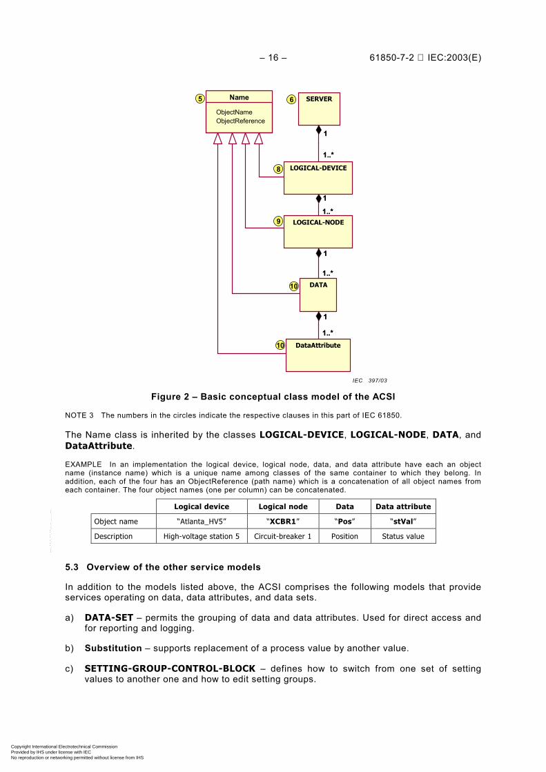
Figure 2 – Basic conceptual class model of the ACSI
NOTE 3 The numbers in the circles indicate the respective clauses in this part of IEC 61850.
The Name class is inherited by the classes LOGICAL-DEVICE, LOGICAL-NODE, DATA, andDataAttribute.
EXAMPLE In an implementation the logical device, logical node, data, and data attribute have each an objectname (instance name) which is a unique name among classes of the same container to which they belong. Inaddition, each of the four has an ObjectReference (path name) which is a concatenation of all object names fromeach container. The four object names (one per column) can be concatenated.
Logical device Logical node Data Data attribute
Object name “Atlanta_HV5” “XCBR1” “Pos” “stVal”
Description High-voltage station 5 Circuit-breaker 1 Position Status value
5.3 Overview of the other service models
In addition to the models listed above, the ACSI comprises the following models that provideservices operating on data, data attributes, and data sets.
a) DATA-SET – permits the grouping of data and data attributes. Used for direct access andfor reporting and logging.
b) Substitution – supports replacement of a process value by another value.
c) SETTING-GROUP-CONTROL-BLOCK – defines how to switch from one set of settingvalues to another one and how to edit setting groups.
IEC 397/03
Copyright International Electrotechnical Commission Provided by IHS under license with IEC
Not for ResaleNo reproduction or networking permitted without license from IHS
--``````-`-`,,`,,`,`,,`---

61850-7-2 © IEC:2003(E) – 17 –
d) REPORT-CONTROL-BLOCK and LOG-CONTROL-BLOCK – describe the conditions forgenerating reports and logs based on parameters set by the client. Reports may betriggered by changes of process data values (for example, state change or dead band) orby quality changes. Logs can be queried for later retrieval. Reports may be sentimmediately or deferred. Reports provide change-of-state and sequence-of-eventsinformation exchange.
e) control blocks for generic substation event (GSE) – supports a fast and reliablesystem-wide distribution of input and output data values; peer-to-peer exchange of IEDbinary status information, for example, a trip signal.
f) control blocks for transmission of sampled values – fast and cyclic transfer ofsamples, for example, of instrument transformers.
g) control – describes the services to control, for example, devices.
h) time and time synchronization – provides the time base for the device and system.
i) file transfer – defines the exchange of large data blocks such as programs.
An overview of the conceptual service model of the ACSI is shown in Figure 3.
1..*
DataAttribute
LOGICAL-DEVICE
SERVERBUFFERED-REPORT-CTRL-BLOCK0..*
LOG0..1
LOG-CONTROL-BLOCK
0..*
1
0..*
0..*
SETTING-GROUP-CONTROL-Block0..1
GOOSE-CONTROL-BLOCK
0..1
GSSE-CONTROL-BLOCK0..1
MULTICAST-SAMPLED-VALUE-CTRL-B.
0..1
0..1
DataSet
1
0..*
1
0..*
1
0..*
1
0..*
1
0..*
1
0..*
1
0..*
1
1
1
1
1
1
11
11
1
1
0..*
1..*1
1
1
1..*
DATA
1
1..*
11
13
14
14
14
14
15
15
16
16
Substitution12
Control17
Time18
File20
6
8
9
10
10
LOGICAL-NODE
0..*
1
0..*
LLN0
UNICAST-SAMPLEDVALUE-CTRL-B.
UNBUFFERED-REPORT-CTRL-BLOCK
Control Blocks
1
Figure 3 – Conceptual service model of the ACSIIEC 398/03
Copyright International Electrotechnical Commission Provided by IHS under license with IEC
Not for ResaleNo reproduction or networking permitted without license from IHS
--``````-`-`,,`,,`,`,,`---

– 18 – 61850-7-2 IEC:2003(E)
NOTE 1 The numbers in the circles indicate the respective clauses in this part of IEC 61850.
NOTE 2 The class diagrams are conceptual. Details are defined in the respective clauses. Comprehensivediagrams are contained in IEC 61850-7-1. The DATA class may be defined recursively. The operations forsubstitution and control are restricted to the lowest level in the DATA class. The DataAttributes may be definedrecursively as well.
The logical node is one of the major building blocks that has associations to most of the otherinformation exchange models, for example, report control, log control, and setting control.Any other information exchange service model, for example, report control, log control, andsetting control shall inherit the ObjectName and ObjectReference as depicted in Figure 2.
NOTE 3 The class models and services are defined using an object-oriented approach allowing for the mapping ofclass models and services to different application layer and middle ware solutions.
Copyright International Electrotechnical Commission Provided by IHS under license with IEC
Not for ResaleNo reproduction or networking permitted without license from IHS
--``````-`-`,,`,,`,`,,`---
61850-7-2 © IEC:2003(E) – 19 –
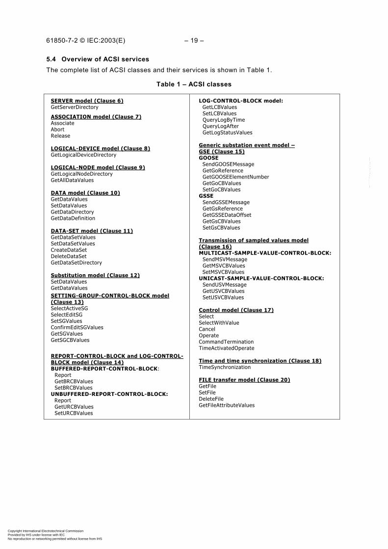
5.4 Overview of ACSI servicesThe complete list of ACSI classes and their services is shown in Table 1.
Table 1 – ACSI classes
SERVER model (Clause 6)GetServerDirectory
ASSOCIATION model (Clause 7)AssociateAbortRelease
LOGICAL-DEVICE model (Clause 8)GetLogicalDeviceDirectory
LOGICAL-NODE model (Clause 9)GetLogicalNodeDirectoryGetAllDataValues
DATA model (Clause 10)GetDataValuesSetDataValuesGetDataDirectoryGetDataDefinition
DATA-SET model (Clause 11)GetDataSetValuesSetDataSetValuesCreateDataSetDeleteDataSetGetDataSetDirectory
Substitution model (Clause 12)SetDataValuesGetDataValuesSETTING-GROUP-CONTROL-BLOCK model(Clause 13)SelectActiveSGSelectEditSGSetSGValuesConfirmEditSGValuesGetSGValuesGetSGCBValues
REPORT-CONTROL-BLOCK and LOG-CONTROL-BLOCK model (Clause 14)BUFFERED-REPORT-CONTROL-BLOCK: Report GetBRCBValues SetBRCBValuesUNBUFFERED-REPORT-CONTROL-BLOCK: Report GetURCBValues SetURCBValues
LOG-CONTROL-BLOCK model: GetLCBValues SetLCBValues QueryLogByTime QueryLogAfter GetLogStatusValues
Generic substation event model –GSE (Clause 15)GOOSE SendGOOSEMessage GetGoReference GetGOOSEElementNumber GetGoCBValues SetGoCBValuesGSSE SendGSSEMessage GetGsReference GetGSSEDataOffset GetGsCBValues SetGsCBValues
Transmission of sampled values model(Clause 16)MULTICAST-SAMPLE-VALUE-CONTROL-BLOCK: SendMSVMessage GetMSVCBValues SetMSVCBValuesUNICAST-SAMPLE-VALUE-CONTROL-BLOCK: SendUSVMessage GetUSVCBValues SetUSVCBValues
Control model (Clause 17)SelectSelectWithValueCancelOperateCommandTerminationTimeActivatedOperate
Time and time synchronization (Clause 18)TimeSynchronization
FILE transfer model (Clause 20)GetFileSetFileDeleteFileGetFileAttributeValues
Copyright International Electrotechnical Commission Provided by IHS under license with IEC
Not for ResaleNo reproduction or networking permitted without license from IHS
--``````-`-`,,`,,`,`,,`---
– 20 – 61850-7-2 IEC:2003(E)
5.5 Type definitions
5.5.1 Data attribute types
IEC 61850-7-2 and IEC 61850-7-3 shall use the types that are defined in the followingsubclauses in order to define the specific data for the application models in IEC 61850-7-4 andthe control blocks in this part of IEC 61850 (for example, report control blocks).
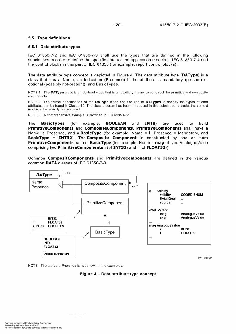
The data attribute type concept is depicted in Figure 4. The data attribute type (DAType) is aclass that has a Name, an indication (Presence) if the attribute is mandatory (present) oroptional (possibly not-present), and BasicTypes.
NOTE 1 The DAType class is an abstract class that is an auxiliary means to construct the primitive and compositecomponents.
NOTE 2 The formal specification of the DAType class and the use of DATypes to specify the types of dataattributes can be found in Clause 10. The class diagram has been introduced in this subclause to depict the contextin which the basic types are used.
NOTE 3 A comprehensive example is provided in IEC 61850-7-1.
The BasicTypes (for example, BOOLEAN and INT8) are used to buildPrimitiveComponents and CompositeComponents. PrimitiveComponents shall have aName, a Presence, and a BasicType (for example, Name = i, Presence = Mandatory, andBasicType = INT32). The Composite Component is constructed by one or morePrimitiveComponents each of BasicType (for example, Name = mag of type AnalogueValuecomprising two PrimitiveComponents i (of INT32) and f (of FLOAT32)).
Common CompositComponents and PrimitiveComponents are defined in the variouscommon DATA classes of IEC 61850-7-3.
DAType
PrimitiveComponent
CompositeComponentNamePresence
1..n
BasicType
1
BOOLEANINT8FLOAT32...VISIBLE-STRING
i INT32f FLOAT32subEna BOOLEAN...
q Qualityvalidity CODED ENUMDetailQual ...source ...
...cVal Vector
mag AnalogueValueang AnalogueValue
...mag AnalogueValue
i INT32f FLOAT32
...
NOTE The attribute Presence is not shown in the examples.
Figure 4 – Data attribute type concept
IEC 399/03
Copyright International Electrotechnical Commission Provided by IHS under license with IEC
Not for ResaleNo reproduction or networking permitted without license from IHS
--``````-`-`,,`,,`,`,,`---
61850-7-2 © IEC:2003(E) – 21 –
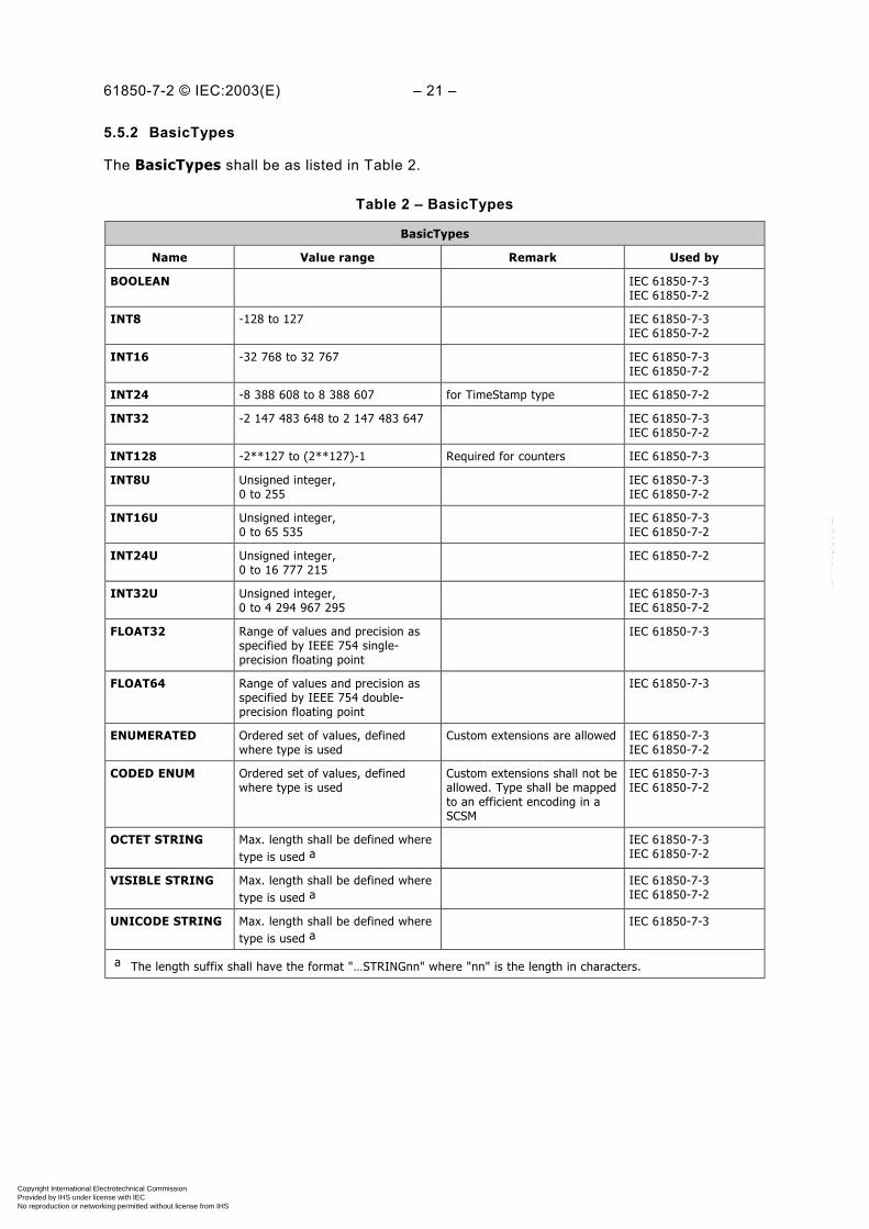
5.5.2 BasicTypes
The BasicTypes shall be as listed in Table 2.
Table 2 – BasicTypes
BasicTypes
Name Value range Remark Used by
BOOLEAN IEC 61850-7-3IEC 61850-7-2
INT8 -128 to 127 IEC 61850-7-3IEC 61850-7-2
INT16 -32 768 to 32 767 IEC 61850-7-3IEC 61850-7-2
INT24 -8 388 608 to 8 388 607 for TimeStamp type IEC 61850-7-2
INT32 -2 147 483 648 to 2 147 483 647 IEC 61850-7-3IEC 61850-7-2
INT128 -2**127 to (2**127)-1 Required for counters IEC 61850-7-3
INT8U Unsigned integer,0 to 255
IEC 61850-7-3IEC 61850-7-2
INT16U Unsigned integer,0 to 65 535
IEC 61850-7-3IEC 61850-7-2
INT24U Unsigned integer,0 to 16 777 215
IEC 61850-7-2
INT32U Unsigned integer,0 to 4 294 967 295
IEC 61850-7-3IEC 61850-7-2
FLOAT32 Range of values and precision asspecified by IEEE 754 single-precision floating point
IEC 61850-7-3
FLOAT64 Range of values and precision asspecified by IEEE 754 double-precision floating point
IEC 61850-7-3
ENUMERATED Ordered set of values, definedwhere type is used
Custom extensions are allowed IEC 61850-7-3IEC 61850-7-2
CODED ENUM Ordered set of values, definedwhere type is used
Custom extensions shall not beallowed. Type shall be mappedto an efficient encoding in aSCSM
IEC 61850-7-3IEC 61850-7-2
OCTET STRING Max. length shall be defined wheretype is used a
IEC 61850-7-3IEC 61850-7-2
VISIBLE STRING Max. length shall be defined wheretype is used a
IEC 61850-7-3IEC 61850-7-2
UNICODE STRING Max. length shall be defined wheretype is used a
IEC 61850-7-3
a The length suffix shall have the format "…STRINGnn" where "nn" is the length in characters.
Copyright International Electrotechnical Commission Provided by IHS under license with IEC
Not for ResaleNo reproduction or networking permitted without license from IHS
--``````-`-`,,`,,`,`,,`---

– 22 – 61850-7-2 IEC:2003(E)
5.5.3 Common ACSI types
5.5.3.1 General
The common ACSI types shall be used for the attribute definitions of the classes (for example,report control blocks) defined in this part of IEC 61850. The common ACSI types may also beused in the application models defined in IEC 61850-7-3 and IEC 61850-7-4.
5.5.3.2 ObjectName
The ObjectName shall specify a unique instance name among instances of a class owned bythe same parent class with a type as specified in Table 3.
Table 3 – ObjectName type
ObjectName type
Attribute name Attribute type Value/value range/explanation Used by
ObjectName VISIBLE STRING32 Name of an instance of a class ofa single hierarchy level
IEC 61850-7-4IEC 61850-7-3IEC 61850-7-2
NOTE Clause 19 specifies constraints on the use of the type ObjectName.
5.5.3.3 ObjectReference
Instances of classes in the hierarchical information model (ACSI class hierarchy of logicaldevice, logical node, data, data attributes) shall be constructed by the concatenation of allinstance names comprising the whole path-name of an instance of a class that identifies theinstance uniquely. The type of the ObjectReference shall be as specified in Table 4.
Table 4 – ObjectReference type
ObjectReference type
Attribute name Attribute type Value/value range/explanation Used by
ObjectReference VISIBLE STRING255 ObjectReference comprises the wholepath-name of an instance of a class thatidentifies the instance uniquely
IEC 61850-7-2
The ObjectReference syntax shall be:
LDName/LNName[.Name[. ...]]
The “/” shall separate the instance name of a logical device (LDName) from the name of aninstance of a logical node (LNName). The “.” shall separate the further names in the hierarchy.The “[ ]” shall indicate an option. The inner square bracket “[. ...]” shall indicate further namesof recursively nested definitions.
NOTE 1 In any case where the context of the text provides sufficient information that an instance of a class ismeant, the term “instance of” is not used.
NOTE 2 Clause 19 specifies constraints on the use of the type ObjectReference.
Copyright International Electrotechnical Commission Provided by IHS under license with IEC
Not for ResaleNo reproduction or networking permitted without license from IHS
--``````-`-`,,`,,`,`,,`---
61850-7-2 © IEC:2003(E) – 23 –
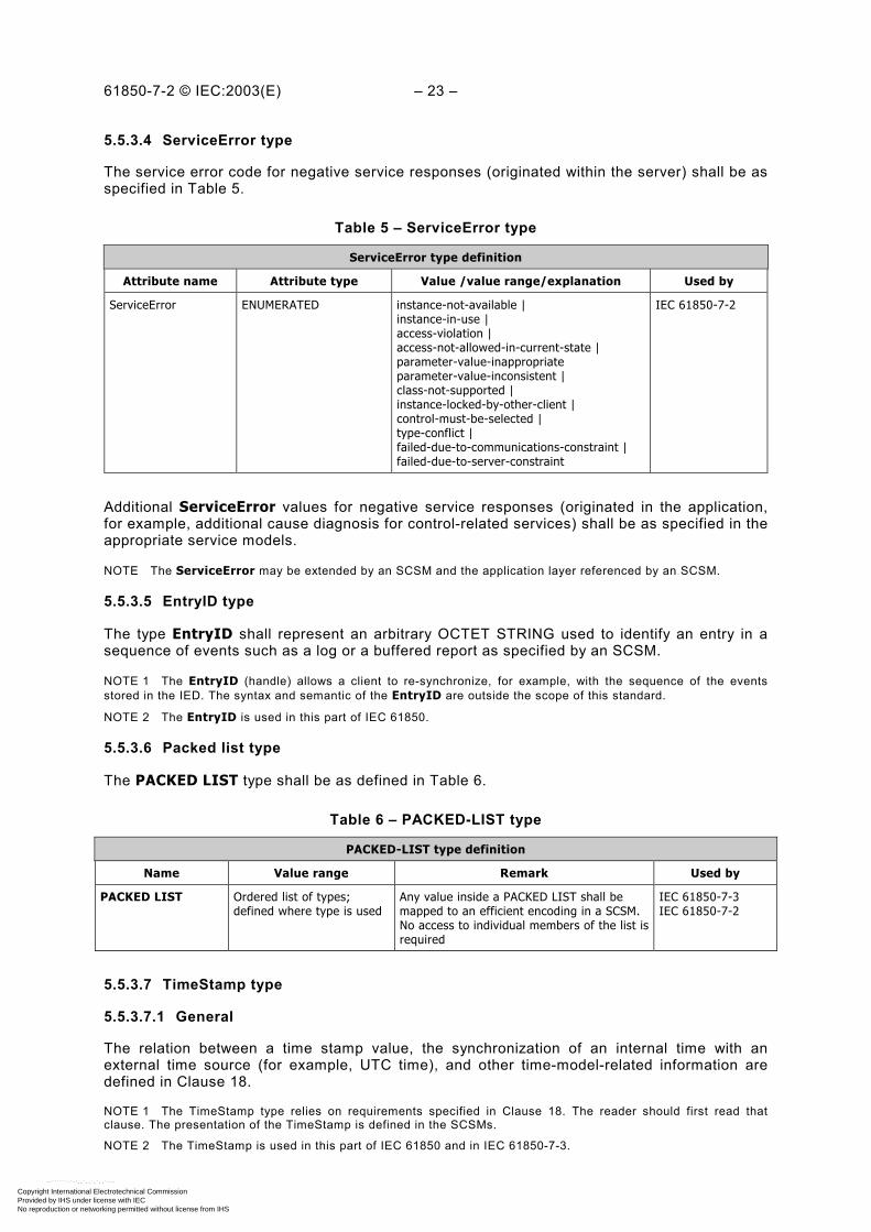
5.5.3.4 ServiceError type
The service error code for negative service responses (originated within the server) shall be asspecified in Table 5.
Table 5 – ServiceError type
ServiceError type definition
Attribute name Attribute type Value /value range/explanation Used by
ServiceError ENUMERATED instance-not-available |instance-in-use |access-violation |access-not-allowed-in-current-state |parameter-value-inappropriateparameter-value-inconsistent |class-not-supported |instance-locked-by-other-client |control-must-be-selected |type-conflict |failed-due-to-communications-constraint |failed-due-to-server-constraint
IEC 61850-7-2
Additional ServiceError values for negative service responses (originated in the application,for example, additional cause diagnosis for control-related services) shall be as specified in theappropriate service models.
NOTE The ServiceError may be extended by an SCSM and the application layer referenced by an SCSM.
5.5.3.5 EntryID type
The type EntryID shall represent an arbitrary OCTET STRING used to identify an entry in asequence of events such as a log or a buffered report as specified by an SCSM.
NOTE 1 The EntryID (handle) allows a client to re-synchronize, for example, with the sequence of the eventsstored in the IED. The syntax and semantic of the EntryID are outside the scope of this standard.
NOTE 2 The EntryID is used in this part of IEC 61850.
5.5.3.6 Packed list type
The PACKED LIST type shall be as defined in Table 6.
Table 6 – PACKED-LIST type
PACKED-LIST type definition
Name Value range Remark Used by
PACKED LIST Ordered list of types;defined where type is used
Any value inside a PACKED LIST shall bemapped to an efficient encoding in a SCSM.No access to individual members of the list isrequired
IEC 61850-7-3IEC 61850-7-2
5.5.3.7 TimeStamp type
5.5.3.7.1 General
The relation between a time stamp value, the synchronization of an internal time with anexternal time source (for example, UTC time), and other time-model-related information aredefined in Clause 18.
NOTE 1 The TimeStamp type relies on requirements specified in Clause 18. The reader should first read thatclause. The presentation of the TimeStamp is defined in the SCSMs.
NOTE 2 The TimeStamp is used in this part of IEC 61850 and in IEC 61850-7-3.
Copyright International Electrotechnical Commission Provided by IHS under license with IEC
Not for ResaleNo reproduction or networking permitted without license from IHS
--``````-`-`,,`,,`,`,,`---
– 24 – 61850-7-2 IEC:2003(E)
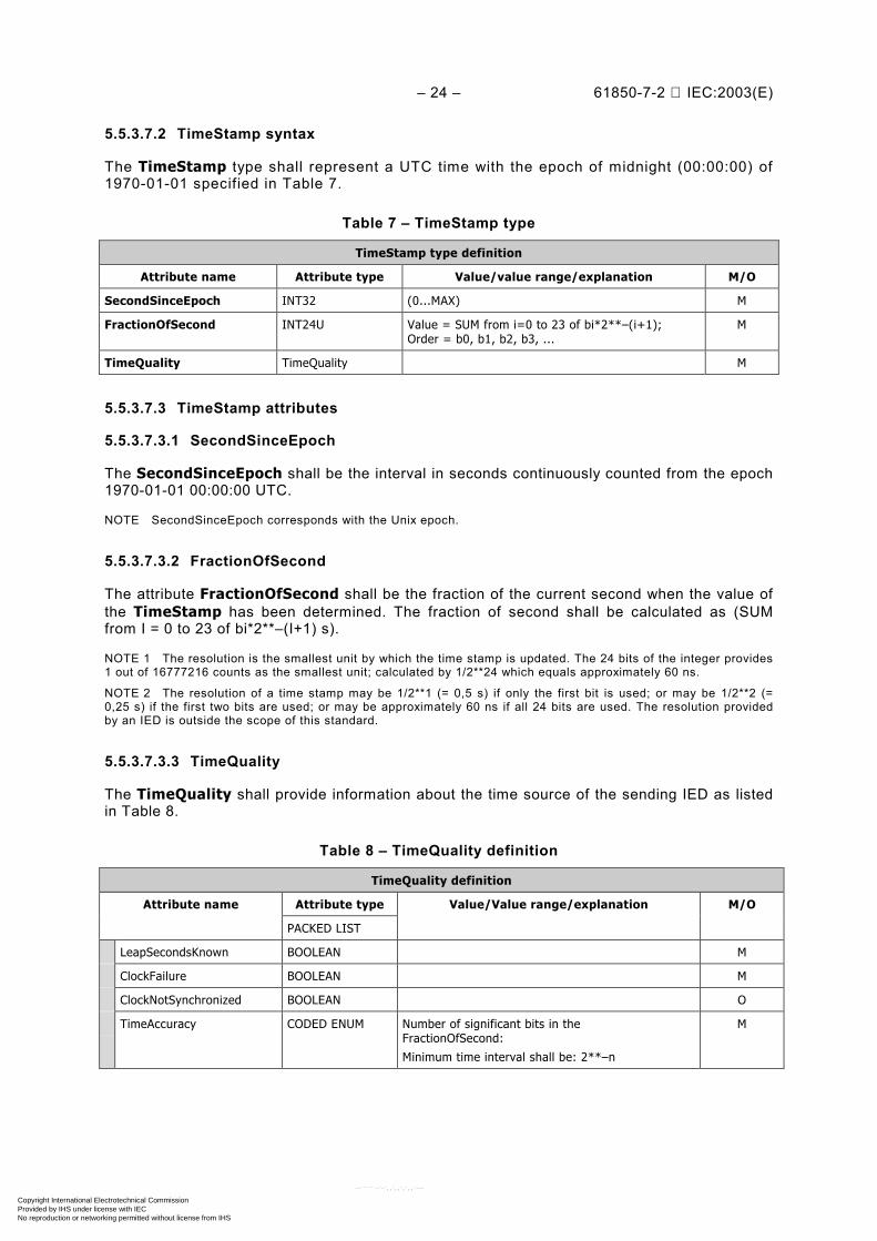
5.5.3.7.2 TimeStamp syntax
The TimeStamp type shall represent a UTC time with the epoch of midnight (00:00:00) of1970-01-01 specified in Table 7.
Table 7 – TimeStamp type
TimeStamp type definition
Attribute name Attribute type Value/value range/explanation M/O
SecondSinceEpoch INT32 (0...MAX) M
FractionOfSecond INT24U Value = SUM from i=0 to 23 of bi*2**–(i+1);Order = b0, b1, b2, b3, ...
M
TimeQuality TimeQuality M
5.5.3.7.3 TimeStamp attributes
5.5.3.7.3.1 SecondSinceEpoch
The SecondSinceEpoch shall be the interval in seconds continuously counted from the epoch1970-01-01 00:00:00 UTC.
NOTE SecondSinceEpoch corresponds with the Unix epoch.
5.5.3.7.3.2 FractionOfSecond
The attribute FractionOfSecond shall be the fraction of the current second when the value ofthe TimeStamp has been determined. The fraction of second shall be calculated as (SUMfrom I = 0 to 23 of bi*2**–(I+1) s).
NOTE 1 The resolution is the smallest unit by which the time stamp is updated. The 24 bits of the integer provides1 out of 16777216 counts as the smallest unit; calculated by 1/2**24 which equals approximately 60 ns.
NOTE 2 The resolution of a time stamp may be 1/2**1 (= 0,5 s) if only the first bit is used; or may be 1/2**2 (=0,25 s) if the first two bits are used; or may be approximately 60 ns if all 24 bits are used. The resolution providedby an IED is outside the scope of this standard.
5.5.3.7.3.3 TimeQuality
The TimeQuality shall provide information about the time source of the sending IED as listedin Table 8.
Table 8 – TimeQuality definition
TimeQuality definition
Attribute name Attribute type Value/Value range/explanation M/O
PACKED LIST
LeapSecondsKnown BOOLEAN M
ClockFailure BOOLEAN M
ClockNotSynchronized BOOLEAN O
TimeAccuracy CODED ENUM Number of significant bits in theFractionOfSecond:
Minimum time interval shall be: 2**–n
M
Copyright International Electrotechnical Commission Provided by IHS under license with IEC
Not for ResaleNo reproduction or networking permitted without license from IHS
--``````-`-`,,`,,`,`,,`---
61850-7-2 © IEC:2003(E) – 25 –
LeapSecondsKnown: The value TRUE of the attribute LeapSecondsKnown shall indicatethat the value for SecondSinceEpoch takes into account all leap seconds occurred. If it isFALSE then the value does not take into account the leap seconds that occurred before theinitialization of the time source of the device.
ClockFailure: The attribute clockFailure shall indicate that the time source of the sendingdevice is unreliable. The value of the TimeStamp shall be ignored.
ClockNotSynchronized: The attribute clockNotSynchronized shall indicate that the timesource of the sending device is not synchronized with the external UTC time.
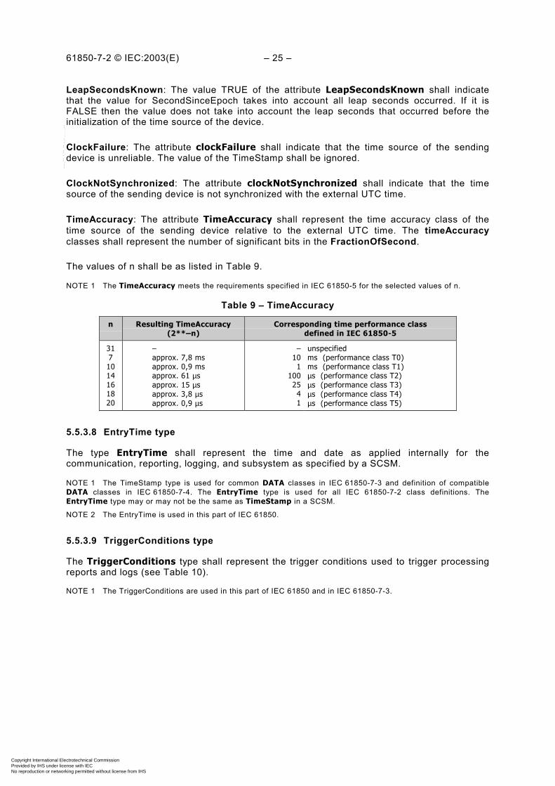
TimeAccuracy: The attribute TimeAccuracy shall represent the time accuracy class of thetime source of the sending device relative to the external UTC time. The timeAccuracyclasses shall represent the number of significant bits in the FractionOfSecond.
The values of n shall be as listed in Table 9.
NOTE 1 The TimeAccuracy meets the requirements specified in IEC 61850-5 for the selected values of n.
Table 9 – TimeAccuracy
n Resulting TimeAccuracy(2**–n)
Corresponding time performance classdefined in IEC 61850-5
3171014161820
–approx. 7,8 msapprox. 0,9 msapprox. 61 µsapprox. 15 µsapprox. 3,8 µsapprox. 0,9 µs
–101
100 25 4 1
unspecifiedms (performance class T0)ms (performance class T1)µs (performance class T2)µs (performance class T3)µs (performance class T4)µs (performance class T5)
5.5.3.8 EntryTime type
The type EntryTime shall represent the time and date as applied internally for thecommunication, reporting, logging, and subsystem as specified by a SCSM.
NOTE 1 The TimeStamp type is used for common DATA classes in IEC 61850-7-3 and definition of compatibleDATA classes in IEC 61850-7-4. The EntryTime type is used for all IEC 61850-7-2 class definitions. TheEntryTime type may or may not be the same as TimeStamp in a SCSM.
NOTE 2 The EntryTime is used in this part of IEC 61850.
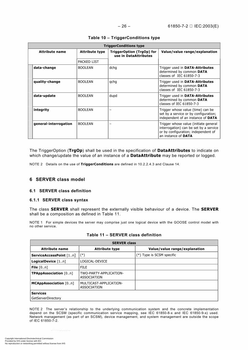
5.5.3.9 TriggerConditions type
The TriggerConditions type shall represent the trigger conditions used to trigger processingreports and logs (see Table 10).
NOTE 1 The TriggerConditions are used in this part of IEC 61850 and in IEC 61850-7-3.
Copyright International Electrotechnical Commission Provided by IHS under license with IEC
Not for ResaleNo reproduction or networking permitted without license from IHS
--``````-`-`,,`,,`,`,,`---
– 26 – 61850-7-2 IEC:2003(E)
Table 10 – TriggerConditions type
TriggerConditions type
Attribute name Attribute type TriggerOption (TrgOp) foruse in DataAttributes
Value/value range/explanation
PACKED LIST
data-change BOOLEAN dchg Trigger used in DATA-Attributesdetermined by common DATAclasses of IEC 61850-7-3
quality-change BOOLEAN qchg Trigger used in DATA-Attributesdetermined by common DATAclasses of IEC 61850-7-3
data-update BOOLEAN dupd Trigger used in DATA-Attributesdetermined by common DATAclasses of IEC 61850-7-3
integrity BOOLEAN – Trigger whose value (time) can beset by a service or by configuration;independent of an instance of DATA
general-interrogation BOOLEAN – Trigger whose value (initiate generalinterrogation) can be set by a serviceor by configuration; independent ofan instance of DATA
The TriggerOption (TrgOp) shall be used in the specification of DataAttributes to indicate onwhich change/update the value of an instance of a DataAttribute may be reported or logged.
NOTE 2 Details on the use of TriggerConditions are defined in 10.2.2.4.3 and Clause 14.
6 SERVER class model
6.1 SERVER class definition
6.1.1 SERVER class syntax
The class SERVER shall represent the externally visible behaviour of a device. The SERVERshall be a composition as defined in Table 11.
NOTE 1 For simple devices the server may comprise just one logical device with the GOOSE control model withno other service.
Table 11 – SERVER class definition
SERVER class
Attribute name Attribute type Value/value range/explanation
ServiceAccessPoint [1..n] (*) (*) Type is SCSM specific
LogicalDevice [1..n] LOGICAL-DEVICE
File [0..n] FILE
TPAppAssociation [0..n] TWO-PARTY-APPLICATION-ASSOCIATION
MCAppAssociation [0..n] MULTICAST-APPLICATION-ASSOCIATION
ServicesGetServerDirectory
NOTE 2 The server’s relationship to the underlying communication system and the concrete implementationdepend on the SCSM (specific communication service mapping, see IEC 61850-8-x and IEC 61850-9-x) used.Network management (as part of an SCSM), device management, and system management are outside the scopeof IEC 61850-7-2.
Copyright International Electrotechnical Commission Provided by IHS under license with IEC
Not for ResaleNo reproduction or networking permitted without license from IHS
--``````-`-`,,`,,`,`,,`---

61850-7-2 © IEC:2003(E) – 27 –
6.1.2 SERVER class attributes
6.1.2.1 ServiceAccessPoint
The attribute ServiceAccessPoint shall identify a SERVER within the scope of a system.
NOTE The ServiceAccessPoint is an abstraction of an address used to identify the server in the underlyingSCSM. The type depends on the SCSM and should be defined there. A specific ServiceAccessPoint is required bymost services to address a server. Nevertheless, it has not been included explicitly in the service parameter tablesthroughout this part of IEC 61850.
6.1.2.2 LogicalDevice [1..n]
The attribute LogicalDevice shall identify a LogicalDevice that is contained in a SERVER.
6.1.2.3 File [0..n]
The attribute File shall identify a File contained in a SERVER.
6.1.2.4 TPAppAssociation [0..n] – two-party application association
The attribute TPAppAssociation shall identify a client with which a SERVER maintains a two-party application association.
NOTE Details can be found in Clause 7.
6.1.2.5 MCAppAssociation [0..n] – multicast application association
The attribute MCAppAssociation shall identify a subscriber with which a SERVER (publisher)maintains a multicast application association.
NOTE Details can be found in Clause 7.
6.2 Server class services
6.2.1 Overview of directory and GetDefinition services
To support self-description of a device several GetXXDirectory and GetXXDefinition servicesas shown in Figure 5 are specified in this part of IEC 61850.
LD
LNLN LN
GetLDDirectory (LDName)response (LNNames)
DataData
GetLNDirectory (LNName)response (DataNames)
GetDataDirectory (DataName)resp. (DAttrNames)
response
GetDataDefinition (DataName)or (DName.Attr)
Server
LD
GetServerDirectory (LD or File)response (LDNames or
FileNames)
(all DAttr Definitions)or (one DAttr Definition)
Figure 5 – Overview about GetDirectory and GetDefinition servicesIEC 400/03
Copyright International Electrotechnical Commission Provided by IHS under license with IEC
Not for ResaleNo reproduction or networking permitted without license from IHS
--``````-`-`,,`,,`,`,,`---
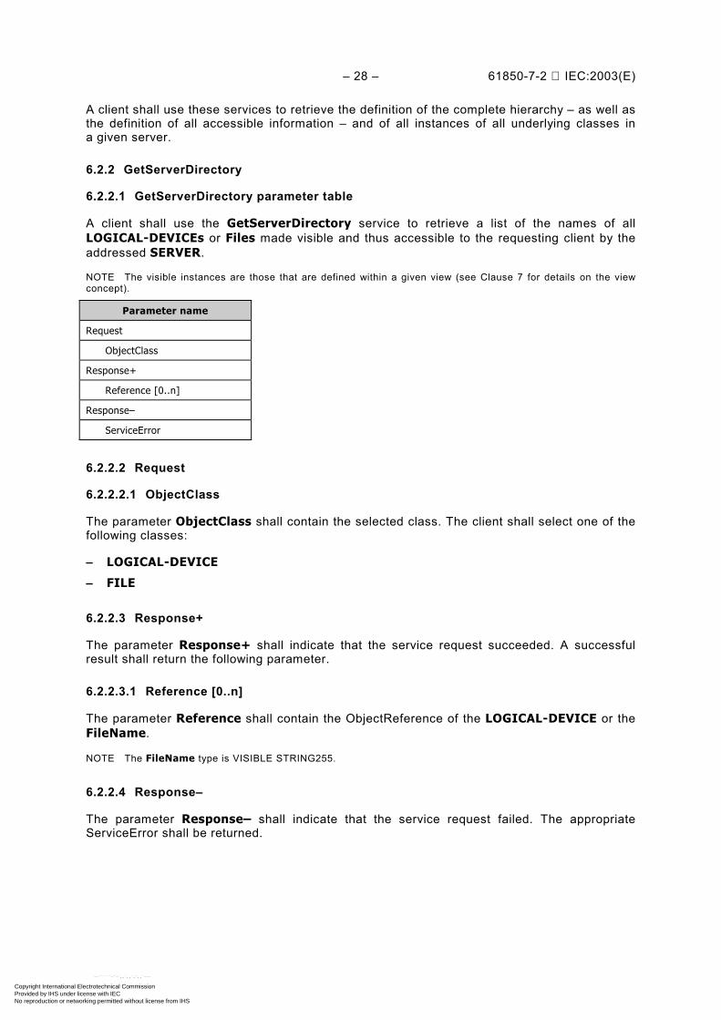
– 28 – 61850-7-2 IEC:2003(E)
A client shall use these services to retrieve the definition of the complete hierarchy – as well asthe definition of all accessible information – and of all instances of all underlying classes ina given server.
6.2.2 GetServerDirectory
6.2.2.1 GetServerDirectory parameter table
A client shall use the GetServerDirectory service to retrieve a list of the names of allLOGICAL-DEVICEs or Files made visible and thus accessible to the requesting client by theaddressed SERVER.
NOTE The visible instances are those that are defined within a given view (see Clause 7 for details on the viewconcept).
Parameter name
Request
ObjectClass
Response+
Reference [0..n]
Response–
ServiceError
6.2.2.2 Request
6.2.2.2.1 ObjectClass
The parameter ObjectClass shall contain the selected class. The client shall select one of thefollowing classes:
– LOGICAL-DEVICE
– FILE
6.2.2.3 Response+
The parameter Response+ shall indicate that the service request succeeded. A successfulresult shall return the following parameter.
6.2.2.3.1 Reference [0..n]
The parameter Reference shall contain the ObjectReference of the LOGICAL-DEVICE or theFileName.
NOTE The FileName type is VISIBLE STRING255.
6.2.2.4 Response–
The parameter Response– shall indicate that the service request failed. The appropriateServiceError shall be returned.
Copyright International Electrotechnical Commission Provided by IHS under license with IEC
Not for ResaleNo reproduction or networking permitted without license from IHS
--``````-`-`,,`,,`,`,,`---
61850-7-2 © IEC:2003(E) – 29 –
7 Application association model
7.1 Introduction
The application association model consists of provisions on how the communication betweenthe various types of devices is achieved. The model comprises
– class definitions of associations (two-party and multicast); and– access control concepts (how to restrict access to instances in a server).
The security requirements for the restriction of access to the data in a server is definedin IEC 61850-5.
NOTE Security requirements are implemented by the SCSMs.
7.2 Concept of application associations
The application association model defines
– the services provided for managing associations between client and server (two-partyapplication association); and
– the services provided for managing associations for multicast messaging (for example,GOOSE and transmission of sampled values).
The two-party application association class shall convey service requests and responses(thus transferring unconfirmed and confirmed services). The multicast applicationassociation class shall be capable of conveying unconfirmed services (in one direction only).
Application associations provide a mechanism for controlling the access to the instances ofa device (access control).
NOTE The details of an application association model are defined in the SCSMs. The following descriptionsprovide a conceptual model of the application associations between devices.
7.3 Access control
The access control model provides the capability to restrict the access of a specific client toclass instances, class instance attributes, and ACSI services acting upon class instances of aspecific server. The ACSI server contains a set of, for example, LOGICAL-DEVICEs,LOGICAL-NODEs, DATA, or report controls. The set of instances visible (and thereforeaccessible) to a client is restricted on the basis of the identification of the client and the accesscontrol specification of the server. This restricted set is called a virtual access view. A virtualaccess view may not only restrict the visibility of instances or attributes but also the supportedservice. The concept of a virtual access view is illustrated in Figure 6.
NOTE 1 The virtual access view is the authentication’s view of the IED’s data model.
Copyright International Electrotechnical Commission Provided by IHS under license with IEC
Not for ResaleNo reproduction or networking permitted without license from IHS
--``````-`-`,,`,,`,`,,`---
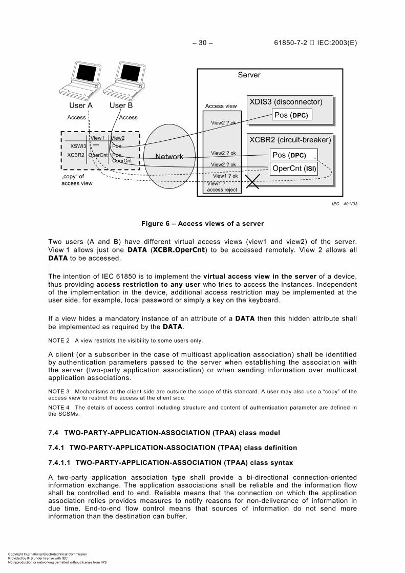
– 30 – 61850-7-2 IEC:2003(E)
View1 View2Pos
XCBR2
XSWI3
OperCntPosOperCnt
XDIS3 (disconnector)XDIS3 (disconnector)
Pos (DPC)
XCBR2 (circuit-breaker)XCBR2 (circuit-breaker)
Pos (DPC)
OperCnt (ISI)
Server
Network
User BUser A
View1 ? ok
View2 ? ok
View2 ? ok
View2 ? ok
Access view
AccessAccess
View1 ? access reject
„copy“ ofaccess view
Figure 6 – Access views of a server
Two users (A and B) have different virtual access views (view1 and view2) of the server.View 1 allows just one DATA (XCBR.OperCnt) to be accessed remotely. View 2 allows allDATA to be accessed.
The intention of IEC 61850 is to implement the virtual access view in the server of a device,thus providing access restriction to any user who tries to access the instances. Independentof the implementation in the device, additional access restriction may be implemented at theuser side, for example, local password or simply a key on the keyboard.
If a view hides a mandatory instance of an attribute of a DATA then this hidden attribute shallbe implemented as required by the DATA.
NOTE 2 A view restricts the visibility to some users only.
A client (or a subscriber in the case of multicast application association) shall be identifiedby authentication parameters passed to the server when establishing the association withthe server (two-party application association) or when sending information over multicastapplication associations.
NOTE 3 Mechanisms at the client side are outside the scope of this standard. A user may also use a “copy” of theaccess view to restrict the access at the client side.
NOTE 4 The details of access control including structure and content of authentication parameter are defined inthe SCSMs.
7.4 TWO-PARTY-APPLICATION-ASSOCIATION (TPAA) class model
7.4.1 TWO-PARTY-APPLICATION-ASSOCIATION (TPAA) class definition
7.4.1.1 TWO-PARTY-APPLICATION-ASSOCIATION (TPAA) class syntax
A two-party application association type shall provide a bi-directional connection-orientedinformation exchange. The application associations shall be reliable and the information flowshall be controlled end to end. Reliable means that the connection on which the applicationassociation relies provides measures to notify reasons for non-deliverance of information indue time. End-to-end flow control means that sources of information do not send moreinformation than the destination can buffer.
IEC 401/03
Copyright International Electrotechnical Commission Provided by IHS under license with IEC
Not for ResaleNo reproduction or networking permitted without license from IHS
--``````-`-`,,`,,`,`,,`---
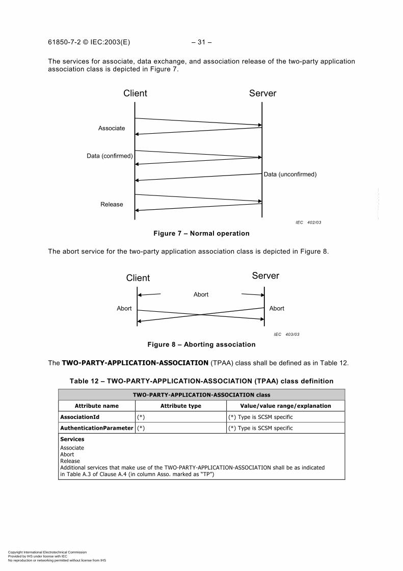
61850-7-2 © IEC:2003(E) – 31 –
The services for associate, data exchange, and association release of the two-party applicationassociation class is depicted in Figure 7.
Associate
ServerClient
Data (confirmed)
Data (unconfirmed)
Release
Figure 7 – Normal operation
The abort service for the two-party application association class is depicted in Figure 8.
ServerClientAbort
Abort Abort
Figure 8 – Aborting association
The TWO-PARTY-APPLICATION-ASSOCIATION (TPAA) class shall be defined as in Table 12.
Table 12 – TWO-PARTY-APPLICATION-ASSOCIATION (TPAA) class definition
TWO-PARTY-APPLICATION-ASSOCIATION class
Attribute name Attribute type Value/value range/explanation
AssociationId (*) (*) Type is SCSM specific
AuthenticationParameter (*) (*) Type is SCSM specific
ServicesAssociateAbortReleaseAdditional services that make use of the TWO-PARTY-APPLICATION-ASSOCIATION shall be as indicatedin Table A.3 of Clause A.4 (in column Asso. marked as “TP”)
IEC 402/03
IEC 403/03
Copyright International Electrotechnical Commission Provided by IHS under license with IEC
Not for ResaleNo reproduction or networking permitted without license from IHS
--``````-`-`,,`,,`,`,,`---

– 32 – 61850-7-2 IEC:2003(E)
7.4.1.2 TWO-PARTY-APPLICATION-ASSOCIATION (TPAA) class attributes
7.4.1.2.1 AssociationId
The attribute AssociationId shall specify the identification used to identify the applicationassociations.
NOTE The type of the AssociationId is defined in the SCSMs and it may be exchanged in an SCSM or be usedlocally only.
7.4.1.2.2 AuthenticationParameter
The attribute authenticationParameter shall represent the information required to grantpermission to access instances of a specific access view to a server.
NOTE A minimum set of parameters is user identification, view and password. The details are defined inthe SCSMs.
7.4.2 Two-party application association services
7.4.2.1 Overview
For TWO-PARTY-APPLICATION-ASSOCIATION the following services are defined.
Service Description
Associate Establish an association
Abort Abort an association
Release Release an association
7.4.2.2 Associate
7.4.2.2.1 Associate parameter
A client shall use the Associate service to establish an application association of type two-party with a specific server.
Parameter name
Request
ServerAccessPointReference
AuthenticationParameter
Response+
AssociationId
Result
Response–
ServiceError
7.4.2.2.2 Request
7.4.2.2.2.1 ServerAccessPointReference
The parameter ServeAccessPointReference shall identify the server, with which theapplication association shall be established.
Copyright International Electrotechnical Commission Provided by IHS under license with IEC
Not for ResaleNo reproduction or networking permitted without license from IHS
--``````-`-`,,`,,`,`,,`---
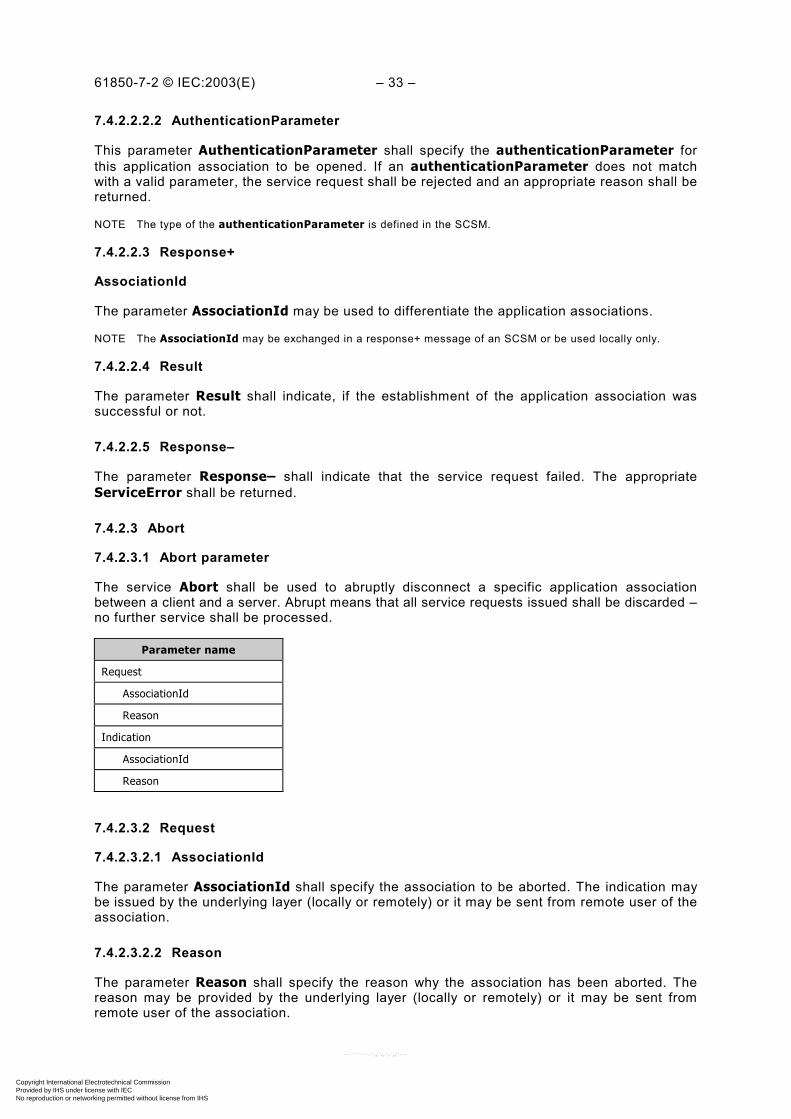
61850-7-2 © IEC:2003(E) – 33 –
7.4.2.2.2.2 AuthenticationParameter
This parameter AuthenticationParameter shall specify the authenticationParameter forthis application association to be opened. If an authenticationParameter does not matchwith a valid parameter, the service request shall be rejected and an appropriate reason shall bereturned.
NOTE The type of the authenticationParameter is defined in the SCSM.
7.4.2.2.3 Response+
AssociationId
The parameter AssociationId may be used to differentiate the application associations.
NOTE The AssociationId may be exchanged in a response+ message of an SCSM or be used locally only.
7.4.2.2.4 Result
The parameter Result shall indicate, if the establishment of the application association wassuccessful or not.
7.4.2.2.5 Response–
The parameter Response– shall indicate that the service request failed. The appropriateServiceError shall be returned.
7.4.2.3 Abort
7.4.2.3.1 Abort parameter
The service Abort shall be used to abruptly disconnect a specific application associationbetween a client and a server. Abrupt means that all service requests issued shall be discarded –no further service shall be processed.
Parameter name
Request
AssociationId
Reason
Indication
AssociationId
Reason
7.4.2.3.2 Request
7.4.2.3.2.1 AssociationId
The parameter AssociationId shall specify the association to be aborted. The indication maybe issued by the underlying layer (locally or remotely) or it may be sent from remote user of theassociation.
7.4.2.3.2.2 Reason
The parameter Reason shall specify the reason why the association has been aborted. Thereason may be provided by the underlying layer (locally or remotely) or it may be sent fromremote user of the association.
Copyright International Electrotechnical Commission Provided by IHS under license with IEC
Not for ResaleNo reproduction or networking permitted without license from IHS
--``````-`-`,,`,,`,`,,`---
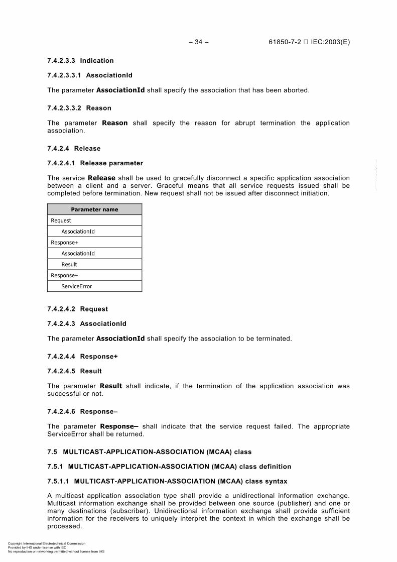
– 34 – 61850-7-2 IEC:2003(E)
7.4.2.3.3 Indication
7.4.2.3.3.1 AssociationId
The parameter AssociationId shall specify the association that has been aborted.
7.4.2.3.3.2 Reason
The parameter Reason shall specify the reason for abrupt termination the applicationassociation.
7.4.2.4 Release
7.4.2.4.1 Release parameter
The service Release shall be used to gracefully disconnect a specific application associationbetween a client and a server. Graceful means that all service requests issued shall becompleted before termination. New request shall not be issued after disconnect initiation.
Parameter name
Request
AssociationId
Response+
AssociationId
Result
Response–
ServiceError
7.4.2.4.2 Request
7.4.2.4.3 AssociationId
The parameter AssociationId shall specify the association to be terminated.
7.4.2.4.4 Response+
7.4.2.4.5 Result
The parameter Result shall indicate, if the termination of the application association wassuccessful or not.
7.4.2.4.6 Response–
The parameter Response– shall indicate that the service request failed. The appropriateServiceError shall be returned.
7.5 MULTICAST-APPLICATION-ASSOCIATION (MCAA) class
7.5.1 MULTICAST-APPLICATION-ASSOCIATION (MCAA) class definition
7.5.1.1 MULTICAST-APPLICATION-ASSOCIATION (MCAA) class syntax
A multicast application association type shall provide a unidirectional information exchange.Multicast information exchange shall be provided between one source (publisher) and one ormany destinations (subscriber). Unidirectional information exchange shall provide sufficientinformation for the receivers to uniquely interpret the context in which the exchange shall beprocessed.
Copyright International Electrotechnical Commission Provided by IHS under license with IEC
Not for ResaleNo reproduction or networking permitted without license from IHS
--``````-`-`,,`,,`,`,,`---
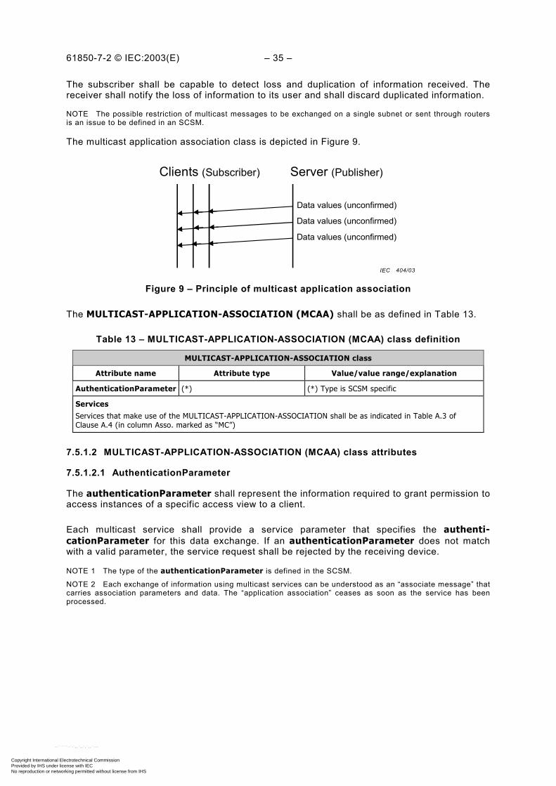
61850-7-2 © IEC:2003(E) – 35 –
The subscriber shall be capable to detect loss and duplication of information received. Thereceiver shall notify the loss of information to its user and shall discard duplicated information.
NOTE The possible restriction of multicast messages to be exchanged on a single subnet or sent through routersis an issue to be defined in an SCSM.
The multicast application association class is depicted in Figure 9.
Server (Publisher)Clients (Subscriber)
Data values (unconfirmed)
Data values (unconfirmed)
Data values (unconfirmed)
Figure 9 – Principle of multicast application association
The MULTICAST-APPLICATION-ASSOCIATION (MCAA) shall be as defined in Table 13.
Table 13 – MULTICAST-APPLICATION-ASSOCIATION (MCAA) class definition
MULTICAST-APPLICATION-ASSOCIATION class
Attribute name Attribute type Value/value range/explanation
AuthenticationParameter (*) (*) Type is SCSM specific
ServicesServices that make use of the MULTICAST-APPLICATION-ASSOCIATION shall be as indicated in Table A.3 ofClause A.4 (in column Asso. marked as “MC”)
7.5.1.2 MULTICAST-APPLICATION-ASSOCIATION (MCAA) class attributes
7.5.1.2.1 AuthenticationParameter
The authenticationParameter shall represent the information required to grant permission toaccess instances of a specific access view to a client.
Each multicast service shall provide a service parameter that specifies the authenti-cationParameter for this data exchange. If an authenticationParameter does not matchwith a valid parameter, the service request shall be rejected by the receiving device.
NOTE 1 The type of the authenticationParameter is defined in the SCSM.
NOTE 2 Each exchange of information using multicast services can be understood as an “associate message” thatcarries association parameters and data. The “application association” ceases as soon as the service has beenprocessed.
IEC 404/03
Copyright International Electrotechnical Commission Provided by IHS under license with IEC
Not for ResaleNo reproduction or networking permitted without license from IHS
--``````-`-`,,`,,`,`,,`---
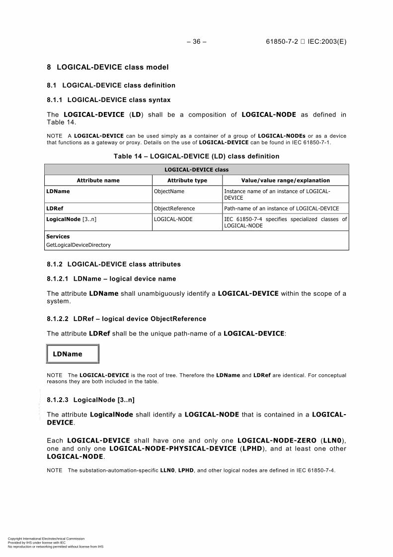
– 36 – 61850-7-2 IEC:2003(E)
8 LOGICAL-DEVICE class model
8.1 LOGICAL-DEVICE class definition
8.1.1 LOGICAL-DEVICE class syntax
The LOGICAL-DEVICE (LD) shall be a composition of LOGICAL-NODE as defined inTable 14.
NOTE A LOGICAL-DEVICE can be used simply as a container of a group of LOGICAL-NODEs or as a devicethat functions as a gateway or proxy. Details on the use of LOGICAL-DEVICE can be found in IEC 61850-7-1.
Table 14 – LOGICAL-DEVICE (LD) class definition
LOGICAL-DEVICE class
Attribute name Attribute type Value/value range/explanation
LDName ObjectName Instance name of an instance of LOGICAL-DEVICE
LDRef ObjectReference Path-name of an instance of LOGICAL-DEVICE
LogicalNode [3..n] LOGICAL-NODE IEC 61850-7-4 specifies specialized classes ofLOGICAL-NODE
ServicesGetLogicalDeviceDirectory
8.1.2 LOGICAL-DEVICE class attributes
8.1.2.1 LDName – logical device name
The attribute LDName shall unambiguously identify a LOGICAL-DEVICE within the scope of asystem.
8.1.2.2 LDRef – logical device ObjectReference
The attribute LDRef shall be the unique path-name of a LOGICAL-DEVICE:
LDName
NOTE The LOGICAL-DEVICE is the root of tree. Therefore the LDName and LDRef are identical. For conceptualreasons they are both included in the table.
8.1.2.3 LogicalNode [3..n]
The attribute LogicalNode shall identify a LOGICAL-NODE that is contained in a LOGICAL-DEVICE.
Each LOGICAL-DEVICE shall have one and only one LOGICAL-NODE-ZERO (LLN0),one and only one LOGICAL-NODE-PHYSICAL-DEVICE (LPHD), and at least one otherLOGICAL-NODE.
NOTE The substation-automation-specific LLN0, LPHD, and other logical nodes are defined in IEC 61850-7-4.
Copyright International Electrotechnical Commission Provided by IHS under license with IEC
Not for ResaleNo reproduction or networking permitted without license from IHS
--``````-`-`,,`,,`,`,,`---
61850-7-2 © IEC:2003(E) – 37 –
8.2 LOGICAL-DEVICE class services
8.2.1 GetLogicalDeviceDirectory
8.2.1.1 GetLogicalDeviceDirectory parameter table
A client shall use the GetLogicalDeviceDirectory service to retrieve the list of theObjectReferences of all LOGICAL-NODEs made visible and thus accessible to the request-ing client by the referenced LOGICAL-DEVICE.
NOTE The visible instances are those that are defined within a given view (see Clause 7 for details onthe view concept).
Parameter Name
Request
LDReference
Response+
LNReference [3..n]
Response–
ServiceError
8.2.1.2 Request
8.2.1.2.1 LDReference – logical device ObjectReference
The parameter LDReference shall contain the ObjectReference LDRef of a LOGICAL-DEVICE.
8.2.1.3 Response+
The parameter Response+ shall indicate that the service request succeeded. A successfulresult shall return the following parameter.
8.2.1.3.1 LNReference [3..n] – logical node ObjectReference
The parameter LNReference shall contain the ObjectReference LNRef of a LOGICAL-NODEfrom the referenced LOGICAL-DEVICE.
8.2.1.4 Response–
The parameter Response– shall indicate that the service request failed. The appropriateServiceError shall be returned.
Copyright International Electrotechnical Commission Provided by IHS under license with IEC
Not for ResaleNo reproduction or networking permitted without license from IHS
--``````-`-`,,`,,`,`,,`---

– 38 – 61850-7-2 IEC:2003(E)
9 LOGICAL-NODE class model
9.1 LOGICAL-NODE class definition
9.1.1 LOGICAL-NODE class syntax
The LOGICAL-NODE shall be a composition of DATA, DATA-SET, BRCB, URCB, LCB, LOG,SGCB, GoCB, GsCB, MSVCB, and USVCB as defined in Table 15.
Table 15 – LOGICAL-NODE (LN) class definition
LOGICAL-NODE class
Attribute name Attribute type Explanation
LNName ObjectName Instance name of an instance ofLOGICAL-NODE
LNRef ObjectReference Path-name of an instance of LOGICAL-NODE
Data [1..n] DATA
DataSet [0..n] DATA-SET
BufferedReportControlBlock [0..n] BRCB
UnbufferedReportControlBlock [0..n] URCB
LogControlBlock [0..n] LCB
IF compatible LN class defined in IEC 61850-7-4 equals LLN0
SettingGroupControlBlock [0..1] SGCB
Log [0..1] LOG
GOOSEControlBlock [0..n] GoCB
GSSEControlBlock [0..n] GsCB
MulticastSampledValueControlBlock [0..n] MSVCB
UnicastSampledValueControlBlock [0..n] USVCB
ServicesGetLogicalNodeDirectoryGetAllDataValues
NOTE 1 IEC 61850-7-4 defines specialized logical node classes – the compatible logical node classes, forexample, XCBR representing circuit-breakers.
The definition of LOGICAL-NODEs for the substation-application domain is refined bythe definition of specific DATA in IEC 61850-7-4. The definitions in IEC 61850-7-4 (andIEC 61850-7-3 for the common DATA classes) shall be taken into account to get the com-prehensive definition of substation-domain-specific LOGICAL-NODEs.
NOTE 2 IEC 61850-7-4 defines further attributes for LOGICAL-NODEs; for example,, the mode (behaviour: ON,BLOCKED, TEST, etc.) of the substation-specific LOGICAL-NODE is defined in IEC 61850-7-4. The state model ofa LOGICAL-NODE is modelled as a specific DATA (named Mod).
9.1.2 LOGICAL-NODE class attributes
9.1.2.1 LNName – Logical node name
The attribute LNName shall unambiguously identify LOGICAL-NODE within the scope ofLOGICAL-DEVICE.
Copyright International Electrotechnical Commission Provided by IHS under license with IEC
Not for ResaleNo reproduction or networking permitted without license from IHS
--``````-`-`,,`,,`,`,,`---
61850-7-2 © IEC:2003(E) – 39 –
9.1.2.2 LNRef – Logical node ObjectReference
The attribute LNRef shall be the unique path-name of a LOGICAL-NODE.
The ObjectReference LNRef shall be:
LDName/LNName
9.1.2.3 Data [1..n]
The attribute Data shall identify DATA (see Clause 10) that is contained in the LOGICAL-NODE.
NOTE IEC 61850-7-4 defines standardized DATA called compatible DATA classes.
9.1.2.4 DataSet [0..n]
The attribute DataSet shall identify a DATA-SET (see Clause 11) that is contained in theLOGICAL-NODE.
9.1.2.5 BufferedReportControlBlock [0..n]
The attribute BufferedReportControlBlock shall identify a BRCB (see 14.2) that is containedin the LOGICAL-NODE.
9.1.2.6 UnbufferedReportControlBlock [0..n]
The attribute UnbufferedReportControlBlock shall identify an URCB (see 14.2) that iscontained in the LOGICAL-NODE.
9.1.2.7 LogControlBlock [0..n]
The attribute LogControlBlock shall identify a LCB (see 14.3) that is contained in theLOGICAL-NODE.
9.1.2.8 SettingGroupControlBlock [0..1]
The attribute SettingGroupControl shall identify the SGCB (see Clause 13) that is containedin a LLN0.
9.1.2.9 Log [0..1]
The attribute Log shall identify the LOG (see 14.3.3) that is contained in the LLN0.
9.1.2.10 GOOSEControlBlock [0..n]
The attribute GOOSEControlBlock shall identify a GoCB (see 15.2) that is contained in theLLN0.
9.1.2.11 GSSEControlBlock [0..n]
The attribute GSSEControl shall identify the GsCB (see 15.3) that is contained in the LLN0.
Copyright International Electrotechnical Commission Provided by IHS under license with IEC
Not for ResaleNo reproduction or networking permitted without license from IHS
--``````-`-`,,`,,`,`,,`---

– 40 – 61850-7-2 IEC:2003(E)
9.1.2.12 MulticastSampledValueControlBlock [0..n]
The attribute MulticastSampledValueControlBlock shall identify a MSVCB (see 16.2) that iscontained the LLN0.
9.1.2.13 UnicastSampledValueControlBlock [0..n]
The attribute UnicastSampledValueControlBlock shall identify a USVCB (see 16.3) that iscontained in the LLN0.
9.2 LOGICAL-NODE class services
9.2.1 Overview
For LOGICAL-NODE the following services are defined:
Service Description
GetLogicalNodeDirectory Retrieve ObjectReferences of a specific ACSI class contained in the LOGICAL-NODE
GetAllDataValues Retrieve all DataAttribute values of all DATA contained in the LOGICAL-NODE
9.2.2 GetLogicalNodeDirectory
9.2.2.1 GetLogicalNodeDirectory parameter table
A client shall use the GetLogicalNodeDirectory service to retrieve a list of theObjectReferences of all instances of a requested class made visible and thus accessibleto the requesting client by the referenced LOGICAL-NODE.
NOTE The visible instances are those that are defined within a given view (see Clause 7 for details onthe view concept).
Parameter name
Request
LNReference
ACSIClass
Response+
InstanceName [0..n]
Response–
ServiceError
9.2.2.2 Request
9.2.2.2.1 LNReference
The parameter LNReference shall contain the ObjectReference LNRef of the LOGICAL-NODE.
9.2.2.2.2 ACSIClass
The parameter ACSIClass shall contain the selected ACSI class model for which theObjectReferences of all ACSI class models shall be returned.
The client shall select one of the following ACSI class models:
DATA, DATA-SET, BRCB, URCB, LCB, LOG, SGCB, GoCB, GsCB, MSVCB, and USVCB.
Copyright International Electrotechnical Commission Provided by IHS under license with IEC
Not for ResaleNo reproduction or networking permitted without license from IHS
--``````-`-`,,`,,`,`,,`---
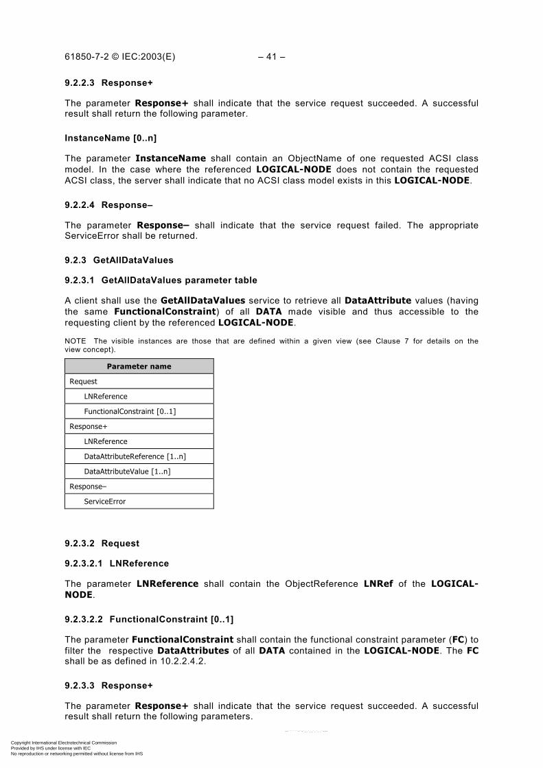
61850-7-2 © IEC:2003(E) – 41 –
9.2.2.3 Response+
The parameter Response+ shall indicate that the service request succeeded. A successfulresult shall return the following parameter.
InstanceName [0..n]
The parameter InstanceName shall contain an ObjectName of one requested ACSI classmodel. In the case where the referenced LOGICAL-NODE does not contain the requestedACSI class, the server shall indicate that no ACSI class model exists in this LOGICAL-NODE.
9.2.2.4 Response–
The parameter Response– shall indicate that the service request failed. The appropriateServiceError shall be returned.
9.2.3 GetAllDataValues
9.2.3.1 GetAllDataValues parameter table
A client shall use the GetAllDataValues service to retrieve all DataAttribute values (havingthe same FunctionalConstraint) of all DATA made visible and thus accessible to therequesting client by the referenced LOGICAL-NODE.
NOTE The visible instances are those that are defined within a given view (see Clause 7 for details on theview concept).
Parameter name
Request
LNReference
FunctionalConstraint [0..1]
Response+
LNReference
DataAttributeReference [1..n]
DataAttributeValue [1..n]
Response–
ServiceError
9.2.3.2 Request
9.2.3.2.1 LNReference
The parameter LNReference shall contain the ObjectReference LNRef of the LOGICAL-NODE.
9.2.3.2.2 FunctionalConstraint [0..1]
The parameter FunctionalConstraint shall contain the functional constraint parameter (FC) tofilter the respective DataAttributes of all DATA contained in the LOGICAL-NODE. The FCshall be as defined in 10.2.2.4.2.
9.2.3.3 Response+
The parameter Response+ shall indicate that the service request succeeded. A successfulresult shall return the following parameters.
Copyright International Electrotechnical Commission Provided by IHS under license with IEC
Not for ResaleNo reproduction or networking permitted without license from IHS
--``````-`-`,,`,,`,`,,`---
– 42 – 61850-7-2 IEC:2003(E)
9.2.3.3.1 DataAttributeReference [1..n]
The parameter DataAttributeReference shall contain the ObjectReference of aDataAttribute contained in the LOGICAL-NODE that shall be returned according to thevalue of the FunctionalConstraint received in the request.
NOTE The ObjectReference DataAttributeReference is defined in 10.2.2.4.
9.2.3.3.2 DataAttributeValue [1..n]
The parameter DataAttributeValue shall contain the value of a DataAttribute of the DATAcontained in the referenced LOGICAL-NODE. Only values of those DataAttributes that havethe functional constrained equal to the value of the parameter FunctionalConstraint in theservice request shall be returned.
9.2.3.4 Response–
The parameter Response– shall indicate that the service request failed. The appropriateServiceError shall be returned.
10 DATA class model
10.1 General
DATA classes represent meaningful information of applications located in an automationdevices. The values of DATA instances can, for example, be written (SetDataValues) andread (GetDataValues). IEC 61850-7-4 specifies a list of common and substation-domain-specific – simple and complex – DATA, for example, Pos for position, OilFil for oil filtration.The composition of DATA in IEC 61850-7-4 is based on common templates (the commonDATA classes, CDC) specified in IEC 61850-7-3. The concept of DATA classes is introduced inthis clause. Any set of DATA (or parts of DATA) instances may be grouped to build DATA-SETinstances applying the CreateDataSet service. DATA-SET instances can, for example, bewritten (SetDataSetValues) or read (GetDataSetValues)
NOTE 1 The consequences of setting values to instances of DATA is outside this part of IEC 61850. IEC 61850-7-3and IEC 61850-7-4 specify many substation-domain-specific DATA classes. These definitions provide informationon the actions to be taken by the receiving application, for example, changing the DATA Mode from ON to TESTchanges the state of the respective instance to test mode behaviour as defined in IEC 61850-7-4.
NOTE 2 The client queries values of DATA (DATA-SET) from a server using the service GetDataValues(GetDataSetValues). Services for unsolicited/spontaneous transmission of values of DATA from a server toclients (sometimes known as information report, traps, or spontaneous transmission) require a careful design.Uncontrolled spontaneous transmission may congest the network. Services for a controlled reporting are specifiedin Clause 14.
10.2 DATA class definition
10.2.1 DATA class syntax
The DATA class is a key element in IEC 61850. The class diagram in Figure 10 is intended asan introduction to the formal DATA class specification.
Copyright International Electrotechnical Commission Provided by IHS under license with IEC
Not for ResaleNo reproduction or networking permitted without license from IHS
--``````-`-`,,`,,`,`,,`---

61850-7-2 © IEC:2003(E) – 43 –
DATA
SimpleCDC
CompositeCDCDataNamePresence
DataAttributeFCTrgOps
0..n
1..n
DAType
PrimitiveComponent
CompositeComponentNamePresence
1..n
<<of type>>
BasicType
1
WYE
CMV
Vector
AnalogueValue
FLOAT32
Figure 10 – Class diagram of DATA and DataAttributeType
NOTE 1 The example in Figure 10 uses definitions (for example, WYE, CMV, Vector, and AnalogueValuecommon DATA classes) found in IEC 61850-7-3. A comprehensive introduction to the modelling of DATA can befound in IEC 61850-7-1.
The DATA is a class that has a DataName, an indication (Presence) if the DATA is mandatory(present) or optional (not-present), and DataAttributes.
NOTE 2 The DATA class is an abstract class that is an auxiliary means to construct the primitive and compositecommon data classes.
NOTE 3 The following examples used in the text refer to Figure 11.
The DataAttributes (for example, cVal – complex value) are used to build a SimpleCDC(simple common data class) and CompositeCDC (composite common data class).SimpleCDC shall have a DataName, a Presence, and DataAttributes (for example,DataName = phsA, Presence = Mandatory, and DataAttribute = cVal). The CompositeCDC isconstructed by one or more SimpleCDC and/or DataAttributes (for example, CDC WYEcomprising a SimpleCDC CMV, etc.).
The DAType has already been explained in 5.5.1.
Figure 11 depicts an excerpt of a DATA instance (contained in a LOGICAL-NODE MMXU1).The instance of the LOGICAL-NODE with the name MMXU1 (instantiated from MMXU) iscomposed of the instance of the DATA phase voltage named PhV (instantiated from WYE),which is composed of phase A voltage phsA (instantiated from CMV), which is composed ofcomplex value cVal (of type Vector), which is composed of voltage mag (of typeAnalogueValue), which is composed of floating-point value f (of type FLOAT32). TheDataAttribute has additionally the functional constraint FC = MX (measurand) and the triggeroption TrgOp = dchg (data-change).
IEC 405/03
Copyright International Electrotechnical Commission Provided by IHS under license with IEC
Not for ResaleNo reproduction or networking permitted without license from IHS
--``````-`-`,,`,,`,`,,`---

– 44 – 61850-7-2 IEC:2003(E)
CompatibleLN instance
MMXU1 MMXU
PhV WYE
phsA CMVcVal Vector [MX] [dchg]
MMXU1.PhVMMXU1.PhV [MX]MMXU1.PhV.PhsAMMXU1.PhV.PhsA.cValMMXU1.PhV.PhsA.cVal [MX]MMXU1.PhV.PhsA.cVal.magMMXU1.PhV.PhsA.cVal.mag.f
CompatibleDATA class(IEC 61850-7-4)
Composite CommonDATA class(IEC 61850-7-3)
DataAttribute
CompositeComponent(IEC 61850-7-3)
... ... ... mag AnalogueValue
... f FLOAT32
DataRefMX functionally constrained Data (FCD)DataRefDataAttrRefMX functionally constrained DataAttribute (FCDA)DAComponentRefDAComponentRef
Simple CommonDATA class(IEC 61850-7-3)
Compatible LN class(IEC 61850-7-4)
CompositeComponent(IEC 61850-7-3)
PrimitiveComponent(IEC 61850-7-3)
DataAttributeComponent
Instances
Classes/types
Common DataAttribute type(IEC 61850-7-3)
BasicType (IEC 61850-7-2)
DATA class(IEC 61850-7-3)
Figure 11 – Example of DATA
NOTE 4 The explanation of the DATA class refers to the example shown in Figure 11. The example uses somedefinitions from IEC 61850-7-3 just to demonstrate the formal definition of the DATA class. A complete definition ofthe compatible classes is defined in IEC 61850-7-3.
The references for the various levels are listed at the bottom of the figure.
The DATA shall have the structure defined in Table 16.
The inheritance and relations between the classes DATA, CompositeCDC, SimpleCDC, andDAType shall be as shown in Figure 10.
The table notation does not easily show the inheritance. Therefore the class diagram inFigure 10 shall be normative. The tables and the class diagrams shall be used together.
IEC 406/03
Copyright International Electrotechnical Commission Provided by IHS under license with IEC
Not for ResaleNo reproduction or networking permitted without license from IHS
--``````-`-`,,`,,`,`,,`---
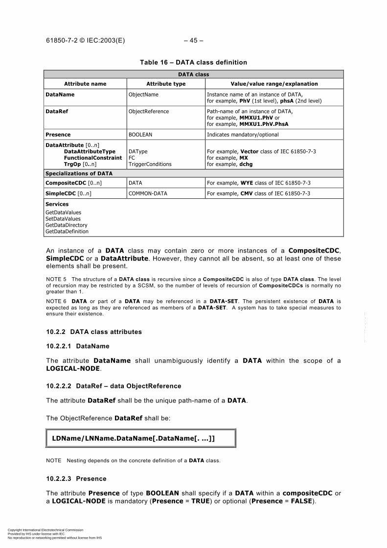
61850-7-2 © IEC:2003(E) – 45 –
Table 16 – DATA class definition
DATA class
Attribute name Attribute type Value/value range/explanation
DataName ObjectName Instance name of an instance of DATA,for example, PhV (1st level), phsA (2nd level)
DataRef ObjectReference Path-name of an instance of DATA,for example, MMXU1.PhV orfor example, MMXU1.PhV.PhsA
Presence BOOLEAN Indicates mandatory/optional
DataAttribute [0..n]DataAttributeTypeFunctionalConstraintTrgOp [0..n]
DATypeFCTriggerConditions
For example, Vector class of IEC 61850-7-3for example, MXfor example, dchg
Specializations of DATA
CompositeCDC [0..n] DATA For example, WYE class of IEC 61850-7-3
SimpleCDC [0..n] COMMON-DATA For example, CMV class of IEC 61850-7-3
ServicesGetDataValuesSetDataValuesGetDataDirectoryGetDataDefinition
An instance of a DATA class may contain zero or more instances of a CompositeCDC,SimpleCDC or a DataAttribute. However, they cannot all be absent, so at least one of theseelements shall be present.
NOTE 5 The structure of a DATA class is recursive since a CompositeCDC is also of type DATA class. The levelof recursion may be restricted by a SCSM, so the number of levels of recursion of CompositeCDCs is normally nogreater than 1.
NOTE 6 DATA or part of a DATA may be referenced in a DATA-SET. The persistent existence of DATA isexpected as long as they are referenced as members of a DATA-SET. A system has to take special measures toensure their existence.
10.2.2 DATA class attributes
10.2.2.1 DataName
The attribute DataName shall unambiguously identify a DATA within the scope of aLOGICAL-NODE.
10.2.2.2 DataRef – data ObjectReference
The attribute DataRef shall be the unique path-name of a DATA.
The ObjectReference DataRef shall be:
LDName/LNName.DataName[.DataName[. ...]]
NOTE Nesting depends on the concrete definition of a DATA class.
10.2.2.3 Presence
The attribute Presence of type BOOLEAN shall specify if a DATA within a compositeCDC ora LOGICAL-NODE is mandatory (Presence = TRUE) or optional (Presence = FALSE).
Copyright International Electrotechnical Commission Provided by IHS under license with IEC
Not for ResaleNo reproduction or networking permitted without license from IHS
--``````-`-`,,`,,`,`,,`---

– 46 – 61850-7-2 IEC:2003(E)
10.2.2.4 DataAttribute
10.2.2.4.1 DataAttributeType
10.2.2.4.1.1 General
The attribute DataAttributeType of type DAType shall specify a data attribute.
10.2.2.4.1.2 DAType syntax
The DAType shall be as defined in Table 17.
Table 17 – DAType definition
DAType
Attribute name Attribute type Value/value range/explanation
DATName ObjectName Instance name of an instance of DAType,for example, cVal (1st level), mag (2nd level), f (3rdlevel)
DATRef ObjectReference Path-name of an instance of DATypefor example, MMXU1.PhV.phsA.cValfor example, MMXU1.PhV.phsA.cVal.mag orfor example, MMXU1.PhV.phsA.cVal.mag.f
Presence BOOLEAN Indicates mandatory/optional
Specializations of DAType
CompositeComponent [0..n] DAType For example, mag in Vector class of IEC 61850-7-3for example, f in AnalogueValue of IEC 61850-7-3
PrimitiveComponent [0..1] BasicType For example, FLOAT32 class of IEC 61850-7-3 for f
NOTE 1 An instance of a DAType may contain 0 or more instances of a CompositeComponent or a PrimitveDAT.However, they cannot both be absent, so at least one of these elements must be present.
NOTE 2 The structure of a DAType is recursive since a CompositeComponent is also of type DAType. The levelof recursion may be restricted by a SCSM, so the number of levels of recursion of CompositeComponents isnormally no greater than 2.
DATName – data attribute type name
The attribute DATName shall unambiguously identify a DAType within the scope of aDataAttribute or a nested DataAttribute.
The DATName (if DataAttribute is not nested) or the DATName of the first level (if DataAttribute is nested) shall be called the DataAttributeName.
For the second and any deeper nesting levels the DATName shall be calledDAComponentName.
The ObjectReference from the top (LD) down to the DataAttributeName shall be calledDataAttributeReference.
EXAMPLE As shown in Figure 11, the cVal (derived from a common data attribute type – Vector) isthe DataAttribute. The mag (also derived from a common data attribute type – AnalogueValue) is aDataAttributeComponent.
Copyright International Electrotechnical Commission Provided by IHS under license with IEC
Not for ResaleNo reproduction or networking permitted without license from IHS
--``````-`-`,,`,,`,`,,`---
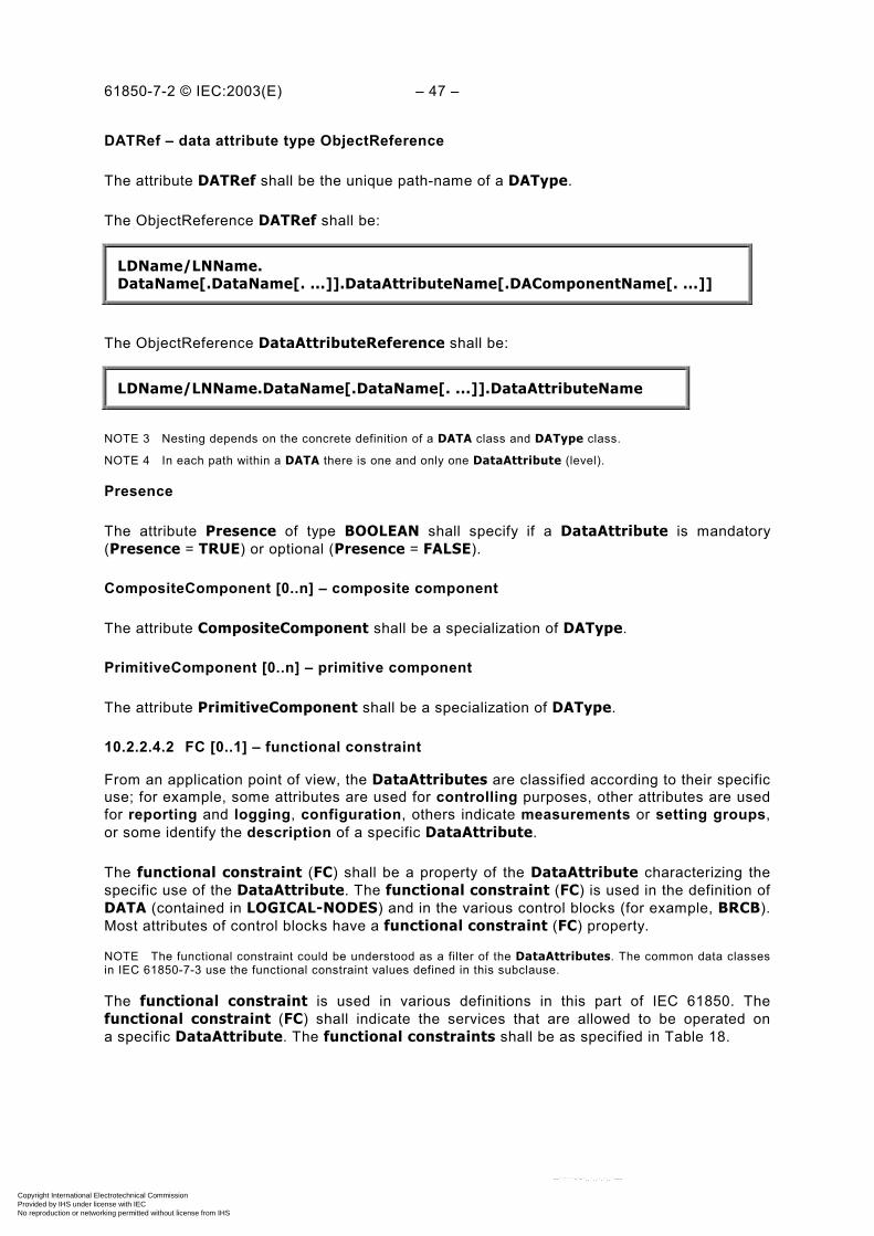
61850-7-2 © IEC:2003(E) – 47 –
DATRef – data attribute type ObjectReference
The attribute DATRef shall be the unique path-name of a DAType.
The ObjectReference DATRef shall be:
LDName/LNName.DataName[.DataName[. ...]].DataAttributeName[.DAComponentName[. ...]]
The ObjectReference DataAttributeReference shall be:
LDName/LNName.DataName[.DataName[. ...]].DataAttributeName
NOTE 3 Nesting depends on the concrete definition of a DATA class and DAType class.
NOTE 4 In each path within a DATA there is one and only one DataAttribute (level).
Presence
The attribute Presence of type BOOLEAN shall specify if a DataAttribute is mandatory(Presence = TRUE) or optional (Presence = FALSE).
CompositeComponent [0..n] – composite component
The attribute CompositeComponent shall be a specialization of DAType.
PrimitiveComponent [0..n] – primitive component
The attribute PrimitiveComponent shall be a specialization of DAType.
10.2.2.4.2 FC [0..1] – functional constraint
From an application point of view, the DataAttributes are classified according to their specificuse; for example, some attributes are used for controlling purposes, other attributes are usedfor reporting and logging, configuration, others indicate measurements or setting groups,or some identify the description of a specific DataAttribute.
The functional constraint (FC) shall be a property of the DataAttribute characterizing thespecific use of the DataAttribute. The functional constraint (FC) is used in the definition ofDATA (contained in LOGICAL-NODES) and in the various control blocks (for example, BRCB).Most attributes of control blocks have a functional constraint (FC) property.
NOTE The functional constraint could be understood as a filter of the DataAttributes. The common data classesin IEC 61850-7-3 use the functional constraint values defined in this subclause.
The functional constraint is used in various definitions in this part of IEC 61850. Thefunctional constraint (FC) shall indicate the services that are allowed to be operated ona specific DataAttribute. The functional constraints shall be as specified in Table 18.
Copyright International Electrotechnical Commission Provided by IHS under license with IEC
Not for ResaleNo reproduction or networking permitted without license from IHS
--``````-`-`,,`,,`,`,,`---
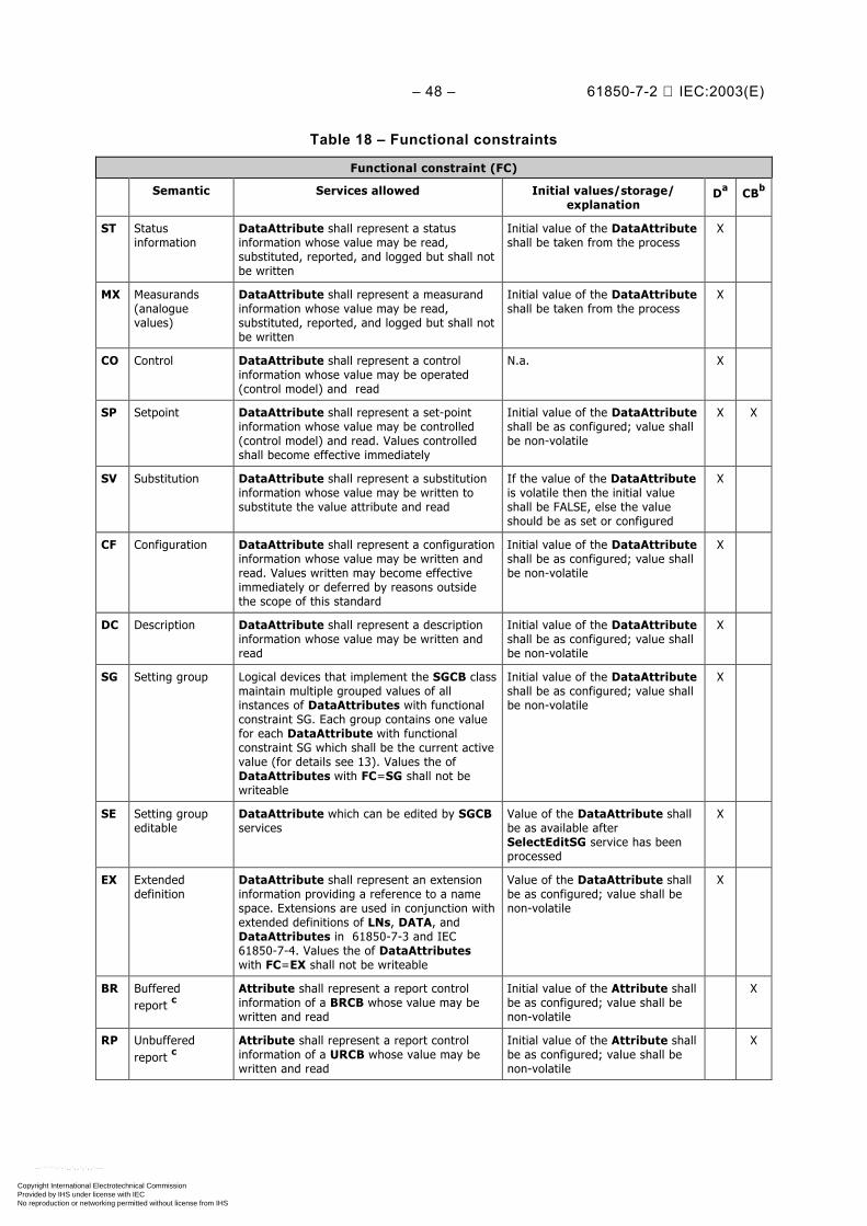
– 48 – 61850-7-2 IEC:2003(E)
Table 18 – Functional constraints
Functional constraint (FC)
Semantic Services allowed Initial values/storage/explanation
Da CBb
ST Statusinformation
DataAttribute shall represent a statusinformation whose value may be read,substituted, reported, and logged but shall notbe written
Initial value of the DataAttributeshall be taken from the process
X
MX Measurands(analoguevalues)
DataAttribute shall represent a measurandinformation whose value may be read,substituted, reported, and logged but shall notbe written
Initial value of the DataAttributeshall be taken from the process
X
CO Control DataAttribute shall represent a controlinformation whose value may be operated(control model) and read
N.a. X
SP Setpoint DataAttribute shall represent a set-pointinformation whose value may be controlled(control model) and read. Values controlledshall become effective immediately
Initial value of the DataAttributeshall be as configured; value shallbe non-volatile
X X
SV Substitution DataAttribute shall represent a substitutioninformation whose value may be written tosubstitute the value attribute and read
If the value of the DataAttributeis volatile then the initial valueshall be FALSE, else the valueshould be as set or configured
X
CF Configuration DataAttribute shall represent a configurationinformation whose value may be written andread. Values written may become effectiveimmediately or deferred by reasons outsidethe scope of this standard
Initial value of the DataAttributeshall be as configured; value shallbe non-volatile
X
DC Description DataAttribute shall represent a descriptioninformation whose value may be written andread
Initial value of the DataAttributeshall be as configured; value shallbe non-volatile
X
SG Setting group Logical devices that implement the SGCB classmaintain multiple grouped values of allinstances of DataAttributes with functionalconstraint SG. Each group contains one valuefor each DataAttribute with functionalconstraint SG which shall be the current activevalue (for details see 13). Values the ofDataAttributes with FC=SG shall not bewriteable
Initial value of the DataAttributeshall be as configured; value shallbe non-volatile
X
SE Setting groupeditable
DataAttribute which can be edited by SGCBservices
Value of the DataAttribute shallbe as available afterSelectEditSG service has beenprocessed
X
EX Extendeddefinition
DataAttribute shall represent an extensioninformation providing a reference to a namespace. Extensions are used in conjunction withextended definitions of LNs, DATA, andDataAttributes in 61850-7-3 and IEC61850-7-4. Values the of DataAttributeswith FC=EX shall not be writeable
Value of the DataAttribute shallbe as configured; value shall benon-volatile
X
BR Bufferedreport c
Attribute shall represent a report controlinformation of a BRCB whose value may bewritten and read
Initial value of the Attribute shallbe as configured; value shall benon-volatile
X
RP Unbufferedreport c
Attribute shall represent a report controlinformation of a URCB whose value may bewritten and read
Initial value of the Attribute shallbe as configured; value shall benon-volatile
X
Copyright International Electrotechnical Commission Provided by IHS under license with IEC
Not for ResaleNo reproduction or networking permitted without license from IHS
--``````-`-`,,`,,`,`,,`---

61850-7-2 © IEC:2003(E) – 49 –
Semantic Services allowed Initial values/storage/explanation
Da CBb
LG Logging c Attribute shall represent a log controlinformation of a LCB whose value may bewritten and read
Initial value of the Attribute shallbe as configured; value shall benon-volatile
X
GO Goose control c Attribute shall represent a goose controlinformation of a GoCB whose value may bewritten and read
Initial value of the Attribute shallbe as configured; value shall benon-volatile
X
GS Gsse control c Attribute shall represent a goose controlinformation of a GsCB whose value may bewritten and read
Initial value of the Attribute shallbe as configured; value shall benon-volatile
X
MS Multicastsampled valuecontrol c
Attribute shall represent a sampled valuecontrol information of a MSVCB whose valuemay be written and read
Initial value of the Attribute shallbe as configured; value shall benon-volatile
X
US Unicast sampledvalue control c
Attribute shall represent a sampled valuecontrol information of an instance of aUNICAST-SVC whose value may be written andread
Initial value of the Attribute shallbe as configured; value shall benon-volatile
X
XX Representing allDataAttributesas a serviceparameter
Shall represent all DataAttributes of a DATA(of any FC) to be accessed, for example, to bewritten and read. The FC value “xx” shall onlybe used in the functionally constrained data(FCD); “XX” shall not be used as FC valuein a DataAttribute
“XX” shall be used as a wildcard in servicesonly
NOTE The possibility to write an Attribute or a DataAttribute may be further constrained bya view or an implementation.a Column D indicates the use of the FC in the definition of DATA (i.e. common DATA classes in IEC 61850-7-3).b Column CB indicates the use of the FC in the definition of control blocks in this part of IEC 61850.c Reserved for control classes in this part of IEC 61850.
EXAMPLE The common data attribute for the common data class single-point status (SPS) according toIEC 61850-7-3 has the following DataAttributes: stVal (status value), q (quality), and t (time stamp) with thefunctional constraint ST (status information).
10.2.2.4.3 TrgOp [0..n] – trigger option
The attribute TrgOp of type TriggerConditions (see Table 10) shall specify the triggerconditions (associated with a DataAttribute of a DATA) that may cause a report to be sent ora log entry to be stored into a log (report model; see Clause 14). The services associated withthe TriggerConditions shall be as specified in Table 19.
Table 19 – Trigger option
TrgOp Semantic Services allowed
dchg data-change A report or a log entry shall be generated due to a change of the value ofthe data attribute
qchg quality-change A report or a log entry shall be generated due to a change of the value ofthe quality attribute
dupd data value update A report or a log entry shall be generated due to freezing the value ofa freezable attribute or updating the value of any other attribute. Anupdated value may have the same value as the old value
NOTE The trigger conditions integrity and general-interrogation of the TriggerConditions type (see Table 10) are usedindependent of instances of DATA; they can be set from remote by services and thus trigger sending reports or placinglog entries into logs.
Copyright International Electrotechnical Commission Provided by IHS under license with IEC
Not for ResaleNo reproduction or networking permitted without license from IHS
--``````-`-`,,`,,`,`,,`---
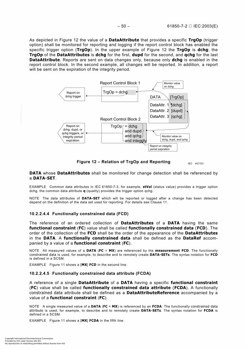
– 50 – 61850-7-2 IEC:2003(E)
As depicted in Figure 12 the value of a DataAttribute that provides a specific TrgOp (triggeroption) shall be monitored for reporting and logging if the report control block has enabled thespecific trigger option (TrgOp). In the upper example of Figure 12 the TrgOp is dchg; theTrgOp of the DataAttributes is dchg for the first, dupd for the second, and qchg for the lastDataAttribute. Reports are sent on data changes only, because only dchg is enabled in thereport control block. In the second example, all changes will be reported. In addition, a reportwill be sent on the expiration of the integrity period.
DATA
DataAttr. 1 [dchg]DataAttr. 2 [dupd]DataAttr. 3 [qchg]
[TrgOp]
Report Control Block 1
TrgOp = dchg
Report Control Block 2
TrgOp = dchgand dupdand qchgand integrity
Report ondchg, dupd, or
qchg triggers, orintegrity period
expiration
Report ondchg trigger
Monitor value ondchg, dupd, and qchg
Report on integrityperiod expiration
Monitor valueon dchg
Figure 12 – Relation of TrgOp and Reporting
DATA whose DataAttributes shall be monitored for change detection shall be referenced bya DATA-SET.
EXAMPLE Common data attributes in IEC 61850-7-3, for example, stVal (status value) provides a trigger optiondchg, the common data attribute q (quality) provides the trigger option qchg.
NOTE The data attributes of DATA-SET which will be reported or logged after a change has been detecteddepend on the definition of the data set used for reporting. For details see Clause 11.
10.2.2.4.4 Functionally constrained data (FCD)
The reference of an ordered collection of DataAttributes of a DATA having the samefunctional constraint (FC) value shall be called functionally constrained data (FCD). Theorder of the collection of the FCD shall be the order of the appearance of the DataAttributesin the DATA. A functionally constrained data shall be defined as the DataRef accom-panied by a value of a functional constraint (FC).
NOTE All measured values of a DATA (FC = MX) are referenced by the measurement FCD. The functionallyconstrained data is used, for example, to describe and to remotely create DATA-SETs. The syntax notation for FCDis defined in a SCSM.
EXAMPLE Figure 11 shows a [MX] FCD in the second line.
10.2.2.4.5 Functionally constrained data attribute (FCDA)
A reference of a single DataAttribute of a DATA having a specific functional constraint(FC) value shall be called functionally constrained data attribute (FCDA). A functionallyconstrained data attribute shall be defined as a DataAttributeReference accompanied by avalue of a functional constraint (FC).
NOTE A single measured value of a DATA (FC = MX) is referenced by an FCDA. The functionally constrained dataattribute is used, for example, to describe and to remotely create DATA-SETs. The syntax notation for FCDA isdefined in a SCSM.
EXAMPLE Figure 11 shows a [MX] FCDA in the fifth line.
IEC 407/03
Copyright International Electrotechnical Commission Provided by IHS under license with IEC
Not for ResaleNo reproduction or networking permitted without license from IHS
--``````-`-`,,`,,`,`,,`---

61850-7-2 © IEC:2003(E) – 51 –
10.2.2.5 CompositeCDC [0..n]
The attribute CompositeCDC shall be a specialization of DATA.
10.2.2.6 SimpleCDC [0..n]
10.2.2.6.1 SimpleCDC syntax – General
The attribute SimpleCDC shall be a specialization of DATA.
10.2.2.6.2 COMMON-DATA class syntax
The COMMON-DATA class shall be as defined in Table 20.
Table 20 – COMMON-DATA class definition
COMMON-DATA class
Attribute Name Attribute Type Value/value range/explanation
DataName ObjectName Instance name of an instance of DATA,for example, PhV (1st level), phsA (2nd level),
DataRef ObjectReference Path-name of an instance of DATA,for example, MMXU1.PhV orfor example, MMXU1.PhV.phsA
Presence BOOLEAN Indicates mandatory/optional
DataAttribute [1..n]DataAttributeTypeFunctionalConstraintTrgOp [0..n]
DATypeFCTriggerConditions
For example, Vector class of IEC 61850-7-3for example, MXfor example, dchg
ServicesGetDataValueSetDataValueGetDataDirectoryGetDataDefinition
NOTE 1 The CommonDATA is a subclass of the DATA class.
NOTE 2 DATA or DataAttribute may be referenced in a DATA-SET. The persistent existence of DATA andDataAttribute is expected as long as they are referenced as members of a DATA-SET. A system has to takespecial measures to ensure their existence.
NOTE 3 IEC 61850-7-2 defines the basic class model. IEC 61850-7-3 defines specialized DATA classes – thecommon DATA classes, for example, SPS modelling a single-point status DATA class. IEC 61850-7-4 definesspecialized common DATA classes – the compatible DATA classes, for example, Pos modelling a position(specializing a SPS common DATA class).
DataName
The attribute DataName shall identify a DATA within the scope of a LOGICAL-NODE or anested DATA.
DataRef – data ObjectReference
The attribute DataRef shall be the unique path-name of a DATA.
The ObjectReference DataRef shall be:
LDName/LNName.DataName[.DataName[. ...]]
NOTE Nesting depends on the concrete definition of a DATA class.
Copyright International Electrotechnical Commission Provided by IHS under license with IEC
Not for ResaleNo reproduction or networking permitted without license from IHS
--``````-`-`,,`,,`,`,,`---
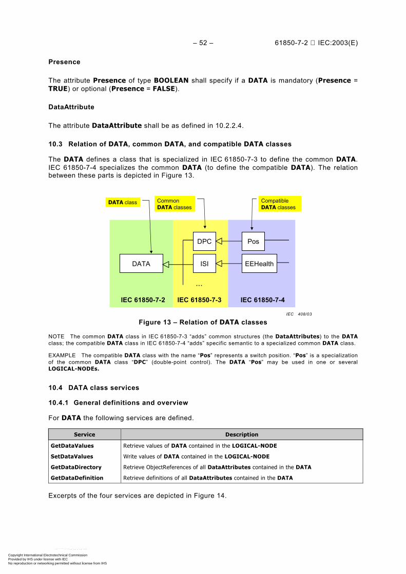
– 52 – 61850-7-2 IEC:2003(E)
Presence
The attribute Presence of type BOOLEAN shall specify if a DATA is mandatory (Presence =TRUE) or optional (Presence = FALSE).
DataAttribute
The attribute DataAttribute shall be as defined in 10.2.2.4.
10.3 Relation of DATA, common DATA, and compatible DATA classes
The DATA defines a class that is specialized in IEC 61850-7-3 to define the common DATA.IEC 61850-7-4 specializes the common DATA (to define the compatible DATA). The relationbetween these parts is depicted in Figure 13.
DATA
DPC
EEHealth
Pos
ISI
...
IEC 61850-7-2 IEC 61850-7-3 IEC 61850-7-4
CompatibleDATA classes
CommonDATA classes
DATA class
Figure 13 – Relation of DATA classes
NOTE The common DATA class in IEC 61850-7-3 “adds” common structures (the DataAttributes) to the DATAclass; the compatible DATA class in IEC 61850-7-4 “adds” specific semantic to a specialized common DATA class.
EXAMPLE The compatible DATA class with the name “Pos” represents a switch position. “Pos” is a specializationof the common DATA class “DPC” (double-point control). The DATA “Pos” may be used in one or severalLOGICAL-NODEs.
10.4 DATA class services
10.4.1 General definitions and overview
For DATA the following services are defined.
Service Description
GetDataValues Retrieve values of DATA contained in the LOGICAL-NODE
SetDataValues Write values of DATA contained in the LOGICAL-NODE
GetDataDirectory Retrieve ObjectReferences of all DataAttributes contained in the DATA
GetDataDefinition Retrieve definitions of all DataAttributes contained in the DATA
Excerpts of the four services are depicted in Figure 14.
IEC 408/03
Copyright International Electrotechnical Commission Provided by IHS under license with IEC
Not for ResaleNo reproduction or networking permitted without license from IHS
--``````-`-`,,`,,`,`,,`---
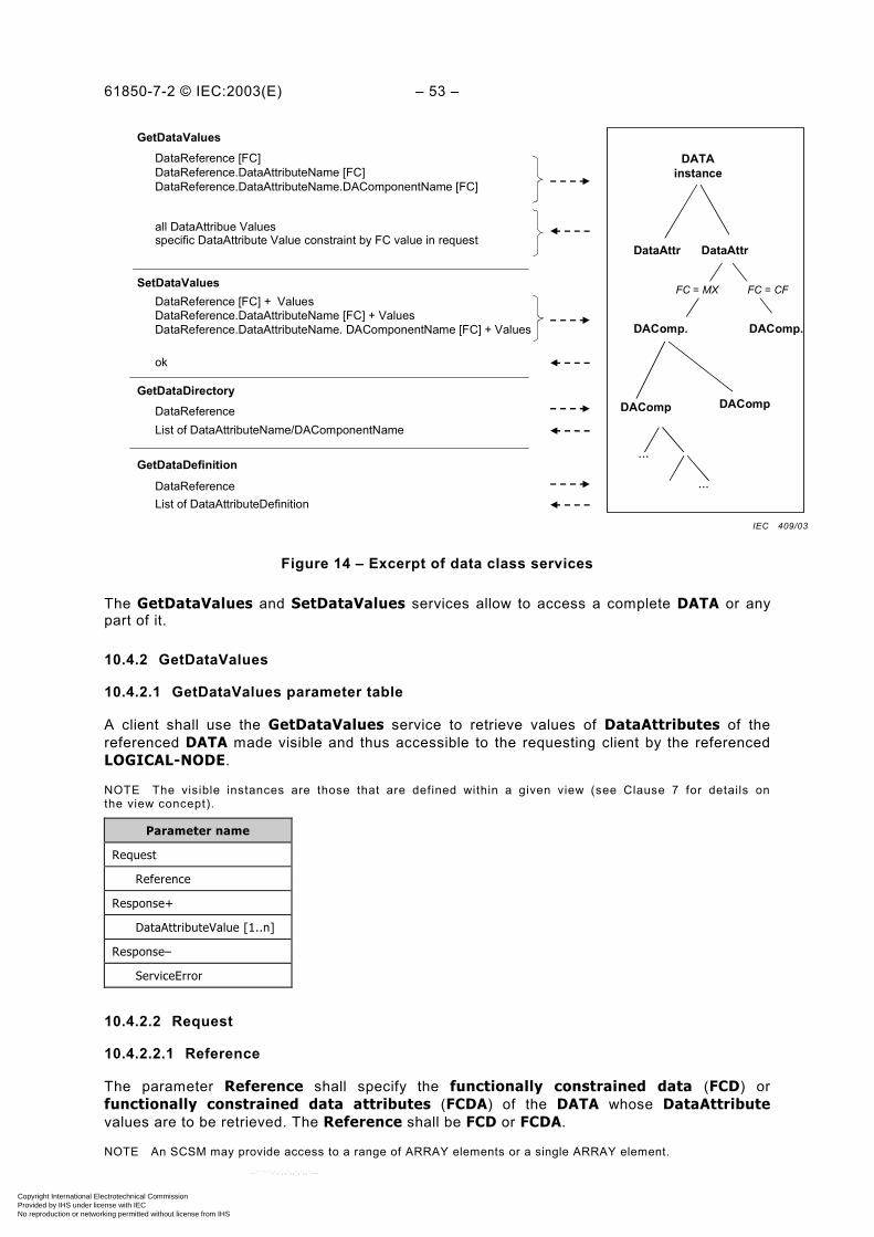
61850-7-2 © IEC:2003(E) – 53 –
DATAinstance
DAComp.
GetDataDirectory
List of DataAttributeName/DAComponentName
GetDataDefinition
DataReferenceList of DataAttributeDefinition
GetDataValuesDataReference [FC]DataReference.DataAttributeName [FC]DataReference.DataAttributeName.DAComponentName [FC]
all DataAttribue Valuesspecific DataAttribute Value constraint by FC value in request
SetDataValues
DataReference
DataAttr DataAttr
DAComp.
DataReference [FC] + ValuesDataReference.DataAttributeName [FC] + ValuesDataReference.DataAttributeName. DAComponentName [FC] + Values
ok
DAComp DAComp
...
...
FC = MX FC = CF
Figure 14 – Excerpt of data class services
The GetDataValues and SetDataValues services allow to access a complete DATA or anypart of it.
10.4.2 GetDataValues
10.4.2.1 GetDataValues parameter table
A client shall use the GetDataValues service to retrieve values of DataAttributes of thereferenced DATA made visible and thus accessible to the requesting client by the referencedLOGICAL-NODE.
NOTE The visible instances are those that are defined within a given view (see Clause 7 for details onthe view concept).
Parameter name
Request
Reference
Response+
DataAttributeValue [1..n]
Response–
ServiceError
10.4.2.2 Request
10.4.2.2.1 Reference
The parameter Reference shall specify the functionally constrained data (FCD) orfunctionally constrained data attributes (FCDA) of the DATA whose DataAttributevalues are to be retrieved. The Reference shall be FCD or FCDA.
NOTE An SCSM may provide access to a range of ARRAY elements or a single ARRAY element.
IEC 409/03
Copyright International Electrotechnical Commission Provided by IHS under license with IEC
Not for ResaleNo reproduction or networking permitted without license from IHS
--``````-`-`,,`,,`,`,,`---

– 54 – 61850-7-2 IEC:2003(E)
10.4.2.3 Response+
The parameter Response+ shall indicate that the service request succeeded. A successfulresult shall return the following parameter.
10.4.2.3.1 DataAttributeValue [1..n]
The parameter DataAttributeValue shall contain
– the values of all DataAttributes of a DATA referenced by FCD; or
– the value of a DataAttribute referenced by FCDA.
NOTE The syntax of the DataAtributeValue is defined in an SCSM.
10.4.2.4 Response–
The parameter Response– shall indicate that the service request failed. The appropriateServiceError shall be returned.
10.4.3 SetDataValues
10.4.3.1 SetDataValues parameter table
A client shall use the SetDataValues service to set values of DataAttributes of thereferenced DATA made visible and thus accessible to the requesting client by the referencedLOGICAL-NODE.
NOTE The visible instances are those that are defined within a given view (see Clause 7 for details onthe view concept).
Parameter name
Request
Reference
DataAttributeValue [1..n]
Response+
Response–
ServiceError
10.4.3.2 Request
10.4.3.2.1 Reference
The parameter Reference shall specify the functionally constrained data (FCD) orfunctionally constrained data attributes (FCDA) of the DATA whose DataAttributevalues are to be retrieved. The Reference shall be FCD or FCDA.
NOTE An SCSM may provide access to a range of ARRAY elements or a single ARRAY element.
10.4.3.2.2 DataAttributeValue [1..n]
The parameter DataAttributeValue shall contain
– the values of all DataAttributes of a DATA referenced by FCD; or
– the value of a DataAttribute referenced by FCDA.
NOTE The syntax of the DataAtributeValue is defined in an SCSM.
Copyright International Electrotechnical Commission Provided by IHS under license with IEC
Not for ResaleNo reproduction or networking permitted without license from IHS
--``````-`-`,,`,,`,`,,`---

61850-7-2 © IEC:2003(E) – 55 –
10.4.3.3 Response+
The parameter Response+ shall indicate that the service request succeeded.
NOTE 1 For the SetDataValues service, a successful result means that the service request was acceptable tothe server and that the server has attempted to move the value of each DataAttribute of the DATA requested bythe service to the corresponding application.
NOTE 2 The action to be taken by an application receiving the value for a DATA to be set is outside the scope ofthis standard.
10.4.3.4 Response–
The parameter Response– shall indicate that the service request failed. The appropriateServiceError shall be returned.
10.4.4 GetDataDirectory
10.4.4.1 GetDataDirectory parameter table
A client shall use the GetDataDirectory service to retrieve the list of allDataAttributeNames of the referenced DATA made visible and thus accessible tothe requesting client by the referenced LOGICAL-NODE.
NOTE The visible instances are those that are defined within a given view (see Clause 7 for details on theview concept).
Parameter name
Request
DataReference
Response+
DataAttributeName [1..n]
Response–
ServiceError
10.4.4.2 Request
DataReference – data reference
The parameter DataReference shall contain the ObjectReference of a DATA. TheObjectReference shall be DataRef.
10.4.4.3 Response+
The parameter Response+ shall indicate that the service request succeeded. A successfulresult shall return the following parameter.
DataAttributeName [1..n]
The parameter DataAttributeName shall contain a DataAttrName of the highest level of aDataAttribute of the DATA.
10.4.4.4 Response–
The parameter Response– shall indicate that the service request failed. The appropriateServiceError shall be returned.
Copyright International Electrotechnical Commission Provided by IHS under license with IEC
Not for ResaleNo reproduction or networking permitted without license from IHS
--``````-`-`,,`,,`,`,,`---

– 56 – 61850-7-2 IEC:2003(E)
10.4.5 GetDataDefinition
10.4.5.1 GetDataDefinition parameter table
A client shall use the GetDataDefinition service to retrieve the complete list of allDataAttribute definitions of the referenced DATA made visible and thus accessible to therequesting client by the referenced LOGICAL-NODE.
NOTE 1 Complete means that the whole structure (the tree with all its branches and leaves) of eachDataAttribute shall be retrieved, i.e., all nested DataAttribute.
NOTE 2 The visible instances are those that are defined within a given view (see Clause 7 for details onthe view concept).
Parameter name
Request
DataReference
Response+
DataAttributeDefinition
Response–
ServiceError
10.4.5.2 Request
DataReference – data ObjectReference
The parameter DataReference shall contain the ObjectReference of the DATA. TheObjectReference shall be DataRef.
NOTE An SCSM may bundle several DataReference parameters into one message.
10.4.5.3 Response+
DataAttributeDefinition
The parameter DataAttributeDefinition shall contain a DataAttrName and DataAttrTypeof the first level and of all nested levels below of the referenced DATA and the functionalconstraints of each DataAttribute where applicable.
10.4.5.4 Response–
The parameter Response– shall indicate that the service request failed. The appropriateServiceError shall be returned.
11 DATA-SET class model
11.1 General
A DATA-SET is an ordered group of ObjectReferences of DATA or DataAttributes (calledthe data set members), organized as a single collection for the convenience of the client. Themembership and order of the ObjectReferences in a DATA-SET shall be known to boththe client and the server, so that only the name of the DATA-SET and the current values of thereferenced DATA or DataAttributes need to be transmitted. This capability thus permits moreefficient use of the communications bandwidth.
NOTE 1 The membership and order of the DATA or DataAttribute in a DATA-SET can be retrieved with theGetDataSetDirectory service. The persistent existence of DATA and DataAttribute is expected as long as theyare referenced as members of a DATA-SET. A system has to take special measures to ensure their persistentexistence.
Copyright International Electrotechnical Commission Provided by IHS under license with IEC
Not for ResaleNo reproduction or networking permitted without license from IHS
--``````-`-`,,`,,`,`,,`---
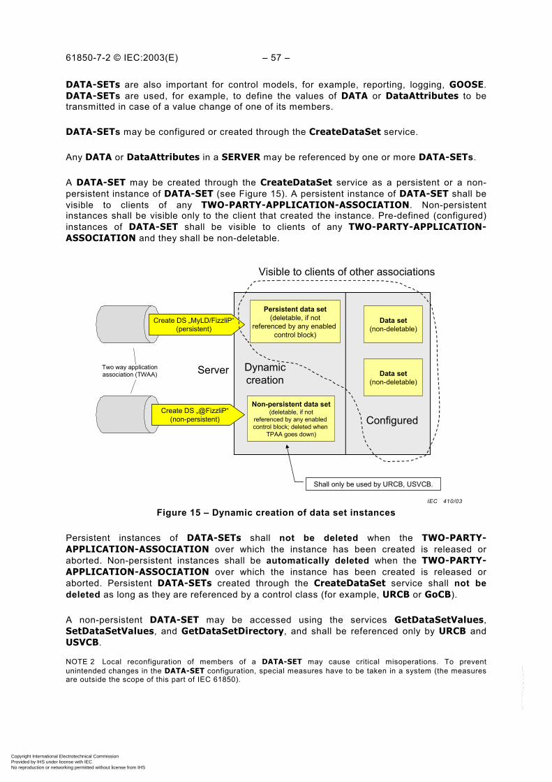
61850-7-2 © IEC:2003(E) – 57 –
DATA-SETs are also important for control models, for example, reporting, logging, GOOSE.DATA-SETs are used, for example, to define the values of DATA or DataAttributes to betransmitted in case of a value change of one of its members.
DATA-SETs may be configured or created through the CreateDataSet service.
Any DATA or DataAttributes in a SERVER may be referenced by one or more DATA-SETs.
A DATA-SET may be created through the CreateDataSet service as a persistent or a non-persistent instance of DATA-SET (see Figure 15). A persistent instance of DATA-SET shall bevisible to clients of any TWO-PARTY-APPLICATION-ASSOCIATION. Non-persistentinstances shall be visible only to the client that created the instance. Pre-defined (configured)instances of DATA-SET shall be visible to clients of any TWO-PARTY-APPLICATION-ASSOCIATION and they shall be non-deletable.
Create DS „MyLD/FizzliP“(persistent)
Persistent data set(deletable, if not
referenced by any enabled control block)
Non-persistent data set(deletable, if not
referenced by any enabled control block; deleted when
TPAA goes down)
Data set(non-deletable)
Configured
Visible to clients of other associations
Data set(non-deletable)
Create DS „@FizzliP“(non-persistent)
Shall only be used by URCB, USVCB.
Dynamiccreation
Two way applicationassociation (TWAA) Server
Figure 15 – Dynamic creation of data set instances
Persistent instances of DATA-SETs shall not be deleted when the TWO-PARTY-APPLICATION-ASSOCIATION over which the instance has been created is released oraborted. Non-persistent instances shall be automatically deleted when the TWO-PARTY-APPLICATION-ASSOCIATION over which the instance has been created is released oraborted. Persistent DATA-SETs created through the CreateDataSet service shall not bedeleted as long as they are referenced by a control class (for example, URCB or GoCB).
A non-persistent DATA-SET may be accessed using the services GetDataSetValues,SetDataSetValues, and GetDataSetDirectory, and shall be referenced only by URCB andUSVCB.
NOTE 2 Local reconfiguration of members of a DATA-SET may cause critical misoperations. To preventunintended changes in the DATA-SET configuration, special measures have to be taken in a system (the measuresare outside the scope of this part of IEC 61850).
IEC 410/03
Copyright International Electrotechnical Commission Provided by IHS under license with IEC
Not for ResaleNo reproduction or networking permitted without license from IHS
--``````-`-`,,`,,`,`,,`---

– 58 – 61850-7-2 IEC:2003(E)
11.2 DATA-SET class definition
11.2.1 DATA-SET class syntax
The DATA-SET shall have the structure as defined in Table 21.
Table 21 – DATA-SET (DS) class definition
DATA-SET class
Attribute name Attribute type Value/value range/explanation
DSName ObjectName Instance name of an instance of DATA-SET
DSRef ObjectReference Path-name of an instance of DATA-SET
DSMemberRef [1..n] (*) (*) Functionally constrained data (FCD) or functionallyconstrained data attribute (FCDA)
ServicesGetDataSetValuesSetDataSetValuesCreateDataSetDeleteDataSetGetDataSetDirectory
11.2.2 DATA-SET class attributes
11.2.2.1 DSName
The attribute DSName shall unambiguously identify DATA-SET within the scope of aLOGICAL-NODE or within a two-party-application-association.
11.2.2.2 DSRef
The attribute DSRef shall be the unique path-name of an instance of DATA-SET.
The ObjectReference DSRef shall be one of the following two options.
LDName/LNName.DataSetName To reference a persistent instance of DATA-SET
@DataSetName To reference a non-persistent instance of DATA-SET
11.2.2.3 DSMemberRef [1..n] – data set member reference
The attribute DSMemberRef shall specify the functionally constrained data (FCD) orfunctionally constrained data attribute (FCDA) of DATA.
The value of a member of a DATA-SET retrieved, set, reported, or logged shall be determinedby the functionally constrained DATA (FCD) or functionally constrained data attribute (FCDA).
NOTE A DATA-SET does not contain DATA. A DATA-SET contains references, the functionally constrained data(FCD) or functionally constrained data attribute (FCDA). A DATA-SET may contain references to functionallyconstrained DATA (FCD) or functionally constrained data attribute (FCDA) contained in different LOGICAL-NODEs.
Copyright International Electrotechnical Commission Provided by IHS under license with IEC
Not for ResaleNo reproduction or networking permitted without license from IHS
--``````-`-`,,`,,`,`,,`---
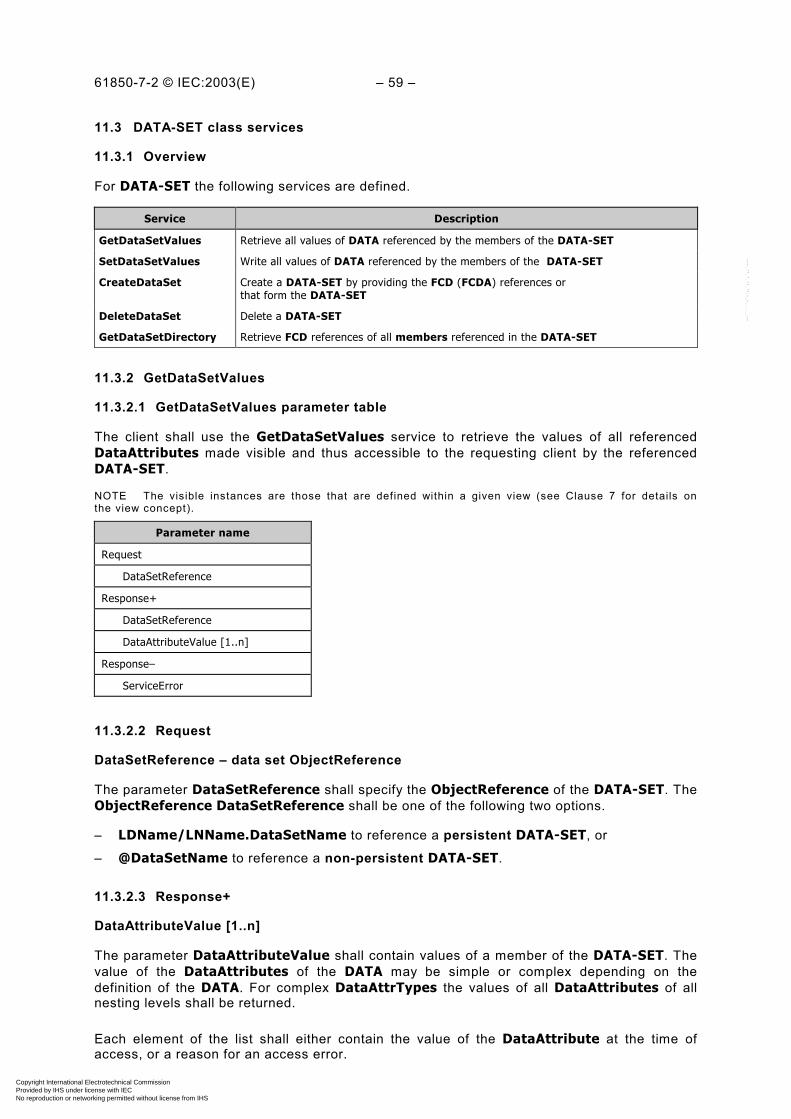
61850-7-2 © IEC:2003(E) – 59 –
11.3 DATA-SET class services
11.3.1 Overview
For DATA-SET the following services are defined.
Service Description
GetDataSetValues Retrieve all values of DATA referenced by the members of the DATA-SET
SetDataSetValues Write all values of DATA referenced by the members of the DATA-SET
CreateDataSet Create a DATA-SET by providing the FCD (FCDA) references orthat form the DATA-SET
DeleteDataSet Delete a DATA-SET
GetDataSetDirectory Retrieve FCD references of all members referenced in the DATA-SET
11.3.2 GetDataSetValues
11.3.2.1 GetDataSetValues parameter table
The client shall use the GetDataSetValues service to retrieve the values of all referencedDataAttributes made visible and thus accessible to the requesting client by the referencedDATA-SET.
NOTE The visible instances are those that are defined within a given view (see Clause 7 for details onthe view concept).
Parameter name
Request
DataSetReference
Response+
DataSetReference
DataAttributeValue [1..n]
Response–
ServiceError
11.3.2.2 Request
DataSetReference – data set ObjectReference
The parameter DataSetReference shall specify the ObjectReference of the DATA-SET. TheObjectReference DataSetReference shall be one of the following two options.
– LDName/LNName.DataSetName to reference a persistent DATA-SET, or
– @DataSetName to reference a non-persistent DATA-SET.
11.3.2.3 Response+
DataAttributeValue [1..n]
The parameter DataAttributeValue shall contain values of a member of the DATA-SET. Thevalue of the DataAttributes of the DATA may be simple or complex depending on thedefinition of the DATA. For complex DataAttrTypes the values of all DataAttributes of allnesting levels shall be returned.
Each element of the list shall either contain the value of the DataAttribute at the time ofaccess, or a reason for an access error.
Copyright International Electrotechnical Commission Provided by IHS under license with IEC
Not for ResaleNo reproduction or networking permitted without license from IHS
--``````-`-`,,`,,`,`,,`---
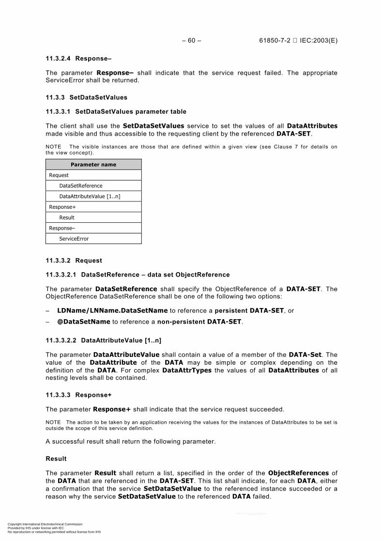
– 60 – 61850-7-2 IEC:2003(E)
11.3.2.4 Response–
The parameter Response– shall indicate that the service request failed. The appropriateServiceError shall be returned.
11.3.3 SetDataSetValues
11.3.3.1 SetDataSetValues parameter table
The client shall use the SetDataSetValues service to set the values of all DataAttributesmade visible and thus accessible to the requesting client by the referenced DATA-SET.
NOTE The visible instances are those that are defined within a given view (see Clause 7 for details onthe view concept).
Parameter name
Request
DataSetReference
DataAttributeValue [1..n]
Response+
Result
Response–
ServiceError
11.3.3.2 Request
11.3.3.2.1 DataSetReference – data set ObjectReference
The parameter DataSetReference shall specify the ObjectReference of a DATA-SET. TheObjectReference DataSetReference shall be one of the following two options:
– LDName/LNName.DataSetName to reference a persistent DATA-SET, or
– @DataSetName to reference a non-persistent DATA-SET.
11.3.3.2.2 DataAttributeValue [1..n]
The parameter DataAttributeValue shall contain a value of a member of the DATA-Set. Thevalue of the DataAttribute of the DATA may be simple or complex depending on thedefinition of the DATA. For complex DataAttrTypes the values of all DataAttributes of allnesting levels shall be contained.
11.3.3.3 Response+
The parameter Response+ shall indicate that the service request succeeded.
NOTE The action to be taken by an application receiving the values for the instances of DataAttributes to be set isoutside the scope of this service definition.
A successful result shall return the following parameter.
Result
The parameter Result shall return a list, specified in the order of the ObjectReferences ofthe DATA that are referenced in the DATA-SET. This list shall indicate, for each DATA, eithera confirmation that the service SetDataSetValue to the referenced instance succeeded or areason why the service SetDataSetValue to the referenced DATA failed.
Copyright International Electrotechnical Commission Provided by IHS under license with IEC
Not for ResaleNo reproduction or networking permitted without license from IHS
--``````-`-`,,`,,`,`,,`---

61850-7-2 © IEC:2003(E) – 61 –
11.3.3.4 Response–
The parameter Response– shall indicate that the service request failed. The appropriateServiceError shall be returned.
11.3.4 CreateDataSet
11.3.4.1 CreateDataSet parameter table
The client shall use the CreateDataSet service to request the server to create a DATA-SETwith a list of members defined with the functionally constrained data (FCD) or functionallyconstrained data attribute (FCDA) made visible and thus accessible to the requesting client.
NOTE The visible instances are those that are defined within a given view (see Clause 7 for details onthe view concept).
Parameter name
Request
DataSetReference
DSMemberRef [1..n]
Response+
Response–
ServiceError
11.3.4.2 Request
11.3.4.2.1 DataSetReference – data set ObjectReference
The parameter DataSetReference shall specify the ObjectReference of DATA-SET that is tobe created. The ObjectReference DataSetReference shall be one of the following two options:
– LDName/LNName.DataSetName to create a persistent DATA-SET, or
– @DataSetName to create a non-persistent DATA-SET.
11.3.4.2.2 DSMemberRef [1..n] – data set member ObjectReference
The parameter DSMemberRef shall specify the functionally constrained data (FCD) orfunctionally constrained data attribute (FCDA) of a DATA.
11.3.4.3 Response+
The parameter Response+ shall indicate that the service request succeeded. If one of thereferenced functionally constrained data (FCD) are not available to that client then the serviceshall fail.
11.3.4.4 Response–
The parameter Response– shall indicate that the service request failed. The appropriateServiceError shall be returned.
11.3.5 DeleteDataSet
11.3.5.1 DeleteDataSet parameter table
The client shall use the DeleteDataSet service to request the server to delete a DATA-SETmade visible and thus accessible to the requesting client.
Copyright International Electrotechnical Commission Provided by IHS under license with IEC
Not for ResaleNo reproduction or networking permitted without license from IHS
--``````-`-`,,`,,`,`,,`---
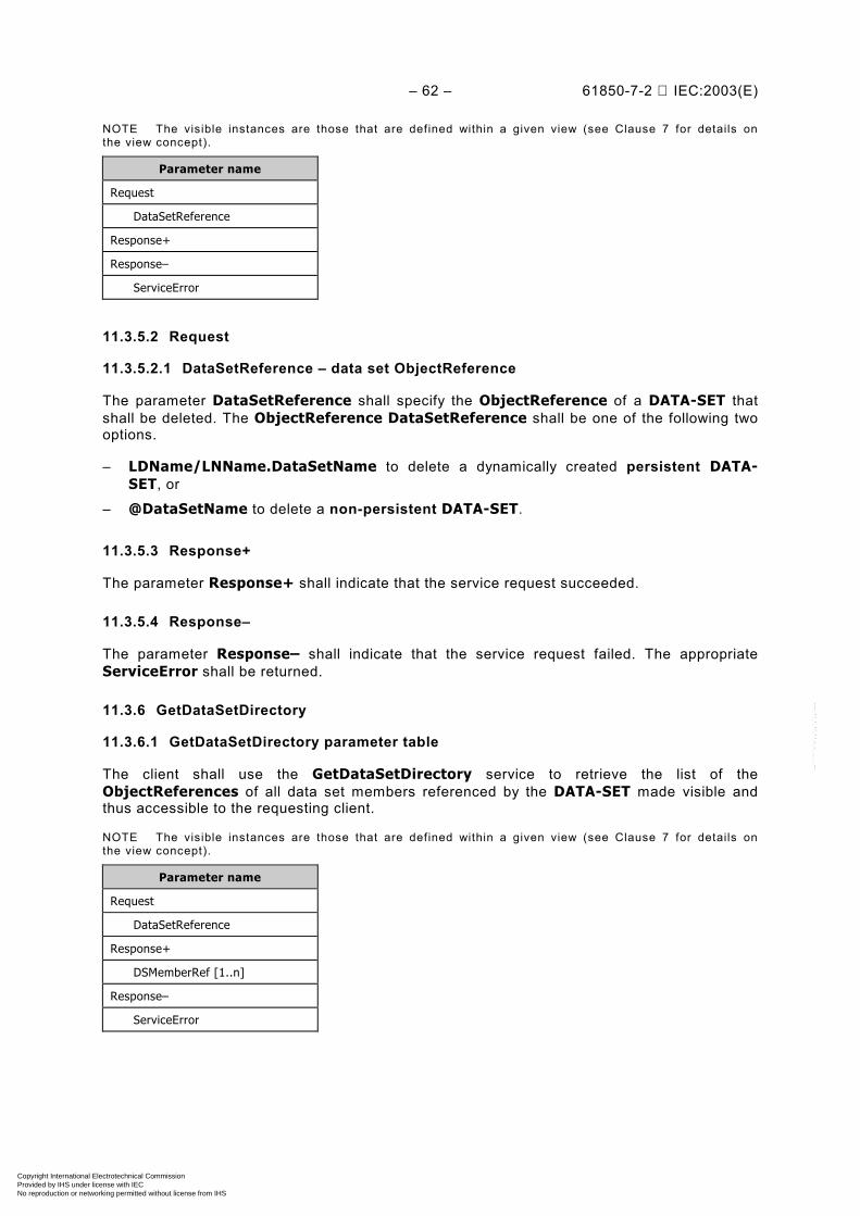
– 62 – 61850-7-2 IEC:2003(E)
NOTE The visible instances are those that are defined within a given view (see Clause 7 for details onthe view concept).
Parameter name
Request
DataSetReference
Response+
Response–
ServiceError
11.3.5.2 Request
11.3.5.2.1 DataSetReference – data set ObjectReference
The parameter DataSetReference shall specify the ObjectReference of a DATA-SET thatshall be deleted. The ObjectReference DataSetReference shall be one of the following twooptions.
– LDName/LNName.DataSetName to delete a dynamically created persistent DATA-SET, or
– @DataSetName to delete a non-persistent DATA-SET.
11.3.5.3 Response+
The parameter Response+ shall indicate that the service request succeeded.
11.3.5.4 Response–
The parameter Response– shall indicate that the service request failed. The appropriateServiceError shall be returned.
11.3.6 GetDataSetDirectory
11.3.6.1 GetDataSetDirectory parameter table
The client shall use the GetDataSetDirectory service to retrieve the list of theObjectReferences of all data set members referenced by the DATA-SET made visible andthus accessible to the requesting client.
NOTE The visible instances are those that are defined within a given view (see Clause 7 for details onthe view concept).
Parameter name
Request
DataSetReference
Response+
DSMemberRef [1..n]
Response–
ServiceError
Copyright International Electrotechnical Commission Provided by IHS under license with IEC
Not for ResaleNo reproduction or networking permitted without license from IHS
--``````-`-`,,`,,`,`,,`---
61850-7-2 © IEC:2003(E) – 63 –
11.3.6.2 Request
DataSetReference – data set ObjectReference
The parameter DataSetReference shall specify the ObjectReference of the DATA-SET. TheObjectReference DataSetReference shall be one of the following two options:
– LDName/LNName.DataSetName to reference a persistent DATA-SET, or
– @DataSetName to reference a non-persistent DATA-SET.
11.3.6.3 Response+
The parameter Response+ shall indicate that the service request succeeded. A successfulresult shall return the following parameter.
DSMemberRef [1..n] – data set member ObjectReference
The parameter DSMemberRef shall contain the ObjectReferences of the members of theDATA-SET.
NOTE The syntax of the DSMemberRef is defined in an SCSM.
11.3.6.4 Response–
The parameter Response– shall indicate that the service request failed. The appropriateServiceError shall be returned.
12 Substitution model
The substitution model provides the substitution of values of DataAttributes whose functionalconstraint equals MX (for analogue values) or ST (for status values). Basically, substitutionapplies to DataAttributes with FC (= MX and ST) and to the associated quality attribute.When substitution is enabled for a specific DataAttribute, the DATA shall provide thesubstituted values instead of the process value to the clients.
NOTE 1 Substituting values is part of the normal operation of a substation and has nothing to do with system ordevice tests. Tests are performed by setting a logical device into the test mode or setting the service parameter(=Test) of the control services to TRUE.
In the typical use case for substitution, an operator on the client side enters manually a valuefor a DataAttribute located in a specific device. The client sets the DataAttribute to thevalue entered. If a client accesses the value of that DataAttribute (for example, using aGetdataValue service or subscribing to a report) the client shall receive the manual entered(substituted) value instead of the value determined by the process.
The substitution model relies on four specific DataAttributes defined in IEC 61850-7-3.
– subEna (enable substitution): The current process value shall be replaced by the valueprovided in the DataAttribute subVal.
– subVal, subMag, and subCMag (values for substitution of process values): The currentprocess value shall be replaced by the value provided by the DataAttribute subVal,subMag and subCMag respectively.
– subQ (value for substitution of quality): The current process value shall be replaced bythe value provided by the DataAttribute subQ.
– subID (value to indicate the initiator of the substitution).
The detailed specification of these DataAttributes (defined in IEC 61850-7-3) shall befollowed in conjunction with this clause.
Copyright International Electrotechnical Commission Provided by IHS under license with IEC
Not for ResaleNo reproduction or networking permitted without license from IHS
--``````-`-`,,`,,`,`,,`---
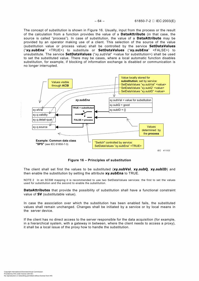
– 64 – 61850-7-2 IEC:2003(E)
The concept of substitution is shown in Figure 16. Usually, input from the process or the resultof the calculation from a function provides the value of a DataAttribute (in that case, thesource is called “process”). In case of substitution, the value of a DataAttribute may beprovided by an operator making use of a client. This selection of the source of the value(substitution value or process value) shall be controlled by the service SetDataValues(“xy.subEna” <TRUE>) to substitute or SetDataValues (“xy.subEna” <FALSE>) tounsubstitute. The service SetDataValues (“xy.subVal” <value for substitution>) shall be usedto set the substituted value. There may be cases, where a local automatic function disablessubstitution, for example, if blocking of information exchange is disabled or communication isno longer interrupted.
xy.stVal
Example: Common data class"SPS" (see IEC 61850-7-3)
xy.q.validity
xy.q.detail-qual
xy.q.source
TRUE = substituted
FALSE = process
xy.subVal = value for substitutionxy.subQ = goodxy.subID = {}
xy.subEna
Values visiblethrough ACSI
”Switch" controlled by service:SetDataValues ”xy.subEna” <TRUE>
Value locally stored forsubstitution; set by service:SetDataValues ”xy.subVal” <value>SetDataValues ”xy.subQ” <value>SetDataValues ”xy.subID” <value>
Valuesdetermined bythe process
Figure 16 – Principles of substitution
The client shall set first the values to be substituted (xy.subVal, xy.subQ, xy.subID) andthen enable the substitution by setting the attribute xy.subEna to TRUE.
NOTE 2 In an SCSM mapping it is recommended to use two SetDataValues services: the first to set the valuesused for substitution and the second to enable the substitution.
DataAttributes that provide the possibility of substitution shall have a functional constraintvalue of SV (substitutable value).
In case the association over which the substitution has been enabled fails, the substitutedvalues shall remain unchanged. Changes shall be initiated by a service or by local means inthe server device.
If the client has no direct access to the server responsible for the data acquisition (for example,in a hierarchical system, with a gateway in between, where the client needs to access a proxy),it shall be a local issue of the proxy how to handle the substitution.
IEC 411/03
Copyright International Electrotechnical Commission Provided by IHS under license with IEC
Not for ResaleNo reproduction or networking permitted without license from IHS
--``````-`-`,,`,,`,`,,`---

61850-7-2 © IEC:2003(E) – 65 –
13 SETTING-GROUP-CONTROL-BLOCK class model
13.1 General
An instance of a DATA usually has one value. The SETTING-GROUP-CONTROL-BLOCK(SGCB) model allows for an instance to have several values that can be used one at a time.The SGCB provides mechanisms to switch between several values of one or more DATA.Values that belong together build the setting group (SG).
NOTE A logical node zero (LLN0) may have one SETTING-GROUP-CONTROL-BLOCK. Many setting DATA aredefined in IEC 61850-7-4.
The SGCB model provides services to handle different values for one or more DATA. The SGwhose values are currently used by the DATA of a LOGICAL-NODE shall be in the state“active”. The SG that can be edited shall be in the state “edit”.
The SGCB model is depicted in the example in Figure 17. The LOGICAL-NODE “PVOC”(voltage controlled/dependent time overcurrent according to IEC 61850-7-4) comprises eightDATA for settings (LN PDIF has one DATA for settings) – (MinOpTmms, ..., RstrMode). TheSGCB “SG Control” provides three SGs (#1, #2, and #3) each with independent values for thenine DATA. Each SG contains nine values (one for each of: MinOpTmms, ..., RstrMode). Themembers of the active SG are referenced by the ObjectReferences of the DATA withfunctional constraint SG. The members of the SG in the “edit buffer” are referenced by theObjectReferences of the DATA with functional constraint SE.
Minimum Operate TimeOperating Curve Type (volt.)Operating Curve Type (amp)Time MultiplierReset Curve TypeMaximum Operate TimeOperate Delay TimeReset Delay Time
LN PVOC
SettingsMinOpTmmsAVCrvTmACrvTmMultTypRsCrvMaxOpTmmsOpDlTmmsRsDlTmms
1223
124355646534543
LN PDIF
Restraint Mode RstMod 9
SG Control Block
Settings
Status information... Setting
data
Active buffer
Min
OpT
mm
s
AVC
rv
TmA
Crv
TmM
ult
TypR
sCrv
Min
OpT
mm
s
OpD
lTm
ms
RsD
lTm
ms
Rst
Mod
Logical node
Activesettinggroup= #1
Sele
ctAc
tiveS
G
SetS
GV
alue
s
Get
SGVa
lues
#1
#2
#3
Totalnumber ofSG = 3
Get
SGC
BVal
ues
Settinggroup #3can beedited
DataName
Sele
ctE
ditS
G #
3
#1
#2
#3
SG
122 3 12 435 564 653 45 43 9
21 13 211 243 828 42 43 5 8
222 111 121 543 243 23 43 4 4
Data value
Get
SGVa
lues
222 111 121 543 243 23 43 4 4
Edit buffer
Con
firm
Edi
tSG
Valu
es
#3SelectEditSG #3 ConfirmEditSGValues
Figure 17 – Basic model of the settings model
IEC 412/03
Copyright International Electrotechnical Commission Provided by IHS under license with IEC
Not for ResaleNo reproduction or networking permitted without license from IHS
--``````-`-`,,`,,`,`,,`---
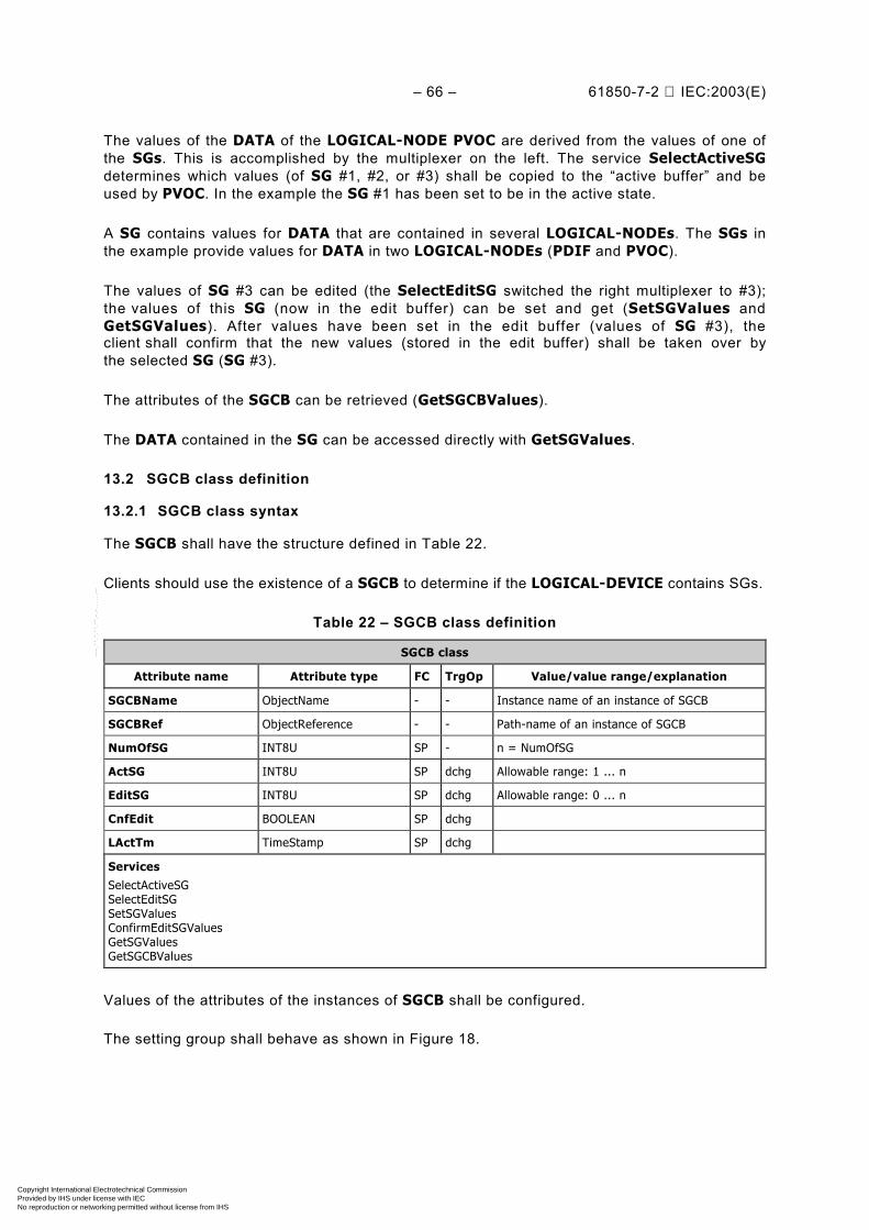
– 66 – 61850-7-2 IEC:2003(E)
The values of the DATA of the LOGICAL-NODE PVOC are derived from the values of one ofthe SGs. This is accomplished by the multiplexer on the left. The service SelectActiveSGdetermines which values (of SG #1, #2, or #3) shall be copied to the “active buffer” and beused by PVOC. In the example the SG #1 has been set to be in the active state.
A SG contains values for DATA that are contained in several LOGICAL-NODEs. The SGs inthe example provide values for DATA in two LOGICAL-NODEs (PDIF and PVOC).
The values of SG #3 can be edited (the SelectEditSG switched the right multiplexer to #3);the values of this SG (now in the edit buffer) can be set and get (SetSGValues andGetSGValues). After values have been set in the edit buffer (values of SG #3), theclient shall confirm that the new values (stored in the edit buffer) shall be taken over bythe selected SG (SG #3).
The attributes of the SGCB can be retrieved (GetSGCBValues).
The DATA contained in the SG can be accessed directly with GetSGValues.
13.2 SGCB class definition
13.2.1 SGCB class syntax
The SGCB shall have the structure defined in Table 22.
Clients should use the existence of a SGCB to determine if the LOGICAL-DEVICE contains SGs.
Table 22 – SGCB class definition
SGCB class
Attribute name Attribute type FC TrgOp Value/value range/explanation
SGCBName ObjectName - - Instance name of an instance of SGCB
SGCBRef ObjectReference - - Path-name of an instance of SGCB
NumOfSG INT8U SP - n = NumOfSG
ActSG INT8U SP dchg Allowable range: 1 ... n
EditSG INT8U SP dchg Allowable range: 0 ... n
CnfEdit BOOLEAN SP dchg
LActTm TimeStamp SP dchg
ServicesSelectActiveSGSelectEditSGSetSGValuesConfirmEditSGValuesGetSGValuesGetSGCBValues
Values of the attributes of the instances of SGCB shall be configured.
The setting group shall behave as shown in Figure 18.
Copyright International Electrotechnical Commission Provided by IHS under license with IEC
Not for ResaleNo reproduction or networking permitted without license from IHS
--``````-`-`,,`,,`,`,,`---

61850-7-2 © IEC:2003(E) – 67 –
SG existsand hasvalues
Initial values configured
SG existsand can be
edited
GetSGValues [FC=SG]
SG existsand is active
SelectActiveSG(copy valuesto active buffer)
SelectActiveSGof another SG
SetSGValues [FC=SE]GetSGValues [FC=SE]
SelectEditSG(copy values to edit buffer)
ConfirmEditSGValues
Figure 18 – Setting group state machine
The state changes shall be issued as defined with the corresponding attributes of the SGCBand the corresponding services of the SGCB.
13.2.2 SGCB class attributes
13.2.2.1 SGCBName – setting group control name
The attribute SGCBName shall be SGCB within the scope of a LLN0.
13.2.2.2 SGCBRef – setting group control ObjectReference
The attribute SGCBRef shall be the unique path-name of an SGCB.
The ObjectReference SGCBRef shall be:
LDName/LLN0.SGCB
NOTE SGCB is the standardized instance name of the SGCB.
13.2.2.3 NumOfSG – number of setting groups
The attribute NumOfSG shall identify the total number of SGs that are available in aLOGICAL-DEVICE.
If there are any DataAttributes with functional constraint SG in a LOGICAL-DEVICE then asingle SGCB shall be present in the LOGICAL-DEVICE.
The attribute NumOfSG shall not be settable. The value of NumOfSG is a local matter.
IEC 413/03
Copyright International Electrotechnical Commission Provided by IHS under license with IEC
Not for ResaleNo reproduction or networking permitted without license from IHS
--``````-`-`,,`,,`,`,,`---
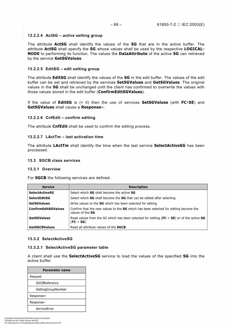
– 68 – 61850-7-2 IEC:2003(E)
13.2.2.4 ActSG – active setting group
The attribute ActSG shall identify the values of the SG that are in the active buffer. Theattribute ActSG shall specify the SG whose values shall be used by the respective LOGICAL-NODE to performing its function. The values the DataAttribute of the active SG can retrievedby the service GetSGValues.
13.2.2.5 EditSG – edit setting group
The attribute EditSG shall identify the values of the SG in the edit buffer. The values of the editbuffer can be set and retrieved by the services SetSGValues and GetSGValues. The originalvalues in the SG shall be unchanged until the client has confirmed to overwrite the values withthose values stored in the edit buffer (ConfirmEditSGValues).
If the value of EditSG is (= 0) then the use of services SetSGValues (with FC=SE) andGetSGValues shall cause a Response–.
13.2.2.6 CnfEdit – confirm editing
The attribute CnfEdit shall be used to confirm the editing process.
13.2.2.7 LActTm – last activation time
The attribute LActTm shall identify the time when the last service SelectActiveSG has beenprocessed.
13.3 SGCB class services
13.3.1 Overview
For SGCB the following services are defined.
Service Description
SelectActiveSG Select which SG shall become the active SG
SelectEditSG Select which SG shall become the SG that can be edited after selecting
SetSGValues Write values to the SG which has been selected for editing
ConfirmEditSGValues Confirm that the new values to the SG which has been selected for editing become thevalues of the SG
GetSGValues Read values from the SG which has been selected for editing (FC = SE) or of the active SG(FC = SG)
GetSGCBValues Read all attribute values of the SGCB
13.3.2 SelectActiveSG
13.3.2.1 SelectActiveSG parameter table
A client shall use the SelectActiveSG service to load the values of the specified SG into theactive buffer.
Parameter name
Request
SGCBReference
SettingGroupNumber
Response+
Response–
ServiceError
Copyright International Electrotechnical Commission Provided by IHS under license with IEC
Not for ResaleNo reproduction or networking permitted without license from IHS
--``````-`-`,,`,,`,`,,`---
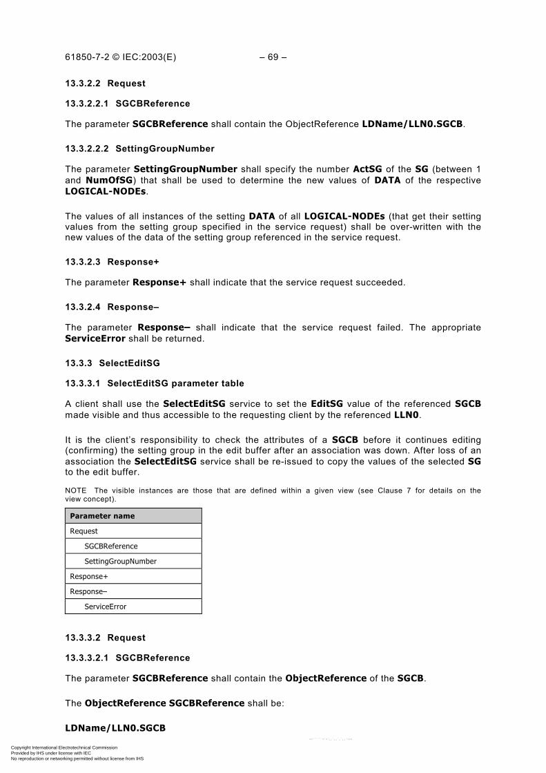
61850-7-2 © IEC:2003(E) – 69 –
13.3.2.2 Request
13.3.2.2.1 SGCBReference
The parameter SGCBReference shall contain the ObjectReference LDName/LLN0.SGCB.
13.3.2.2.2 SettingGroupNumber
The parameter SettingGroupNumber shall specify the number ActSG of the SG (between 1and NumOfSG) that shall be used to determine the new values of DATA of the respectiveLOGICAL-NODEs.
The values of all instances of the setting DATA of all LOGICAL-NODEs (that get their settingvalues from the setting group specified in the service request) shall be over-written with thenew values of the data of the setting group referenced in the service request.
13.3.2.3 Response+
The parameter Response+ shall indicate that the service request succeeded.
13.3.2.4 Response–
The parameter Response– shall indicate that the service request failed. The appropriateServiceError shall be returned.
13.3.3 SelectEditSG
13.3.3.1 SelectEditSG parameter table
A client shall use the SelectEditSG service to set the EditSG value of the referenced SGCBmade visible and thus accessible to the requesting client by the referenced LLN0.
It is the client’s responsibility to check the attributes of a SGCB before it continues editing(confirming) the setting group in the edit buffer after an association was down. After loss of anassociation the SelectEditSG service shall be re-issued to copy the values of the selected SGto the edit buffer.
NOTE The visible instances are those that are defined within a given view (see Clause 7 for details on theview concept).
Parameter name
Request
SGCBReference
SettingGroupNumber
Response+
Response–
ServiceError
13.3.3.2 Request
13.3.3.2.1 SGCBReference
The parameter SGCBReference shall contain the ObjectReference of the SGCB.
The ObjectReference SGCBReference shall be:
LDName/LLN0.SGCB
Copyright International Electrotechnical Commission Provided by IHS under license with IEC
Not for ResaleNo reproduction or networking permitted without license from IHS
--``````-`-`,,`,,`,`,,`---

– 70 – 61850-7-2 IEC:2003(E)
13.3.3.2.2 SettingGroupNumber
The parameter SettingGroupNumber shall specify the number EditSG of the SG (between 1and NumOfSG) that shall be used to set values (SetSGValues), confirm values(ConfirmEditSGValues), and retrieve values (GetSGValues) of the specified SG.
13.3.3.3 Response+
The parameter Response+ shall indicate that the service request succeeded.
13.3.3.4 Response–
The parameter Response– shall indicate that the service request failed. The appropriateServiceError shall be returned.
13.3.4 SetSGValues
13.3.4.1 SetSGValues parameter table
A client shall use the SetSGValues service to set the value of the DATA of the SG identified bythe value of the attribute EditSG of the SGCB made visible and thus accessible to therequesting client by the referenced LLN0.
Setting new values shall become effective only after the client has confirmed the values byissuing the service ConfirmEditSGValues.
NOTE The visible instances are those that are defined within a given view (see Clause 7 for details onthe view concept).
Parameter name
Request
Reference
DataAttributeValue [1..n]
Response+
Response–
ServiceError
13.3.4.2 Request
13.3.4.2.1 Reference
The parameter Reference shall specify the functionally constrained data (FCD) orfunctionally constrained data attributes (FCDA) of the DATA whose DataAttributevalues are to be written. The Reference shall be FCD or FCDA.
The FunctionalConstraint value of the FCD or FCDA shall be SE.
13.3.4.2.2 DataAttributeValue [1..n]
The parameter DataAttributeValue shall contain
– the values of all DataAttributes of a DATA referenced by FCD; or
– the value of a DataAttribute referenced by FCDA
of the SG identified by the value of the attribute EditSG of the SGCB.
NOTE The syntax of the DataAtributeValue is defined in an SCSM.
Copyright International Electrotechnical Commission Provided by IHS under license with IEC
Not for ResaleNo reproduction or networking permitted without license from IHS
--``````-`-`,,`,,`,`,,`---
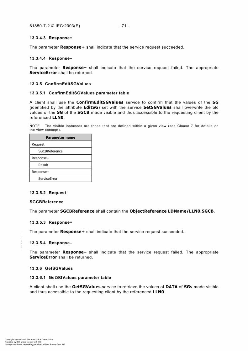
61850-7-2 © IEC:2003(E) – 71 –
13.3.4.3 Response+
The parameter Response+ shall indicate that the service request succeeded.
13.3.4.4 Response–
The parameter Response– shall indicate that the service request failed. The appropriateServiceError shall be returned.
13.3.5 ConfirmEditSGValues
13.3.5.1 ConfirmEditSGValues parameter table
A client shall use the ConfirmEditSGValues service to confirm that the values of the SG(identified by the attribute EditSG) set with the service SetSGValues shall overwrite the oldvalues of the SG of the SGCB made visible and thus accessible to the requesting client by thereferenced LLN0.
NOTE The visible instances are those that are defined within a given view (see Clause 7 for details onthe view concept).
Parameter name
Request
SGCBReference
Response+
Result
Response–
ServiceError
13.3.5.2 Request
SGCBReference
The parameter SGCBReference shall contain the ObjectReference LDName/LLN0.SGCB.
13.3.5.3 Response+
The parameter Response+ shall indicate that the service request succeeded.
13.3.5.4 Response–
The parameter Response– shall indicate that the service request failed. The appropriateServiceError shall be returned.
13.3.6 GetSGValues
13.3.6.1 GetSGValues parameter table
A client shall use the GetSGValues service to retrieve the values of DATA of SGs made visibleand thus accessible to the requesting client by the referenced LLN0.
Copyright International Electrotechnical Commission Provided by IHS under license with IEC
Not for ResaleNo reproduction or networking permitted without license from IHS
--``````-`-`,,`,,`,`,,`---
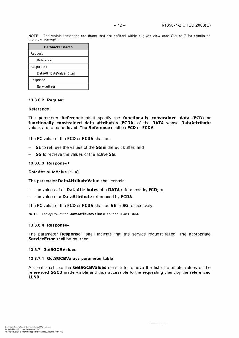
– 72 – 61850-7-2 IEC:2003(E)
NOTE The visible instances are those that are defined within a given view (see Clause 7 for details onthe view concept).
Parameter name
Request
Reference
Response+
DataAttributeValue [1..n]
Response–
ServiceError
13.3.6.2 Request
Reference
The parameter Reference shall specify the functionally constrained data (FCD) orfunctionally constrained data attributes (FCDA) of the DATA whose DataAttributevalues are to be retrieved. The Reference shall be FCD or FCDA.
The FC value of the FCD or FCDA shall be
– SE to retrieve the values of the SG in the edit buffer; and
– SG to retrieve the values of the active SG.
13.3.6.3 Response+
DataAttributeValue [1..n]
The parameter DataAttributeValue shall contain
– the values of all DataAttributes of a DATA referenced by FCD; or
– the value of a DataAttribute referenced by FCDA.
The FC value of the FCD or FCDA shall be SE or SG respectively.
NOTE The syntax of the DataAtributeValue is defined in an SCSM.
13.3.6.4 Response–
The parameter Response– shall indicate that the service request failed. The appropriateServiceError shall be returned.
13.3.7 GetSGCBValues
13.3.7.1 GetSGCBValues parameter table
A client shall use the GetSGCBValues service to retrieve the list of attribute values of thereferenced SGCB made visible and thus accessible to the requesting client by the referencedLLN0.
Copyright International Electrotechnical Commission Provided by IHS under license with IEC
Not for ResaleNo reproduction or networking permitted without license from IHS
--``````-`-`,,`,,`,`,,`---

61850-7-2 © IEC:2003(E) – 73 –
NOTE The visible instances are those that are defined within a given view (see Clause 7 for details onthe view concept).
Parameter name
Request
SGCBReference
FunctionalConstraint
Response+
NumberOfSettingGroup
ActiveSettingGroup
EditSettingGroup
LastActivateTime
Response–
ServiceError
13.3.7.2 Request
13.3.7.2.1 SGCBReference
The parameter SGCBReference shall contain the ObjectReference LDName/LLN0.SGCB.
13.3.7.2.2 FunctionalConstraint
The parameter FunctionalConstraint shall contain the value of the functional constraintparameter to identify the functional constraint of the respective attribute of SGCB contained inthe LLN0. The value shall be SP.
13.3.7.3 Response+
13.3.7.3.1 NumberOfSettingGroup – number of setting group controls
The parameter NumberOfSettingGroup shall specify the total number of the SG of theattribute NumOfSG of the referenced SGCB.
13.3.7.3.2 ActiveSettingGroup – active setting group
The parameter ActiveSettingGroup shall specify the number of the SGs of the attributeActiveSG from which the current active SG values shall be derived.
13.3.7.3.3 EditSettingGroup – edit setting group
The parameter EditSettingGroup shall specify the number of the SG of the attribute EditSGwhose values can be set and retrieved.
13.3.7.3.4 LastActivateTime – last time of activation of a setting group
The parameter LastActivateTime shall specify the time of the last activation of the attributeLActTm.
13.3.7.4 Response–
The Response– parameter shall indicate that the service request failed. The appropriateServiceError shall be returned.
Copyright International Electrotechnical Commission Provided by IHS under license with IEC
Not for ResaleNo reproduction or networking permitted without license from IHS
--``````-`-`,,`,,`,`,,`---
– 74 – 61850-7-2 IEC:2003(E)
14 REPORT-CONTROL-BLOCK and LOG-CONTROL-BLOCK class models
14.1 Overview
Reporting and logging meets a number of crucial requirements for event-driven informationexchange. The data transfer models described in this clause provide mechanisms fortransferring data values caused by well-defined conditions from a logical node to one client orstoring the data in a server's log for future querying.
In contrast to high bandwidth and time-consuming fast reading (polling) devices forextraordinary event occurrences, the reporting provides immediate transmission of events.Reporting is controlled by constraints.
The main characteristics of reporting and logging are:
– timely reports serve as an indication to clients under real-time constraints (optionallykeeping sequence-of-events to the client),
– logging of events for later retrieval (sequence-of-events stored in server),– the impact on network bandwidth is minimized,– sending reports only when required (controlled by several attributes),– low-frequency integrity scan and client-initiated general interrogation.
Reporting provides mechanisms to report packed values of instances of DATA immediately orafter some buffer time. The logging model provides mechanisms to store events in the log insequence. A client may query a range of log entries at any time.
Reporting and logging as well as the basic services of the data model provide flexible dataretrieval schemas, for example:
– change-of-state notification of clients: immediate reports,– sequence-of-events: keeping reports in sequence or storing and querying sequences of log
entries,– polling data at any time: GetDataValues and GetDataSetValues
NOTE 1 Subclause 14.3.5.3.4 provides special services for event distribution (generic substation event model,GSE). Reporting and GSE have totally different qualities of services and behaviour. Reporting is connection-oriented(GSE uses multicast), reporting transmits data once (GSE transmits and retransmits data with heartbeat).IEC 61850-7-1 provides a comparison of the models.
NOTE 2 Clause 16 specifies special services for communication of measured values of, for example, voltagetransformer (VT) and current transformer (CT) under crucial time constraints.
The principle building blocks and services for reporting and logging are depicted in Figure 19.
Copyright International Electrotechnical Commission Provided by IHS under license with IEC
Not for ResaleNo reproduction or networking permitted without license from IHS
--``````-`-`,,`,,`,`,,`---
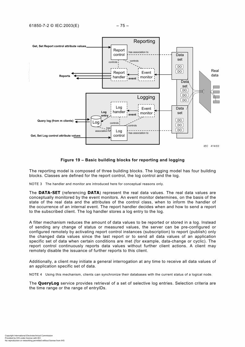
61850-7-2 © IEC:2003(E) – 75 –
Dataset
Reportcontrol
Reporthandler
Eventmonitor
Dataset
has association to
controls controls
eventReports
Get, Set Report control attribute valuesReporting
Logging
LogcontrolGet, Set Log control attribute values
Loghandler
Eventmonitorevent
controlscontrols
has association to
Log
Logentry
Query log (from m clients)
Realdata
hasassociation to
Dataset
DO
DO
DO
DO
DO
DO
DO
DO
Figure 19 – Basic building blocks for reporting and logging
The reporting model is composed of three building blocks. The logging model has four buildingblocks. Classes are defined for the report control, the log control and the log.
NOTE 3 The handler and monitor are introduced here for conceptual reasons only.
The DATA-SET (referencing DATA) represent the real data values. The real data values areconceptually monitored by the event monitors. An event monitor determines, on the basis of thestate of the real data and the attributes of the control class, when to inform the handler ofthe occurrence of an internal event. The report handler decides when and how to send a reportto the subscribed client. The log handler stores a log entry to the log.
A filter mechanism reduces the amount of data values to be reported or stored in a log. Insteadof sending any change of status or measured values, the server can be pre-configured orconfigured remotely by activating report control instances (subscription) to report (publish) onlythe changed data values since the last report or to send all data values of an applicationspecific set of data when certain conditions are met (for example, data-change or cyclic). Thereport control continuously reports data values without further client actions. A client mayremotely disable the issuance of further reports to this client.
Additionally, a client may initiate a general interrogation at any time to receive all data values ofan application specific set of data.
NOTE 4 Using this mechanism, clients can synchronize their databases with the current status of a logical node.
The QueryLog service provides retrieval of a set of selective log entries. Selection criteria arethe time range or the range of entryIDs.
IEC 414/03
Copyright International Electrotechnical Commission Provided by IHS under license with IEC
Not for ResaleNo reproduction or networking permitted without license from IHS
--``````-`-`,,`,,`,`,,`---

– 76 – 61850-7-2 IEC:2003(E)
14.2 REPORT-CONTROL-BLOCK class model
14.2.1 Basic concepts
The REPORT-CONTROL-BLOCK shall control the procedures that are required for reportingvalues of DATA from one or more LOGICAL-NODEs to one client. Instances of report controlshall be configured in the server at configuration time.
A server shall restrict access to an instance of a report control to one client at a time. Thatclient exclusively shall “own” that instance and shall receive reports from that instance of reportcontrol.
There are two classes of report control defined, each with a slightly different behaviour.
– BUFFERED-REPORT-CONTROL-BLOCK (BRCB) – internal events (caused by triggeroptions data-change, quality-change, and data-update) issue immediate sending of reportsor buffer the events (to some practical limit) for transmission, such that values of DATA arenot lost due to transport flow control constraints or loss of connection. BRCB provides thesequence-of-events (SOE) functionality.
– UNBUFFERED-REPORT-CONTROL-BLOCK (URCB) – internal events (caused by triggeroptions data-change, quality-change, and data-update) issue immediate sending of reportson a “best efforts” basis. If no association exists, or if the transport data flow is not fastenough to support it, events may be lost.
To allow multiple clients to receive the same values of DATA, multiple instances of the reportcontrol classes shall be made available.
For the unbuffered report control, this is achieved as follows.
a) A server shall make multiple instances of a report control class available with all instancesvisible to all clients. Each instance name shall be distinct by appending a technologicalindex (1..n). Clients may be configured to directly use a specific instance, or may browsethe instances for one that is currently disabled and hence available. When anUNBUFFERED-REPORT-CONTROL-BLOCK is reserved by a client, all other clients shallhave no set access to its parameters.
b) A server shall permit a client to view only one instance of the report control class based oneither the client’s connection or on its authentication’s view of the IED’s data model. Theinstance name shall be the same for each client and the server shall manage theseparation of the instances. The number of concurrent clients that can use these instancesmay be limited by the resources of the server.
The above two approaches are equivalent from the point of view of a client wishing to usereporting services: the client uses the first report control which it can enable.
For the buffered report controls, this is achieved as follows.
The buffered report controls shall be configured. These report controls are usually intendedto be used by a client implementing a well-defined functionality, for example, a SCADA master.The client may know the ObjectReference of the BRCB by configuration or by the use of anaming convention. The visibility of these instances may be a subject of access control. Whena BRCB is enabled, all other clients have no access right to set its parameters. A BRCB shallbe disabled by explicit request by the client.
14.2.2 BUFFERED-REPORT-CONTROL-BLOCK (BRCB) class definition
14.2.2.1 BRCB class Syntax
The BRCB class shall have the structure defined in Table 23.
Copyright International Electrotechnical Commission Provided by IHS under license with IEC
Not for ResaleNo reproduction or networking permitted without license from IHS
--``````-`-`,,`,,`,`,,`---
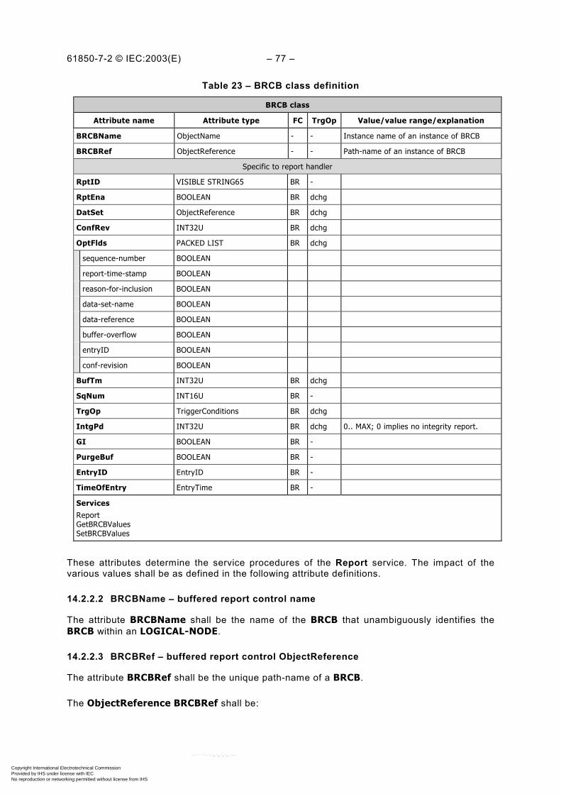
61850-7-2 © IEC:2003(E) – 77 –
Table 23 – BRCB class definition
BRCB class
Attribute name Attribute type FC TrgOp Value/value range/explanation
BRCBName ObjectName - - Instance name of an instance of BRCB
BRCBRef ObjectReference - - Path-name of an instance of BRCB
Specific to report handler
RptID VISIBLE STRING65 BR -
RptEna BOOLEAN BR dchg
DatSet ObjectReference BR dchg
ConfRev INT32U BR dchg
OptFlds PACKED LIST BR dchg
sequence-number BOOLEAN
report-time-stamp BOOLEAN
reason-for-inclusion BOOLEAN
data-set-name BOOLEAN
data-reference BOOLEAN
buffer-overflow BOOLEAN
entryID BOOLEAN
conf-revision BOOLEAN
BufTm INT32U BR dchg
SqNum INT16U BR -
TrgOp TriggerConditions BR dchg
IntgPd INT32U BR dchg 0.. MAX; 0 implies no integrity report.
GI BOOLEAN BR -
PurgeBuf BOOLEAN BR -
EntryID EntryID BR -
TimeOfEntry EntryTime BR -
ServicesReportGetBRCBValuesSetBRCBValues
These attributes determine the service procedures of the Report service. The impact of thevarious values shall be as defined in the following attribute definitions.
14.2.2.2 BRCBName – buffered report control name
The attribute BRCBName shall be the name of the BRCB that unambiguously identifies theBRCB within an LOGICAL-NODE.
14.2.2.3 BRCBRef – buffered report control ObjectReference
The attribute BRCBRef shall be the unique path-name of a BRCB.
The ObjectReference BRCBRef shall be:
Copyright International Electrotechnical Commission Provided by IHS under license with IEC
Not for ResaleNo reproduction or networking permitted without license from IHS
--``````-`-`,,`,,`,`,,`---
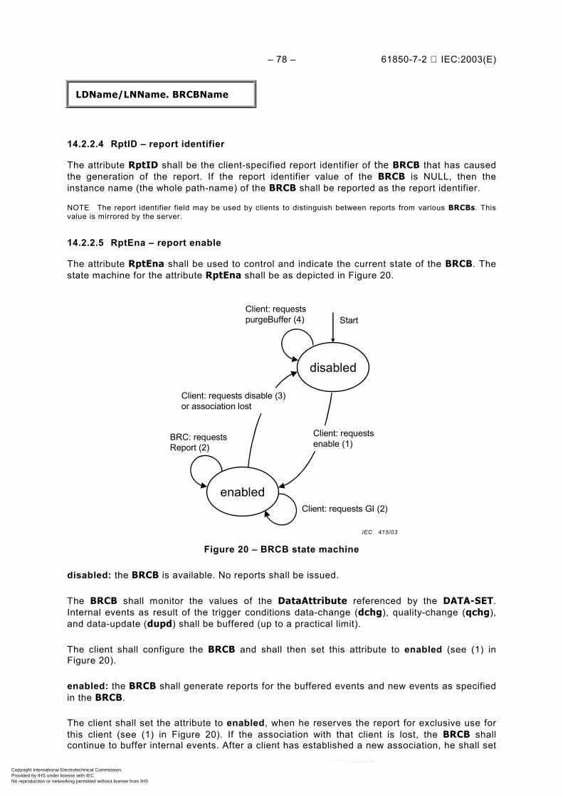
– 78 – 61850-7-2 IEC:2003(E)
LDName/LNName. BRCBName
14.2.2.4 RptID – report identifier
The attribute RptID shall be the client-specified report identifier of the BRCB that has causedthe generation of the report. If the report identifier value of the BRCB is NULL, then theinstance name (the whole path-name) of the BRCB shall be reported as the report identifier.
NOTE The report identifier field may be used by clients to distinguish between reports from various BRCBs. Thisvalue is mirrored by the server.
14.2.2.5 RptEna – report enable
The attribute RptEna shall be used to control and indicate the current state of the BRCB. Thestate machine for the attribute RptEna shall be as depicted in Figure 20.
disabled
Start
enabled
BRC: requests Report (2)
Client: requests disable (3)or association lost
Client: requests purgeBuffer (4)
Client: requests enable (1)
Client: requests GI (2)
Figure 20 – BRCB state machine
disabled: the BRCB is available. No reports shall be issued.
The BRCB shall monitor the values of the DataAttribute referenced by the DATA-SET.Internal events as result of the trigger conditions data-change (dchg), quality-change (qchg),and data-update (dupd) shall be buffered (up to a practical limit).
The client shall configure the BRCB and shall then set this attribute to enabled (see (1) inFigure 20).
enabled: the BRCB shall generate reports for the buffered events and new events as specifiedin the BRCB.
The client shall set the attribute to enabled, when he reserves the report for exclusive use forthis client (see (1) in Figure 20). If the association with that client is lost, the BRCB shallcontinue to buffer internal events. After a client has established a new association, he shall set
IEC 415/03
Copyright International Electrotechnical Commission Provided by IHS under license with IEC
Not for ResaleNo reproduction or networking permitted without license from IHS
--``````-`-`,,`,,`,`,,`---
61850-7-2 © IEC:2003(E) – 79 –
the attribute to enabled following that, the BRCB shall continue sending the reports stored inthe buffer over the association over which the attribute has been set to enabled.
NOTE The client who has enabled the BRCB receives the stored reports. A restricted view to the BRCB to oneclient guarantees that only the same client as before can receive the buffered reports.
To release the BRCB the client shall set this attribute to disabled.
While in the state enabled no changes of attribute values of the BRCB shall be allowed exceptdisabling and activating general-integration.
The attributes of a BRCB in state enabled shall be read only to the clients of all otherassociations.
14.2.2.6 DatSet – Data set reference
The attribute DatSet shall specify the ObjectReference of the DATA-SET being monitoredand whose values of the members of the DATA-SET (one, a subset, or all) shall be reported.
The DatSet shall be included in the report if data-set-name in OptFlds of the BRCB is set toTRUE otherwise it shall be omitted in the report.
A change of the value of the attribute DatSet shall have the same effect as setting purgeBufto TRUE.
14.2.2.7 ConfRev – configuration revision
The attribute ConfRev shall represent a count of the number of times that the configuration ofthe DATA-SET referenced by DatSet has been changed. Changes that shall be counted are:
– any deletion of a member of the DATA-SET; and
– the reordering of members of the DATA-SET.
The counter shall be incremented when the configuration changes.
The initial value for ConfRev is outside the scope of this part of IEC 61850. The value of 0shall be reserved. A restart of the IED shall not reset the value.
NOTE Configuration changes of DATA-SETs due to processing of services are not allowed (see DATA-SETmodel). Changes to be taken into account for the ConfRev are those made by local means like systemconfiguration.
14.2.2.8 OptFlds – optional fields to include in report
The attribute OptFlds shall be the client-specified optional fields to be included in the reportissued by this BRCB. This attribute defines a subset of the optional header fields of the report(see 14.2.3.2.2.1) that shall be included in the report:
– sequence-number (if TRUE SqNum shall be included in the report);
– report-time-stamp (if TRUE TimeOfEntry shall be included in the report);
– reason-for-inclusion (if TRUE ReasonCode shall be included in the report);
– data-set-name (if TRUE DatSet shall be included in the report);
– data-reference (if TRUE DataRef or DataAttributeReference shall be included in thereport);
– buffer-overflow (if TRUE BufOvfl shall be included in the report);
– entryID (if TRUE EntryID shall be included in the report);
Copyright International Electrotechnical Commission Provided by IHS under license with IEC
Not for ResaleNo reproduction or networking permitted without license from IHS
--``````-`-`,,`,,`,`,,`---

– 80 – 61850-7-2 IEC:2003(E)
– conf-revision (if TRUE ConfRev shall be included in the report).
If a BRCB does not support one of the above options, then an attempt to set the correspondingbit to TRUE shall cause a negative response of the SetBRCBValues service.
14.2.2.9 BufTm – buffer time
The attribute BufTm (see Figure 21) shall specify the time interval in milliseconds for thebuffering of internal notifications caused by data-change (dchg), quality-change (qchg), data-update (dupd) by the BRCB for inclusion into a single report.
even
tev
ent
even
t
repo
rt
repo
rt
time
even
t
bufTm bufTm
even
t
Figure 21 – Buffer time
Upon receipt of the first internal event notification of the referenced DATA-SET, the BRCBshall start a timer of the duration buffer time. When the timer expires, the BRCB shall combineall internal events that have been received during the time interval into a single report. Thenext internal event following the timer expiration shall signal the new start of that timer.The default value of 0 shall be reserved to indicate that the buffer time attribute is not to beused by the BRCB. Each internal event shall cause the BRCB to send a single report. Thevalue shall be settable in 1 ms increments and shall be able to convey up to 1 h of buffer time.
NOTE 1 The standard does not require a specific implementation of the monitoring function in a server. Themechanism of how to monitor the application data is outside the scope of this part of IEC 61850. An internal eventis understood as an abstract internal indication that, for example, a specific status value has been changed.
In the case where a second internal notification of the same member of a DATA-SET hasoccurred prior to the expiration of BufTm, the BRCB
– shall for status information behave as if BufTm has expired and immediately send thereport, restart the timer with value BufTm and process the second notification; or
– may for analogue information behave as if BufTm has expired and immediately transmitthe report for transmission, restart the timer with value BufTm and process the secondnotification; or
– may for analogue information substitute the current value in the pending report withthe new one.
NOTE 2 Changes of the same member are communicated in consecutive reports. No reports will be lost becausethe BRCB buffers them.
If a BRCB does not support buffer time then an attempt to set the BufTm attribute to a valuegreater than zero shall cause a negative response of the SetReportControlValues service.
14.2.2.10 SqNum – sequence number
The attribute SqNum shall specify the sequence number for each BRCB that has report enableset to TRUE. This number is to be incremented by the BRCB for each report generated andsent. The increment shall occur once the BRCB has formatted the report and queued the reportto the N-1 protocol layer. The first report following the setting of the report enable to TRUEshall contain sequence number 0.
IEC 416/03
Copyright International Electrotechnical Commission Provided by IHS under license with IEC
Not for ResaleNo reproduction or networking permitted without license from IHS
--``````-`-`,,`,,`,`,,`---

61850-7-2 © IEC:2003(E) – 81 –
14.2.2.11 TrgOp – trigger options
The attribute TrgOp shall specify the trigger conditions which shall be monitored by this BRCB.The following values are defined:
– data-change (dchg)
– quality-change (qchg)
– data-update (dupd)
– integrity
– general-interrogation
The trigger options dchg, qchg, and dupd refer to the attribute trigger option (TrgOp) of theDataAttribute of the common DATA classes in IEC 61850-7-3. The trigger options integrityand general-interrogation shall be trigger conditions defined by the attributes IntgPd and GIof the BRCB respectively.
Details related to the generation of a report based on the different trigger options shall be asspecified in 14.2.3.2.3.
If a BRCB does not support one or more of the trigger options, the attempt to set the TrgOpattribute to TRUE for one of these not supported values, shall cause a negative response ofthe SetReportControlValues service.
14.2.2.12 IntgPd – integrity period
If TrgOp is set to integrity, the attribute IntgPd shall indicate the period in milliseconds usedfor generating an integrity report. An integrity report shall report the values of all members ofthe related DATA-SET. BufTm shall have no effect when this change issues a report.
If a BRCB does not support integrity period then an attempt to set the IntgPd attribute to avalue greater than 0 shall cause a negative response of the SetReportControlValues service.
A value of 0 shall indicate that no integrity reports shall be issued.
NOTE An integrity scan may transmit the same values as a general interrogation. The integrity scan is issued bythe server. The general-interrogation is issued by the client.
14.2.2.13 GI – general-interrogation
The attribute GI shall indicate the request to start the general-interrogation process. Aftersetting to TRUE, the BRCB shall start the general-interrogation process. After initiation ofthe general interrogation, this attribute shall be automatically set to FALSE by the BRCB.
If a BRCB does not support general-interrogation then an attempt to set the GI attribute toTRUE shall cause a negative response of the SetReportControlValues service.
14.2.2.14 PurgeBuf – purge buffer
The attribute PurgeBuf shall indicate the request to discard buffered events. After setting toTRUE, the BRCB shall discard all buffered events that have not yet been sent to the client.After discarding the buffered events, this attribute shall be automatically set to FALSE bythe BRCB.
Copyright International Electrotechnical Commission Provided by IHS under license with IEC
Not for ResaleNo reproduction or networking permitted without license from IHS
--``````-`-`,,`,,`,`,,`---
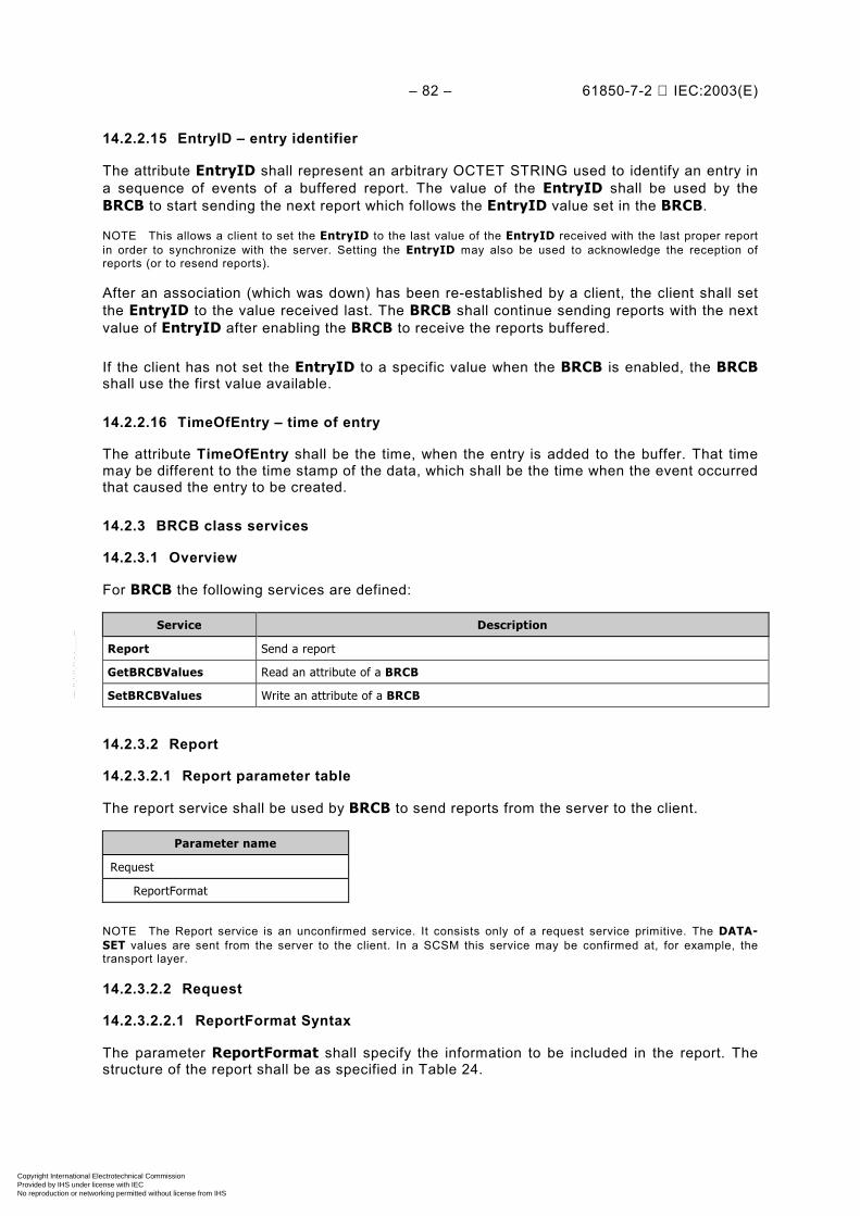
– 82 – 61850-7-2 IEC:2003(E)
14.2.2.15 EntryID – entry identifier
The attribute EntryID shall represent an arbitrary OCTET STRING used to identify an entry ina sequence of events of a buffered report. The value of the EntryID shall be used by theBRCB to start sending the next report which follows the EntryID value set in the BRCB.
NOTE This allows a client to set the EntryID to the last value of the EntryID received with the last proper reportin order to synchronize with the server. Setting the EntryID may also be used to acknowledge the reception ofreports (or to resend reports).
After an association (which was down) has been re-established by a client, the client shall setthe EntryID to the value received last. The BRCB shall continue sending reports with the nextvalue of EntryID after enabling the BRCB to receive the reports buffered.
If the client has not set the EntryID to a specific value when the BRCB is enabled, the BRCBshall use the first value available.
14.2.2.16 TimeOfEntry – time of entry
The attribute TimeOfEntry shall be the time, when the entry is added to the buffer. That timemay be different to the time stamp of the data, which shall be the time when the event occurredthat caused the entry to be created.
14.2.3 BRCB class services
14.2.3.1 Overview
For BRCB the following services are defined:
Service Description
Report Send a report
GetBRCBValues Read an attribute of a BRCB
SetBRCBValues Write an attribute of a BRCB
14.2.3.2 Report
14.2.3.2.1 Report parameter table
The report service shall be used by BRCB to send reports from the server to the client.
Parameter name
Request
ReportFormat
NOTE The Report service is an unconfirmed service. It consists only of a request service primitive. The DATA-SET values are sent from the server to the client. In a SCSM this service may be confirmed at, for example, thetransport layer.
14.2.3.2.2 Request
14.2.3.2.2.1 ReportFormat Syntax
The parameter ReportFormat shall specify the information to be included in the report. Thestructure of the report shall be as specified in Table 24.
Copyright International Electrotechnical Commission Provided by IHS under license with IEC
Not for ResaleNo reproduction or networking permitted without license from IHS
--``````-`-`,,`,,`,`,,`---
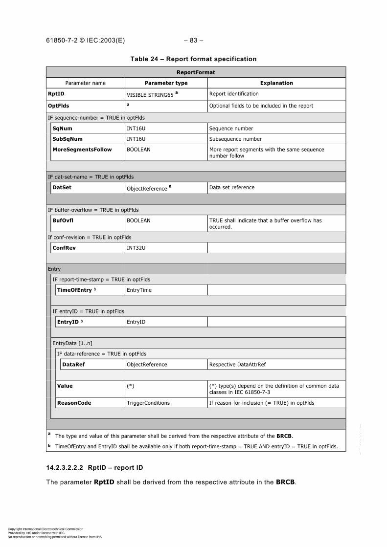
61850-7-2 © IEC:2003(E) – 83 –
Table 24 – Report format specification
ReportFormat
Parameter name Parameter type Explanation
RptID VISIBLE STRING65 a Report identification
OptFlds a Optional fields to be included in the report
IF sequence-number = TRUE in optFlds
SqNum INT16U Sequence number
SubSqNum INT16U Subsequence number
MoreSegmentsFollow BOOLEAN More report segments with the same sequencenumber follow
IF dat-set-name = TRUE in optFlds
DatSet ObjectReference a Data set reference
IF buffer-overflow = TRUE in optFlds
BufOvfl BOOLEAN TRUE shall indicate that a buffer overflow hasoccurred.
If conf-revision = TRUE in optFlds
ConfRev INT32U
Entry
IF report-time-stamp = TRUE in optFlds
TimeOfEntry b EntryTime
IF entryID = TRUE in optFlds
EntryID b EntryID
EntryData [1..n]
IF data-reference = TRUE in optFlds
DataRef ObjectReference Respective DataAttrRef
Value (*) (*) type(s) depend on the definition of common dataclasses in IEC 61850-7-3
ReasonCode TriggerConditions If reason-for-inclusion (= TRUE) in optFlds
a The type and value of this parameter shall be derived from the respective attribute of the BRCB.
b TimeOfEntry and EntryID shall be available only if both report-time-stamp = TRUE AND entryID = TRUE in optFlds.
14.2.3.2.2.2 RptID – report ID
The parameter RptID shall be derived from the respective attribute in the BRCB.
Copyright International Electrotechnical Commission Provided by IHS under license with IEC
Not for ResaleNo reproduction or networking permitted without license from IHS
--``````-`-`,,`,,`,`,,`---

– 84 – 61850-7-2 IEC:2003(E)
14.2.3.2.2.3 OptFlds – optional fields to include in report
The parameter OptFlds shall specify which of the optional fields (sequence-number, report-time-stamp, reason-for-inclusion, data-set-name, data-reference, buffer-overflow, orentryID) are included in the Report.
The parameter OptFlds shall be derived from the attribute OptFlds of the respective BRCB.
14.2.3.2.2.4 SqNum – sequence number
The BRCB that has report enable set to TRUE shall maintain the parameter SqNum. Thisnumber shall be incremented by the BRCB for each report generated and sent on the basis ofthe BRCB. The increment shall occur once the BRCB has formatted the report fortransmission. The first report following the setting of the report enable to TRUE shall containsequence number 0. The sequence number shall roll over to 0 at its maximal value.
The sequence number shall be included in the report if the optional fields to include in reportattribute (OptFlds) of the BRCB includes the sequence-number (=TRUE); otherwise, it shall beomitted. Figure 22 gives an example of report generation and sequence number.
Report control block
REPORT-CONTROL- Blocksend reports with
sequencenumbers
Logical Node
Procedure controlling thesequence numbering(initializing, incrementing,rolling over, ..)
SetRCBValue<...
Attribute „optFlds”: ...sequence-number = TRUE
Report<... SqNum = 0
value ...> Report<... SqNum = 1
value ...> Report<... SqNum = 2
value ...>
Figure 22 – Report example on the use of sequence number
14.2.3.2.2.5 SubSqNum – subsequence number
For the case of long reports that do not fit into one message, a single report shall be dividedinto subreports. Each segment – of one report – shall be numbered with the same sequencenumber and a unique SubSqNum.
The BRCB shall maintain a subsequence number for each report. This number shall beincremented for each subreport generated and sent based upon the report control instance.The increment shall occur once the server has formatted the subreports and queued the sub-report to the next lower protocol layer. The first subreport of the report shall have asubsequence number of zero. The subsequence number shall roll over to 0 after all subreportsof one specific report have been queued.
The subsequence number shall be included in the report if the optional fields to include inreport attribute (OptFlds) of the BRCB includes sequence-number (=TRUE); otherwise, itshall be omitted.
If a BRCB does not support sequence numbering then an attempt to set the sequence-number of the OptFlds attribute to TRUE shall cause a negative response of theSetBRCBValues service.
IEC 417/03
Copyright International Electrotechnical Commission Provided by IHS under license with IEC
Not for ResaleNo reproduction or networking permitted without license from IHS
--``````-`-`,,`,,`,`,,`---

61850-7-2 © IEC:2003(E) – 85 –
14.2.3.2.2.6 MoreSegmentsFollow – more report segments follow
The parameter MoreSegmentsFollow indicates that more report segments with the samesequence number follow.
14.2.3.2.2.7 DatSet – data set reference
The parameter DatSet shall be derived from the respective attribute in the BRCB.
14.2.3.2.2.8 BufOvl – buffer overflow occurred
The parameter BufOvl shall indicate to the client that a buffer overflow occurred. The BRCBshall set this field in the first report that is sent with events that occurred after the overflow.
14.2.3.2.2.9 Entry
TimeOfEntry – report time stamp
The parameter TimeOfEntry shall specify the time at which the report was generated. TheTimeOfEntry shall be included in the report if the optional fields to include attribute (OptFlds)of the BRCB includes report-time-stamp (=TRUE), otherwise it shall be omitted.
NOTE The event “time at which the report was generated” is determined by a specific implementation.
If the BRCB does not support TimeOfEntry then an attempt to set the report-time-stamp of theOptFlds attribute to TRUE shall cause a negative response of the SetBRCBValues service.
Reports with the same sequence number but different subsequence numbers shall use thesame TimeOfEntry.
EntryID – entry identifier
The parameter EntryID shall represent an arbitrary OCTET STRING used to identify an entryin a sequence of events of a BRCB.
EntryData [1..n]
The parameter EntryData shall contain the data reference, value, and reasonCode of eachmember of the DATA-SET to be included in the report. The value shall comprise the value ofall data attributes of the member of DATA-SET.
DataRefThe parameter DataRef shall contain the functional constrained data (FCD) of theDataAttribute values included in the report.
ValueThe parameter Value shall contain the DataAttribute values included in the report.
The number of members of the DATA-SET whose values shall be included in the reportshall depend on the control attribute buffer time (BufTm) and the occurrences of internalevents.
BufTm = 0In case of (BufTm = 0) only the value of the member of a DATA-SET shall be includedthat produced the internal event.EXAMPLE The data attribute stVal of the DATA MyLD/XCBR1.Pos (Position) in Figure 23 is referenced intwo different DATA-SETs. The figure displays two different instances that reference the data attributes ofthe position. In the left case the DATA-SET references 9 individual DATA-SET members (all of functional
Copyright International Electrotechnical Commission Provided by IHS under license with IEC
Not for ResaleNo reproduction or networking permitted without license from IHS
--``````-`-`,,`,,`,`,,`---
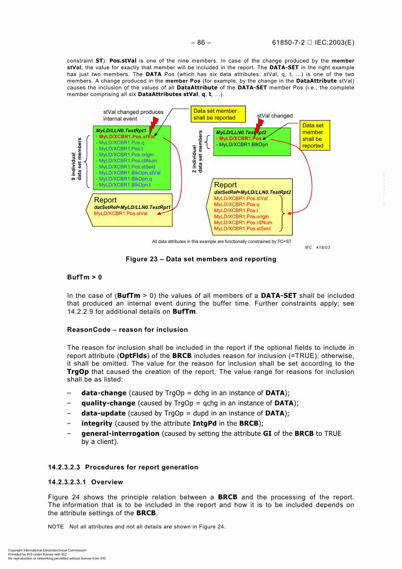
– 86 – 61850-7-2 IEC:2003(E)
constraint ST): Pos.stVal is one of the nine members. In case of the change produced by the memberstVal, the value for exactly that member will be included in the report. The DATA-SET in the right examplehas just two members. The DATA Pos (which has six data attributes: stVal, q, t, ...) is one of the twomembers. A change produced in the member Pos (for example, by the change in the DataAttribute stVal)causes the inclusion of the values of all DataAttribute of the DATA-SET member Pos (i.e., the completemember comprising all six DataAttributes stVal, q, t, ...).
MyLD/LLN0.TestRpt1- MyLD/XCBR1.Pos.stVal- MyLD/XCBR1.Pos.q- MyLD/XCBR1.Pos.t- MyLD/XCBR1.Pos.origin- MyLD/XCBR1.Pos.ctlNum- MyLD/XCBR1.Pos.stSeld- MyLD/XCBR1.BlkOpn.stVal- MyLD/XCBR1.BlkOpn.q- MyLD/XCBR1.BlkOpn.t
ReportdatSetRef=MyLD/LLN0.TestRpt1MyLD/XCBR1.Pos.stVal
9 in
divi
dual
data
set
mem
bers
MyLD/LLN0.TestRpt2- MyLD/XCBR1.Pos- MyLD/XCBR1.BlkOpn
ReportdatSetRef=MyLD/LLN0.TestRpt2MyLD/XCBR1.Pos.stValMyLD/XCBR1.Pos.qMyLD/XCBR1.Pos.tMyLD/XCBR1.Pos.originMyLD/XCBR1.Pos.ctlNumMyLD/XCBR1.Pos.stSeld
Data set membershall be reported
Data setmembershall bereported
2 in
divi
dual
da
ta s
et m
embe
rs
stVal changed producesinternal event stVal changed
All data attributes in this example are functionally constrained by FC=ST
Figure 23 – Data set members and reporting
BufTm > 0
In the case of (BufTm > 0) the values of all members of a DATA-SET shall be includedthat produced an internal event during the buffer time. Further constraints apply; see14.2.2.9 for additional details on BufTm.
ReasonCode – reason for inclusion
The reason for inclusion shall be included in the report if the optional fields to include inreport attribute (OptFlds) of the BRCB includes reason for inclusion (=TRUE); otherwise,it shall be omitted. The value for the reason for inclusion shall be set according to theTrgOp that caused the creation of the report. The value range for reasons for inclusionshall be as listed:
– data-change (caused by TrgOp = dchg in an instance of DATA);– quality-change (caused by TrgOp = qchg in an instance of DATA);– data-update (caused by TrgOp = dupd in an instance of DATA);– integrity (caused by the attribute IntgPd in the BRCB);– general-interrogation (caused by setting the attribute GI of the BRCB to TRUE
by a client).
14.2.3.2.3 Procedures for report generation
14.2.3.2.3.1 Overview
Figure 24 shows the principle relation between a BRCB and the processing of the report.The information that is to be included in the report and how it is to be included depends onthe attribute settings of the BRCB.
NOTE Not all attributes and not all details are shown in Figure 24.
IEC 418/03
Copyright International Electrotechnical Commission Provided by IHS under license with IEC
Not for ResaleNo reproduction or networking permitted without license from IHS
--``````-`-`,,`,,`,`,,`---
61850-7-2 © IEC:2003(E) – 87 –
BUFFERED-REPORT-CONTROL-BLOCKBRCNameRptEnaRptIDOptFlds
sequence-number report-time-stampreason-for-inclusiondata-set-namedata-reference
DatSetGIBufTmTrgOps
data-changequality-changedata-updateintegrity
IntgPd
DataSet to bemonitored and reported
DS „SUM“ { data object „A“
data object „B“}
en dis
„B“ <399.15> „SUM“
Report
Sequence4 data-change„MyReport“ 12:00:03
BRCBRefrptEnaDatSet GI BufTmTrgOpsIntgPdRptIDOptFlds
...
SetURCValue
Client Server
- data-change- quality-change- data-update- integrity- general interrogation
en - enabledis - disable
„B“ <400.09> „SUM“Sequence5 data-change„MyReport“ 12:00:13
...
Figure 24 – Report example
Pre-condition
A BRCB shall have been configured and enabled for reporting and shall have an establishedassociation with the client to which the information is to be reported.
14.2.3.2.3.2 Data-change, quality-change, and data-update
These three trigger options support report generation based on change or update in a value ofa DataAttribute of a member of a DATA-SET.
data-change
The trigger option data-change (TrgOp = dchg) relates to a change in a value of aDataAttribute representing the process-related value of the data. If the TrgOp (= dchg) isFALSE then no report should be issued on a data-change in the value of that DataAttribute.
quality-change
The trigger option quality-change (TrgOp = qchg) relates to a change in the quality value ofa DataAttribute. If the TrgOp (= qchg) is FALSE then no report should be issued on a data-change in the value of that DataAttribute.
IEC 419/03
Copyright International Electrotechnical Commission Provided by IHS under license with IEC
Not for ResaleNo reproduction or networking permitted without license from IHS
--``````-`-`,,`,,`,`,,`---

– 88 – 61850-7-2 IEC:2003(E)
data-update
The trigger option data-update (TrgOp = dupd) relates to a freeze event in a value of aDataAttribute representing a freeze value of the data (for example, frozen counters) or to anevent triggered by updating the value of a DataAttribute. If the TrgOp (= dupd) is FALSEthen no report should be issued on a data-change in the value of that DataAttribute.
NOTE 1 Data-update trigger condition may be used to issue sending a report or storing a log entry into a log whena value of a DataAttribute has updated. Updating may mean that the value has changed or has been “overwritten”with the same value as before. The dupd trigger condition can be used as a trigger for statistics values that may becalculated and updated on a periodic base. Independently of whether the statistics value has changed or not, thevalue will be reported or logged.
NOTE 2 With the specification of the common data classes in IEC 61850-7-3, the trigger option applying toa specific DataAttribute is defined.
When the BRCB is notified by an internal event of a data-change, quality-change, or data-update event of a member of the referenced DATA-SET whose values are to be reported, theBRCB shall include the value of the member of the referenced DATA-SET that producedthe internal event in the report according to 14.2.3.2.2.9. The value to be reported shall be thevalue at the time when the internal event occurred.
NOTE 3 For changes that meet more than one TrgOp criteria (for example, data-change and quality-change),it is preferable to send only a single report in such a case.
14.2.3.2.3.3 Integrity
The trigger option integrity supports integrity report generation. In addition, to activate thistrigger option (set TrgOp integrity to TRUE), a client shall set the integrity period (IntgPd)to a value greater than 0. When integrity reports are enabled, the BRCB shall be notifiedeach time the value of the time as specified in IntgPd has expired. The BRCB shall thenbuild a report with the values of all members of the referenced DATA-SET. If the TrgOp(= integrity) is FALSE then no integrity report should be issued.
All buffered events shall be sent before integrity reports can be sent.
A new internal event caused by data-change, quality-change, or data-update (while thetransmission of the integrity report is still going on) shall use a new sequence number (andsubsequence number starting with 0) and may pass the remaining segments of the integrityreport that is still going on.
A new event caused by integrity time (while the transmission of the integrity report is still goingon) shall be interpreted as a mis-configured BRCB. The new event shall have no effect.
A new general-interrogation request (while the transmission of the integrity report is stillgoing on) shall be deferred until the ongoing transmission of the integrity report has completed.A new general-interrogation report with a new sequence number (and subsequence numberstarting with 0) shall be generated and sent.
14.2.3.2.3.4 General interrogation (GI)
The attribute general interrogation (GI) shall be used to indicate the request of a generalinterrogation. After setting the attribute GI to TRUE the BRCB shall start the interrogationprocess and create a report that includes all DataAttribute values of the referenced DATA-SET. After initiation of the interrogation process the BRCB shall automatically set the value ofGI to FALSE. If the TrgOp (= general-interrogation) is FALSE then no integrity reportshould be issued.
All buffered events shall be sent before general-interrogation reports can be sent.
Copyright International Electrotechnical Commission Provided by IHS under license with IEC
Not for ResaleNo reproduction or networking permitted without license from IHS
--``````-`-`,,`,,`,`,,`---

61850-7-2 © IEC:2003(E) – 89 –
A new request for general-interrogation (while the transmission of the general-interrogation report is still going on) shall stop sending the remaining segments of thegeneral-interrogation report that is still going on. A new general-interrogation report witha new sequence number (and subsequence number starting with 0) shall be generated andsent.
A new event caused by integrity time (while the transmission of the general-interrogationreport is still going on) shall be deferred until the ongoing transmission of the general-interrogation report has completed.
NOTE The general-interrogation is initiated by the client. The integrity report, which also transmits all values ofa data set, is initiated by the BRCB.
14.2.3.2.3.5 Time sequence order of reports
The BRCB within the implementation resource limits shall send all reports in the time sequenceorder in which the related internal events have been made available.
Reports generated as result of the trigger options integrity or general-interrogation providea snapshot of the values of all members of the DATA-SET. The transmission of these reportsshall start with the next sequence number. If all values of the referenced data set do not fit intoone single report, several subreports with incremented subsequence number (starting withsubsequence number equal shall be sent until all values have been sent. If – while sendingthese reports or subreports respectively – DATA values caused by data-change, quality-change, or data-update need to be sent, this may be done with a new report sent in-betweenthe transmission of the integrity or general-interrogation reports (subreports) respectivelyusing a new sequence number. In that case, the time sequence order is not maintained, but thehigher sequence number may be used by the client to determine the newer values.
NOTE This allows a client to keep a process data image consistent when a report is received while a general-interrogation is in progress. The client needs to keep track of the sequence numbers. When receiving informationfor a specific data in a report with sequence number (for example, 22) older than the sequence number (forexample, 23) of a previously received report with the same data, the client may not use this information to updatethe process data image.
14.2.3.2.3.6 Buffering events
The BRCB shall buffer events based on the trigger options data-change, quality-change,data-update, and integrity during loss of association.
After the association is available again, after the client has set the EntryID, and enabled theBRCB, the BRCB shall start sending the reports of events that have been buffered. The BRCBshall use the sequence and subsequence numbers so that no gaps occur.
14.2.3.3 GetBRCBValues
14.2.3.3.1 GetBRCBValues parameter table
A client shall use the GetBRCBValues service to retrieve attribute values of BRCB madevisible and thus accessible to the requesting client by the referenced LOGICAL-NODE.
Copyright International Electrotechnical Commission Provided by IHS under license with IEC
Not for ResaleNo reproduction or networking permitted without license from IHS
--``````-`-`,,`,,`,`,,`---
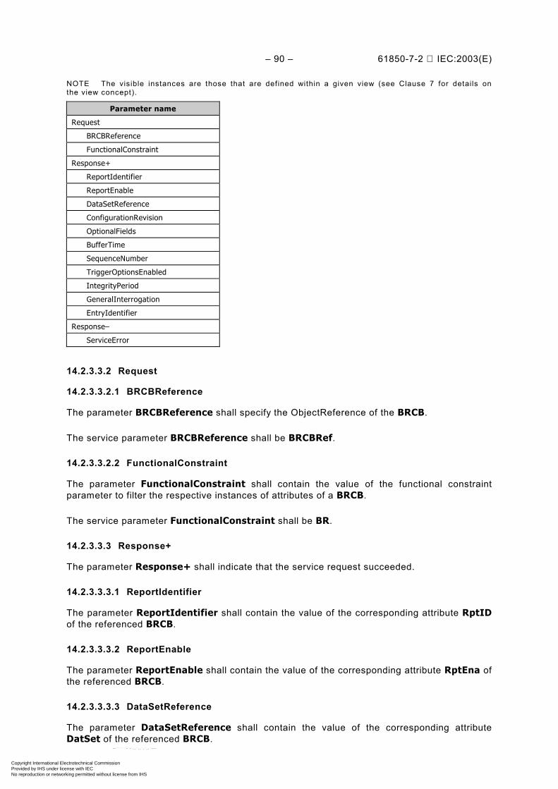
– 90 – 61850-7-2 IEC:2003(E)
NOTE The visible instances are those that are defined within a given view (see Clause 7 for details onthe view concept).
Parameter name
Request
BRCBReference
FunctionalConstraint
Response+
ReportIdentifier
ReportEnable
DataSetReference
ConfigurationRevision
OptionalFields
BufferTime
SequenceNumber
TriggerOptionsEnabled
IntegrityPeriod
GeneralInterrogation
EntryIdentifier
Response–
ServiceError
14.2.3.3.2 Request
14.2.3.3.2.1 BRCBReference
The parameter BRCBReference shall specify the ObjectReference of the BRCB.
The service parameter BRCBReference shall be BRCBRef.
14.2.3.3.2.2 FunctionalConstraint
The parameter FunctionalConstraint shall contain the value of the functional constraintparameter to filter the respective instances of attributes of a BRCB.
The service parameter FunctionalConstraint shall be BR.
14.2.3.3.3 Response+
The parameter Response+ shall indicate that the service request succeeded.
14.2.3.3.3.1 ReportIdentifier
The parameter ReportIdentifier shall contain the value of the corresponding attribute RptIDof the referenced BRCB.
14.2.3.3.3.2 ReportEnable
The parameter ReportEnable shall contain the value of the corresponding attribute RptEna ofthe referenced BRCB.
14.2.3.3.3.3 DataSetReference
The parameter DataSetReference shall contain the value of the corresponding attributeDatSet of the referenced BRCB.
Copyright International Electrotechnical Commission Provided by IHS under license with IEC
Not for ResaleNo reproduction or networking permitted without license from IHS
--``````-`-`,,`,,`,`,,`---

61850-7-2 © IEC:2003(E) – 91 –
14.2.3.3.3.4 ConfigurationRevision
The parameter ConfigurationRevision shall contain the value of the corresponding attributeConfRev of the referenced BRCB.
14.2.3.3.3.5 OptionalFields
The parameter OptionalFields shall contain the value of the corresponding attribute OptFldsof the referenced BRCB.
14.2.3.3.3.6 BufferTime
The parameter BufferTime shall contain the value of the corresponding attribute BufTm of thereferenced BRCB.
14.2.3.3.3.7 SequenceNumber
The parameter SequenceNumber shall contain the value of the corresponding attributeSqNum of the referenced BRCB.
14.2.3.3.3.8 TriggerOptionsEnabled
The parameter TriggerOptionsEnabled shall contain the value of the corresponding attributeTrgOp of the referenced BRCB.
14.2.3.3.3.9 IntegrityPeriod
The parameter IntegrityPeriod shall contain the value of the corresponding attribute IntgPdof the referenced BRCB.
14.2.3.3.3.10 GeneralInterrogation
The parameter GeneralInterrogation shall contain the value of the corresponding attributeGI of the referenced BRCB.
14.2.3.3.3.11 EntryIdentifier
The parameter EntryIdentifier shall contain the value of the corresponding attribute EntryIDof the referenced BRCB.
14.2.3.3.4 Response–
The Response– parameter shall indicate that the service request failed. The appropriateServiceError shall be returned.
14.2.3.4 SetBRCBValues
14.2.3.4.1 SetBRCBValues parameter table
A client shall use the SetBRCBValues service to set attribute values of BRCB made visibleand thus accessible to the requesting client by the referenced LOGICAL-NODE.
Copyright International Electrotechnical Commission Provided by IHS under license with IEC
Not for ResaleNo reproduction or networking permitted without license from IHS
--``````-`-`,,`,,`,`,,`---

– 92 – 61850-7-2 IEC:2003(E)
NOTE The visible instances are those that are defined within a given view (see Clause 7 for details onthe view concept).
Parameter name
Request
BRCBReference
FunctionalConstraint
ReportIdentifier [0..1]
ReportEnable [0..1]
DataSetReference [0..1]
OptionalFields [0..1]
BufferTime [0..1]
TriggerOptionsEnabled [0..1]
IntegrityPeriod [0..1]
GeneralInterrogation [0..1]
PurgeBuffer [0..1]
EntryIdentifier [0..1]
Response+
Response–
ServiceError
14.2.3.4.2 Request
14.2.3.4.2.1 BRCBReference
The parameter BRCBReference shall specify the ObjectReference of the BRCB.
The service parameter BRCBReference shall be BRCBRef.
14.2.3.4.2.2 FunctionalConstraint
The parameter FunctionalConstraint shall contain the value of the functional constraintparameter to filter the respective attributes of a BRCB.
The service parameter FunctionalConstraint shall be BR.
14.2.3.4.2.3 ReportIdentifier [0..1]
The parameter ReportIdentifier shall contain the value for the corresponding attribute RptIDof the referenced BRCB.
14.2.3.4.2.4 ReportEnable [0..1]
The parameter ReportEnable shall contain the value for the corresponding attribute RptEnaof the referenced BRCB.
14.2.3.4.2.5 DataSetReference [0..1]
The parameter DataSetReference shall contain the value for the corresponding attributeDatSet of the referenced BRCB.
Copyright International Electrotechnical Commission Provided by IHS under license with IEC
Not for ResaleNo reproduction or networking permitted without license from IHS
--``````-`-`,,`,,`,`,,`---
61850-7-2 © IEC:2003(E) – 93 –
14.2.3.4.2.6 OptionalFields [0..1]
The parameter OptionalFields shall contain the value for the corresponding attribute OptFldsof the referenced BRCB.
14.2.3.4.2.7 BufferTime [0..1]
The parameter BufferTime shall contain the value for the corresponding attribute BufTm ofthe referenced BRCB.
14.2.3.4.2.8 TriggerOptionsEnabled [0..1]
The parameter TriggerOptions shall contain the value for the corresponding attribute TrgOpof the referenced BRCB.
14.2.3.4.2.9 IntegrityPeriod [0..1]
The parameter IntegrityPeriod shall contain the value for the corresponding attribute IntgPdof the referenced BRCB.
14.2.3.4.2.10 GeneralInterrogation [0..1]
The parameter GeneralInterrogation shall contain the value for the corresponding attributeGI of the referenced BRCB.
14.2.3.4.2.11 PurgeBuffer [0..1]
The parameter PurgeBuffer shall contain the value for the corresponding attribute PurgeBufof the referenced BRCB.
14.2.3.4.2.12 EntryIdentifier
The parameter EntryIdentifier shall contain the value of the corresponding attribute EntryIDof the referenced BRCB.
14.2.3.4.3 Response+
The parameter Response+ shall indicate that the service request succeeded.
14.2.3.4.4 Response–
The parameter Response– shall indicate that the service request failed. The appropriateServiceError shall be returned.
This service shall return a failure if the service has been issued for any attribute of a BRCBother than setting the RptEna to FALSE while BRCB is enabled.
Copyright International Electrotechnical Commission Provided by IHS under license with IEC
Not for ResaleNo reproduction or networking permitted without license from IHS
--``````-`-`,,`,,`,`,,`---

– 94 – 61850-7-2 IEC:2003(E)
14.2.4 UNBUFFERED-REPORT-CONTROL-BLOCK (URCB) class definition
14.2.4.1 URCB class Syntax
The URCB class shall have the structure defined in Table 25.
Table 25 – URCB class definition
URCB class
Attribute name Attribute type FC TrgOp Value/value range/explanation
URCBName ObjectName - - Instance name of an instance of URCB
URCBRef ObjectReference - - Path-name of an instance of URCB
Specific to report handler
RptID VISIBLE STRING65 RP -
RptEna BOOLEAN RP dchg
Resv BOOLEAN RP -
DatSet ObjectReference RP dchg
ConfRev INT32U RP dchg
OptFlds PACKED LIST RP dchg
reserved BOOLEAN
sequence-number BOOLEAN
report-time-stamp BOOLEAN
reason-for-inclusion BOOLEAN
data-set-name BOOLEAN
data-reference BOOLEAN
reserved BOOLEAN Used for buffer-overflow in BRCB
reserved BOOLEAN Used for entryID in BRCB
conf-revision BOOLEAN
BufTm INT32U RP dchg 0 .. MAX
SqNum INT8U RP -
TrgOp TriggerConditions RP dchg
IntgPd INT32U RP dchg 0.. MAX
GI BOOLEAN BR -
ServicesReportGetURCBValuesSetURCBValues
Except URCBName, URCBRef, RptEna, and Resv all other attributes shall be as defined forthe BRCB in 14.2.2.
14.2.4.2 URCBName – unbuffered report control name
The attribute URCBName shall be the name of the URCB that unambiguously identifies theURCB within LOGICAL-NODE.
14.2.4.3 URCBRef – unbuffered report control ObjectReference
The attribute URCBRef shall be the unique path-name of URCB.
Copyright International Electrotechnical Commission Provided by IHS under license with IEC
Not for ResaleNo reproduction or networking permitted without license from IHS
--``````-`-`,,`,,`,`,,`---
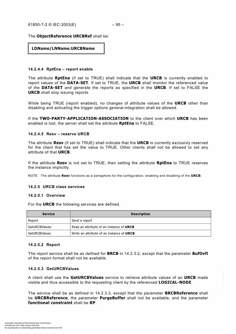
61850-7-2 © IEC:2003(E) – 95 –
The ObjectReference URCBRef shall be:
LDName/LNName.URCBName
14.2.4.4 RptEna – report enable
The attribute RptEna (if set to TRUE) shall indicate that the URCB is currently enabled toreport values of the DATA-SET. If set to TRUE, the URCB shall monitor the referenced valueof the DATA-SET and generate the reports as specified in the URCB. If set to FALSE theURCB shall stop issuing reports.
While being TRUE (report enabled), no changes of attribute values of the URCB other thandisabling and activating the trigger options general-integration shall be allowed.
If the TWO-PARTY-APPLICATION-ASSOCIATION to the client over which URCB has beenenabled is lost, the server shall set the attribute RptEna to FALSE.
14.2.4.5 Resv – reserve URCB
The attribute Resv (if set to TRUE) shall indicate that the URCB is currently exclusivly reservedfor the client that has set the value to TRUE. Other clients shall not be allowed to set anyattribute of that URCB.
If the attribute Resv is not set to TRUE, then setting the attribute RptEna to TRUE reservesthe instance implicitly.
NOTE The attribute Resv functions as a semaphore for the configuration, enabling and disabling of the URCB.
14.2.5 URCB class services
14.2.5.1 Overview
For the URCB the following services are defined.
Service Description
Report Send a report
GetURCBValues Read an attribute of an instance of URCB
SetURCBValues Write an attribute of an instance of URCB
14.2.5.2 Report
The report service shall be as defined for BRCB in 14.2.3.2, except that the parameter BufOvflof the report format shall not be available.
14.2.5.3 GetURCBValues
A client shall use the GetURCBValues service to retrieve attribute values of an URCB madevisible and thus accessible to the requesting client by the referenced LOGICAL-NODE.
The service shall be as defined in 14.2.3.3, except that the parameter BRCBReference shallbe URCBReference, the parameter PurgeBuffer shall not be available, and the parameterfunctional constraint shall be RP.
Copyright International Electrotechnical Commission Provided by IHS under license with IEC
Not for ResaleNo reproduction or networking permitted without license from IHS
--``````-`-`,,`,,`,`,,`---

– 96 – 61850-7-2 IEC:2003(E)
14.2.5.4 SetURCBValues
A client shall use the SetURCBValues service to set attribute values of URCB made visibleand thus accessible to the requesting client by the referenced LOGICAL-NODE.
The service shall be as defined in 14.2.3.4, except that the parameter BRCBReference shallbe URCBReference, the parameter PurgeBuffer shall not be available, and the parameterfunctional constraint shall be RP.
14.3 LOG-CONTROL-BLOCK class model
14.3.1 General
14.3.1.1 Basic concepts
Many IEDs have requirements for the internal storage of historical data values and retrievalover communications systems. This data values fall into two general categories: periodicrecordings (commonly referred to in metering applications as profiles) and event-triggered or“sequence-of-events” (SOE) data. Several criteria are be used to differentiate historical datalogging requirements from report-oriented information transfer.– Data logging shall be independent of external application associations or other communication
transactions. Even if communication is lost, historical events shall occur and shall be logged.– The process of storing the historical records is completely asynchronous with retrieval over
communications.– The rate of generation of historical records can in some cases be much faster than the
ability of communication processes to report the values to an external data base.– Record retrieval shall allow external applications to request subsets of the entire historical
data base for the purpose of maintaining an external, complete time or event-sequencedhistorical record.
– The source of the data may be external to the device. Thus, the historical repository maysimply be a central point of storage.
– Records have relative significance with regard to time or ordering and may require theassignment of a sequence number.
LN uv
LCB “A” - LCB Attributes
LOG- OldEntrTm- NewEntrTm- OldEntr- NewEntr
- Log Entry- Log Entry- Log Entry- Log Entry- Log Entry
LCB “B” - LCB Attributes
LD B
GetLCBValues
SetLCBValues
GetLogStatusValues
QueryLog
LN xy
GetLCBValues
SetLCBValues
LD A
Server
Figure 25 – Log model overviewIEC 420/03
Copyright International Electrotechnical Commission Provided by IHS under license with IEC
Not for ResaleNo reproduction or networking permitted without license from IHS
--``````-`-`,,`,,`,`,,`---

61850-7-2 © IEC:2003(E) – 97 –
Figure 25 gives an overview of the LOG and LCB classes. One LOG may be controlled bymultiple LCBs.
14.3.1.2 The log buffer concept
From an implementation view, the LOG may be considered as a circular buffer that overwritesthe oldest values in the LOG. However, this is hidden from the client. The client view of theLOG is a linear buffer, where the LOG entries are identified by
– EntryID: a unique identifier of a LOG entry;
– TimeOfEntry: the time, when the LOG entry has been added to the LOG.
EntryID shall be a counter that rolls over when the maximal value has been reached. The sizeof that counter shall be larger than the maximal number of entries that can be stored in a LOGso that there may not be two entries in the log with the same value of entryID. EntryIDtogether with TimeOfEntry provide a unique identification of the entry.
A client may query the LOG by entryID or by TimeOfEntry.
14.3.2 LCB class definition
14.3.2.1 LCB class syntax
The LCB shall control the procedures that are required for storing values of DataAttribute(the log entry) into a LOG. Each enabled LCB shall associate DATA-SET with a LOG. Changesin a value of a member of a DATA-SET shall be stored as LOG entry. Multiple LCBs allowmultiple DATA-SETs to feed a LOG.
It shall be the responsibility of access control, to prevent unauthorized clients to modify an LCB.
NOTE The internal notification, local storage mechanism, internal formats, etc. for log entries are all local issuesand outside the scope of this part of IEC 61850.
The LCB shall have the structure specified in Table 26.
Table 26 – LCB class definition
LCB class
Attribute name Attribute type FC TrgOp Value/value range/explanation
LCBName ObjectName - - Instance name of an instance of LCB
LCBRef ObjectReference - - Path-name of an instance of LCB
Specific to log handler
LogEna BOOLEAN LG dchg
DatSet ObjectReference LG dchg
OptFlds PACKED LIST LG dchg
reason-for-inclusion BOOLEAN
TrgOp TriggerConditions LG dchg Valid values for TrgOp of type TriggerConditionsshall be dchg, qchg, dupd, and integrity.
IntgPd INT32U LG dchg 1..MAX; 0 implies no integrity logging.
Specific to building the log
LogRef ObjectReference LG
ServicesGetLCBValuesSetLCBValues
Copyright International Electrotechnical Commission Provided by IHS under license with IEC
Not for ResaleNo reproduction or networking permitted without license from IHS
--``````-`-`,,`,,`,`,,`---
– 98 – 61850-7-2 IEC:2003(E)
14.3.2.2 LCB class attributes
14.3.2.2.1 LCBName – log control name
The attribute LCBName shall unambiguously identify a LCB within the scope of a LOGICAL-NODE.
14.3.2.2.2 LCBRef – log control ObjectReference
The attribute LCBRef shall be the unique path-name of a LCB.
The ObjectReference LCBRef shall be:
LDName/LNName.LCBName
14.3.2.2.3 LogEna – log enable
The attribute LogEna shall indicate that this LCB is recording into the LOG specified byLogRef.
A transition of LogEna from disabled to enabled or from enabled to disabled shall cause a logentry to be placed into the LOG.
NOTE The attribute LogEna may be set to TRUE automatically by a server after turning the server on.
While in the state enabled no changes of attribute values of LCB other than disabling shallbe allowed.
14.3.2.2.4 DatSet – data set reference
The attribute DatSet shall indicate the DATA-SET, whose member values are to be logged.
14.3.2.3 OptFlds – optional fields to include in log
The attribute OptFlds shall be the client-specified optional fields to be included in the logissued by this LCB. This attribute defines a subset of the optional header fields of the logEntryData (see 14.3.3.1) that shall be included in the log:
– reason-for-inclusion (if TRUE ReasonCode shall be included in the log);
If a LCB does not support the above option, then an attempt to set the corresponding bit toTRUE shall cause a negative response of the SetLCBValues service.
14.3.2.3.1 TrgOp – trigger options
The attribute TrgOp shall specify the trigger conditions that shall be monitored by this LCB tocause a Log entry to be created. The values defined are the same as for reporting (see14.2.2.11).
The TrgOp general-interrogation shall not be supported for logging.
14.3.2.3.2 IntgPd – integrity period
If TrgOp is set to integrity, the attribute IntgPd indicates the period in milliseconds used forlogging caused by integrity scans.
Copyright International Electrotechnical Commission Provided by IHS under license with IEC
Not for ResaleNo reproduction or networking permitted without license from IHS
--``````-`-`,,`,,`,`,,`---

61850-7-2 © IEC:2003(E) – 99 –
14.3.2.3.3 LogRef – log reference
The attribute LogRef shall be the reference of the LOG to which values of members of thereferenced DATA-SET shall be recorded.
14.3.2.4 LCB services – Overview
For the LCB the following services are defined:
Service Description
GetLCBValues Retrieve the attribute values of a LCB
SetLCBValues Set the attributes values of a LCB
14.3.2.5 GetLCBValues
A client shall use the GetLCBValues service to retrieve attribute values of LCB made visibleand thus accessible to the requesting client by the referenced LOGICAL-NODE.
NOTE The visible instances are those that are defined within a given view (see Clause 7 for details on theview concept).
Parameter name
Request
LCBReference
FunctionalConstraint
Response+
LogEnable
DataSetReference
TriggerOptions
IntegrityPeriod
LogReference
Response–
ServiceError
14.3.2.5.1 Request
14.3.2.5.1.1 LCBReference
The parameter LCBReference shall specify the ObjectReference of the LCB.
The service parameter LCBReference shall be LCBRef.
14.3.2.5.1.2 FunctionalConstraint
The parameter FunctionalConstraint shall contain the value of the functional constraintparameter to filter the respective instances of attributes of a LCB.
The service parameter FunctionalConstraint shall be LG (logging).
14.3.2.5.2 Response+
The parameter Response+ shall indicate that the service request succeeded.
Copyright International Electrotechnical Commission Provided by IHS under license with IEC
Not for ResaleNo reproduction or networking permitted without license from IHS
--``````-`-`,,`,,`,`,,`---
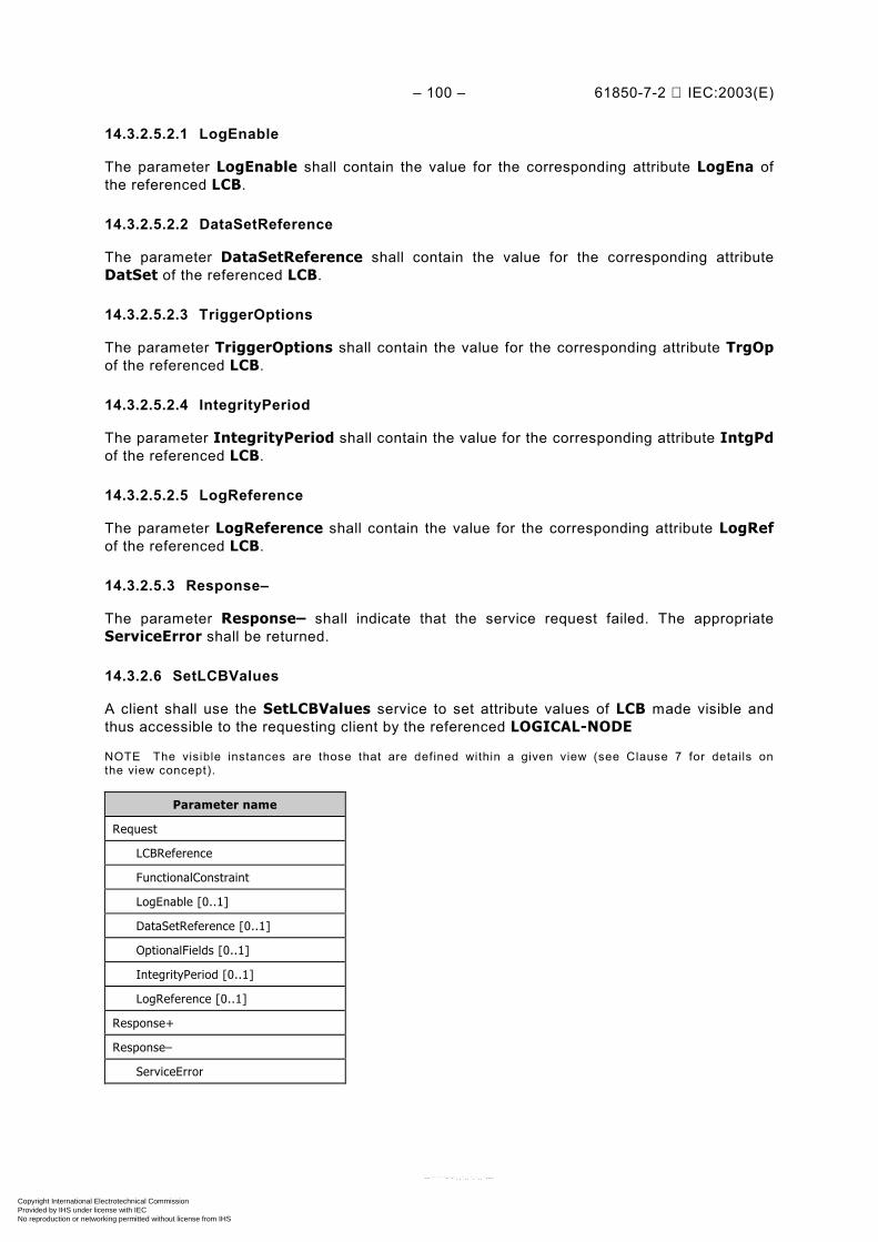
– 100 – 61850-7-2 IEC:2003(E)
14.3.2.5.2.1 LogEnable
The parameter LogEnable shall contain the value for the corresponding attribute LogEna ofthe referenced LCB.
14.3.2.5.2.2 DataSetReference
The parameter DataSetReference shall contain the value for the corresponding attributeDatSet of the referenced LCB.
14.3.2.5.2.3 TriggerOptions
The parameter TriggerOptions shall contain the value for the corresponding attribute TrgOpof the referenced LCB.
14.3.2.5.2.4 IntegrityPeriod
The parameter IntegrityPeriod shall contain the value for the corresponding attribute IntgPdof the referenced LCB.
14.3.2.5.2.5 LogReference
The parameter LogReference shall contain the value for the corresponding attribute LogRefof the referenced LCB.
14.3.2.5.3 Response–
The parameter Response– shall indicate that the service request failed. The appropriateServiceError shall be returned.
14.3.2.6 SetLCBValues
A client shall use the SetLCBValues service to set attribute values of LCB made visible andthus accessible to the requesting client by the referenced LOGICAL-NODE
NOTE The visible instances are those that are defined within a given view (see Clause 7 for details onthe view concept).
Parameter name
Request
LCBReference
FunctionalConstraint
LogEnable [0..1]
DataSetReference [0..1]
OptionalFields [0..1]
IntegrityPeriod [0..1]
LogReference [0..1]
Response+
Response–
ServiceError
Copyright International Electrotechnical Commission Provided by IHS under license with IEC
Not for ResaleNo reproduction or networking permitted without license from IHS
--``````-`-`,,`,,`,`,,`---
61850-7-2 © IEC:2003(E) – 101 –
14.3.2.6.1 Request
14.3.2.6.1.1 LCBReference
The parameter LCBReference shall specify the ObjectReference of LCB.
The service parameter LCBReference shall be LCBRef.
14.3.2.6.1.2 FunctionalConstraint
The parameter FunctionalConstraint shall contain the value of the functional constraintparameter to filter the respective instances of attributes of a LCB.
The service parameter FunctionalConstraint shall be LG (logging).
14.3.2.6.1.3 LogEnable [0..1]
The parameter LogEnable shall contain the value of the corresponding attribute LogEna of thereferenced LCB.
14.3.2.6.1.4 DataSetReference [0..1]
The parameter DataSetReference shall contain the value of the corresponding attributeDatSet of the referenced LCB.
14.3.2.6.1.5 OptionalFields [0..1]
The parameter OptionalFields shall contain the value of the corresponding attribute TrgOp ofthe referenced LCB.
14.3.2.6.1.6 IntegrityPeriod [0..1]
The parameter IntegrityPeriod shall contain the value of the corresponding attribute IntgPdof the referenced LCB.
14.3.2.6.1.7 LogReference [0..1]
The parameter LogReference shall contain the value of the corresponding attribute LogRef ofthe referenced LCB.
14.3.2.6.2 Response+
The parameter Response+ shall indicate that the service request succeeded.
14.3.2.6.3 Response–
The parameter Response– shall indicate that the service request failed. The appropriateServiceError shall be returned.
This service shall return a failure if the service has been issued for any attribute of a LCB otherthan enable while LCB is enabled.
14.3.3 LOG class definition
14.3.3.1 LOG class syntax
The LOG shall be filled on a first-in first-out basis. When the list of log entries reaches a pointwhere the stored data reaches the maximal size of the log, the oldest log entry shall be
Copyright International Electrotechnical Commission Provided by IHS under license with IEC
Not for ResaleNo reproduction or networking permitted without license from IHS
--``````-`-`,,`,,`,`,,`---
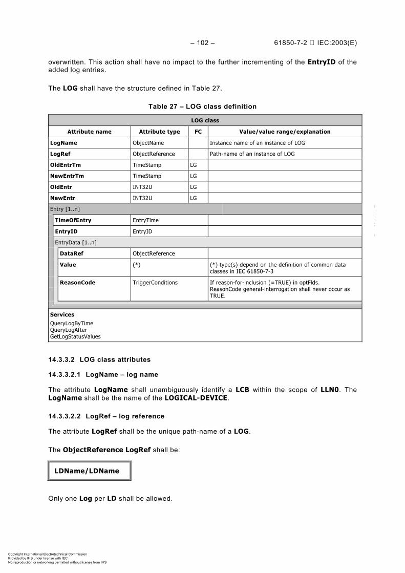
– 102 – 61850-7-2 IEC:2003(E)
overwritten. This action shall have no impact to the further incrementing of the EntryID of theadded log entries.
The LOG shall have the structure defined in Table 27.
Table 27 – LOG class definition
LOG class
Attribute name Attribute type FC Value/value range/explanation
LogName ObjectName Instance name of an instance of LOG
LogRef ObjectReference Path-name of an instance of LOG
OldEntrTm TimeStamp LG
NewEntrTm TimeStamp LG
OldEntr INT32U LG
NewEntr INT32U LG
Entry [1..n]
TimeOfEntry EntryTime
EntryID EntryID
EntryData [1..n]
DataRef ObjectReference
Value (*) (*) type(s) depend on the definition of common dataclasses in IEC 61850-7-3
ReasonCode TriggerConditions If reason-for-inclusion (=TRUE) in optFlds.ReasonCode general-interrogation shall never occur asTRUE.
ServicesQueryLogByTimeQueryLogAfterGetLogStatusValues
14.3.3.2 LOG class attributes
14.3.3.2.1 LogName – log name
The attribute LogName shall unambiguously identify a LCB within the scope of LLN0. TheLogName shall be the name of the LOGICAL-DEVICE.
14.3.3.2.2 LogRef – log reference
The attribute LogRef shall be the unique path-name of a LOG.
The ObjectReference LogRef shall be:
LDName/LDName
Only one Log per LD shall be allowed.
Copyright International Electrotechnical Commission Provided by IHS under license with IEC
Not for ResaleNo reproduction or networking permitted without license from IHS
--``````-`-`,,`,,`,`,,`---
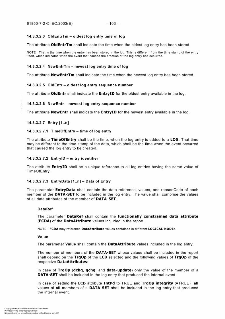
61850-7-2 © IEC:2003(E) – 103 –
14.3.3.2.3 OldEntrTm – oldest log entry time of log
The attribute OldEntrTm shall indicate the time when the oldest log entry has been stored.
NOTE That is the time when the entry has been stored in the log. This is different from the time stamp of the entryitself, which indicates when the event that caused the creation of the log entry has occurred.
14.3.3.2.4 NewEntrTm – newest log entry time of log
The attribute NewEntrTm shall indicate the time when the newest log entry has been stored.
14.3.3.2.5 OldEntr – oldest log entry sequence number
The attribute OldEntr shall indicate the EntryID for the oldest entry available in the log.
14.3.3.2.6 NewEntr – newest log entry sequence number
The attribute NewEntr shall indicate the EntryID for the newest entry available in the log.
14.3.3.2.7 Entry [1..n]
14.3.3.2.7.1 TimeOfEntry – time of log entry
The attribute TimeOfEntry shall be the time, when the log entry is added to a LOG. That timemay be different to the time stamp of the data, which shall be the time when the event occurredthat caused the log entry to be created.
14.3.3.2.7.2 EntryID – entry identifier
The attribute EntryID shall be a unique reference to all log entries having the same value ofTimeOfEntry.
14.3.3.2.7.3 EntryData [1..n] – Data of Entry
The parameter EntryData shall contain the data reference, values, and reasonCode of eachmember of the DATA-SET to be included in the log entry. The value shall comprise the valuesof all data attributes of the member of DATA-SET.
DataRef
The parameter DataRef shall contain the functionally constrained data attribute(FCDA) of the DataAttribute values included in the report.
NOTE FCDA may reference DataAttribute values contained in different LOGICAL-NODEs.
Value
The parameter Value shall contain the DataAttribute values included in the log entry.
The number of members of the DATA-SET whose values shall be included in the reportshall depend on the TrgOp of the LCB selected and the following values of TrgOp of therespective DataAttributes:
In case of TrgOp (dchg, qchg, and data-update) only the value of the member of aDATA-SET shall be included in the log entry that produced the internal event.
In case of setting the LCB attribute IntPd to TRUE and TrgOp integrity (=TRUE) allvalues of all members of a DATA-SET shall be included in the log entry that producedthe internal event.
Copyright International Electrotechnical Commission Provided by IHS under license with IEC
Not for ResaleNo reproduction or networking permitted without license from IHS
--``````-`-`,,`,,`,`,,`---

– 104 – 61850-7-2 IEC:2003(E)
ReasonCode – reason for inclusion
The reason for inclusion shall be set according the TrgOp that caused the creation of theEntryData. The value for reason for inclusion shall be set according the TrgOp thatcaused the creation of the report. The value range for reasons for inclusion shall beas listed:– data-change (caused by TrgOp = dchg in an instance of DATA)– quality-change (caused by TrgOp = qchg in an instance of DATA)– data-update (caused by TrgOp = dupd in an instance of DATA)– integrity (caused by the attribute IntgPd in the LCB)
14.3.4 Procedures to generate the log entries
14.3.4.1 OverviewBasically, the conditions and constraints for log generation shall be the same as for reportgeneration (see 14.2.3.2.3). Subclause 14.3.4 specifies the differences only.
14.3.4.2 Trigger Options data-change, quality-change, or data-update
When the LCB is notified by an internal event of a data-change, a quality-change, a data-update of the referenced member of a DATA-SET, the LCB shall create a LOG entry with thevalue of the member of DATA-SET that produced the internal event.
14.3.4.3 Trigger options integrity
When a LCB is notified as a result of the trigger options integrity, the LCB shall create a LOGentry for each member of the referenced DATA-SET.
14.3.5 LOG services
14.3.5.1 Overview
For the LOG model, the following services are defined:
Service Description
QueryLogByTime Read the log entries selected by time
QueryLogAfter Read the log entries selected by entryID
GetLogStatusValues Get the status values of a LOG
14.3.5.2 QueryLogByTime
14.3.5.2.1 QueryLogByTime parameter table
A client shall use the QueryLogByTime service to retrieve a range of LOG entries from a LOGbased on time ranges (RangeStartTime and RangeStopTime).
Parameter name
Request
LogReference
RangeStartTime
RangeStopTime
Response+
ListOfLogEntries
Response–
ServiceError
Copyright International Electrotechnical Commission Provided by IHS under license with IEC
Not for ResaleNo reproduction or networking permitted without license from IHS
--``````-`-`,,`,,`,`,,`---
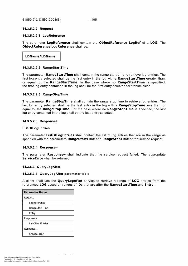
61850-7-2 © IEC:2003(E) – 105 –
14.3.5.2.2 Request
14.3.5.2.2.1 LogReference
The parameter LogReference shall contain the ObjectReference LogRef of a LOG. TheObjectReference LogReference shall be:
LDName/LDName
14.3.5.2.2.2 RangeStartTime
The parameter RangeStartTime shall contain the range start time to retrieve log entries. Thefirst log entry selected shall be the first entry in the log with a RangeStartTime greater than,or equal to, the RangeStartTime. In the case where no RangeStartTime is specified,the first log entry contained in the log shall be the first entry selected for transmission.
14.3.5.2.2.3 RangeStopTime
The parameter RangeStopTime shall contain the range stop time to retrieve log entries. Thelast log entry selected shall be the last entry in the log with a RangeStopTime less than, orequal to, the RangeStopTime. For the case where no RangeStopTime is specified, the lastlog entry contained in the log shall be the last entry selected.
14.3.5.2.3 Response+
ListOfLogEntries
The parameter ListOfLogEntries shall contain the list of log entries that are in the range asspecified with the parameters RangeStartTime and RangeStopTime of the service request.
14.3.5.2.4 Response–
The parameter Response– shall indicate that the service request failed. The appropriateServiceError shall be returned.
14.3.5.3 QueryLogAfter
14.3.5.3.1 QueryLogAfter parameter table
A client shall use the QueryLogAfter service to retrieve a range of LOG entries from thereferenced LOG based on ranges of IDs that are after the RangeStartTime and Entry.
Parameter Name
Request
LogReference
RangeStartTime
Entry
Response+
ListOfLogEntries
Response–
ServiceError
Copyright International Electrotechnical Commission Provided by IHS under license with IEC
Not for ResaleNo reproduction or networking permitted without license from IHS
--``````-`-`,,`,,`,`,,`---

– 106 – 61850-7-2 IEC:2003(E)
14.3.5.3.2 Request
14.3.5.3.2.1 LogReference
The parameter LogReference shall specify the ObjectReference LogRef of the LOG. TheObjectReference LogReference shall be:
LDName/LDName
14.3.5.3.2.2 RangeStartTime
The parameter RangeStartTime shall contain the time of the log entry (or log entries – incase of multiple entries for a single time stamp) selected.
14.3.5.3.2.3 Entry
The parameter Entry shall reference the LOG entry of the selected RangeStartTime afterwhich the log entries shall be selected.
14.3.5.3.3 Response+
14.3.5.3.3.1 ListOfLogEntries
The parameter ListOfLogEntries shall contain the list of log entries that follow after theentries as specified with the parameters RangeStartTime and Entry of the service request.
14.3.5.3.4 Response–
The parameter Response– shall indicate that the service request failed. The appropriateServiceError shall be returned.
14.3.5.4 GetLogStatusValues
A client shall use the GetLCBValues service to retrieve the attribute values of a LOG madevisible and thus accessible to the requesting client by the referenced LLN0.
NOTE The visible instances are those that are defined within a given view (see Clause 7 for details on theview concept).
Parameter name
Request
LogReference
FunctionalConstraint
Response+
OldestEntryTime
NewestEntryTime
OldestEntry
NewestEntry
Response–
ServiceError
Copyright International Electrotechnical Commission Provided by IHS under license with IEC
Not for ResaleNo reproduction or networking permitted without license from IHS
--``````-`-`,,`,,`,`,,`---
61850-7-2 © IEC:2003(E) – 107 –
14.3.5.4.1 Request
14.3.5.4.1.1 LogReference
The parameter LogReference shall specify the ObjectReference of the LOG.
The service parameter LogReference shall be:
LDName/LDName
14.3.5.4.1.2 FunctionalConstraint
The parameter FunctionalConstraint shall contain the value of the functional constraintparameter to filter the respective instances of attributes of a LOG.
The service parameter FunctionalConstraint shall be LG (logging).
14.3.5.4.2 Response+
The parameter Response+ shall indicate that the service request succeeded.
14.3.5.4.2.1 OldestEntryTime
The parameter OldestEntryTime shall contain the value for the corresponding attributeOldEntrTm of the referenced LOG.
14.3.5.4.2.2 NewestEntryTime
The parameter NewestEntryTime shall contain the value for the corresponding attributeNewEntrTm of the referenced LOG.
14.3.5.4.2.3 OldestEntry
The parameter OldestEntry shall contain the value for the corresponding attribute OldEntr ofthe referenced LOG.
14.3.5.4.2.4 NewestEntry
The parameter NewestEntry shall contain the value for the corresponding attribute NewEntrof the referenced LOG.
14.3.5.4.3 Response–
The parameter Response– shall indicate that the service request failed. The appropriateServiceError shall be returned.
15 Generic substation event class model (GSE)
15.1 Overview
The generic substation event model provides the possibility for a fast and reliable system-widedistribution of input and output data values. The generic substation event model is based onthe concept of an autonomous decentralization, providing an efficient method allowing thesimultaneous delivery of the same generic substation event information to more than onephysical device through the use of multicast/broadcast services.
Copyright International Electrotechnical Commission Provided by IHS under license with IEC
Not for ResaleNo reproduction or networking permitted without license from IHS
--``````-`-`,,`,,`,`,,`---
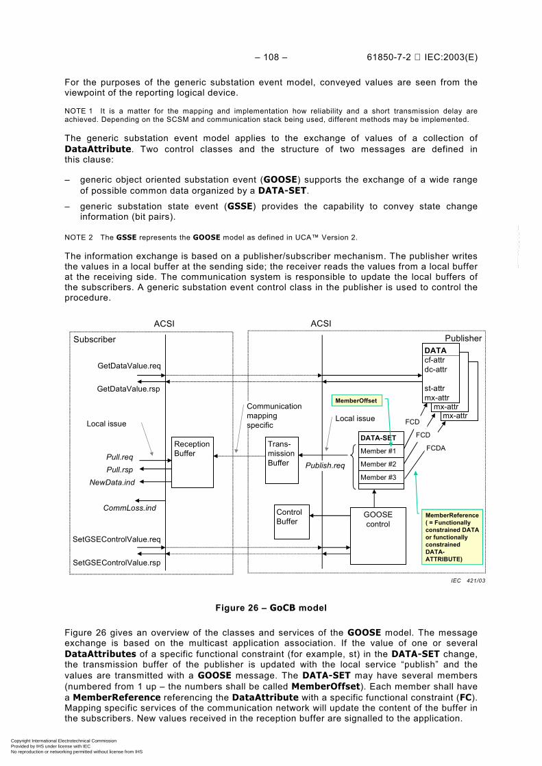
– 108 – 61850-7-2 IEC:2003(E)
For the purposes of the generic substation event model, conveyed values are seen from theviewpoint of the reporting logical device.
NOTE 1 It is a matter for the mapping and implementation how reliability and a short transmission delay areachieved. Depending on the SCSM and communication stack being used, different methods may be implemented.
The generic substation event model applies to the exchange of values of a collection ofDataAttribute. Two control classes and the structure of two messages are defined inthis clause:
– generic object oriented substation event (GOOSE) supports the exchange of a wide rangeof possible common data organized by a DATA-SET.
– generic substation state event (GSSE) provides the capability to convey state changeinformation (bit pairs).
NOTE 2 The GSSE represents the GOOSE model as defined in UCA™ Version 2.
The information exchange is based on a publisher/subscriber mechanism. The publisher writesthe values in a local buffer at the sending side; the receiver reads the values from a local bufferat the receiving side. The communication system is responsible to update the local buffers ofthe subscribers. A generic substation event control class in the publisher is used to control theprocedure.
DOcf-attrdc-attr
st-attrmx-attr
DOcf-attrdc-attr
st-attrmx-attr
PublisherSubscriber
ACSI ACSI
GOOSEcontrol
DATAcf-attrdc-attr
st-attrmx-attr
Trans-missionBuffer
ControlBuffer
ReceptionBuffer
GetDataValue.req
GetDataValue.rsp
Publish.reqPull.reqPull.rsp
NewData.ind
SetGSEControlValue.req
SetGSEControlValue.rsp
Local issue
DATA-SET
Local issueCommunicationmappingspecific
CommLoss.ind
Member #1
Member #2
Member #3
FCD
FCD
FCDA
MemberReference( = Functionallyconstrained DATAor functionallyconstrainedDATA-ATTRIBUTE)
MemberOffset
Figure 26 – GoCB model
Figure 26 gives an overview of the classes and services of the GOOSE model. The messageexchange is based on the multicast application association. If the value of one or severalDataAttributes of a specific functional constraint (for example, st) in the DATA-SET change,the transmission buffer of the publisher is updated with the local service “publish” and thevalues are transmitted with a GOOSE message. The DATA-SET may have several members(numbered from 1 up – the numbers shall be called MemberOffset). Each member shall havea MemberReference referencing the DataAttribute with a specific functional constraint (FC).Mapping specific services of the communication network will update the content of the buffer inthe subscribers. New values received in the reception buffer are signalled to the application.
IEC 421/03
Copyright International Electrotechnical Commission Provided by IHS under license with IEC
Not for ResaleNo reproduction or networking permitted without license from IHS
--``````-`-`,,`,,`,`,,`---
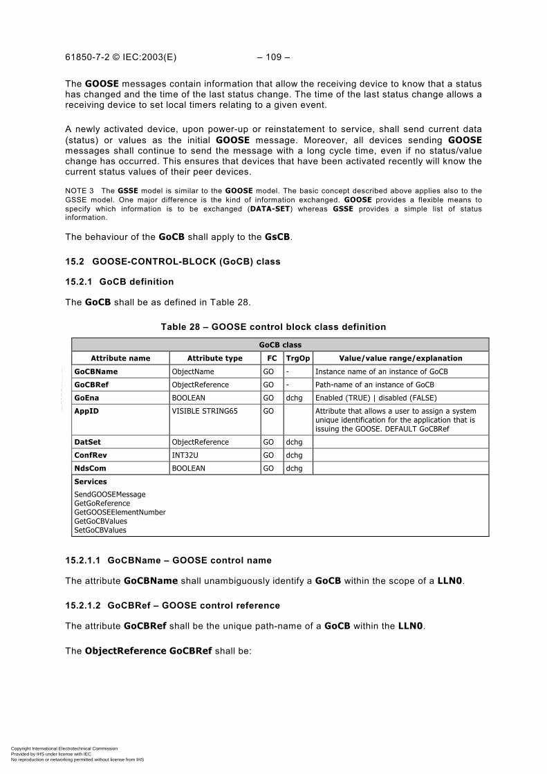
61850-7-2 © IEC:2003(E) – 109 –
The GOOSE messages contain information that allow the receiving device to know that a statushas changed and the time of the last status change. The time of the last status change allows areceiving device to set local timers relating to a given event.
A newly activated device, upon power-up or reinstatement to service, shall send current data(status) or values as the initial GOOSE message. Moreover, all devices sending GOOSEmessages shall continue to send the message with a long cycle time, even if no status/valuechange has occurred. This ensures that devices that have been activated recently will know thecurrent status values of their peer devices.
NOTE 3 The GSSE model is similar to the GOOSE model. The basic concept described above applies also to theGSSE model. One major difference is the kind of information exchanged. GOOSE provides a flexible means tospecify which information is to be exchanged (DATA-SET) whereas GSSE provides a simple list of statusinformation.
The behaviour of the GoCB shall apply to the GsCB.
15.2 GOOSE-CONTROL-BLOCK (GoCB) class
15.2.1 GoCB definition
The GoCB shall be as defined in Table 28.
Table 28 – GOOSE control block class definition
GoCB class
Attribute name Attribute type FC TrgOp Value/value range/explanation
GoCBName ObjectName GO - Instance name of an instance of GoCB
GoCBRef ObjectReference GO - Path-name of an instance of GoCB
GoEna BOOLEAN GO dchg Enabled (TRUE) | disabled (FALSE)
AppID VISIBLE STRING65 GO Attribute that allows a user to assign a systemunique identification for the application that isissuing the GOOSE. DEFAULT GoCBRef
DatSet ObjectReference GO dchg
ConfRev INT32U GO dchg
NdsCom BOOLEAN GO dchg
Services
SendGOOSEMessageGetGoReferenceGetGOOSEElementNumberGetGoCBValuesSetGoCBValues
15.2.1.1 GoCBName – GOOSE control name
The attribute GoCBName shall unambiguously identify a GoCB within the scope of a LLN0.
15.2.1.2 GoCBRef – GOOSE control reference
The attribute GoCBRef shall be the unique path-name of a GoCB within the LLN0.
The ObjectReference GoCBRef shall be:
Copyright International Electrotechnical Commission Provided by IHS under license with IEC
Not for ResaleNo reproduction or networking permitted without license from IHS
--``````-`-`,,`,,`,`,,`---
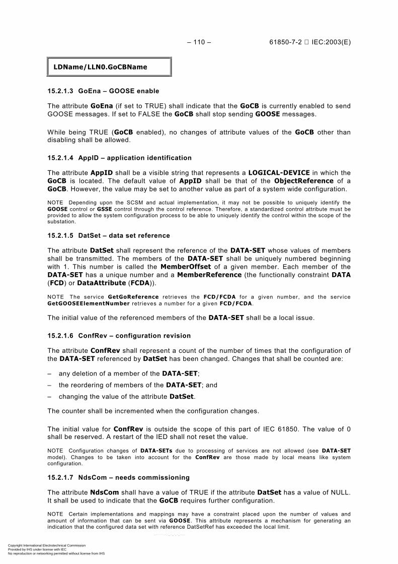
– 110 – 61850-7-2 IEC:2003(E)
LDName/LLN0.GoCBName
15.2.1.3 GoEna – GOOSE enable
The attribute GoEna (if set to TRUE) shall indicate that the GoCB is currently enabled to sendGOOSE messages. If set to FALSE the GoCB shall stop sending GOOSE messages.
While being TRUE (GoCB enabled), no changes of attribute values of the GoCB other thandisabling shall be allowed.
15.2.1.4 AppID – application identification
The attribute AppID shall be a visible string that represents a LOGICAL-DEVICE in which theGoCB is located. The default value of AppID shall be that of the ObjectReference of aGoCB. However, the value may be set to another value as part of a system wide configuration.
NOTE Depending upon the SCSM and actual implementation, it may not be possible to uniquely identify theGOOSE control or GSSE control through the control reference. Therefore, a standardized control attribute must beprovided to allow the system configuration process to be able to uniquely identify the control within the scope of thesubstation.
15.2.1.5 DatSet – data set reference
The attribute DatSet shall represent the reference of the DATA-SET whose values of membersshall be transmitted. The members of the DATA-SET shall be uniquely numbered beginningwith 1. This number is called the MemberOffset of a given member. Each member of theDATA-SET has a unique number and a MemberReference (the functionally constraint DATA(FCD) or DataAttribute (FCDA)).
NOTE The service GetGoReference retr ieves the FCD/FCDA for a given number, and the serviceGetGOOSEElementNumber retr ieves a number for a given FCD/FCDA .
The initial value of the referenced members of the DATA-SET shall be a local issue.
15.2.1.6 ConfRev – configuration revision
The attribute ConfRev shall represent a count of the number of times that the configuration ofthe DATA-SET referenced by DatSet has been changed. Changes that shall be counted are:
– any deletion of a member of the DATA-SET;
– the reordering of members of the DATA-SET; and
– changing the value of the attribute DatSet.
The counter shall be incremented when the configuration changes.
The initial value for ConfRev is outside the scope of this part of IEC 61850. The value of 0shall be reserved. A restart of the IED shall not reset the value.
NOTE Configuration changes of DATA-SETs due to processing of services are not allowed (see DATA-SETmodel). Changes to be taken into account for the ConfRev are those made by local means like systemconfiguration.
15.2.1.7 NdsCom – needs commissioning
The attribute NdsCom shall have a value of TRUE if the attribute DatSet has a value of NULL.It shall be used to indicate that the GoCB requires further configuration.
NOTE Certain implementations and mappings may have a constraint placed upon the number of values andamount of information that can be sent via GOOSE . This attribute represents a mechanism for generating anindication that the configured data set with reference DatSetRef has exceeded the local limit.
Copyright International Electrotechnical Commission Provided by IHS under license with IEC
Not for ResaleNo reproduction or networking permitted without license from IHS
--``````-`-`,,`,,`,`,,`---
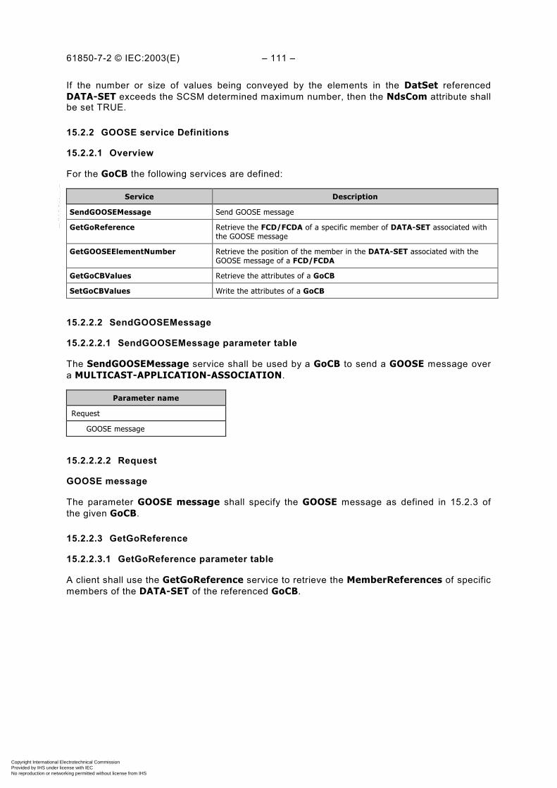
61850-7-2 © IEC:2003(E) – 111 –
If the number or size of values being conveyed by the elements in the DatSet referencedDATA-SET exceeds the SCSM determined maximum number, then the NdsCom attribute shallbe set TRUE.
15.2.2 GOOSE service Definitions
15.2.2.1 Overview
For the GoCB the following services are defined:
Service Description
SendGOOSEMessage Send GOOSE message
GetGoReference Retrieve the FCD/FCDA of a specific member of DATA-SET associated withthe GOOSE message
GetGOOSEElementNumber Retrieve the position of the member in the DATA-SET associated with theGOOSE message of a FCD/FCDA
GetGoCBValues Retrieve the attributes of a GoCB
SetGoCBValues Write the attributes of a GoCB
15.2.2.2 SendGOOSEMessage
15.2.2.2.1 SendGOOSEMessage parameter table
The SendGOOSEMessage service shall be used by a GoCB to send a GOOSE message overa MULTICAST-APPLICATION-ASSOCIATION.
Parameter name
Request
GOOSE message
15.2.2.2.2 Request
GOOSE message
The parameter GOOSE message shall specify the GOOSE message as defined in 15.2.3 ofthe given GoCB.
15.2.2.3 GetGoReference
15.2.2.3.1 GetGoReference parameter table
A client shall use the GetGoReference service to retrieve the MemberReferences of specificmembers of the DATA-SET of the referenced GoCB.
Copyright International Electrotechnical Commission Provided by IHS under license with IEC
Not for ResaleNo reproduction or networking permitted without license from IHS
--``````-`-`,,`,,`,`,,`---
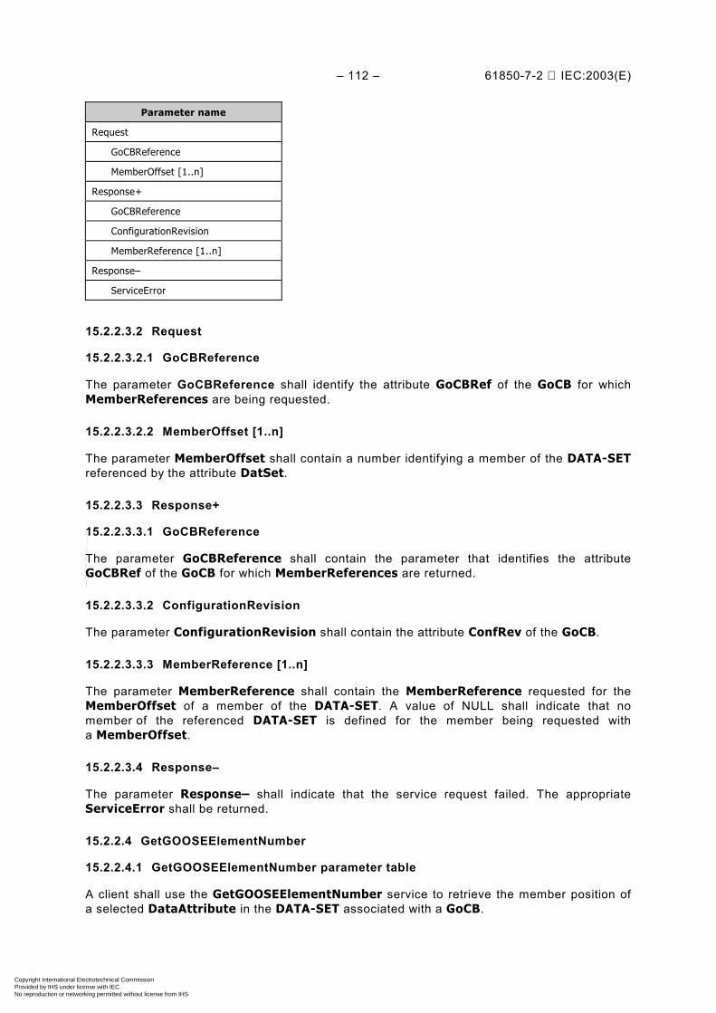
– 112 – 61850-7-2 IEC:2003(E)
Parameter name
Request
GoCBReference
MemberOffset [1..n]
Response+
GoCBReference
ConfigurationRevision
MemberReference [1..n]
Response–
ServiceError
15.2.2.3.2 Request
15.2.2.3.2.1 GoCBReference
The parameter GoCBReference shall identify the attribute GoCBRef of the GoCB for whichMemberReferences are being requested.
15.2.2.3.2.2 MemberOffset [1..n]
The parameter MemberOffset shall contain a number identifying a member of the DATA-SETreferenced by the attribute DatSet.
15.2.2.3.3 Response+
15.2.2.3.3.1 GoCBReference
The parameter GoCBReference shall contain the parameter that identifies the attributeGoCBRef of the GoCB for which MemberReferences are returned.
15.2.2.3.3.2 ConfigurationRevision
The parameter ConfigurationRevision shall contain the attribute ConfRev of the GoCB.
15.2.2.3.3.3 MemberReference [1..n]
The parameter MemberReference shall contain the MemberReference requested for theMemberOffset of a member of the DATA-SET. A value of NULL shall indicate that nomember of the referenced DATA-SET is defined for the member being requested witha MemberOffset.
15.2.2.3.4 Response–
The parameter Response– shall indicate that the service request failed. The appropriateServiceError shall be returned.
15.2.2.4 GetGOOSEElementNumber
15.2.2.4.1 GetGOOSEElementNumber parameter table
A client shall use the GetGOOSEElementNumber service to retrieve the member position ofa selected DataAttribute in the DATA-SET associated with a GoCB.
Copyright International Electrotechnical Commission Provided by IHS under license with IEC
Not for ResaleNo reproduction or networking permitted without license from IHS
--``````-`-`,,`,,`,`,,`---
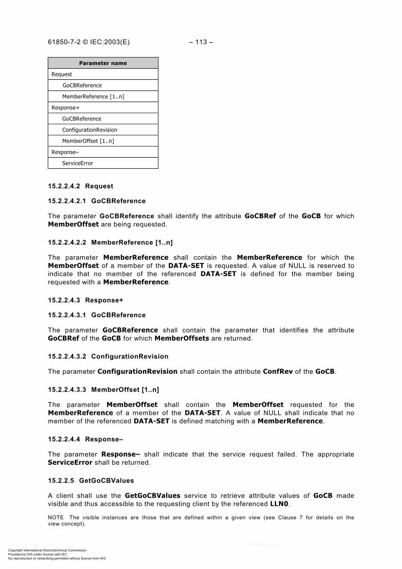
61850-7-2 © IEC:2003(E) – 113 –
Parameter name
Request
GoCBReference
MemberReference [1..n]
Response+
GoCBReference
ConfigurationRevision
MemberOffset [1..n]
Response–
ServiceError
15.2.2.4.2 Request
15.2.2.4.2.1 GoCBReference
The parameter GoCBReference shall identify the attribute GoCBRef of the GoCB for whichMemberOffset are being requested.
15.2.2.4.2.2 MemberReference [1..n]
The parameter MemberReference shall contain the MemberReference for which theMemberOffset of a member of the DATA-SET is requested. A value of NULL is reserved toindicate that no member of the referenced DATA-SET is defined for the member beingrequested with a MemberReference.
15.2.2.4.3 Response+
15.2.2.4.3.1 GoCBReference
The parameter GoCBReference shall contain the parameter that identifies the attributeGoCBRef of the GoCB for which MemberOffsets are returned.
15.2.2.4.3.2 ConfigurationRevision
The parameter ConfigurationRevision shall contain the attribute ConfRev of the GoCB.
15.2.2.4.3.3 MemberOffset [1..n]
The parameter MemberOffset shall contain the MemberOffset requested for theMemberReference of a member of the DATA-SET. A value of NULL shall indicate that nomember of the referenced DATA-SET is defined matching with a MemberReference.
15.2.2.4.4 Response–
The parameter Response– shall indicate that the service request failed. The appropriateServiceError shall be returned.
15.2.2.5 GetGoCBValues
A client shall use the GetGoCBValues service to retrieve attribute values of GoCB madevisible and thus accessible to the requesting client by the referenced LLN0.
NOTE The visible instances are those that are defined within a given view (see Clause 7 for details on theview concept).
Copyright International Electrotechnical Commission Provided by IHS under license with IEC
Not for ResaleNo reproduction or networking permitted without license from IHS
--``````-`-`,,`,,`,`,,`---
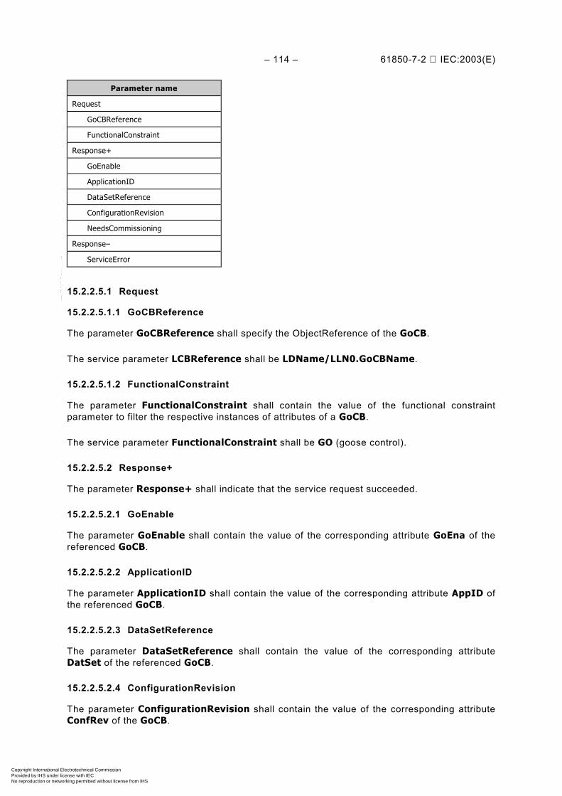
– 114 – 61850-7-2 IEC:2003(E)
Parameter name
Request
GoCBReference
FunctionalConstraint
Response+
GoEnable
ApplicationID
DataSetReference
ConfigurationRevision
NeedsCommissioning
Response–
ServiceError
15.2.2.5.1 Request
15.2.2.5.1.1 GoCBReference
The parameter GoCBReference shall specify the ObjectReference of the GoCB.
The service parameter LCBReference shall be LDName/LLN0.GoCBName.
15.2.2.5.1.2 FunctionalConstraint
The parameter FunctionalConstraint shall contain the value of the functional constraintparameter to filter the respective instances of attributes of a GoCB.
The service parameter FunctionalConstraint shall be GO (goose control).
15.2.2.5.2 Response+
The parameter Response+ shall indicate that the service request succeeded.
15.2.2.5.2.1 GoEnable
The parameter GoEnable shall contain the value of the corresponding attribute GoEna of thereferenced GoCB.
15.2.2.5.2.2 ApplicationID
The parameter ApplicationID shall contain the value of the corresponding attribute AppID ofthe referenced GoCB.
15.2.2.5.2.3 DataSetReference
The parameter DataSetReference shall contain the value of the corresponding attributeDatSet of the referenced GoCB.
15.2.2.5.2.4 ConfigurationRevision
The parameter ConfigurationRevision shall contain the value of the corresponding attributeConfRev of the GoCB.
Copyright International Electrotechnical Commission Provided by IHS under license with IEC
Not for ResaleNo reproduction or networking permitted without license from IHS
--``````-`-`,,`,,`,`,,`---
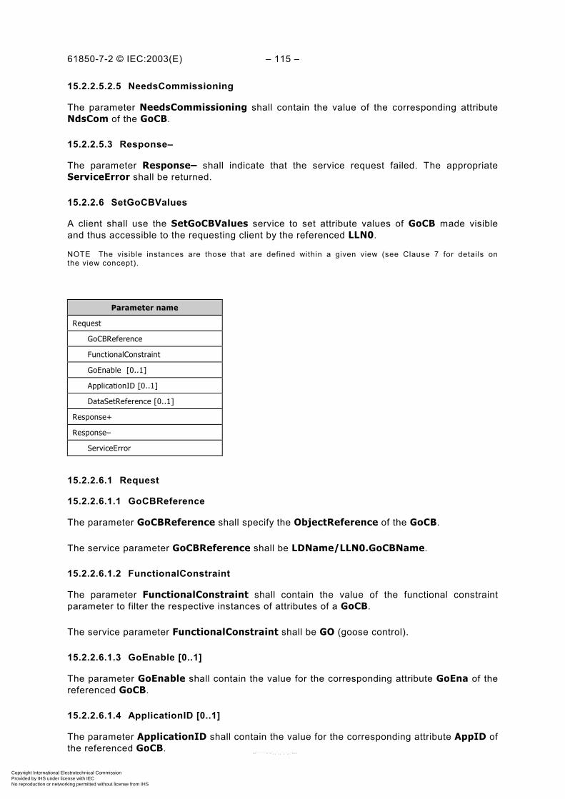
61850-7-2 © IEC:2003(E) – 115 –
15.2.2.5.2.5 NeedsCommissioning
The parameter NeedsCommissioning shall contain the value of the corresponding attributeNdsCom of the GoCB.
15.2.2.5.3 Response–
The parameter Response– shall indicate that the service request failed. The appropriateServiceError shall be returned.
15.2.2.6 SetGoCBValues
A client shall use the SetGoCBValues service to set attribute values of GoCB made visibleand thus accessible to the requesting client by the referenced LLN0.
NOTE The visible instances are those that are defined within a given view (see Clause 7 for details onthe view concept).
Parameter name
Request
GoCBReference
FunctionalConstraint
GoEnable [0..1]
ApplicationID [0..1]
DataSetReference [0..1]
Response+
Response–
ServiceError
15.2.2.6.1 Request
15.2.2.6.1.1 GoCBReference
The parameter GoCBReference shall specify the ObjectReference of the GoCB.
The service parameter GoCBReference shall be LDName/LLN0.GoCBName.
15.2.2.6.1.2 FunctionalConstraint
The parameter FunctionalConstraint shall contain the value of the functional constraintparameter to filter the respective instances of attributes of a GoCB.
The service parameter FunctionalConstraint shall be GO (goose control).
15.2.2.6.1.3 GoEnable [0..1]
The parameter GoEnable shall contain the value for the corresponding attribute GoEna of thereferenced GoCB.
15.2.2.6.1.4 ApplicationID [0..1]
The parameter ApplicationID shall contain the value for the corresponding attribute AppID ofthe referenced GoCB.
Copyright International Electrotechnical Commission Provided by IHS under license with IEC
Not for ResaleNo reproduction or networking permitted without license from IHS
--``````-`-`,,`,,`,`,,`---

– 116 – 61850-7-2 IEC:2003(E)
15.2.2.6.1.5 DataSetReference [0..1]
The parameter DataSetReference shall contain the value for the corresponding attributeDatSet of the referenced GoCB.
15.2.2.6.2 Response+
The parameter Response+ shall indicate that the service request succeeded.
15.2.2.6.3 Response–
The parameter Response– shall indicate that the service request failed. The appropriateServiceError shall be returned.
This service shall return a failure if the service has been issued for any attribute of a GoCBother than GoEnable while GoCB is enabled.
15.2.3 Generic object oriented substation event (GOOSE) message
15.2.3.1 GOOSE message syntax
The abstract GOOSE message format shall specify the information to be included in theGOOSE message. The structure of the GOOSE message shall be as specified in Table 29.
A GOOSE message shall at least be sent each time when a value from one or more membersreferenced by the DATA-SET change.
Table 29 – GOOSE message definition
GOOSE message
Parameter name Parameter type Value/value range/explanation
DatSet ObjectReference Value from the instance of GoCB
AppID VISIBLE STRING65 Value from the instance of GoCB
GoCBRef ObjectReference Value from the instance of GoCB
T EntryTime
StNum INT32U
SqNum INT32U
Test BOOLEAN (TRUE) test | (FALSE) no-test
ConfRev INT32U Value from the instance of GoCB
NdsCom BOOLEAN Value from the instance of GoCB
GOOSEData [1..n]
Value (*) (*) type depends on the common data classes definedin IEC 61850-7-3. The parameter shall be derivedfrom GOOSE control
15.2.3.2 DatSet – data setThe parameter DatSet shall contain the ObjectReference of the DATA-SET (taken from theGoCB) whose values of the members shall be transmitted.
15.2.3.3 AppID – application identifier
The parameter AppID shall contain the identifier of the LOGICAL-DEVICE (taken from theGoCB) in which the GoCB is located.
Copyright International Electrotechnical Commission Provided by IHS under license with IEC
Not for ResaleNo reproduction or networking permitted without license from IHS
--``````-`-`,,`,,`,`,,`---
61850-7-2 © IEC:2003(E) – 117 –
15.2.3.4 GoCBRef – GOOSE control block reference
The parameter GoCBRef shall contain the reference of the GOOSE control block.
15.2.3.5 T – time stamp
The parameter T shall contain the time at which the attribute StNum was incremented.
15.2.3.6 StNum – state number
The parameter StNum shall contain the counter that increments each time a GOOSE messagehas been sent and a value change has been detected within the DATA-SET specified byDatSet.
The initial value for StNum shall be 1. The value of 0 shall be reserved.
15.2.3.7 SqNum – sequence number
The parameter SqNum shall contain the counter that shall increment each time a GOOSEmessage has been sent.
The initial value for SqNum shall be 1. The value of 0 shall be reserved.
15.2.3.8 Test – test
The parameter Test shall indicate with the value of TRUE that the values of the message shallnot be used for operational purposes.
15.2.3.9 ConfRev – configuration revision
The parameter ConfRev (taken from the GoCB) shall contain the count of the number of timesthat the configuration of the DATA-SET referenced by DatSet has been changed.
15.2.3.10 NdsCom – needs commissioning
The parameter NdsCom shall contain the attribute NdsCom (taken from the GoCB) of theGoCB.
15.2.3.11 GOOSEData [1..n]
The parameter GOOSEData shall contain the user-defined information (of the members ofDATA-SET) to be included in a GOOSE message.
The parameter Value shall contain the value of a member of the DATA-SET referenced in theGoCB.
15.3 Generic substation state event (GSSE) control block (GsCB)
15.3.1 GsCB class definition
The specifics for the GsCB model (compared to the GoCB model) is depicted in the shadowedarea in Figure 27.
Copyright International Electrotechnical Commission Provided by IHS under license with IEC
Not for ResaleNo reproduction or networking permitted without license from IHS
--``````-`-`,,`,,`,`,,`---
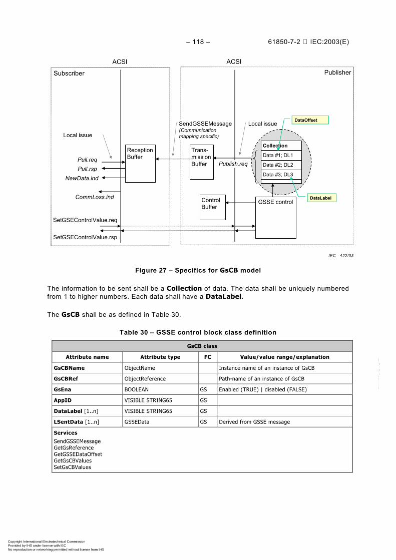
– 118 – 61850-7-2 IEC:2003(E)
PublisherSubscriber
ACSI ACSI
GSSE control
Trans-missionBuffer
ControlBuffer
ReceptionBuffer
Publish.reqPull.reqPull.rsp
NewData.ind
SetGSEControlValue.req
SetGSEControlValue.rsp
Local issue
Local issueSendGSSEMessage(Communicationmapping specific)
CommLoss.ind
Collection
Data #1; DL1
Data #2; DL2
Data #3; DL3
DataLabel
DataOffset
Figure 27 – Specifics for GsCB model
The information to be sent shall be a Collection of data. The data shall be uniquely numberedfrom 1 to higher numbers. Each data shall have a DataLabel.
The GsCB shall be as defined in Table 30.
Table 30 – GSSE control block class definition
GsCB class
Attribute name Attribute type FC Value/value range/explanation
GsCBName ObjectName Instance name of an instance of GsCB
GsCBRef ObjectReference Path-name of an instance of GsCB
GsEna BOOLEAN GS Enabled (TRUE) | disabled (FALSE)
AppID VISIBLE STRING65 GS
DataLabel [1..n] VISIBLE STRING65 GS
LSentData [1..n] GSSEData GS Derived from GSSE message
ServicesSendGSSEMessageGetGsReferenceGetGSSEDataOffsetGetGsCBValuesSetGsCBValues
IEC 422/03
Copyright International Electrotechnical Commission Provided by IHS under license with IEC
Not for ResaleNo reproduction or networking permitted without license from IHS
--``````-`-`,,`,,`,`,,`---

61850-7-2 © IEC:2003(E) – 119 –
15.3.2 Generic substation state event (GSSE) control block class attributes
15.3.2.1 GsCBName – GSSE control name
The attribute GsCBName shall unambiguously identify a GsCB within the scope of a LLN0.
15.3.2.2 GsCBRef – GSSE control reference
The attribute GsCBRef shall be the unique path-name of a GsCB within a LLN0.
The ObjectReference GsCBRef shall be:
LDName/LLN0.GsCBName
15.3.2.3 GsEna – GSSE enable
The attribute GsEna (if set to TRUE) shall indicate that GsCB is currently enabled to sendvalues of the GsCB. If set to FALSE the GsCB shall stop sending GSSE messages.
While being TRUE (GsCB enabled), no changes of attribute values of the GsCB other thandisabling shall be allowed.
If the TWO-PARTY-APPLICATION-ASSOCIATION to the client that has enabled the GsCB islost, the instance of GsCB shall set the attribute to FALSE.
15.3.2.4 AppID – application identification
The attribute AppID shall be a visible string that represents a LOGICAL-DEVICE in which theGsCB is located. The default value of AppID shall be that of the ObjectReference of a GsCB.However, the value may be set to another value as part of a system wide configuration.
NOTE Depending upon the SCSM and actual implementation, it may not be possible to uniquely identify the GSSEcontrol through the control reference. Therefore, a standardized control attribute must be provided to allow thesystem configuration process to be able to uniquely identify the control within the scope of the substation.
15.3.2.5 DataLabel [1..n]
The attribute DataLabel of visible strings shall contain a reference for each entry used withinthe attribute LastSentData. A NULL value shall indicate that that particular LastSentDatadata entry is not in use. The DEFAULT value is a local issue.
The visible string shall hold the value of the ObjectReference if the corresponding element isbeing sent. Otherwise the value of the ObjectReference shall be NULL. The DEFAULT valueshall be GsCBName.
NOTE The attribute DataLabel allows a user to assign a system unique identifier for the application that isissuing the GSSE.
15.3.2.6 LSentData [1..n] – last sent data values
The attribute LSentData shall represent the data values that have been sent with the lastGSSE message.
The maximum for the number of data values shall be at least 24; i.e. the attribute LSentDatashall be capable of holding at least 24 double-bit status values.
NOTE The maximum number of data values may be constrained by the SCSM and local means.
Copyright International Electrotechnical Commission Provided by IHS under license with IEC
Not for ResaleNo reproduction or networking permitted without license from IHS
--``````-`-`,,`,,`,`,,`---

– 120 – 61850-7-2 IEC:2003(E)
15.3.3 GSSE service definitions
15.3.3.1 Overview
For the GsCB the following services are defined:
Service Description
SendGSSEMessage Send GSSE message
GetGsReference Retrieve the DataLabel of a specific value associated with the GSSE message
GetGSSEElementNumber Retrieve the position of the specific value associated with the GSSE messageof a DataLabel
GetGsCBValues Retrieve the attributes of a GsCB
SetGsCBValues Write the attributes of a GsCB
15.3.3.2 SendGSSEMessage
15.3.3.2.1 SendGSSEMessage parameter table
The SendGSSEMessage service shall be used by a GsCB to send a GSSE message over aMULTICAST-APPLICATION-ASSOCIATION.
Parameter name
Request
GSSE message
15.3.3.2.2 Request
15.3.3.2.2.1 GSSE message
The parameter GSSE message shall specify the GSSE message as defined in 15.3.4 of thegiven GsCB.
15.3.3.3 GetGsReference
15.3.3.3.1 GetGsReference parameter table
A client shall use the GetGsReference service to retrieve the DataLabels of specificmembers of the Collection of the referenced GsCB.
Parameter name
Request
GsCBReference
DataOffset [1..n]
Response+
GsCBReference
DataLabel [1..n]
Response–
ServiceError
Copyright International Electrotechnical Commission Provided by IHS under license with IEC
Not for ResaleNo reproduction or networking permitted without license from IHS
--``````-`-`,,`,,`,`,,`---
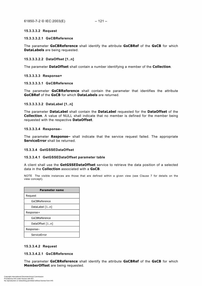
61850-7-2 © IEC:2003(E) – 121 –
15.3.3.3.2 Request
15.3.3.3.2.1 GsCBReference
The parameter GsCBReference shall identify the attribute GsCBRef of the GsCB for whichDataLabels are being requested.
15.3.3.3.2.2 DataOffset [1..n]
The parameter DataOffset shall contain a number identifying a member of the Collection.
15.3.3.3.3 Response+
15.3.3.3.3.1 GsCBReference
The parameter GsCBReference shall contain the parameter that identifies the attributeGoCBRef of the GsCB for which DataLabels are returned.
15.3.3.3.3.2 DataLabel [1..n]
The parameter DataLabel shall contain the DataLabel requested for the DataOffset of theCollection. A value of NULL shall indicate that no member is defined for the member beingrequested with the respective DataOffset.
15.3.3.3.4 Response–
The parameter Response– shall indicate that the service request failed. The appropriateServiceError shall be returned.
15.3.3.4 GetGSSEDataOffset
15.3.3.4.1 GetGSSEDataOffset parameter table
A client shall use the GetGSSEDataOffset service to retrieve the data position of a selecteddata in the Collection associated with a GsCB.
NOTE The visible instances are those that are defined within a given view (see Clause 7 for details on theview concept).
Parameter name
Request
GsCBReference
DataLabel [1..n]
Response+
GsCBReference
DataOffset [1..n]
Response–
ServiceError
15.3.3.4.2 Request
15.3.3.4.2.1 GsCBReference
The parameter GsCBReference shall identify the attribute GsCBRef of the GsCB for whichMemberOffset are being requested.
Copyright International Electrotechnical Commission Provided by IHS under license with IEC
Not for ResaleNo reproduction or networking permitted without license from IHS
--``````-`-`,,`,,`,`,,`---
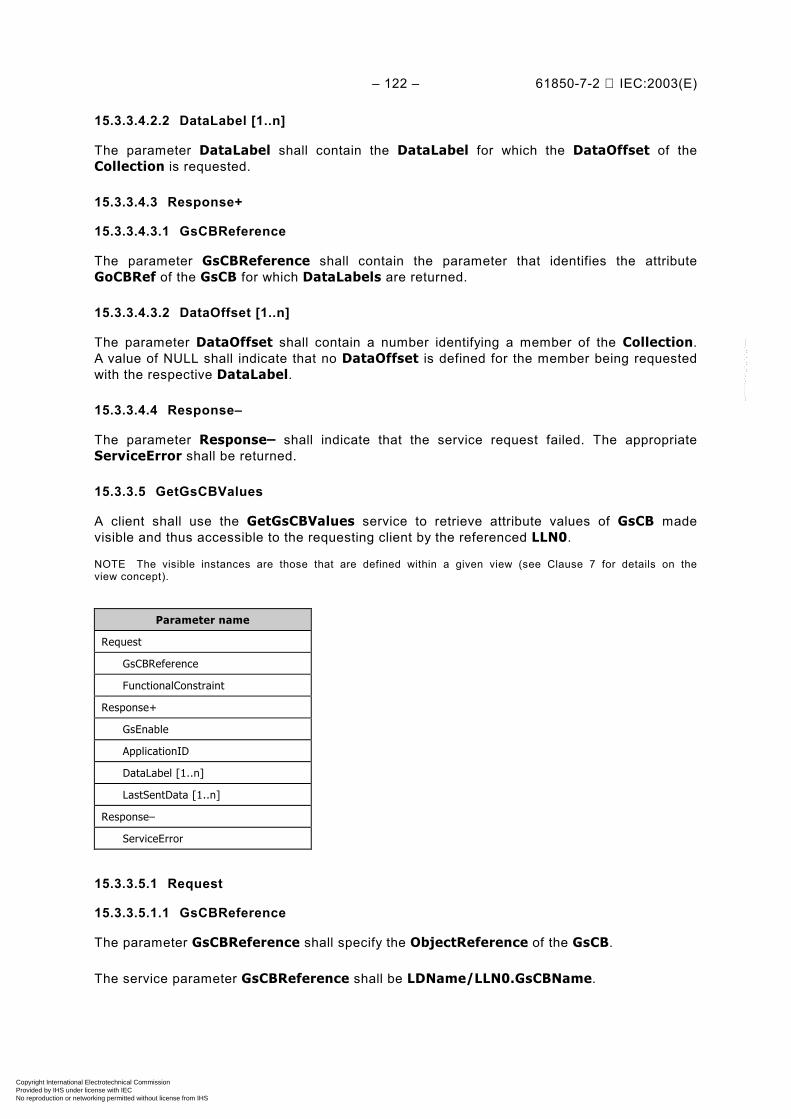
– 122 – 61850-7-2 IEC:2003(E)
15.3.3.4.2.2 DataLabel [1..n]
The parameter DataLabel shall contain the DataLabel for which the DataOffset of theCollection is requested.
15.3.3.4.3 Response+
15.3.3.4.3.1 GsCBReference
The parameter GsCBReference shall contain the parameter that identifies the attributeGoCBRef of the GsCB for which DataLabels are returned.
15.3.3.4.3.2 DataOffset [1..n]
The parameter DataOffset shall contain a number identifying a member of the Collection.A value of NULL shall indicate that no DataOffset is defined for the member being requestedwith the respective DataLabel.
15.3.3.4.4 Response–
The parameter Response– shall indicate that the service request failed. The appropriateServiceError shall be returned.
15.3.3.5 GetGsCBValues
A client shall use the GetGsCBValues service to retrieve attribute values of GsCB madevisible and thus accessible to the requesting client by the referenced LLN0.
NOTE The visible instances are those that are defined within a given view (see Clause 7 for details on theview concept).
Parameter name
Request
GsCBReference
FunctionalConstraint
Response+
GsEnable
ApplicationID
DataLabel [1..n]
LastSentData [1..n]
Response–
ServiceError
15.3.3.5.1 Request
15.3.3.5.1.1 GsCBReference
The parameter GsCBReference shall specify the ObjectReference of the GsCB.
The service parameter GsCBReference shall be LDName/LLN0.GsCBName.
Copyright International Electrotechnical Commission Provided by IHS under license with IEC
Not for ResaleNo reproduction or networking permitted without license from IHS
--``````-`-`,,`,,`,`,,`---
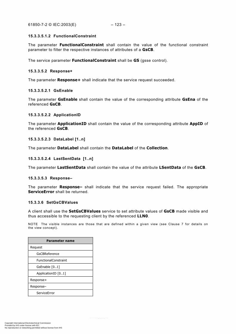
61850-7-2 © IEC:2003(E) – 123 –
15.3.3.5.1.2 FunctionalConstraint
The parameter FunctionalConstraint shall contain the value of the functional constraintparameter to filter the respective instances of attributes of a GsCB.
The service parameter FunctionalConstraint shall be GS (gsse control).
15.3.3.5.2 Response+
The parameter Response+ shall indicate that the service request succeeded.
15.3.3.5.2.1 GsEnable
The parameter GsEnable shall contain the value of the corresponding attribute GsEna of thereferenced GsCB.
15.3.3.5.2.2 ApplicationID
The parameter ApplicationID shall contain the value of the corresponding attribute AppID ofthe referenced GsCB.
15.3.3.5.2.3 DataLabel [1..n]
The parameter DataLabel shall contain the DataLabel of the Collection.
15.3.3.5.2.4 LastSentData [1..n]
The parameter LastSentData shall contain the value of the attribute LSentData of the GsCB.
15.3.3.5.3 Response–
The parameter Response– shall indicate that the service request failed. The appropriateServiceError shall be returned.
15.3.3.6 SetGsCBValues
A client shall use the SetGsCBValues service to set attribute values of GsCB made visible andthus accessible to the requesting client by the referenced LLN0.
NOTE The visible instances are those that are defined within a given view (see Clause 7 for details onthe view concept).
Parameter name
Request
GsCBReference
FunctionalConstraint
GsEnable [0..1]
ApplicationID [0..1]
Response+
Response–
ServiceError
Copyright International Electrotechnical Commission Provided by IHS under license with IEC
Not for ResaleNo reproduction or networking permitted without license from IHS
--``````-`-`,,`,,`,`,,`---

– 124 – 61850-7-2 IEC:2003(E)
15.3.3.6.1 Request
15.3.3.6.1.1 GsCBReference
The parameter GsCBReference shall specify the ObjectReference of the GsCB.
The service parameter GsCBReference shall be LDName/LLN0.GsCBName.
15.3.3.6.1.2 FunctionalConstraint
The parameter FunctionalConstraint shall contain the value of the functional constraintparameter to filter the respective instances of attributes of a GsCB.
The service parameter FunctionalConstraint shall be GS (gsse control).
15.3.3.6.1.3 GsEnable [0..1]
The parameter GsEnable shall contain the value for the corresponding attribute GsEna of thereferenced GsCB.
15.3.3.6.1.4 ApplicationID [0..1]
The parameter ApplicationID shall contain the value for the corresponding attribute AppIDof the referenced GsCB.
15.3.3.6.2 Response+
The parameter Response+ shall indicate that the service request succeeded.
15.3.3.6.3 Response–
The parameter Response– shall indicate that the service request failed. The appropriateServiceError shall be returned.
This service shall return a failure if the service has been issued for any attribute of a GsCBother than GsEnable while GsCB is enabled.
15.3.4 Generic substation state event (GSSE) message
15.3.4.1 Syntax
The abstract GSSE message format shall specify the information to be included in the GSSEmessage. The structure of the GSSE message shall be as specified in Table 31.
A GSSE message shall at least be sent each time when a value from one or more of theLSentData change (for example, a change of status value is detected).
Copyright International Electrotechnical Commission Provided by IHS under license with IEC
Not for ResaleNo reproduction or networking permitted without license from IHS
--``````-`-`,,`,,`,`,,`---
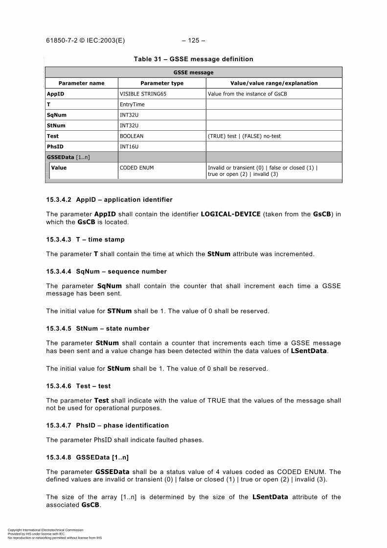
61850-7-2 © IEC:2003(E) – 125 –
Table 31 – GSSE message definition
GSSE message
Parameter name Parameter type Value/value range/explanation
AppID VISIBLE STRING65 Value from the instance of GsCB
T EntryTime
SqNum INT32U
StNum INT32U
Test BOOLEAN (TRUE) test | (FALSE) no-test
PhsID INT16U
GSSEData [1..n]
Value CODED ENUM Invalid or transient (0) | false or closed (1) |true or open (2) | invalid (3)
15.3.4.2 AppID – application identifier
The parameter AppID shall contain the identifier LOGICAL-DEVICE (taken from the GsCB) inwhich the GsCB is located.
15.3.4.3 T – time stamp
The parameter T shall contain the time at which the StNum attribute was incremented.
15.3.4.4 SqNum – sequence number
The parameter SqNum shall contain the counter that shall increment each time a GSSEmessage has been sent.
The initial value for STNum shall be 1. The value of 0 shall be reserved.
15.3.4.5 StNum – state number
The parameter StNum shall contain a counter that increments each time a GSSE messagehas been sent and a value change has been detected within the data values of LSentData.
The initial value for StNum shall be 1. The value of 0 shall be reserved.
15.3.4.6 Test – test
The parameter Test shall indicate with the value of TRUE that the values of the message shallnot be used for operational purposes.
15.3.4.7 PhsID – phase identification
The parameter PhsID shall indicate faulted phases.
15.3.4.8 GSSEData [1..n]
The parameter GSSEData shall be a status value of 4 values coded as CODED ENUM. Thedefined values are invalid or transient (0) | false or closed (1) | true or open (2) | invalid (3).
The size of the array [1..n] is determined by the size of the LSentData attribute of theassociated GsCB.
Copyright International Electrotechnical Commission Provided by IHS under license with IEC
Not for ResaleNo reproduction or networking permitted without license from IHS
--``````-`-`,,`,,`,`,,`---

– 126 – 61850-7-2 IEC:2003(E)
16 Transmission of sampled value class model
16.1 Overview
The transmission of sampled values requires special attention with regard to the timeconstraints. The model provides transmission of sampled values in an organized and time-controlled way so that the combined jitter of sampling and transmission is minimized to adegree that an unambiguous allocation of the samples, times, and sequence is provided.
The model applies to the exchange of values of a DATA-SET. The DATA of the DATA-SET areof the common data class SAV (sampled value as defined in IEC 61850-7-3). A buffer structureshall be defined for the transmission of the sampled values.
The information exchange shall be based on a publisher/subscriber mechanism. The publishershall write the values in a local buffer at the sending side; the subscriber shall read the valuesfrom a local buffer at the receiving side. A time stamp shall be added to the values, so that thesubscriber can check the timeliness of the values. The communication system shall beresponsible to update the local buffers of the subscribers. A sampled value control (SVC) in thepublisher shall be used to control the communication procedure.
Figure 28 gives an overview on the classes and services of the model.
DOcf-attrdc-attr
MX attr
DOcf-attrdc-attr
MX attr
PublisherSubscriber
ACSI ACSI
SVC
DATA:SAVcf-attrdc-attr
MX attr
Trans-missionBuffer
ControlBuffer
ReceptionBuffer
GetDataValue.req
GetDataValue.rsp
Sample.reqPull.reqPull.rsp
NewData.ind
SetSVCValue.req
SetSVCValue.rsp
Local issue
DATA-SET
Local issue
SendSVMessage(Communicationmapping specific)
CommLoss.ind
Member
Member
Member
FCDA1
FCDA2
FCDA3
MemberReference( = Functionallyconstraint DATA-ATTRIBUTE)
Figure 28 – Model for transmission of sampled values
There shall be two methods to exchange sampled values between a publisher and one or moresubscriber. One method shall use the MULTICAST-APPLICATION-ASSOCIATION (multicastsampled value control, MSVCB), the other method shall use the TWO-PARTY-APPLICATION-ASSOCIATION (unicast sampled value control, USVCB).
The producer shall sample the inputs with the specified sample rate. The synchronization ofthis sampling may be done internal or over the network. The samples shall be posted in thetransmission buffer.
IEC 423/03
Copyright International Electrotechnical Commission Provided by IHS under license with IEC
Not for ResaleNo reproduction or networking permitted without license from IHS
--``````-`-`,,`,,`,`,,`---

61850-7-2 © IEC:2003(E) – 127 –
The network embedded scheduler shall send the content of the buffer over the network to thesubscribers. The rate may be a mapping specific parameter. Then the samples shall be placedinto the receive buffers of the subscribers. The arrival of a new series of samples in the receivebuffer shall be signalled to the application.
The model shall provide mechanisms that the subscriber can detect lost samples. If samplesare not be transmitted due to problems in the communication network, the publisher shalldelete these samples.
16.2 Transmission of sampled values using multicast
The transmission of sampled values using multicast (MULTICAST-SAMPLE-VALUE-CONTROL-BLOCK – MSVCB) shall be based on configured configuration in the producerdevice. The data exchange shall be based on the multicast application association. To supportself-descriptive capabilities, any client may read the attributes of the sampled value controlinstance. Authorized clients may modify attributes of the sampled value control.
16.2.1 MSVCB class definition
The MSVCB shall be as defined in Table 32.
Table 32 – MSVCB class definition
MSVCB class
Attribute name Attribute type FC TrgOp Value/value range/explanation
MsvCBNam ObjectName - - Instance name of an instance of MSVCB
MsvCBRef ObjectReference - - Path-name of an instance of MSVCB
SvEna BOOLEAN MS dchg Enabled (TRUE) | disabled (FALSE), DEFAULTFALSE
MsvID VISIBLE STRING65 MS -
DatSet ObjectReference MS dchg
ConfRev INT32U MS dchg
SmpRate INT16U MS - (0..MAX)
OptFlds PACKED LIST MS dchg
refresh-time BOOLEAN
sample-synchronized BOOLEAN
sample-rate BOOLEAN
ServicesSendMSVMessageGetMSVCBValuesSetMSVCBValues
16.2.1.1 MsvCBNam – multicast sampled value control name
The attribute MsvCBNam shall unambiguously identify a MSVCB within the scope of an LLN0.
16.2.1.2 MsvCBRef – multicast sampled value control reference
The attribute MsvCBRef shall be the unique path-name of a MSVCB within an LLN0.
Copyright International Electrotechnical Commission Provided by IHS under license with IEC
Not for ResaleNo reproduction or networking permitted without license from IHS
--``````-`-`,,`,,`,`,,`---

– 128 – 61850-7-2 IEC:2003(E)
The ObjectReference MsvCBRef shall be:
LDName/LLN0.MsvCBNam
16.2.1.3 SvEna – sampled value enable
The attribute SvEna (if set to TRUE) shall indicate that the MSVCB is currently enabled to sendvalues of the MSVCB. If set to FALSE the MSVCB shall stop sending values.
While being TRUE (MSVCB enabled), no changes of attribute values of the MSVCB other thandisabling shall be allowed.
16.2.1.4 MsvID – multicast sampled value identifier
The attribute MSVID shall be a unique identification of the sampled value buffer related to theupdate of the sampled values.
16.2.1.5 DatSet
The attribute DatSet shall specify the reference of the DATA-SET whose values of membersare to be transmitted in the MSVCB message.
16.2.1.6 ConfRev – configuration revision
The attribute ConfRev shall contain a count of the number of times that the configuration withregard to the MSVCB has been changed. Changes that shall be counted are:
– any deletion of a member of the DATA-SET,
– any reordering of members of the DATA-SET,
– any change of a value of the DataAttribute of the DATA-SET whose functional constraintequals CF,
– any change of a value of an attribute of MSVCB (functional constraint of attribute MSVCBequals MS (multicast sampled value control).
The counter shall be incremented when the configuration changes.
The initial value for ConfRev is outside the scope of this standard. The value of 0 shall bereserved. A restart of the IED shall not reset the value.
NOTE Configuration changes of DATA-SETs due to processing of services are not allowed (see DATA-SETmodel). Changes to be taken into account for the ConfRev are those made by local means like systemconfiguration.
16.2.1.7 SmpRate
The attribute SmpRate shall specify the sample rate in units of samples per nominal period.
16.2.1.8 OptFlds – optional fields to include in SV message
The attribute OptFlds shall be the client-specified optional fields to be included in the SVmessage issued by this MSVCB. This attribute defines a subset of the optional header fieldsthat shall be included in the SV message:
– RefrTm (Refresh time, time of refresh activity)
– SmpSynch (Samples synchronized, samples are synchronized by clock signals) , and
– SmpRate (sample rate from the instance of MSVCB)
Copyright International Electrotechnical Commission Provided by IHS under license with IEC
Not for ResaleNo reproduction or networking permitted without license from IHS
--``````-`-`,,`,,`,`,,`---
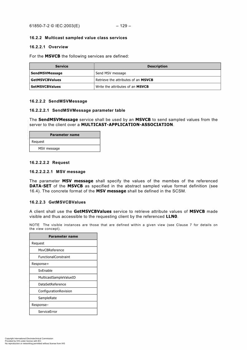
61850-7-2 © IEC:2003(E) – 129 –
16.2.2 Multicast sampled value class services
16.2.2.1 Overview
For the MSVCB the following services are defined:
Service Description
SendMSVMessage Send MSV message
GetMSVCBValues Retrieve the attributes of an MSVCB
SetMSVCBValues Write the attributes of an MSVCB
16.2.2.2 SendMSVMessage
16.2.2.2.1 SendMSVMessage parameter table
The SendMSVMessage service shall be used by an MSVCB to send sampled values from theserver to the client over a MULTICAST-APPLICATION-ASSOCIATION.
Parameter name
Request
MSV message
16.2.2.2.2 Request
16.2.2.2.2.1 MSV message
The parameter MSV message shall specify the values of the membes of the referencedDATA-SET of the MSVCB as specified in the abstract sampled value format definition (see16.4). The concrete format of the MSV message shall be defined in the SCSM.
16.2.2.3 GetMSVCBValues
A client shall use the GetMSVCBValues service to retrieve attribute values of MSVCB madevisible and thus accessible to the requesting client by the referenced LLN0.
NOTE The visible instances are those that are defined within a given view (see Clause 7 for details onthe view concept).
Parameter name
Request
MsvCBReference
FunctionalConstraint
Response+
SvEnable
MulticastSampleValueID
DataSetReference
ConfigurationRevision
SampleRate
Response–
ServiceError
Copyright International Electrotechnical Commission Provided by IHS under license with IEC
Not for ResaleNo reproduction or networking permitted without license from IHS
--``````-`-`,,`,,`,`,,`---
– 130 – 61850-7-2 IEC:2003(E)
16.2.2.3.1 Request
16.2.2.3.1.1 MsvCBReference
The parameter MsvCBReference shall specify the ObjectReference of the MSVCB.
The service parameter MsvCBReference shall be LDName/LLN0.MsvCBNam.
16.2.2.3.1.2 FunctionalConstraint
The parameter FunctionalConstraint shall contain the value of the functional constraintparameter to filter the respective instances of attributes of a MSVCB.
The service parameter FunctionalConstraint shall be MS (multicast sampled value control).
16.2.2.3.2 Response+
The parameter Response+ shall indicate that the service request succeeded.
16.2.2.3.2.1 SvEnable
The parameter SvEnable shall contain the value of the corresponding attribute SvEna of thereferenced MSVCB.
16.2.2.3.2.2 MulticastSampleValueID
The parameter MulticastSampleValueID shall contain the value of the correspondingattribute MsvID of the referenced MSVCB.
16.2.2.3.2.3 DataSetReference
The parameter DataSetReference shall contain the value of the corresponding attributeDatSet of the referenced MSVCB.
16.2.2.3.2.4 ConfigurationRevision
The parameter ConfigurationRevision shall contain the value of the corresponding attributeConfRev of the MSVCB.
16.2.2.3.2.5 SampleRate
The parameter SampleRate shall contain the value of the corresponding attribute SmpRate ofthe MSVCB.
16.2.2.3.3 Response–
The parameter Response– shall indicate that the service request failed. The appropriateServiceError shall be returned.
16.2.2.4 SetMSVCBValues
A client shall use the SetMSVCB Values service to set attribute values of MSVCB madevisible and thus accessible to the requesting client by the referenced LLN0.
NOTE The visible instances are those that are defined within a given view (see Clause 7 for details onthe view concept).
Copyright International Electrotechnical Commission Provided by IHS under license with IEC
Not for ResaleNo reproduction or networking permitted without license from IHS
--``````-`-`,,`,,`,`,,`---

61850-7-2 © IEC:2003(E) – 131 –
Parameter name
Request
MsvCBReference
FunctionalConstraint
SvEnable [0..1]
MulticastSampleValueID [0..1]
DataSetReference [0..1]
SampleRate [0..1]
Response+
Response–
ServiceError
16.2.2.4.1 Request
16.2.2.4.1.1 MsvCBReference
The parameter MsvCBReference shall specify the ObjectReference of the MSVCB.
The service parameter MsvCBReference shall be LDName/LLN0.MsvCBNam.
16.2.2.4.1.2 FunctionalConstraint
The parameter FunctionalConstraint shall contain the value of the functional constraintparameter to filter the respective instances of attributes of a MSVCB.
The service parameter FunctionalConstraint shall be MS (multicast sampled value control).
16.2.2.4.1.3 SvEnable [0..1]
The parameter SvEnable shall contain the value for the corresponding attribute SvEna of thereferenced MSVCB.
16.2.2.4.1.4 MulticastSampleValueID [0..1]
The parameter MulticastSampleValueID shall contain the value for the correspondingattribute MsvID of the referenced MSVCB.
16.2.2.4.1.5 DataSetReference [0..1]
The parameter DataSetReference shall contain the value for the corresponding attributeDatSet of the referenced MSVCB.
16.2.2.4.1.6 SampleRate [0..1]
The parameter SampleRate shall contain the value for the corresponding attribute SmpRateof the MSVCB.
16.2.2.4.2 Response+
The parameter Response+ shall indicate that the service request succeeded.
Copyright International Electrotechnical Commission Provided by IHS under license with IEC
Not for ResaleNo reproduction or networking permitted without license from IHS
--``````-`-`,,`,,`,`,,`---

– 132 – 61850-7-2 IEC:2003(E)
16.2.2.4.3 Response–
The parameter Response– shall indicate that the service request failed. The appropriateServiceError shall be returned.
This service shall return a failure if the service has been issued for any attribute of a MSVCBother than SvEnable while MSVCB is enabled.
16.3 Transmission of sampled values using unicast
The transmission of sampled values using unicast (UNICAST-SAMPLE-VALUE-CONTROL-BLOCK – USVCB) shall be based on two-party application associations. The subscriber shallestablish the association with the producer. The subscriber may then configure the class andenable the transmission of the sampled values with the attribute SvEna. When the associationis released, the transmission of the sampled values shall stop and the instance of the controlclass shall be released.
The samples shall be sent using the two-party application association.
16.3.1 USVCB class definition
The USVCB shall be as defined in Table 33.
Table 33 – USVCB class definition
USVCB class
Attribute name Attribute type FC TrgOp Value/value range/explanation
UsvCBNam ObjectName - - Instance name of an instance of UNICAST-SVC
UsvCBRef ObjectReference - - Path-name of an instance of UNIICAST-SVC
SvEna BOOLEAN US dchg Enabled (TRUE) | disabled (FALSE), DEFAULTFALSE
Resv BOOLEAN US -
UsvID VISIBLE STRING65 US -
DatSet ObjectReference US dchg
ConfRev INT32U US dchg
SmpRate INT16U US dchg (0..MAX)
OptFlds PACKED LIST US dchg
refresh-time BOOLEAN
sample-synchronized BOOLEAN
sample-rate BOOLEAN
ServicesSendUSVMessageGetUSVCBValuesSetUSVCBValues
16.3.1.1 UsvCBNam – unicast sampled value control name
The attribute UsvCBNam shall unambiguously identify a USVCB within the scope of a LLN0.
Copyright International Electrotechnical Commission Provided by IHS under license with IEC
Not for ResaleNo reproduction or networking permitted without license from IHS
--``````-`-`,,`,,`,`,,`---
61850-7-2 © IEC:2003(E) – 133 –
16.3.1.2 UsvCBRef – unicast sampled value control reference
The attribute UsvCBRef shall be the unique path-name of a USVCB within a LLN0.
The ObjectReference UsvCBRef shall be:
LDName/LLN0.UsvCBNam
16.3.1.3 SvEna – sampled value enable
The attribute SvEna (if set to TRUE) shall indicate that the USVCB is currently enabled to sendvalues of the USVCB. If set to FALSE the USVCB shall stop issuing reports.
While being TRUE (USVCB enabled), no changes of attribute values of USVCB other thandisabling shall be allowed.
If the TWO-PARTY-APPLICATION-ASSOCIATION to the client that has enabled the USVCBis lost, the USVCB shall set the attribute to FALSE.
16.3.1.4 Resv – reserve USVCB
The attribute Resv (if set to TRUE) shall indicate that the USVCB is currently exclusivelyreserved for the client that has set the value to TRUE. Other clients shall not be allowed to aset any attribute of that USVCB.
If the TWO-PARTY-APPLICATION-ASSOCIATION to the client that has set this attribute toTRUE is lost, the USVCB shall set the attribute to FALSE.
NOTE The attribute Resv functions as a semaphore for the configuration, enabling and disabling of the USVCB.
16.3.1.5 UsvID
The attribute UsvID shall be a unique identification of the sampled value buffer related to theupdate of the sampled values.
16.3.1.6 DatSet
The attribute DatRef shall specify the reference of the DATA-SET whose values of membersare to be transmitted in the USVCB message.
16.3.1.7 ConfRev – configuration revision
The attribute ConfRev shall contain a count of the number of times that the configuration withregard to the USVCB has been changed. Changes that shall be counted are:
– any deletion of a member of the DATA-SET,
– any reordering of members of the DATA-SET,
– any change of a value of the DataAttribute of the DATA-SET whose functional constraintequals cf.
– any change of a value of an attribute of USVCB (functional constraint of attribute USVCBequals US).
The counter shall be incremented when the configuration changes.
Copyright International Electrotechnical Commission Provided by IHS under license with IEC
Not for ResaleNo reproduction or networking permitted without license from IHS
--``````-`-`,,`,,`,`,,`---
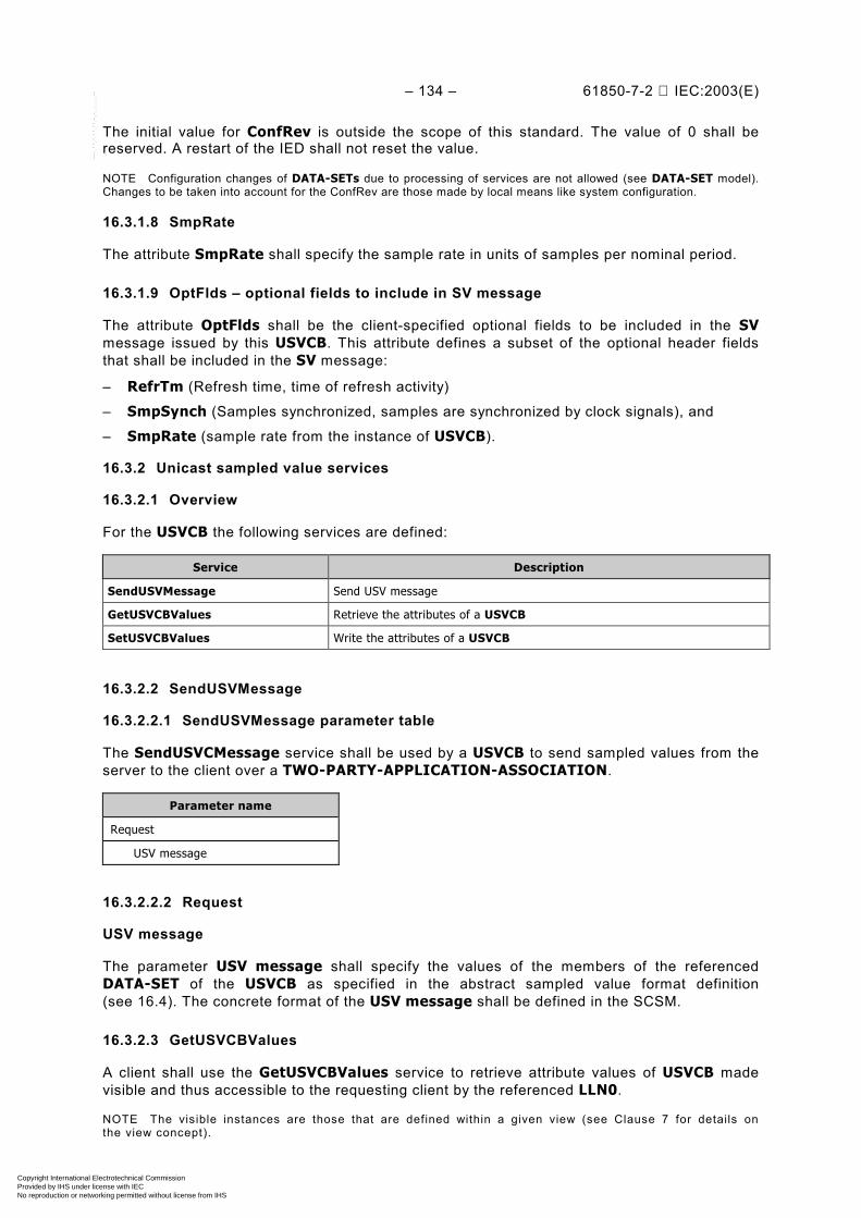
– 134 – 61850-7-2 IEC:2003(E)
The initial value for ConfRev is outside the scope of this standard. The value of 0 shall bereserved. A restart of the IED shall not reset the value.
NOTE Configuration changes of DATA-SETs due to processing of services are not allowed (see DATA-SET model).Changes to be taken into account for the ConfRev are those made by local means like system configuration.
16.3.1.8 SmpRate
The attribute SmpRate shall specify the sample rate in units of samples per nominal period.
16.3.1.9 OptFlds – optional fields to include in SV message
The attribute OptFlds shall be the client-specified optional fields to be included in the SVmessage issued by this USVCB. This attribute defines a subset of the optional header fieldsthat shall be included in the SV message:
– RefrTm (Refresh time, time of refresh activity)
– SmpSynch (Samples synchronized, samples are synchronized by clock signals), and
– SmpRate (sample rate from the instance of USVCB).
16.3.2 Unicast sampled value services
16.3.2.1 Overview
For the USVCB the following services are defined:
Service Description
SendUSVMessage Send USV message
GetUSVCBValues Retrieve the attributes of a USVCB
SetUSVCBValues Write the attributes of a USVCB
16.3.2.2 SendUSVMessage
16.3.2.2.1 SendUSVMessage parameter table
The SendUSVCMessage service shall be used by a USVCB to send sampled values from theserver to the client over a TWO-PARTY-APPLICATION-ASSOCIATION.
Parameter name
Request
USV message
16.3.2.2.2 Request
USV message
The parameter USV message shall specify the values of the members of the referencedDATA-SET of the USVCB as specified in the abstract sampled value format definition(see 16.4). The concrete format of the USV message shall be defined in the SCSM.
16.3.2.3 GetUSVCBValues
A client shall use the GetUSVCBValues service to retrieve attribute values of USVCB madevisible and thus accessible to the requesting client by the referenced LLN0.
NOTE The visible instances are those that are defined within a given view (see Clause 7 for details onthe view concept).
Copyright International Electrotechnical Commission Provided by IHS under license with IEC
Not for ResaleNo reproduction or networking permitted without license from IHS
--``````-`-`,,`,,`,`,,`---
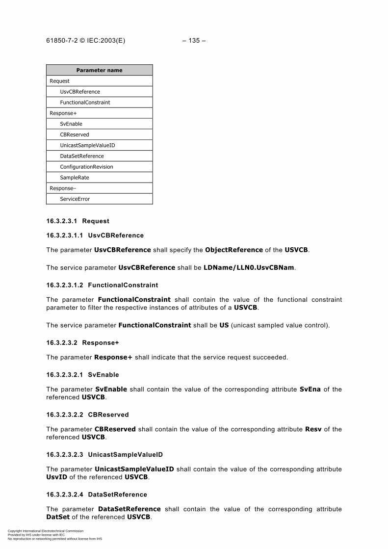
61850-7-2 © IEC:2003(E) – 135 –
Parameter name
Request
UsvCBReference
FunctionalConstraint
Response+
SvEnable
CBReserved
UnicastSampleValueID
DataSetReference
ConfigurationRevision
SampleRate
Response–
ServiceError
16.3.2.3.1 Request
16.3.2.3.1.1 UsvCBReference
The parameter UsvCBReference shall specify the ObjectReference of the USVCB.
The service parameter UsvCBReference shall be LDName/LLN0.UsvCBNam.
16.3.2.3.1.2 FunctionalConstraint
The parameter FunctionalConstraint shall contain the value of the functional constraintparameter to filter the respective instances of attributes of a USVCB.
The service parameter FunctionalConstraint shall be US (unicast sampled value control).
16.3.2.3.2 Response+
The parameter Response+ shall indicate that the service request succeeded.
16.3.2.3.2.1 SvEnable
The parameter SvEnable shall contain the value of the corresponding attribute SvEna of thereferenced USVCB.
16.3.2.3.2.2 CBReserved
The parameter CBReserved shall contain the value of the corresponding attribute Resv of thereferenced USVCB.
16.3.2.3.2.3 UnicastSampleValueID
The parameter UnicastSampleValueID shall contain the value of the corresponding attributeUsvID of the referenced USVCB.
16.3.2.3.2.4 DataSetReference
The parameter DataSetReference shall contain the value of the corresponding attributeDatSet of the referenced USVCB.
Copyright International Electrotechnical Commission Provided by IHS under license with IEC
Not for ResaleNo reproduction or networking permitted without license from IHS
--``````-`-`,,`,,`,`,,`---
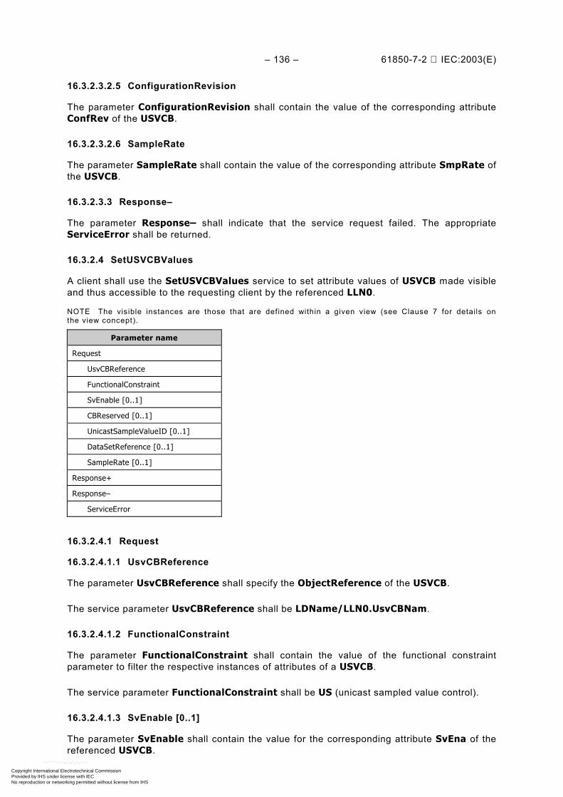
– 136 – 61850-7-2 IEC:2003(E)
16.3.2.3.2.5 ConfigurationRevision
The parameter ConfigurationRevision shall contain the value of the corresponding attributeConfRev of the USVCB.
16.3.2.3.2.6 SampleRate
The parameter SampleRate shall contain the value of the corresponding attribute SmpRate ofthe USVCB.
16.3.2.3.3 Response–
The parameter Response– shall indicate that the service request failed. The appropriateServiceError shall be returned.
16.3.2.4 SetUSVCBValues
A client shall use the SetUSVCBValues service to set attribute values of USVCB made visibleand thus accessible to the requesting client by the referenced LLN0.
NOTE The visible instances are those that are defined within a given view (see Clause 7 for details onthe view concept).
Parameter name
Request
UsvCBReference
FunctionalConstraint
SvEnable [0..1]
CBReserved [0..1]
UnicastSampleValueID [0..1]
DataSetReference [0..1]
SampleRate [0..1]
Response+
Response–
ServiceError
16.3.2.4.1 Request
16.3.2.4.1.1 UsvCBReference
The parameter UsvCBReference shall specify the ObjectReference of the USVCB.
The service parameter UsvCBReference shall be LDName/LLN0.UsvCBNam.
16.3.2.4.1.2 FunctionalConstraint
The parameter FunctionalConstraint shall contain the value of the functional constraintparameter to filter the respective instances of attributes of a USVCB.
The service parameter FunctionalConstraint shall be US (unicast sampled value control).
16.3.2.4.1.3 SvEnable [0..1]
The parameter SvEnable shall contain the value for the corresponding attribute SvEna of thereferenced USVCB.
Copyright International Electrotechnical Commission Provided by IHS under license with IEC
Not for ResaleNo reproduction or networking permitted without license from IHS
--``````-`-`,,`,,`,`,,`---
61850-7-2 © IEC:2003(E) – 137 –
16.3.2.4.1.4 CBReserved
The parameter CBReserved shall contain the value for the corresponding attribute Resv of thereferenced USVCB.
16.3.2.4.1.5 UnicastSampleValueID [0..1]
The parameter UnicastSampleValueID shall contain the value for the corresponding attributeUsvID of the referenced USVCB.
16.3.2.4.1.6 DataSetReference [0..1]
The parameter DataSetReference shall contain the value for the corresponding attributeDatSet of the referenced USVCB.
16.3.2.4.1.7 SampleRate [0..1]
The parameter SampleRate shall contain the value for the corresponding attribute SmpRateof the USVCB.
16.3.2.4.2 Response+
The parameter Response+ shall indicate that the service request succeeded.
16.3.2.4.3 Response–
The parameter Response– shall indicate that the service request failed. The appropriateServiceError shall be returned.
This service shall return a failure if the service has been issued for any attribute of a USVCBother than SvEnable while USVCB is enabled.
16.4 Sampled value format
The abstract sampled value format used for the sampled value message shall be as follows:
Copyright International Electrotechnical Commission Provided by IHS under license with IEC
Not for ResaleNo reproduction or networking permitted without license from IHS
--``````-`-`,,`,,`,`,,`---

– 138 – 61850-7-2 IEC:2003(E)
Table 34 – Sampled value (SV) format definition
Sampled value format
Parameter name Parameter type Value/value range/explanation
MsvID or UsvID VISIBLE STRING65 Value from the MSVCB or USVCB
OptFlds a Optional fields to be included in the SV message
DatSet ObjectReference Value from the MSVCB or USVCB
Sample [1..n]
Value (*) (*) The value of the member of the instance of theDATA-SET. Type of the common data classes is SAV(sampled analogue value) as defined in IEC 61850-7-3
SmpCnt INT16U Sample counter
RefrTm EntryTime OPTIONAL; time of refresh activity
ConfRev INT32U Configuration revision number from the instance ofMSVCB or USVCB
SmpSynch BOOLEAN OPTIONAL; samples are synchronized by clock signals
SmpRate INT16U OPTIONAL; sample rate from the instance of MSVCBor USVCB
a The type and value of this parameter shall be derived from the attribute OptFlds of the respective USVCB orMSVCB.
16.4.1 MsvID or UsvID
The parameter MsvID or UsvID shall contain the values of the attributes MsvID or UsvID ofthe MSVCB or USVCB to be included in the sampled value message.
16.4.2 OptFlds
The parameter OptFlds shall specify which of the optional fields (RefrTm, SmpSynch andSmpRate) are included in the sampled value message. If the attribute of the sampled valuecontrol block refresh-time (sample-rate, sample-synchronized)is TRUE then the field RefrTm(SmpSynch or SmpRate) shall be contained in the sampled value message.
The parameter OptFlds shall be derived from the attribute OptFlds of the respective USVCBor MSVCB.
16.4.3 DatSet
The parameter DatSet (taken from the MsvID or UsvID) shall contain the ObjectReferenceof the DATA-SET whose values of the members are transmitted in the message.
16.4.4 Sample [1..n]
The parameter Sample shall contain the value of a member of DATA-SET sampled ata given time.
16.4.5 SmpCnt
The parameter SmpCnt shall contain the values of a counter, which is incremented each timea new sample of the analogue value is taken. The sample values shall be kept in the rightorder. If the counter is used to indicate time consistency of various sampled values, thecounter shall be reset by an external synchronization event.
NOTE The external synchronization event is outside this part of the standard; details can be found in a SCSM.
Copyright International Electrotechnical Commission Provided by IHS under license with IEC
Not for ResaleNo reproduction or networking permitted without license from IHS
--``````-`-`,,`,,`,`,,`---

61850-7-2 © IEC:2003(E) – 139 –
16.4.6 RefrTm
The parameter RefrTm shall contain the time when the transmission buffer has been refreshedlocally.
NOTE The semantic of the RefrTm is defined in the SCSM. This time may be used by the subscriber to check thevalidity of the data.
16.4.7 ConfRev
The parameter ConfRev shall contain the value of the attribute ConfRev of the MSVCB orUSVCB.
16.4.8 SmpSynch
The parameter SmpRate shall indicate whether the sampled analogue values sent by theMSVCB or USVCB are synchronized by clock signals.
16.4.9 SmpRate
The parameter SmpRate shall contain the value of the attribute SmpRate of the MSVCB orUSVCB.
17 CONTROL class model
17.1 Introduction
DATA related to external devices, control outputs, or other internal functions may require to becontrolled by a client. The control model provides services to operate on DATA withDataAttribute having the functional constraint FC (=CO or SP). The DATA providingcontrollable DataAttributes shall be of one of the common DATA classes defined inIEC 61850-7-3, for example:
– Controllable single point (SPC)– Controllable double point (DPC)– Controllable integer status (INC)– Binary controlled step position information (BSC)– Integer controlled step position information (ISC)– Controllable analogue set point (APC)
NOTE This clause makes use of the term “control object”. A control object can be any DATA based on one of theabove-listed common data classes.
The control model consists of
– specification of services;– a behaviour described with state machines.
The control model defines the following services:
– Select (Sel) / SelectWithValue (SelVal)– Cancel– Operate (Oper) / TimeActivatedOperate (TimOper)– CommandTermination (CmdTerm)
NOTE The abbreviations for these services may be used in the SCSM.
Copyright International Electrotechnical Commission Provided by IHS under license with IEC
Not for ResaleNo reproduction or networking permitted without license from IHS
--``````-`-`,,`,,`,`,,`---
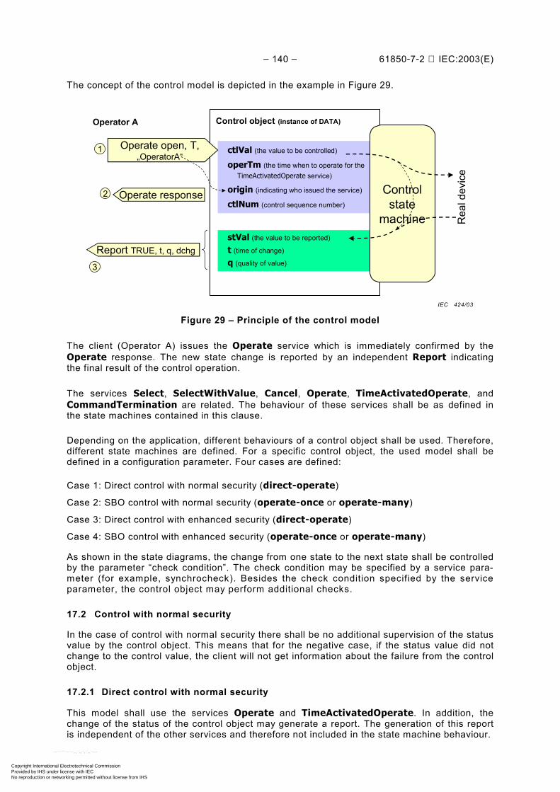
– 140 – 61850-7-2 IEC:2003(E)
The concept of the control model is depicted in the example in Figure 29.
Control object (instance of DATA)
ctlVal (the value to be controlled)
operTm (the time when to operate for theTimeActivatedOperate service)
origin (indicating who issued the service)
ctlNum (control sequence number)
stVal (the value to be reported)
t (time of change)
q (quality of value)
Controlstate
machine
Operate open, T,„OperatorA“
Report TRUE, t, q, dchg
1
3
Rea
l dev
ice
Operate response2
Operator A
Figure 29 – Principle of the control model
The client (Operator A) issues the Operate service which is immediately confirmed by theOperate response. The new state change is reported by an independent Report indicatingthe final result of the control operation.
The services Select, SelectWithValue, Cancel, Operate, TimeActivatedOperate, andCommandTermination are related. The behaviour of these services shall be as defined inthe state machines contained in this clause.
Depending on the application, different behaviours of a control object shall be used. Therefore,different state machines are defined. For a specific control object, the used model shall bedefined in a configuration parameter. Four cases are defined:
Case 1: Direct control with normal security (direct-operate)
Case 2: SBO control with normal security (operate-once or operate-many)
Case 3: Direct control with enhanced security (direct-operate)
Case 4: SBO control with enhanced security (operate-once or operate-many)
As shown in the state diagrams, the change from one state to the next state shall be controlledby the parameter “check condition”. The check condition may be specified by a service para-meter (for example, synchrocheck). Besides the check condition specified by the serviceparameter, the control object may perform additional checks.
17.2 Control with normal security
In the case of control with normal security there shall be no additional supervision of the statusvalue by the control object. This means that for the negative case, if the status value did notchange to the control value, the client will not get information about the failure from the controlobject.
17.2.1 Direct control with normal security
This model shall use the services Operate and TimeActivatedOperate. In addition, thechange of the status of the control object may generate a report. The generation of this reportis independent of the other services and therefore not included in the state machine behaviour.
IEC 424/03
Copyright International Electrotechnical Commission Provided by IHS under license with IEC
Not for ResaleNo reproduction or networking permitted without license from IHS
--``````-`-`,,`,,`,`,,`---
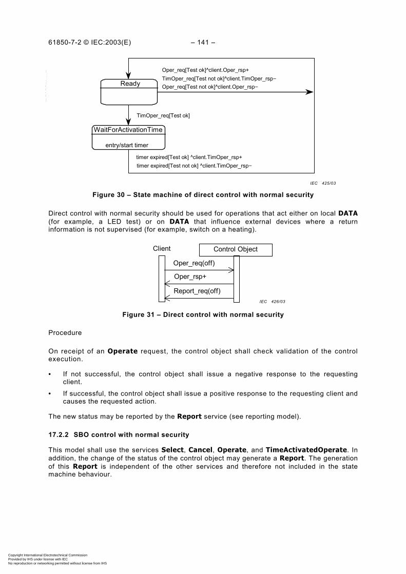
61850-7-2 © IEC:2003(E) – 141 –
Ready Oper_req[Test not ok]^client.Oper_rsp−
WaitForActivationTime
entry/start timer
TimOper_req[Test not ok]^client.TimOper_rsp−Oper_req[Test ok]^client.Oper_rsp+
TimOper_req[Test ok]
timer expired[Test ok] ^client.TimOper_rsp+timer expired[Test not ok] ^client.TimOper_rsp−
Figure 30 – State machine of direct control with normal security
Direct control with normal security should be used for operations that act either on local DATA(for example, a LED test) or on DATA that influence external devices where a returninformation is not supervised (for example, switch on a heating).
Client Control Object
Oper_req(off)
Oper_rsp+
Report_req(off)
Figure 31 – Direct control with normal security
Procedure
On receipt of an Operate request, the control object shall check validation of the controlexecution.
• If not successful, the control object shall issue a negative response to the requestingclient.
• If successful, the control object shall issue a positive response to the requesting client andcauses the requested action.
The new status may be reported by the Report service (see reporting model).
17.2.2 SBO control with normal security
This model shall use the services Select, Cancel, Operate, and TimeActivatedOperate. Inaddition, the change of the status of the control object may generate a Report. The generationof this Report is independent of the other services and therefore not included in the statemachine behaviour.
IEC 425/03
IEC 426/03
Copyright International Electrotechnical Commission Provided by IHS under license with IEC
Not for ResaleNo reproduction or networking permitted without license from IHS
--``````-`-`,,`,,`,`,,`---
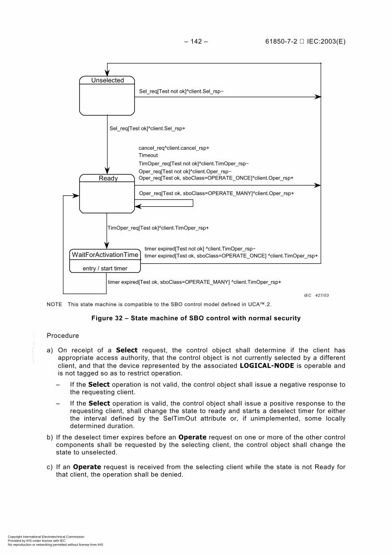
– 142 – 61850-7-2 IEC:2003(E)
ReadyOper_req[Test not ok]^client.Oper_rsp−
WaitForActivationTime
entry / start timer
TimOper_req[Test not ok]^client.TimOper_rsp−
Oper_req[Test ok, sboClass=OPERATE_MANY]^client.Oper_rsp+
TimOper_req[Test ok]^client.TimOper_rsp+
timer expired[Test ok, sboClass=OPERATE_MANY] ^client.TimOper_rsp+
Unselected
Timeoutcancel_req^client.cancel_rsp+
timer expired[Test not ok] ^client.TimOper_rsp−
Sel_req[Test not ok]^client.Sel_rsp−
Sel_req[Test ok]^client.Sel_rsp+
timer expired[Test ok, sboClass=OPERATE_ONCE] ^client.TimOper_rsp+
Oper_req[Test ok, sboClass=OPERATE_ONCE]^client.Oper_rsp+
NOTE This state machine is compatible to the SBO control model defined in UCA™.2.
Figure 32 – State machine of SBO control with normal security
Procedure
a) On receipt of a Select request, the control object shall determine if the client hasappropriate access authority, that the control object is not currently selected by a differentclient, and that the device represented by the associated LOGICAL-NODE is operable andis not tagged so as to restrict operation.
– If the Select operation is not valid, the control object shall issue a negative response tothe requesting client.
– If the Select operation is valid, the control object shall issue a positive response to therequesting client, shall change the state to ready and starts a deselect timer for eitherthe interval defined by the SelTimOut attribute or, if unimplemented, some locallydetermined duration.
b) If the deselect timer expires before an Operate request on one or more of the other controlcomponents shall be requested by the selecting client, the control object shall change thestate to unselected.
c) If an Operate request is received from the selecting client while the state is not Ready forthat client, the operation shall be denied.
IEC 427/03
Copyright International Electrotechnical Commission Provided by IHS under license with IEC
Not for ResaleNo reproduction or networking permitted without license from IHS
--``````-`-`,,`,,`,`,,`---

61850-7-2 © IEC:2003(E) – 143 –
d) On receipt of an Operate request, the control object shall check validation of the controlexecution.
– If not successful, the control object shall issue a negative response to the requestingclient.
– If successful, the control object shall issue a positive response to the requesting clientand shall cause the requested action by activating a binary output (or sending anequivalent signal on a process bus). The control object shall turn to the stateWaitForActivationTime.
17.3 Control with enhanced security
17.3.1 Introduction
In the case of control with enhanced security there shall be an additional supervision of thestatus value by the control object. Each command sequence shall be terminated by aCommandTermination service primitive.
17.3.2 Direct control with enhanced security
This model shall use the services Operate, TimeActivatedOperate, and Command-Termination. In addition, the change of the status of the control object may generate aReport. The generation of this Report is related to the other services and thereforeincluded in the state machine behaviour.
Ready
WaitForChange
entry/activate outputstate (between)/-
exit/deactivate output
WaitForActivationTime
entry/start timer
TimOper_req[Test not ok]^client.TimOper_rsp−
Oper_req[Test ok]^client.Oper_rsp+
TimOper_req[Test ok]^client.TimOper_rsp+
timer expired[Test ok]^client.TimOper_rsp+
timeout[state(between)]^client.Report_req,client.CmdTerm_req−
timer expired[Test not ok]^client.TimOper_rsp−
Oper_req[Test not ok]^client.Oper_rsp−
state(new_valid)^client.Report_req,client.CmdTerm_req+timeout[state(old)]^client.CmdTerm_req−
timeout[state(between)]^client.Report_req,client.CmdTerm_req−
state(new_valid)^client.Report_req,client.CmdTerm_req+timeout[state(old)]^client.CmdTerm_req−
Cancel_req^client.Cancel_rsp+
Figure 33 – State machine of direct control with enhanced security
IEC 428/03
Copyright International Electrotechnical Commission Provided by IHS under license with IEC
Not for ResaleNo reproduction or networking permitted without license from IHS
--``````-`-`,,`,,`,`,,`---
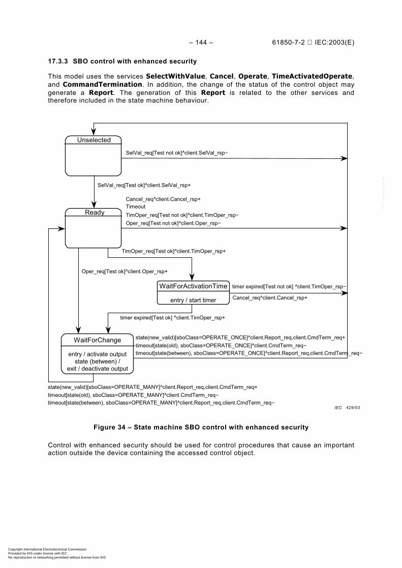
– 144 – 61850-7-2 IEC:2003(E)
17.3.3 SBO control with enhanced security
This model uses the services SelectWithValue, Cancel, Operate, TimeActivatedOperate,and CommandTermination. In addition, the change of the status of the control object maygenerate a Report. The generation of this Report is related to the other services andtherefore included in the state machine behaviour.
Ready
WaitForChange
entry / activate outputstate (between) /
exit / deactivate output
Oper_req[Test not ok]^client.Oper_rsp−
WaitForActivationTime
entry / start timer
TimOper_req[Test not ok]^client.TimOper_rsp−
Oper_req[Test ok]^client.Oper_rsp+
TimOper_req[Test ok]^client.TimOper_rsp+
timer expired[Test ok] ^client.TimOper_rsp+
Unselected
TimeoutCancel_req^client.Cancel_rsp+
timer expired[Test not ok] ^client.TimOper_rsp−
SelVal_req[Test not ok]^client.SelVal_rsp−
SelVal_req[Test ok]^client.SelVal_rsp+
timeout[state(between), sboClass=OPERATE_ONCE]^client.Report_req,client.CmdTerm_req−
state(new_valid)[sboClass=OPERATE_ONCE]^client.Report_req,client.CmdTerm_req+timeout[state(old), sboClass=OPERATE_ONCE]^client.CmdTerm_req−
timeout[state(between), sboClass=OPERATE_MANY]^client.Report_req,client.CmdTerm_req−
state(new_valid)[sboClass=OPERATE_MANY]^client.Report_req,client.CmdTerm_req+timeout[state(old), sboClass=OPERATE_MANY]^client.CmdTerm_req−
Cancel_req^client.Cancel_rsp+
Figure 34 – State machine SBO control with enhanced security
Control with enhanced security should be used for control procedures that cause an importantaction outside the device containing the accessed control object.
IEC 429/03
Copyright International Electrotechnical Commission Provided by IHS under license with IEC
Not for ResaleNo reproduction or networking permitted without license from IHS
--``````-`-`,,`,,`,`,,`---
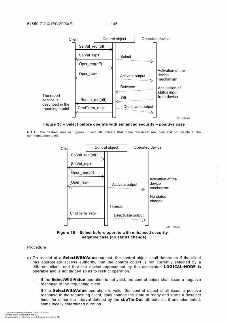
61850-7-2 © IEC:2003(E) – 145 –
Client Control object Operated device
SelVal_req (off)
SelVal_rsp+
Oper_req(off)
Oper_rsp+ Activate output
Between
Off
Activation of thedevicemechanism
Report_req(off)
Acquisition ofstatus inputfrom device
Deactivate outputCmdTerm_req+
The reportservice isdescribed in thereporting model
Select
Figure 35 – Select before operate with enhanced security – positive case
NOTE The dashed lines in Figures 35 and 36 indicate that these “services” are local and not visible at thecommunication level.
Client Control object Operated device
SelVal_req (off)
SelVal_rsp+
Oper_req(off)
Oper_rsp+ Activate output
Timeout
Activation of thedevicemechanism
No statuschange
Deactivate outputCmdTerm_req−
Figure 36 – Select before operate with enhanced security –negative case (no status change)
Procedure
a) On receipt of a SelectWithValue request, the control object shall determine if the clienthas appropriate access authority, that the control object is not currently selected by adifferent client, and that the device represented by the associated LOGICAL-NODE isoperable and is not tagged so as to restrict operation.
– If the SelectWithValue operation is not valid, the control object shall issue a negativeresponse to the requesting client.
– If the SelectWithValue operation is valid, the control object shall issue a positiveresponse to the requesting client, shall change the state to ready and starts a deselecttimer for either the interval defined by the sboTimOut attribute or, if unimplemented,some locally determined duration.
IEC 430/03
IEC 431/03
Copyright International Electrotechnical Commission Provided by IHS under license with IEC
Not for ResaleNo reproduction or networking permitted without license from IHS
--``````-`-`,,`,,`,`,,`---

– 146 – 61850-7-2 IEC:2003(E)
b) If the deselect timer expires before an Operate request on one or more of the other controlcomponents shall be requested by the selecting client, the control object shall change thestate to unselected.
c) If an Operate request is received from the selecting client while the state is not Ready forthat client, the operation shall be denied.
d) On receipt of an Operate request, the control object shall check validation of the controlexecution.
– If not successful, the control object shall issue a negative response to the requestingclient.
– If successful, the control object shall issue a positive response to the requesting clientand shall cause the requested action by activating a binary output (or sending anequivalent signal on a process bus). The control object shall turn to the stateWaitForChange.
– The control object supervises the change of the device status.
– As soon as the status of the controlled device has changed, the control object shallreport the new status using the report service of the reporting model.
– If the status has not changed to the wanted value after a certain time, the control objectshall issue a CommandTermination negative as soon as the output is deactivated.
– When the object indicates the wanted position before expiration of a timer, the controlobject shall issues a CommandTermination positive as soon as the output isdeactivated.
e) When leaving the WaitForChange state, one of the following procedures shall be performedbased on the SBO-Select Class.
– If the value of the sboClass attribute is operate-once, the new state shall beunselected.
– If the value of the sboClass attribute is operate-many, the new state shall be Ready.
The last action shall be the command termination (CmdTerm) service.
17.4 Time-activated operate
Time-activated control shall consist of a TimeActivatedOperate request and response. Theresponse shall inform the requesting client whether the command was successful, and hadcaused a time activation process, or unsuccessful.
This shall be an extension of the control model. To use the time-activated operate capabilitythe service Operate in the control model shall be replaced by the service TimeActivated-Operate.
NOTE The example below is shown with the sboClass direct-operate. The use of select before operate mode isalso possible. In that case, the control object must be in the state Ready before the service TimeActivatedOperateis supported.
Copyright International Electrotechnical Commission Provided by IHS under license with IEC
Not for ResaleNo reproduction or networking permitted without license from IHS
--``````-`-`,,`,,`,`,,`---
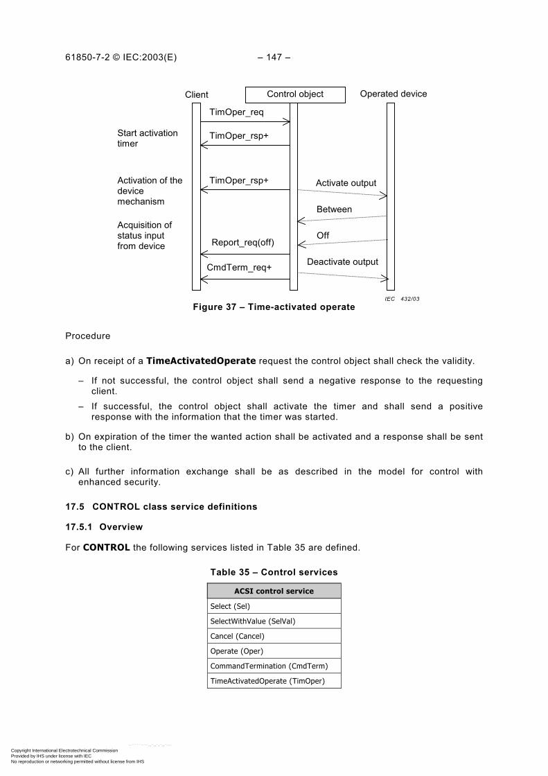
61850-7-2 © IEC:2003(E) – 147 –
Client Control object Operated device
TimOper_req
TimOper_rsp+ Activate output
Between
Off
Activation of thedevicemechanism
Report_req(off)
Acquisition ofstatus inputfrom device
Deactivate outputCmdTerm_req+
Start activationtimer
TimOper_rsp+
Figure 37 – Time-activated operate
Procedure
a) On receipt of a TimeActivatedOperate request the control object shall check the validity.
– If not successful, the control object shall send a negative response to the requestingclient.
– If successful, the control object shall activate the timer and shall send a positiveresponse with the information that the timer was started.
b) On expiration of the timer the wanted action shall be activated and a response shall be sentto the client.
c) All further information exchange shall be as described in the model for control withenhanced security.
17.5 CONTROL class service definitions
17.5.1 Overview
For CONTROL the following services listed in Table 35 are defined.
Table 35 – Control services
ACSI control service
Select (Sel)
SelectWithValue (SelVal)
Cancel (Cancel)
Operate (Oper)
CommandTermination (CmdTerm)
TimeActivatedOperate (TimOper)
IEC 432/03
Copyright International Electrotechnical Commission Provided by IHS under license with IEC
Not for ResaleNo reproduction or networking permitted without license from IHS
--``````-`-`,,`,,`,`,,`---

– 148 – 61850-7-2 IEC:2003(E)
17.5.2 Service parameter definition
The following service parameters shall be applied in the service definitions.
NOTE A pass-through parameter is a parameter that will not be interpreted by the service procedure. The valuereceived in a pass-through parameter is available for any server application. These parameters are outside thescope of this standard; for example, the interpretation of Test/noTest is outside the scope of this standard.
17.5.2.1 ControlObjectReference
The parameter ControlObjectReference shall contain the ObjectReference of the controllableDATA (defined in IEC 61850-7-4) to be accessed, for example Pos, which represents theDATA “Position”.
17.5.2.2 Value
The parameter Value shall include values for all implemented DataAttributes of a controllablecommon DATA class that are accessed by various control services.
NOTE Common DATA classes and their DataAttributes are defined in IEC 61850-7-3.
EXAMPLE For the case of an Operate request, the value may include the following parameters:– control value (on, off),– originator category (remote, station, bay...),– control sequence number.
17.5.2.3 T – control time-stamp
The parameter T shall be the time when the client sends the control request.
Table 36 – Control time-stamp definition
Control time-stamp type
Attribute name Attribute type Value/value range/explanation
T EntryTime
17.5.2.4 Test – test status [pass-through parameter]
The parameter Test shall define whether the information is caused by normal operation orby test.
Table 37 – Test status definition
Test status type
Attribute name Attribute type Value/value range/explanation
Test BOOLEAN no-test (FALSE) | test (TRUE)
17.5.2.5 Check – check condition
The parameter Check shall specify the kind of checks a control object shall perform beforeissuing the control operation if common DATA class is DPC (double-point control – seeIEC 61850-7-3).
Table 38 – Check condition definition
Check condition type
Attribute name Attribute type Value/value range/explanation
Check PACKED LIST
synchrocheck BOOLEAN TRUE means run synchrocheck
interlock-check BOOLEAN TRUE means run interlock-check
Copyright International Electrotechnical Commission Provided by IHS under license with IEC
Not for ResaleNo reproduction or networking permitted without license from IHS
--``````-`-`,,`,,`,`,,`---

61850-7-2 © IEC:2003(E) – 149 –
17.5.2.6 AddCause – additional cause diagnosis
The parameter AddCause shall identify the reason for failure in a negative control servicespecific response.
Table 39 – Additional cause diagnosis definition
Additional cause diagnosis type
Attribute name Attribute type Value/value range/explanation
AddCause ENUMERATION ServiceError typeBlocked-by-switching-hierarchySelect-failedInvalid-positionPosition-reachedParameter-change-in-executionStep-limitBlocked-by-ModeBlocked-by-processBlocked-by-interlockingBlocked-by-synchrocheckCommand-already-in-executionBlocked-by-health1-of-n-controlAbortion-by-cancelTime-limit-overAbortion-by-trip
The description of the values shall be as defined in Table 40.
Table 40 – AddCause semantic
Value Explanation
ServiceError type All errors as defined in Table 5
Blocked-by-switching-hierarchy Not successful since one of the downstream Loc switches like in CSWI has thevalue TRUE
Select-failed Cancelled due to an unsuccessful selection (select service)
Invalid-position Control action is aborted due to invalid switch position (Pos in XCBR or XSWI)
Position-reached Switch is already in the intended position (Pos in XCBR or XSWI)
Parameter-change-in-execution Control action is blocked due to running parameter change
Step-limit Control action is blocked, because tap changer has reached the limit (EndPosR orEndposL in YLTC)
Blocked-by-Mode Control action is blocked, because the LN (CSWI or XCBR/XSWI) is in a mode(Mod) which does not allow any switching
Blocked-by-process Control action is blocked due to some external even at process level that preventsa successful operation, for example, blocking indication (EEHealth in XCBR orXSWI)
Blocked-by-interlocking Control action is blocked due to interlocking of switching devices (in CILO attributeEnaOpn.stVal=“FALSE” or EnaCls.stVal=“FALSE”
Blocked-by-synchrocheck Control action with synchrocheck is aborted due to the exceeding of the time limitand missing synchronism condition
Command-already-in-execution Control service or cancel is rejected, because control action is already running
Blocked-by-health Control action is blocked due to some internal event that prevents a successfuloperation (Health)
1-of-n-control Control action is blocked, because another control action in a domain (forexample, substation) is already running (in any XCBR or XSWI, theDPC.stSeld=“TRUE”).
Abortion-by-cancel Control action is aborted due to cancel service
Time-limit-over Control action is terminated due to exceed of some time limit
Abortion-by-trip Control action is aborted due to a trip (PTRC with ACT.general=“TRUE”)
Copyright International Electrotechnical Commission Provided by IHS under license with IEC
Not for ResaleNo reproduction or networking permitted without license from IHS
--``````-`-`,,`,,`,`,,`---

– 150 – 61850-7-2 IEC:2003(E)
17.5.2.7 TimOperRsp – TimeActivatedOperate response
This parameter TimOperRsp shall specify the details of the positive response on the serviceTimeActivatedOperate
Table 41 – TimeActivatedOperate response definition
TimeActivatedOperate response type
Attribute name Attribute type Value/value range/explanation
TimOperRsp ENUMERATED timer-activated | command-executed
17.5.3 Service specification
17.5.3.1 General
The services operate on several DataAttributes defined in common data classes ofIEC 61850-7-3. Mainly the following DataAttributes defined in IEC 61850-7-3 are involvedin control services:
– ctlVal (the value to be controlled);
– operTm (the time when to operate for the TimeActivatedOperate service);
– origin (indicating who issued the service);
– ctlNum (control sequence number).
The last three DataAttributes, if available, shall be set before the control services of thisclause can be issued on the DataAttribute CtlVal.
NOTE 1 The SCSM defines the subset of service parameters in the response service primitives. A communicationstack that allows the client to assign a response to the relating request may not support all the service parametersthat were also transmitted in the request.
NOTE 2 The additional cause diagnosis is a service parameter that is only transmitted in the response serviceprimitives. The SCSM defines how this service parameter is included in the response PDU.
17.5.3.2 Select (Sel)
The Select service shall define the following service parameters.
Parameter name
Request
ControlObjectReference
Response+
ControlObjectReference
Response–
ControlObjectReference
NOTE The service parameters are defined in 17.5.2.
Copyright International Electrotechnical Commission Provided by IHS under license with IEC
Not for ResaleNo reproduction or networking permitted without license from IHS
--``````-`-`,,`,,`,`,,`---

61850-7-2 © IEC:2003(E) – 151 –
17.5.3.3 SelectWithValue (SelVal)
The SelectWithValue service shall define the following service parameters.
Parameter name
Request
ControlObjectReference
Value
T
Test
Check
Response+
ControlObjectReference
Value
T
Test
Response–
ControlObjectReference
Value
T
Test
AddCause
NOTE The service parameters are defined in 17.5.2.
17.5.3.4 Cancel
The Cancel service shall be used for the de-selection.
Parameter name
Request
ControlObjectReference
T
Test
Response+
ControlObjectReference
T
Test
Response–
ControlObjectReference
T
Test
AddCause
NOTE The service parameters are defined in 17.5.2.
Copyright International Electrotechnical Commission Provided by IHS under license with IEC
Not for ResaleNo reproduction or networking permitted without license from IHS
--``````-`-`,,`,,`,`,,`---

– 152 – 61850-7-2 IEC:2003(E)
17.5.3.5 Operate (Oper)
The Operate service shall define the following service parameters.
Parameter name
Request
ControlObjectReference
Value
T
Test
Check
Response+
ControlObjectReference
Value
T
Test
Response–
ControlObjectReference
Value
T
Test
AddCause
NOTE The service parameters are defined in 17.5.2.
17.5.3.6 CommandTermination (CmdTerm)
The CommandTermination service shall define the following service parameters.
Parameter name
Request+
ControlObjectReference
T
Test
Request–
ControlObjectReference
T
Test
AddCause
NOTE The service parameters are defined in 17.5.2.
17.5.3.7 TimeActivatedOperate (TimOper)
The TimeActivatedOperate service shall define the following service parameters.
Copyright International Electrotechnical Commission Provided by IHS under license with IEC
Not for ResaleNo reproduction or networking permitted without license from IHS
--``````-`-`,,`,,`,`,,`---

61850-7-2 © IEC:2003(E) – 153 –
Parameter name
Request
ControlObjectReference
Value
T
Test
Check
Response+
ControlObjectReference
Value
T
Test
TimOperRsp
Response–
ControlObjectReference
Value
T
Test
AddCause
NOTE The service parameters are defined in 17.5.2.
Copyright International Electrotechnical Commission Provided by IHS under license with IEC
Not for ResaleNo reproduction or networking permitted without license from IHS
--``````-`-`,,`,,`,`,,`---

– 154 – 61850-7-2 IEC:2003(E)
18 Time and time-synchronization model
18.1 General
The time and time-synchronization model shall provide the UTC synchronized time toapplications located in server and client substation IEDs. The components of the time andtime-synchronization model are depicted in Figure 38.
Time server/IEC 61850 server
Time server/IEC 61850 serverIEC 61850
Client/serverIEC 61850
Client/server
Information fromexternal source
Time synchronization
IEC 61850 SCSM
IEC 61850-7-2
Time stamp semantic
Time stamp presentation
Time stamp semantic
IEC 61850 SCSM
Master UTC time (externally synchronized;
epoch 1970-01-01)
UTC synchronized time (epoch 1970-01-01)
Figure 38 – Time model and time synchronization (principle)
The model shall comprise
– the external information required by the time master from an external source tosynchronize other substation server or client IEDs (see 18.2);
– time server providing the source for the substation internal time synchronization andsource for time stamping (in case the time server is implemented together with anIEC 61850 client/server in one physical device);
– time synchronization protocol providing time synchronization with other IEDs. Timesynchronization shall meet the requirements of IEC 61850-5; the specification of timesynchronization is defined in the SCSMs (for example, SNTP for IEC 61850-8-1);
– the time stamp semantics used for information exchange of the ACSI (see 5.5.3.6);
– the presentation of the time stamps according to the chosen SCSM;
– the server and clients that need substation-wide synchronized time.
18.2 External information
External information required for the time and time synchronization model shall provide thefollowing.a) Received external time
– synchronized time to some known level of accuracy;– elapsed number of seconds since Epoch. If this count of seconds includes the leap
seconds that have occurred since the epoch then the time produced by this time servershall have the LeapSecondsKnown quality attribute set to true, otherwise set to false.
b) Epoch (for example, GPS 6.1.1980).
IEC 433/03
Copyright International Electrotechnical Commission Provided by IHS under license with IEC
Not for ResaleNo reproduction or networking permitted without license from IHS
--``````-`-`,,`,,`,`,,`---
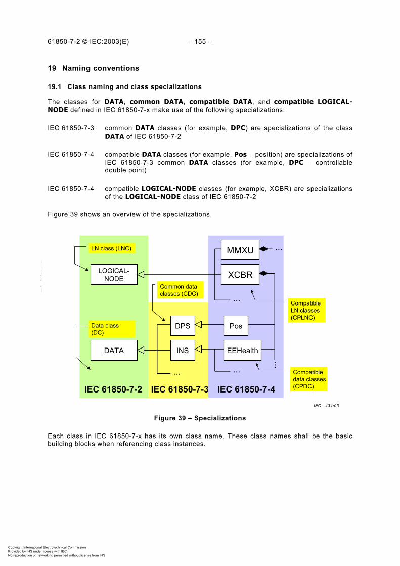
61850-7-2 © IEC:2003(E) – 155 –
19 Naming conventions
19.1 Class naming and class specializations
The classes for DATA, common DATA, compatible DATA, and compatible LOGICAL-NODE defined in IEC 61850-7-x make use of the following specializations:
IEC 61850-7-3 common DATA classes (for example, DPC) are specializations of the classDATA of IEC 61850-7-2
IEC 61850-7-4 compatible DATA classes (for example, Pos – position) are specializations ofIEC 61850-7-3 common DATA classes (for example, DPC – controllabledouble point)
IEC 61850-7-4 compatible LOGICAL-NODE classes (for example, XCBR) are specializationsof the LOGICAL-NODE class of IEC 61850-7-2
Figure 39 shows an overview of the specializations.
LOGICAL-NODE
DATA
DPS
EEHealth
Pos
INS
...
XCBR
MMXU
...
IEC 61850-7-2 IEC 61850-7-3 IEC 61850-7-4
... ...
Compatibledata classes(CPDC)
Common dataclasses (CDC)
CompatibleLN classes(CPLNC)
...
Data class(DC)
LN class (LNC)
Figure 39 – Specializations
Each class in IEC 61850-7-x has its own class name. These class names shall be the basicbuilding blocks when referencing class instances.
IEC 434/03
Copyright International Electrotechnical Commission Provided by IHS under license with IEC
Not for ResaleNo reproduction or networking permitted without license from IHS
--``````-`-`,,`,,`,`,,`---
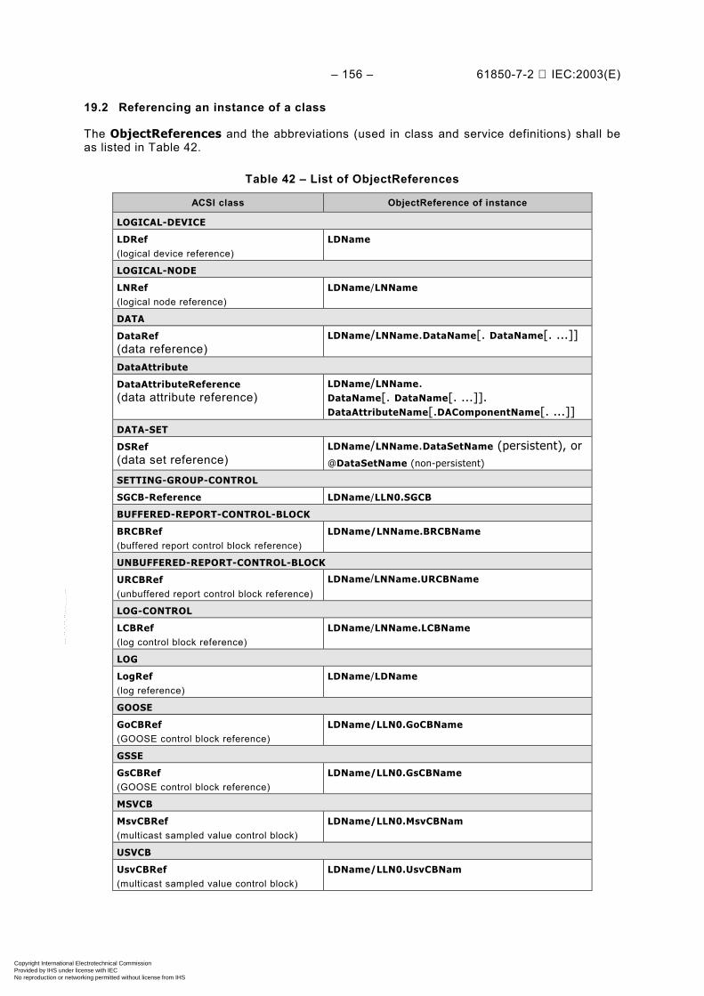
– 156 – 61850-7-2 IEC:2003(E)
19.2 Referencing an instance of a class
The ObjectReferences and the abbreviations (used in class and service definitions) shall beas listed in Table 42.
Table 42 – List of ObjectReferences
ACSI class ObjectReference of instance
LOGICAL-DEVICE
LDRef(logical device reference)
LDName
LOGICAL-NODE
LNRef(logical node reference)
LDName/LNName
DATA
DataRef(data reference)
LDName/LNName.DataName[. DataName[. ...]]
DataAttribute
DataAttributeReference(data attribute reference)
LDName/LNName.DataName[. DataName[. ...]].DataAttributeName[.DAComponentName[. ...]]
DATA-SET
DSRef(data set reference)
LDName/LNName.DataSetName (persistent), or@DataSetName (non-persistent)
SETTING-GROUP-CONTROL
SGCB-Reference LDName/LLN0.SGCB
BUFFERED-REPORT-CONTROL-BLOCK
BRCBRef(buffered report control block reference)
LDName/LNName.BRCBName
UNBUFFERED-REPORT-CONTROL-BLOCK
URCBRef(unbuffered report control block reference)
LDName/LNName.URCBName
LOG-CONTROL
LCBRef(log control block reference)
LDName/LNName.LCBName
LOG
LogRef(log reference)
LDName/LDName
GOOSE
GoCBRef(GOOSE control block reference)
LDName/LLN0.GoCBName
GSSE
GsCBRef(GOOSE control block reference)
LDName/LLN0.GsCBName
MSVCB
MsvCBRef(multicast sampled value control block)
LDName/LLN0.MsvCBNam
USVCB
UsvCBRef(multicast sampled value control block)
LDName/LLN0.UsvCBNam
Copyright International Electrotechnical Commission Provided by IHS under license with IEC
Not for ResaleNo reproduction or networking permitted without license from IHS
--``````-`-`,,`,,`,`,,`---
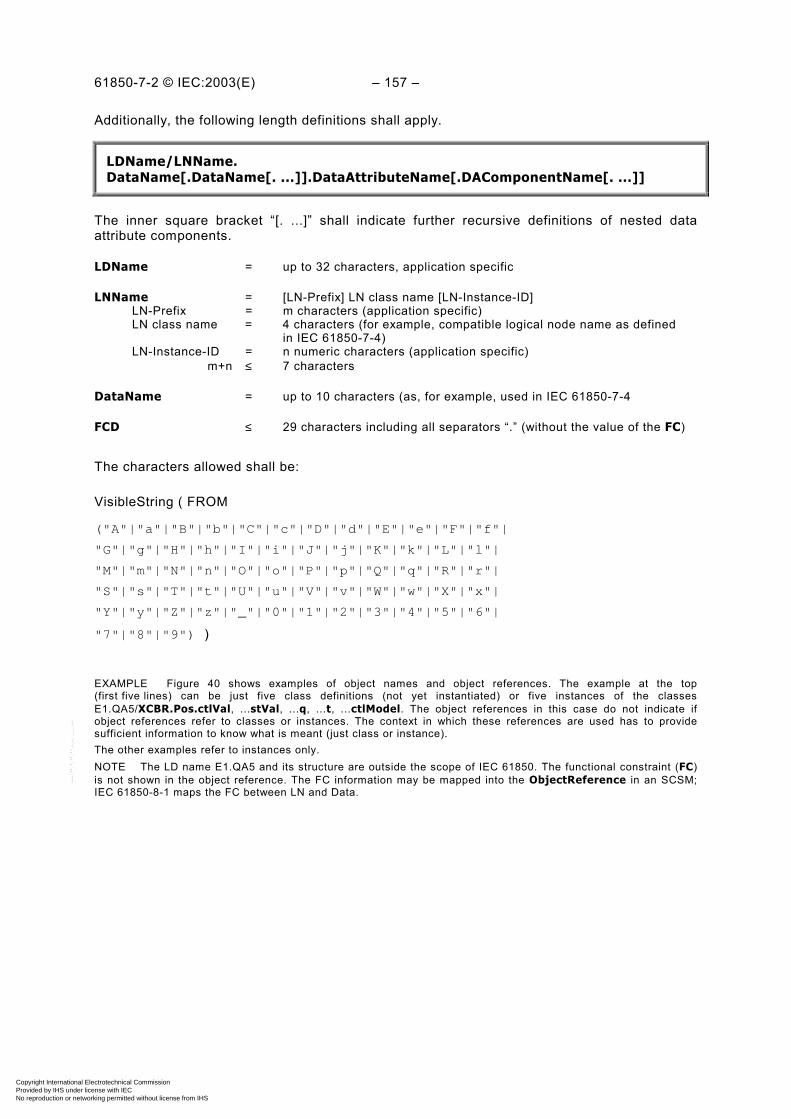
61850-7-2 © IEC:2003(E) – 157 –
Additionally, the following length definitions shall apply.
LDName/LNName.DataName[.DataName[. ...]].DataAttributeName[.DAComponentName[. ...]]
The inner square bracket “[. ...]” shall indicate further recursive definitions of nested dataattribute components.
LDName = up to 32 characters, application specific
LNName = [LN-Prefix] LN class name [LN-Instance-ID] LN-Prefix = m characters (application specific) LN class name = 4 characters (for example, compatible logical node name as defined in IEC 61850-7-4) LN-Instance-ID = n numeric characters (application specific) m+n ≤ 7 characters
DataName = up to 10 characters (as, for example, used in IEC 61850-7-4
FCD ≤ 29 characters including all separators “.” (without the value of the FC)
The characters allowed shall be:
VisibleString ( FROM
("A"|"a"|"B"|"b"|"C"|"c"|"D"|"d"|"E"|"e"|"F"|"f"|
"G"|"g"|"H"|"h"|"I"|"i"|"J"|"j"|"K"|"k"|"L"|"l"|
"M"|"m"|"N"|"n"|"O"|"o"|"P"|"p"|"Q"|"q"|"R"|"r"|
"S"|"s"|"T"|"t"|"U"|"u"|"V"|"v"|"W"|"w"|"X"|"x"|
"Y"|"y"|"Z"|"z"|"_"|"0"|"1"|"2"|"3"|"4"|"5"|"6"|
"7"|"8"|"9") )
EXAMPLE Figure 40 shows examples of object names and object references. The example at the top(first five lines) can be just five class definitions (not yet instantiated) or five instances of the classesE1.QA5/XCBR.Pos.ctlVal, ...stVal, ...q, ...t, ...ctlModel. The object references in this case do not indicate ifobject references refer to classes or instances. The context in which these references are used has to providesufficient information to know what is meant (just class or instance).The other examples refer to instances only.NOTE The LD name E1.QA5 and its structure are outside the scope of IEC 61850. The functional constraint (FC)is not shown in the object reference. The FC information may be mapped into the ObjectReference in an SCSM;IEC 61850-8-1 maps the FC between LN and Data.
Copyright International Electrotechnical Commission Provided by IHS under license with IEC
Not for ResaleNo reproduction or networking permitted without license from IHS
--``````-`-`,,`,,`,`,,`---
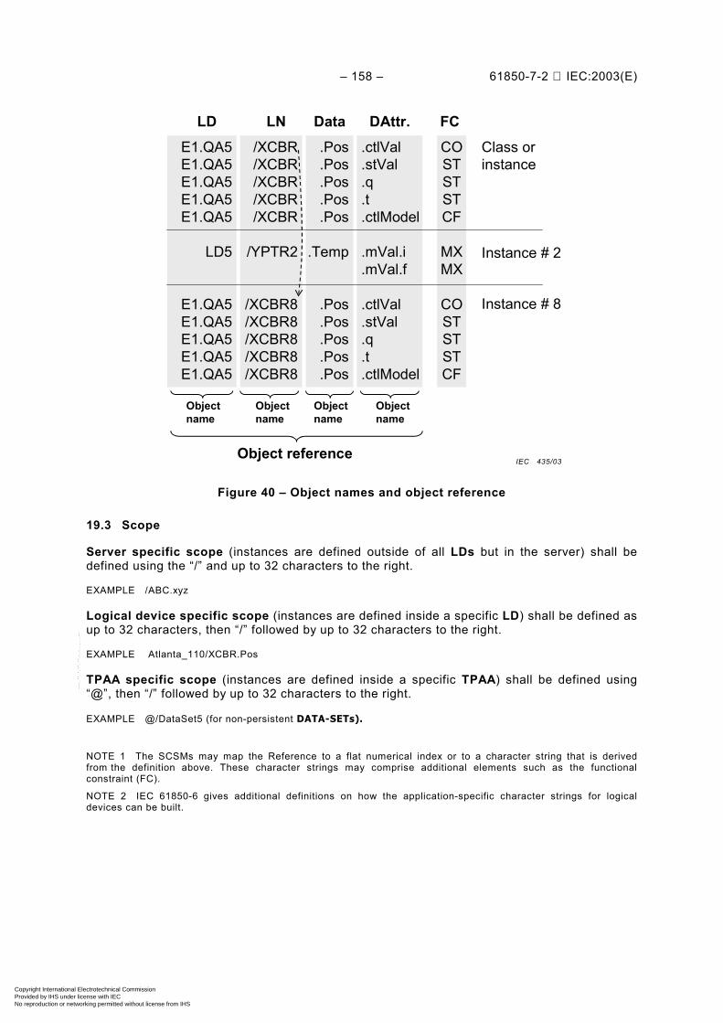
– 158 – 61850-7-2 IEC:2003(E)
LD LNE1.QA5E1.QA5E1.QA5E1.QA5E1.QA5
LD5
E1.QA5E1.QA5E1.QA5E1.QA5E1.QA5
/XCBR/XCBR/XCBR/XCBR/XCBR
/YPTR2
/XCBR8/XCBR8/XCBR8/XCBR8/XCBR8
Data.Pos.Pos.Pos.Pos.Pos
.Temp
.Pos
.Pos
.Pos
.Pos
.Pos
DAttr..ctlVal.stVal.q.t.ctlModel
.mVal.i
.mVal.f
.ctlVal
.stVal
.q
.t
.ctlModel
COSTSTSTCF
MXMX
COSTSTSTCF
FCClass orinstance
Instance # 8
Instance # 2
Object reference
Objectname
Objectname
Objectname
Objectname
Figure 40 – Object names and object reference
19.3 Scope
Server specific scope (instances are defined outside of all LDs but in the server) shall bedefined using the “/” and up to 32 characters to the right.
EXAMPLE /ABC.xyz
Logical device specific scope (instances are defined inside a specific LD) shall be defined asup to 32 characters, then “/” followed by up to 32 characters to the right.
EXAMPLE Atlanta_110/XCBR.Pos
TPAA specific scope (instances are defined inside a specific TPAA) shall be defined using“@”, then “/” followed by up to 32 characters to the right.
EXAMPLE @/DataSet5 (for non-persistent DATA-SETs).
NOTE 1 The SCSMs may map the Reference to a flat numerical index or to a character string that is derivedfrom the definition above. These character strings may comprise additional elements such as the functionalconstraint (FC).
NOTE 2 IEC 61850-6 gives additional definitions on how the application-specific character strings for logicaldevices can be built.
IEC 435/03
Copyright International Electrotechnical Commission Provided by IHS under license with IEC
Not for ResaleNo reproduction or networking permitted without license from IHS
--``````-`-`,,`,,`,`,,`---
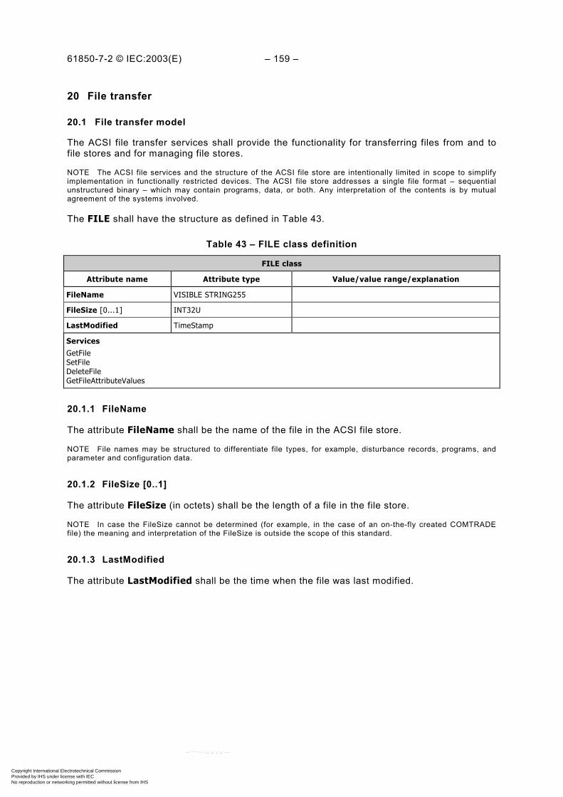
61850-7-2 © IEC:2003(E) – 159 –
20 File transfer
20.1 File transfer model
The ACSI file transfer services shall provide the functionality for transferring files from and tofile stores and for managing file stores.
NOTE The ACSI file services and the structure of the ACSI file store are intentionally limited in scope to simplifyimplementation in functionally restricted devices. The ACSI file store addresses a single file format – sequentialunstructured binary – which may contain programs, data, or both. Any interpretation of the contents is by mutualagreement of the systems involved.
The FILE shall have the structure as defined in Table 43.
Table 43 – FILE class definition
FILE class
Attribute name Attribute type Value/value range/explanation
FileName VISIBLE STRING255
FileSize [0...1] INT32U
LastModified TimeStamp
ServicesGetFileSetFileDeleteFileGetFileAttributeValues
20.1.1 FileName
The attribute FileName shall be the name of the file in the ACSI file store.
NOTE File names may be structured to differentiate file types, for example, disturbance records, programs, andparameter and configuration data.
20.1.2 FileSize [0..1]
The attribute FileSize (in octets) shall be the length of a file in the file store.
NOTE In case the FileSize cannot be determined (for example, in the case of an on-the-fly created COMTRADEfile) the meaning and interpretation of the FileSize is outside the scope of this standard.
20.1.3 LastModified
The attribute LastModified shall be the time when the file was last modified.
Copyright International Electrotechnical Commission Provided by IHS under license with IEC
Not for ResaleNo reproduction or networking permitted without license from IHS
--``````-`-`,,`,,`,`,,`---
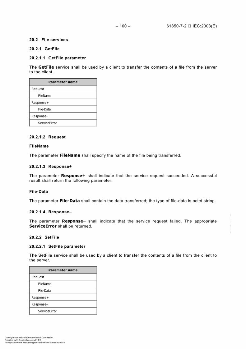
– 160 – 61850-7-2 IEC:2003(E)
20.2 File services
20.2.1 GetFile
20.2.1.1 GetFile parameter
The GetFile service shall be used by a client to transfer the contents of a file from the serverto the client.
Parameter name
Request
FileName
Response+
File-Data
Response–
ServiceError
20.2.1.2 Request
FileName
The parameter FileName shall specify the name of the file being transferred.
20.2.1.3 Response+
The parameter Response+ shall indicate that the service request succeeded. A successfulresult shall return the following parameter.
File-Data
The parameter File-Data shall contain the data transferred; the type of file-data is octet string.
20.2.1.4 Response–
The parameter Response– shall indicate that the service request failed. The appropriateServiceError shall be returned.
20.2.2 SetFile
20.2.2.1 SetFile parameter
The SetFile service shall be used by a client to transfer the contents of a file from the client tothe server.
Parameter name
Request
FileName
File-Data
Response+
Response–
ServiceError
Copyright International Electrotechnical Commission Provided by IHS under license with IEC
Not for ResaleNo reproduction or networking permitted without license from IHS
--``````-`-`,,`,,`,`,,`---

61850-7-2 © IEC:2003(E) – 161 –
20.2.2.2 Request
20.2.2.2.1 FileName
The parameter FileName shall specify the name of the file being transferred.
20.2.2.2.2 File-Data
The parameter File-Data shall contain the data transferred; the type of file-data is octet string.
20.2.2.3 Response+
The parameter Response+ shall indicate that the service request succeeded.
20.2.2.4 Response–
The parameter Response– shall indicate that the service request failed. The appropriateServiceError shall be returned.
20.2.3 DeleteFile
20.2.3.1 DeleteFile parameter
The FileDelete service shall be used by a client to delete a file in the file store of a server.
Parameter name
Request
FileName
Response+
Response–
ServiceError
20.2.3.2 Request
FileName
The parameter FileName shall specify the name of the file being deleted.
20.2.3.3 Response+
The parameter Response+ shall indicate that the service request succeeded.
20.2.3.4 Response–
The parameter Response– shall indicate that the service request failed. The appropriateServiceError shall be returned.
Copyright International Electrotechnical Commission Provided by IHS under license with IEC
Not for ResaleNo reproduction or networking permitted without license from IHS
--``````-`-`,,`,,`,`,,`---

– 162 – 61850-7-2 IEC:2003(E)
20.2.4 GetFileAttributeValues
20.2.4.1 GetFileAttributeValues parameter
The GetFileAttributeValues service shall be used by a client to obtain the name andattributes of a specific file in the server's file store.
Parameter name
Request
FileName
Response+
FileName
FileAttribute [1..n]
Response–
ServiceError
20.2.4.2 Request
FileName
The parameter FileName shall, when present, specify the name of the file whose attributes arerequested to be returned to the client.
20.2.4.3 Response+
The parameter Response+ shall indicate that the service request succeeded. A successfulresult shall return the following parameters.
20.2.4.3.1 FileName
The parameter FileName shall provide the name of the file whose attributes are returned.
20.2.4.3.2 FileAttribute [1..n]
The parameter FileAttribute shall contain attribute information describing the selected file.This information consists of the size of the file and time of last modification.
20.2.4.4 Response–
The parameter Response– shall indicate that the service request failed. The appropriateServiceError shall be returned.
Copyright International Electrotechnical Commission Provided by IHS under license with IEC
Not for ResaleNo reproduction or networking permitted without license from IHS
--``````-`-`,,`,,`,`,,`---

61850-7-2 © IEC:2003(E) – 163 –
Annex A (normative)
ACSI conformance statement
A.1 General
The following ACSI conformance statements shall be used to provide an overview and detailsabout a device claiming conformance with ACSI:
– ACSI basic conformance statement
– ACSI models conformance statement
– ACSI service conformance statement
to specify the communication features mapped to an SCSM.
NOTE 1 The conformance statements of this annex are abstract in the sense that the ACSI models and theirservices are mapped to application layer models, services, and protocols. Additional details on the conformance aredefined in the SCSM.
NOTE 2 For several features the conformance requirement is implicitly defined with the common data classcontained in IEC 61850-7-3 and the compatible LOGICAL-NODE classes and DATA classes contained inIEC 61850-7-4, for example, a TrgOp (trigger option) of the value qchg (quality change) of DataAttribute requiresthe support of the TrgOp (trigger option) qchg of the BRCB or URCB.
A.2 ACSI basic conformance statement
The basic conformance statement shall be as defined in Table A.1.
Table A.1 – Basic conformance statement
Client/subscriber
Server/publisher
Value/comments
Client-server roles
B11 Server side (of TWO-PARTY-APPLICATION-ASSOCIATION)
– c1
B12 Client side of (TWO-PARTY-APPLICATION-ASSOCIATION)
c1 –
SCSMs supported
B21 SCSM: IEC 61850-8-1 usedB22 SCSM: IEC 61850-9-1 usedB23 SCSM: IEC 61850-9-2 usedB24 SCSM: other
Generic substation event model (GSE)
B31 Publisher side – O
B32 Subscriber side O –
Transmission of sampled value model (SVC)
B41 Publisher side – O
B42 Subscriber side O –c1 – shall be ‘M’ if support for LOGICAL-DEVICE model has been declared.
O – Optional
M – Mandatory
Copyright International Electrotechnical Commission Provided by IHS under license with IEC
Not for ResaleNo reproduction or networking permitted without license from IHS
--``````-`-`,,`,,`,`,,`---
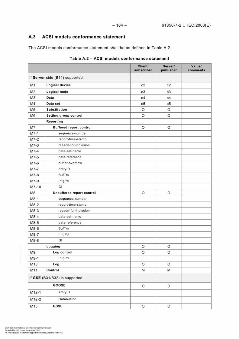
– 164 – 61850-7-2 IEC:2003(E)
A.3 ACSI models conformance statement
The ACSI models conformance statement shall be as defined in Table A.2.
Table A.2 – ACSI models conformance statement
Client/subscriber
Server/publisher
Value/comments
If Server side (B11) supported
M1 Logical device c2 c2
M2 Logical node c3 c3M3 Data c4 c4M4 Data set c5 c5M5 Substitution O OM6 Setting group control O O
Reporting
M7 Buffered report control O OM7-1 sequence-number
M7-2 report-time-stamp
M7-3 reason-for-inclusion
M7-4 data-set-name
M7-5 data-reference
M7-6 buffer-overflow
M7-7 entryID
M7-8 BufTm
M7-9 IntgPd
M7-10 GI
M8 Unbuffered report control O OM8-1 sequence-number
M8-2 report-time-stamp
M8-3 reason-for-inclusion
M8-4 data-set-name
M8-5 data-reference
M8-6 BufTm
M8-7 IntgPd
M8-8 GI
Logging O OM9 Log control O OM9-1 IntgPd
M10 Log O OM11 Control M M
If GSE (B31/B32) is supported
GOOSE O O
M12-1 entryID
M12-2 DataRefInc
M13 GSSE O O
Copyright International Electrotechnical Commission Provided by IHS under license with IEC
Not for ResaleNo reproduction or networking permitted without license from IHS
--``````-`-`,,`,,`,`,,`---
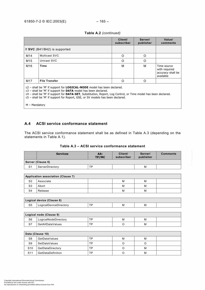
61850-7-2 © IEC:2003(E) – 165 –
Table A.2 (continued)
Client/subscriber
Server/publisher
Value/comments
If SVC (B41/B42) is supported
M14 Multicast SVC O OM15 Unicast SVC O OM16 Time M M Time source
with requiredaccuracy shall beavailable
M17 File Transfer O O
c2 – shall be ‘M’ if support for LOGICAL-NODE model has been declared.c3 – shall be ‘M’ if support for DATA model has been declared.c4 – shall be ‘M’ if support for DATA-SET, Substitution, Report, Log Control, or Time model has been declared.c5 – shall be ‘M’ if support for Report, GSE, or SV models has been declared.
M – Mandatory
A.4 ACSI service conformance statement
The ACSI service conformance statement shall be as defined in Table A.3 (depending on thestatements in Table A.1).
Table A.3 – ACSI service conformance statement
Services AA:TP/MC
Client/subscriber
Server/publisher
Comments
Server (Clause 6)S1 ServerDirectory TP M
Application association (Clause 7)S2 Associate M M
S3 Abort M M
S4 Release M M
Logical device (Clause 8)S5 LogicalDeviceDirectory TP M M
Logical node (Clause 9)S6 LogicalNodeDirectory TP M M
S7 GetAllDataValues TP O M
Data (Clause 10)S8 GetDataValues TP M M
S9 SetDataValues TP O O
S10 GetDataDirectory TP O M
S11 GetDataDefinition TP O M
Copyright International Electrotechnical Commission Provided by IHS under license with IEC
Not for ResaleNo reproduction or networking permitted without license from IHS
--``````-`-`,,`,,`,`,,`---

– 166 – 61850-7-2 IEC:2003(E)
Table A.3 (continued)
Services AA:TP/MC
Client/subscriber
Server/publisher
Comments
Data set (Clause 11)S12 GetDataSetValues TP O M
S13 SetDataSetValues TP O O
S14 CreateDataSet TP O O
S15 DeleteDataSet TP O O
S16 GetDataSetDirectory TP O O
Substitution (Clause 12)S17 SetDataValues TP M M
Setting group control (Clause 13)S18 SelectActiveSG TP O O
S19 SelectEditSG TP O O
S20 SetSGValues TP O O
S21 ConfirmEditSGValues TP O O
S22 GetSGValues TP O O
S23 GetSGCBValues TP O O
Reporting (Clause 14)Buffered report control block (BRCB)
S24 Report TP c6 c6
S24-1 data-change (dchg)
S24-2 qchg-change (qchg)
S24-3 data-update (dupd)
S25 GetBRCBValues TP c6 c6
S26 SetBRCBValues TP c6 c6
Unbuffered report control block (URCB)
S27 Report TP c6 c6
S27-1 data-change (dchg)
S27-2 qchg-change (qchg)
S27-3 data-update (dupd)
S28 GetURCBValues TP c6 c6
S29 SetURCBValues TP c6 c6
c6 – shall declare support for at least one (BRCB or URCB).
Logging (Clause 14)Log control block
S30 GetLCBValues TP M M
S31 SetLCBValues TP O M
Log
S32 QueryLogByTime TP c7 M
S33 QueryLogAfter TP c7 M
S34 GetLogStatusValues TP M M
c7 – shall declare support for at least one (QueryLogByTime or QueryLogAfter).
Copyright International Electrotechnical Commission Provided by IHS under license with IEC
Not for ResaleNo reproduction or networking permitted without license from IHS
--``````-`-`,,`,,`,`,,`---
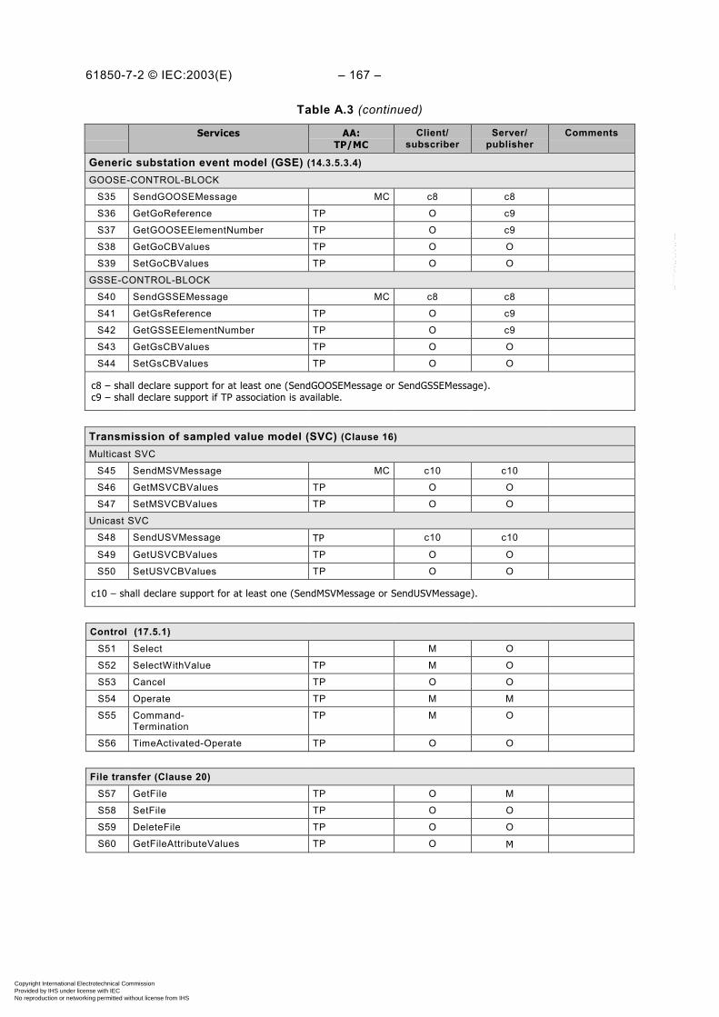
61850-7-2 © IEC:2003(E) – 167 –
Table A.3 (continued)
Services AA:TP/MC
Client/subscriber
Server/publisher
Comments
Generic substation event model (GSE) (14.3.5.3.4)GOOSE-CONTROL-BLOCK
S35 SendGOOSEMessage MC c8 c8
S36 GetGoReference TP O c9
S37 GetGOOSEElementNumber TP O c9
S38 GetGoCBValues TP O O
S39 SetGoCBValues TP O O
GSSE-CONTROL-BLOCK
S40 SendGSSEMessage MC c8 c8
S41 GetGsReference TP O c9
S42 GetGSSEElementNumber TP O c9
S43 GetGsCBValues TP O O
S44 SetGsCBValues TP O O
c8 – shall declare support for at least one (SendGOOSEMessage or SendGSSEMessage).c9 – shall declare support if TP association is available.
Transmission of sampled value model (SVC) (Clause 16)Multicast SVC
S45 SendMSVMessage MC c10 c10
S46 GetMSVCBValues TP O O
S47 SetMSVCBValues TP O O
Unicast SVC
S48 SendUSVMessage TP c10 c10
S49 GetUSVCBValues TP O O
S50 SetUSVCBValues TP O O
c10 – shall declare support for at least one (SendMSVMessage or SendUSVMessage).
Control (17.5.1)S51 Select M O
S52 SelectWithValue TP M O
S53 Cancel TP O O
S54 Operate TP M M
S55 Command-Termination
TP M O
S56 TimeActivated-Operate TP O O
File transfer (Clause 20)S57 GetFile TP O M
S58 SetFile TP O O
S59 DeleteFile TP O O
S60 GetFileAttributeValues TP O M
Copyright International Electrotechnical Commission Provided by IHS under license with IEC
Not for ResaleNo reproduction or networking permitted without license from IHS
--``````-`-`,,`,,`,`,,`---
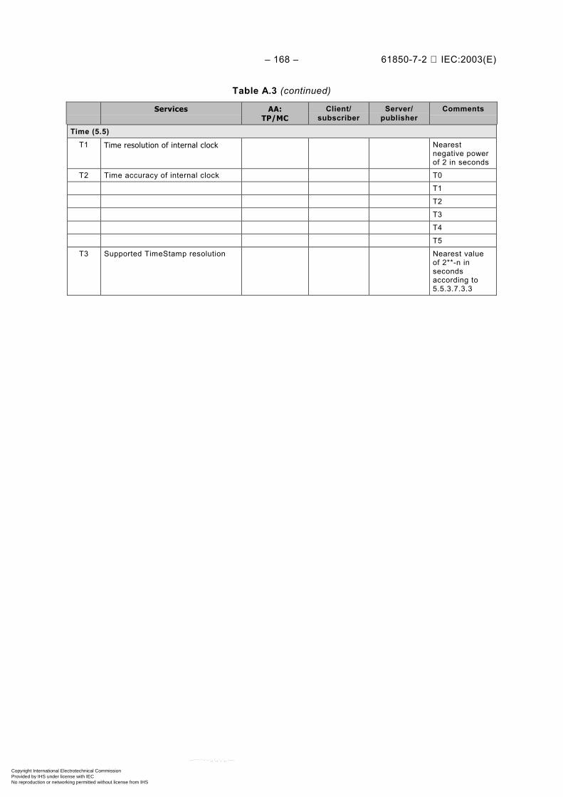
– 168 – 61850-7-2 IEC:2003(E)
Table A.3 (continued)
Services AA:TP/MC
Client/subscriber
Server/publisher
Comments
Time (5.5)T1 Time resolution of internal clock Nearest
negative powerof 2 in seconds
T2 Time accuracy of internal clock T0
T1
T2
T3
T4
T5
T3 Supported TimeStamp resolution Nearest valueof 2**-n insecondsaccording to5.5.3.7.3.3
Copyright International Electrotechnical Commission Provided by IHS under license with IEC
Not for ResaleNo reproduction or networking permitted without license from IHS
--``````-`-`,,`,,`,`,,`---

61850-7-2 © IEC:2003(E) – 169 –
Bibliography
IEEE-SA TR 1550-1999 – Utility Communications Architecture (UCA™) Version 2 4.
———————4 UCA™ is a registered trade mark of EPRI, Palo Alto (USA).
Copyright International Electrotechnical Commission Provided by IHS under license with IEC
Not for ResaleNo reproduction or networking permitted without license from IHS
--``````-`-`,,`,,`,`,,`---
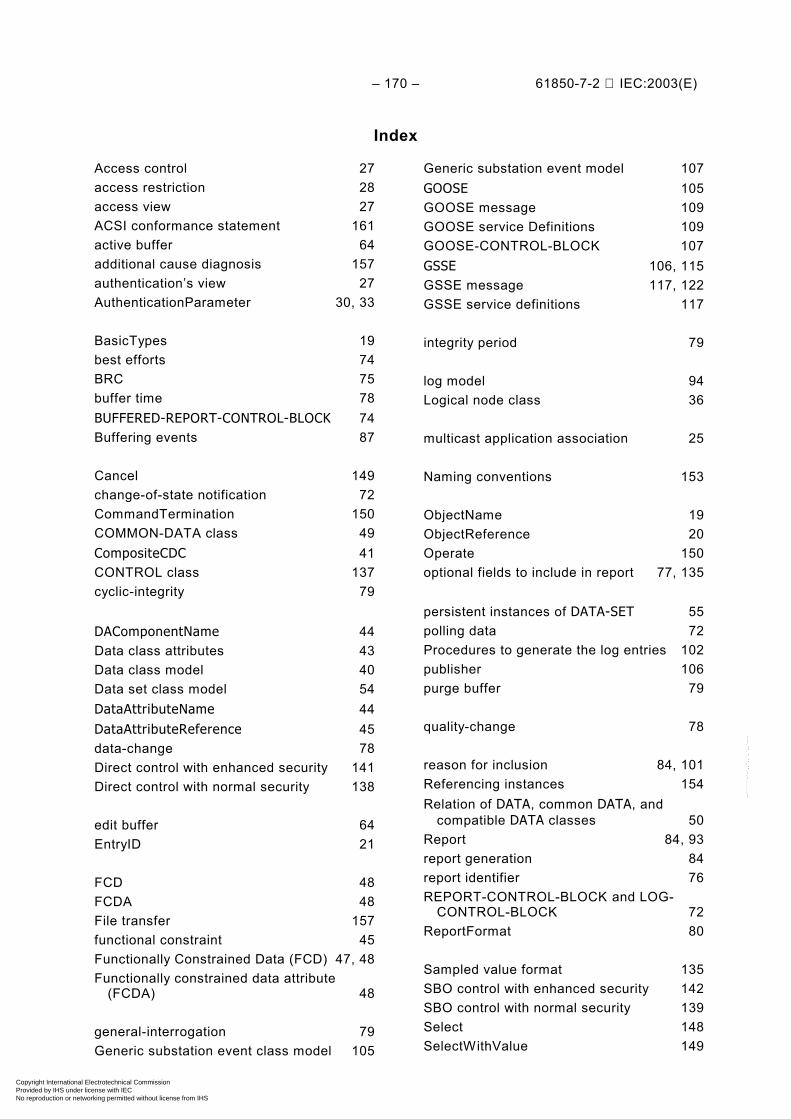
– 170 – 61850-7-2 IEC:2003(E)
Index
Access control 27access restriction 28access view 27ACSI conformance statement 161active buffer 64additional cause diagnosis 157authentication’s view 27AuthenticationParameter 30, 33
BasicTypes 19best efforts 74BRC 75buffer time 78BUFFERED-REPORT-CONTROL-BLOCK 74Buffering events 87
Cancel 149change-of-state notification 72CommandTermination 150COMMON-DATA class 49CompositeCDC 41CONTROL class 137cyclic-integrity 79
DAComponentName 44Data class attributes 43Data class model 40Data set class model 54DataAttributeName 44DataAttributeReference 45data-change 78Direct control with enhanced security 141Direct control with normal security 138
edit buffer 64EntryID 21
FCD 48FCDA 48File transfer 157functional constraint 45Functionally Constrained Data (FCD) 47, 48Functionally constrained data attribute
(FCDA) 48
general-interrogation 79Generic substation event class model 105
Generic substation event model 107GOOSE 105GOOSE message 109GOOSE service Definitions 109GOOSE-CONTROL-BLOCK 107GSSE 106, 115GSSE message 117, 122GSSE service definitions 117
integrity period 79
log model 94Logical node class 36
multicast application association 25
Naming conventions 153
ObjectName 19ObjectReference 20Operate 150optional fields to include in report 77, 135
persistent instances of DATA-SET 55polling data 72Procedures to generate the log entries 102publisher 106purge buffer 79
quality-change 78
reason for inclusion 84, 101Referencing instances 154Relation of DATA, common DATA, and
compatible DATA classes 50Report 84, 93report generation 84report identifier 76REPORT-CONTROL-BLOCK and LOG-
CONTROL-BLOCK 72ReportFormat 80
Sampled value format 135SBO control with enhanced security 142SBO control with normal security 139Select 148SelectWithValue 149
Copyright International Electrotechnical Commission Provided by IHS under license with IEC
Not for ResaleNo reproduction or networking permitted without license from IHS
--``````-`-`,,`,,`,`,,`---

61850-7-2 © IEC:2003(E) – 171 –
sequence-of-event 72sequence-of-events 72, 94ServiceError 20setting group 63SETTING-GROUP-CONTROL-BLOCK 63SimpleCDC 41SOE 94subscribers 106Substitution model 61
Time activated control 144Time and time synchronization 152Time sequence order of reports 87Time stamp type 21TimeAccuracy 23TimeActivatedOperate 150
TimeStamp type 21Transmission of sampled value 123Transmission of sampled values using
multicast 124TrgOp and Reporting 48trigger option 47trigger options enabled 78TriggerConditions 47TriggerConditions type 23two-party application association 25
UNBUFFERED-REPORT-CONTROL-BLOCK 74, 92
UTC 21
view 27
_____________
Copyright International Electrotechnical Commission Provided by IHS under license with IEC
Not for ResaleNo reproduction or networking permitted without license from IHS
--``````-`-`,,`,,`,`,,`---

Copyright International Electrotechnical Commission Provided by IHS under license with IEC
Not for ResaleNo reproduction or networking permitted without license from IHS
--``````-`-`,,`,,`,`,,`---

Standards Survey
The IEC would like to offer you the best quality standards possible. To make sure that wecontinue to meet your needs, your feedback is essential. Would you please take a minuteto answer the questions overleaf and fax them to us at +41 22 919 03 00 or mail them tothe address below. Thank you!
Customer Service Centre (CSC)
International Electrotechnical Commission3, rue de Varembé1211 Genève 20Switzerland
or
Fax to: IEC/CSC at +41 22 919 03 00
Thank you for your contribution to the standards-making process.
Non affrancareNo stamp required
Nicht frankierenNe pas affranchir
A Prioritaire
RÉPONSE PAYÉE
SUISSE
Customer Service Centre (CSC)International Electrotechnical Commission3, rue de Varembé1211 GENEVA 20Switzerland
Copyright International Electrotechnical Commission Provided by IHS under license with IEC
Not for ResaleNo reproduction or networking permitted without license from IHS
--``````-`-`,,`,,`,`,,`---

Q1 Please report on ONE STANDARD andONE STANDARD ONLY . Enter the exactnumber of the standard: (e.g. 60601-1-1)
.............................................................
Q2 Please tell us in what capacity(ies) youbought the standard (tick all that apply).I am the/a:
purchasing agent R
librarian R
researcher R
design engineer R
safety engineer R
testing engineer R
marketing specialist R
other.....................................................
Q3 I work for/in/as a:(tick all that apply)
manufacturing R
consultant R
government R
test/certification facility R
public utility R
education R
military R
other.....................................................
Q4 This standard will be used for:(tick all that apply)
general reference R
product research R
product design/development R
specifications R
tenders R
quality assessment R
certification R
technical documentation R
thesis R
manufacturing R
other.....................................................
Q5 This standard meets my needs:(tick one)
not at all R
nearly R
fairly well R
exactly R
Q6 If you ticked NOT AT ALL in Question 5the reason is: (tick all that apply)
standard is out of date R
standard is incomplete R
standard is too academic R
standard is too superficial R
title is misleading R
I made the wrong choice R
other ....................................................
Q7 Please assess the standard in thefollowing categories, usingthe numbers:(1) unacceptable,(2) below average,(3) average,(4) above average,(5) exceptional,(6) not applicable
timeliness .............................................quality of writing....................................technical contents.................................logic of arrangement of contents ..........tables, charts, graphs, figures ...............other ....................................................
Q8 I read/use the: (tick one)
French text only R
English text only R
both English and French texts R
Q9 Please share any comment on anyaspect of the IEC that you would likeus to know:
............................................................
............................................................
............................................................
............................................................
............................................................
............................................................
............................................................
............................................................
............................................................
............................................................
............................................................
............................................................
Copyright International Electrotechnical Commission Provided by IHS under license with IEC
Not for ResaleNo reproduction or networking permitted without license from IHS
--``````-`-`,,`,,`,`,,`---

Copyright International Electrotechnical Commission Provided by IHS under license with IEC
Not for ResaleNo reproduction or networking permitted without license from IHS
--``````-`-`,,`,,`,`,,`---

ISBN 2-8318-6861-0
-:HSMINB=][][VZ:ICS 33.200
Typeset and printed by the IEC Central OfficeGENEVA, SWITZERLAND
Copyright International Electrotechnical Commission Provided by IHS under license with IEC
Not for ResaleNo reproduction or networking permitted without license from IHS
--``````-`-`,,`,,`,`,,`---