International Conference on Integrated Modular Avionics ...Integrated Modular Avionics (IMA)...
27
www.thalesgroup.com IO 2012 Conference / 2012/09/25 This document is the property of Thales Group and may not be copied or communicated without written consent of Thales S.A. International Conference on Integrated Modular Avionics – Moscow The EC FP7 R&D project SCARLETT 2012-10-29
Transcript of International Conference on Integrated Modular Avionics ...Integrated Modular Avionics (IMA)...
www.thalesgroup.com
IO 2
012
Con
fere
nce
/ 20
12/0
9/25
This document is the property of Thales Group and may not be copied or communicated without written consent of Thales S.A.
International Conference on
Integrated Modular Avionics – Moscow
The EC FP7 R&D project
SCARLETT
2012-10-29
www.thalesgroup.com
IO 2
012
Con
fere
nce
/ 20
12/0
9/25
This document is the property of Thales Group and may not be copied or communicated without written consent of Thales S.A.
An introduction to Avionics
Scarlett presentation
Conclusion
3 /3 / Avionics ?
3
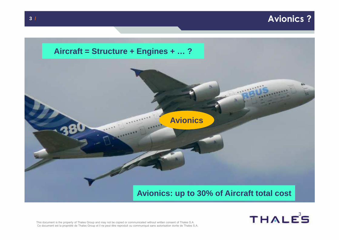
Avionics: up to 30% of Aircraft total costAvionics: up to 30% of Aircraft total cost
Aircraft = Structure + Engines + … ?Aircraft = Structure + Engines + … ?
AvionicsAvionics
4 /4 / Avionics ?
4
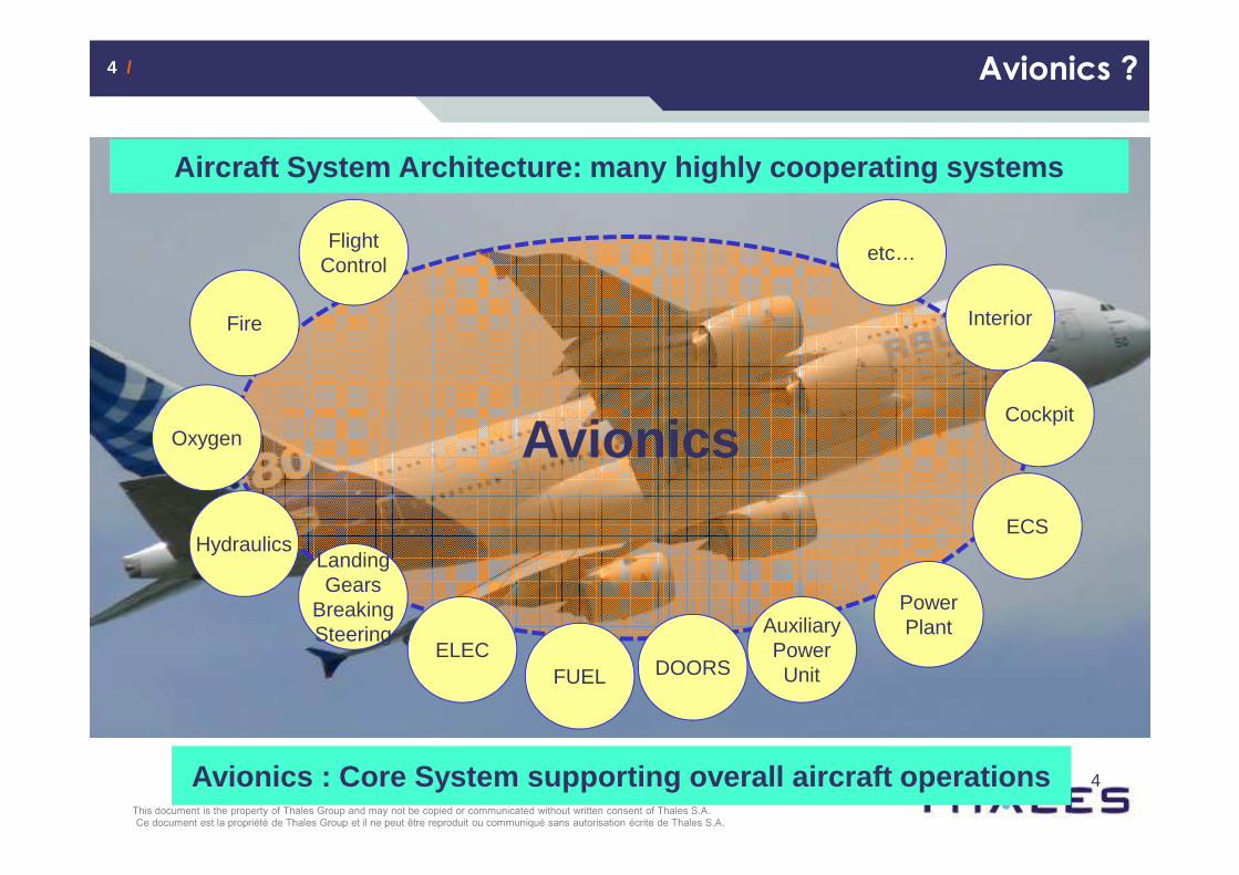
Avionics
HydraulicsLandingGears
BreakingSteering
ELECFUEL DOORS
AuxiliaryPowerUnit
PowerPlant
ECS
OxygenCockpit
Fire Interior
FlightControl
etc…
Aircraft System Architecture: many highly cooperati ng systemsAircraft System Architecture: many highly cooperati ng systems
Avionics : Core System supporting overall aircraft operationsAvionics : Core System supporting overall aircraft operations
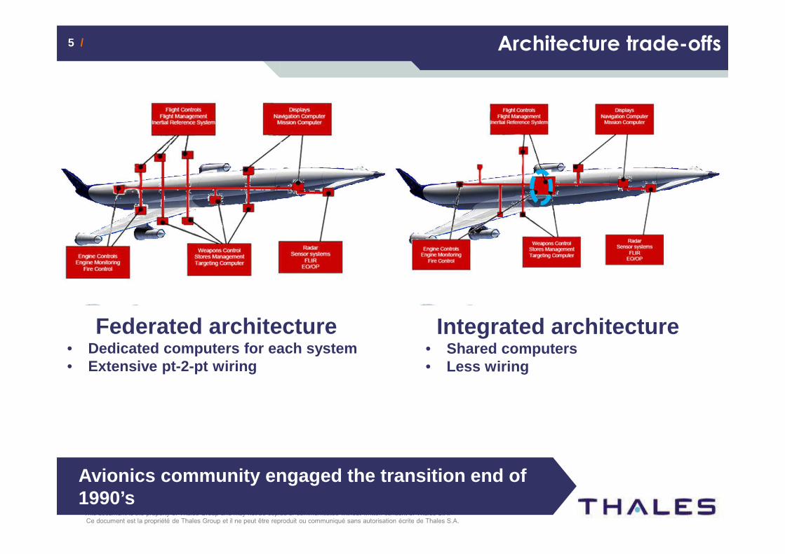
5 /5 / Architecture trade-offs
Federated architecture• Dedicated computers for each system• Extensive pt-2-pt wiring
Integrated architecture• Shared computers• Less wiring
Avionics community engaged the transition end of 1990’s
6 /6 /
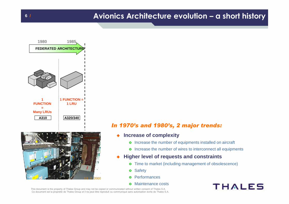
1 FUNCTION
=Many LRUs
1 FUNCTION =1 LRU
1980 1985
FEDERATED ARCHITECTURE
Avionics Architecture evolution – a short history
A320/340A310
In 1970’s and 1980’s, 2 major trends:
� Increase of complexity� Increase the number of equipments installed on aircraft
� Increase the number of wires to interconnect all equipments
� Higher level of requests and constraints� Time to market (including management of obsolescence)
� Safety
� Performances
� Maintenance costs
7 /7 /
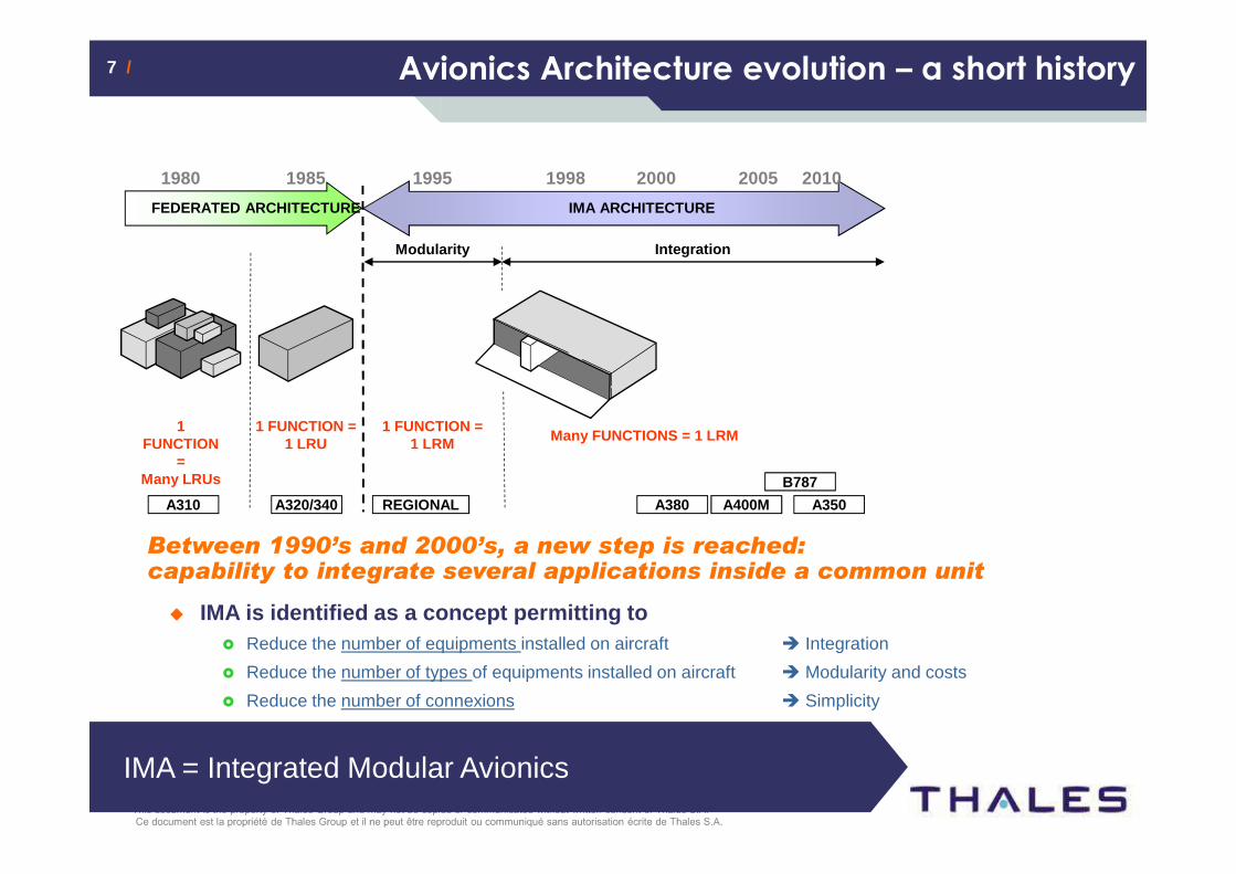
1 FUNCTION
=Many LRUs
1 FUNCTION =1 LRU
1980 1985
FEDERATED ARCHITECTURE
Modularity
1 FUNCTION = 1 LRM Many FUNCTIONS = 1 LRM
1995 1998
IMA ARCHITECTURE
Integration
2000 2005 2010
A320/340A310 REGIONAL A380 A400M A350
Between 1990’s and 2000’s, a new step is reached:capability to integrate several applications inside a common unit
� IMA is identified as a concept permitting to� Reduce the number of equipments installed on aircraft � Integration
� Reduce the number of types of equipments installed on aircraft � Modularity and costs
� Reduce the number of connexions � Simplicity
Avionics Architecture evolution – a short historyAvionics Architecture evolution – a short history
B787
IMA = Integrated Modular Avionics
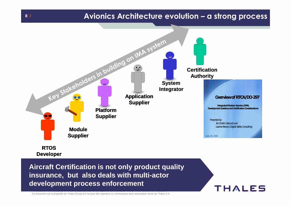
8 /8 / Avionics Architecture evolution – a strong process
Overview of RTCA/DO-297
Presented by:
Jim Chelini (Verocel) and
Leanna Rierson (Digital Safety Consulting)
Integrated Modular Avionics (IMA) Development Guidance and Certification Considerations
June 29, 2006
Aircraft Certification is not only product quality insurance, but also deals with multi-actor development process enforcement
RTOSDeveloper
PlatformSupplier
ApplicationSupplier
Certification Authority
ModuleSupplier
RTOSDeveloper
RTOSDeveloper
SystemIntegratorSystem
Integrator
PlatformSupplierPlatformSupplier
ApplicationSupplier
ApplicationSupplier
Certification Authority
ModuleSupplierModuleSupplier
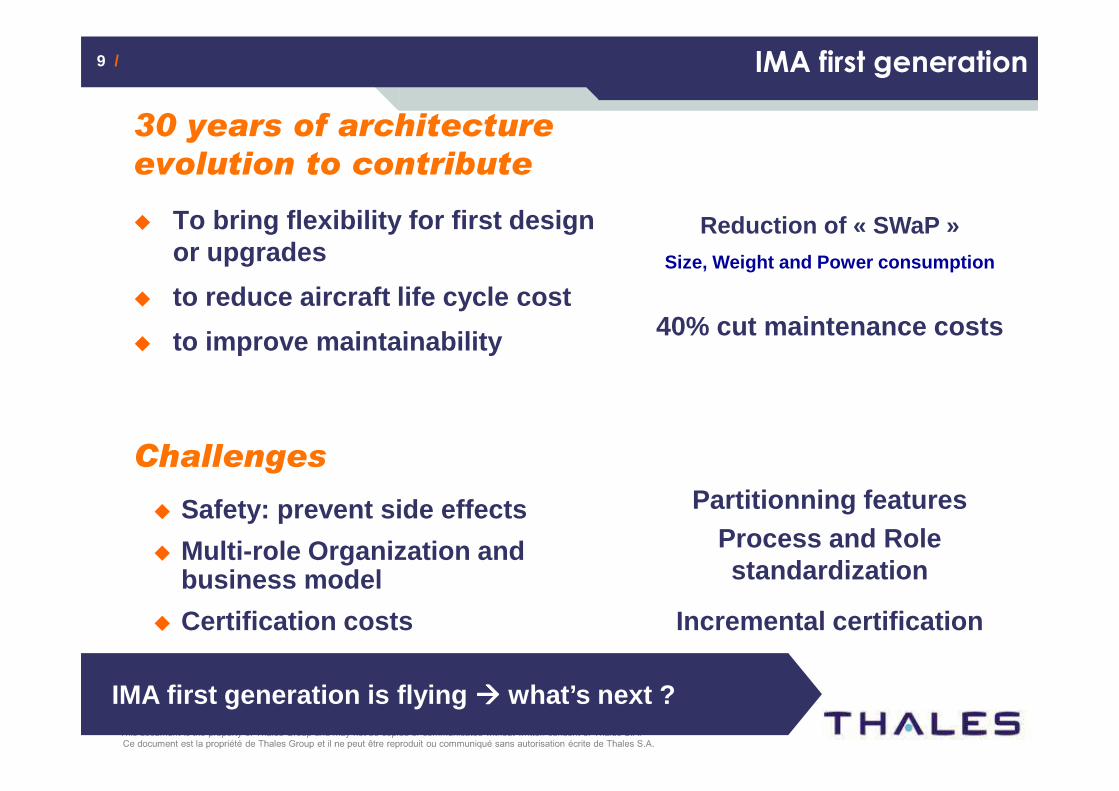
9 /9 / IMA first generation
30 years of architecture
evolution to contribute
� To bring flexibility for first design or upgrades
� to reduce aircraft life cycle cost
� to improve maintainability
Challenges
� Safety: prevent side effects
� Multi-role Organization and business model
� Certification costs
Reduction of « SWaP »Reduction of « SWaP »Size, Weight and Power consumption
40% cut maintenance costs40% cut maintenance costs
Partitionning featuresPartitionning features
Incremental certificationIncremental certification
Process and Rolestandardization
Process and Rolestandardization
IMA first generation is flying ���� what’s next ?
www.thalesgroup.com
IO 2
012
Con
fere
nce
/ 20
12/0
9/25
This document is the property of Thales Group and may not be copied or communicated without written consent of Thales S.A.
An introduction to Avionics
Scarlett presentation
Conclusion
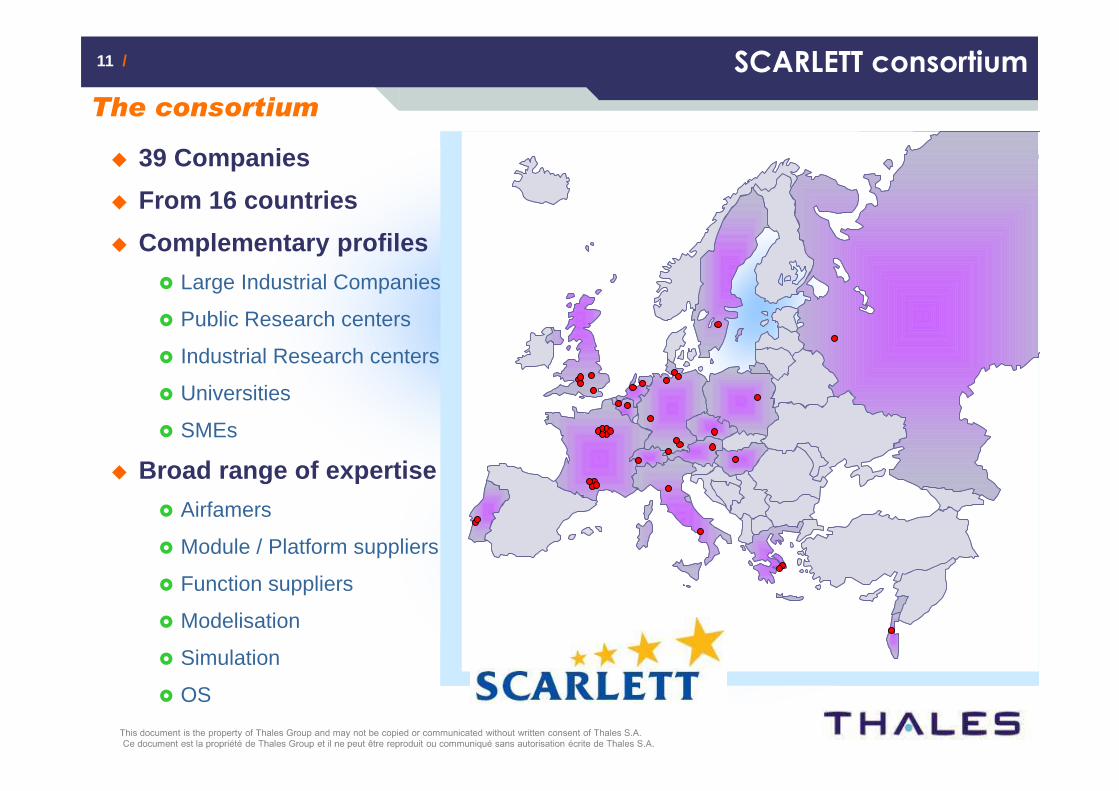
11 /11 / SCARLETT consortium
The consortium
� 39 Companies
� From 16 countries
� Complementary profiles
� Large Industrial Companies
� Public Research centers
� Industrial Research centers
� Universities
� SMEs
� Broad range of expertise
� Airfamers
� Module / Platform suppliers
� Function suppliers
� Modelisation
� Simulation
� OS
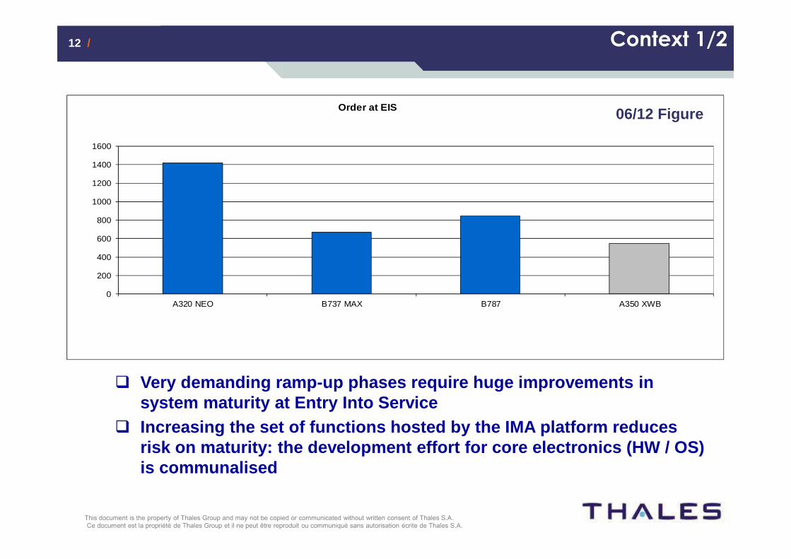
12 /12 /
Aircrafts Orders at Entry In Service
0
200
400
600
800
1000
1200
1400
1600
A320 NEO B737 MAX B787 A350 XWB
Order at EIS 06/12 Figure
� Very demanding ramp-up phases require huge improvem ents in system maturity at Entry Into Service
� Increasing the set of functions hosted by the IMA p latform reduces risk on maturity: the development effort for core e lectronics (HW / OS) is communalised
Context 1/2
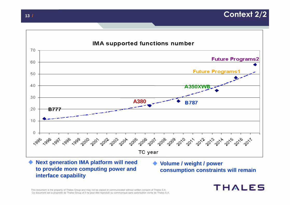
13 /13 /
� Next generation IMA platform will need to provide more computing power and interface capability
� Volume / weight / power consumption constraints will remain
Context 2/2
A380
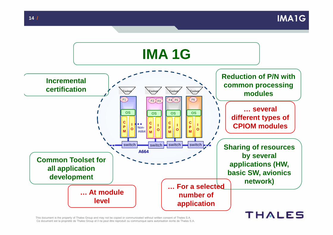
14 /14 / IMA1G
IMA 1GReduction of P/N with common processing
modules
Common Toolset for all application development
Incremental certification
Sharing of resources by several
applications (HW, basic SW, avionics
network)
… several different types of CPIOM modules
… For a selected number of application
… At module level
CPM
IO
OS
Toolset Toolset Toolset
A664
Non-A664
F1 F3F2 F4 F5 F6
Toolset
CPM
IO
OS
CPM
IO
OS
CPM
IO
OS
switch switch switch switch
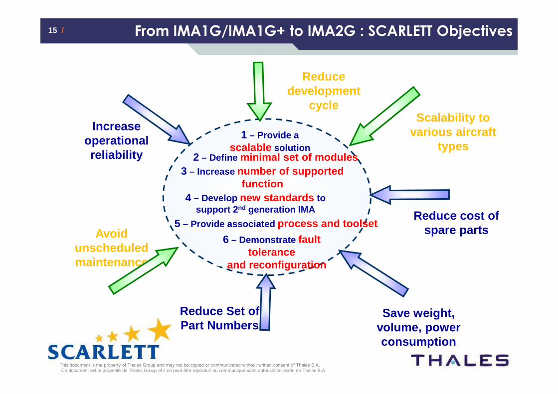
15 /15 / From IMA1G/IMA1G+ to IMA2G : SCARLETT Objectives
Increase operational reliability
Avoid unscheduled maintenance
Reduce Set of Part Numbers
Scalability to various aircraft
types
Reduce development
cycle
Reduce cost of spare parts
1 – Provide a scalable solution
2 – Define minimal set of modules3 – Increase number of supported
function4 – Develop new standards to
support 2 nd generation IMA
5 – Provide associated process and toolset
6 – Demonstrate fault tolerance
-- and reconfiguration
Save weight, volume, power consumption
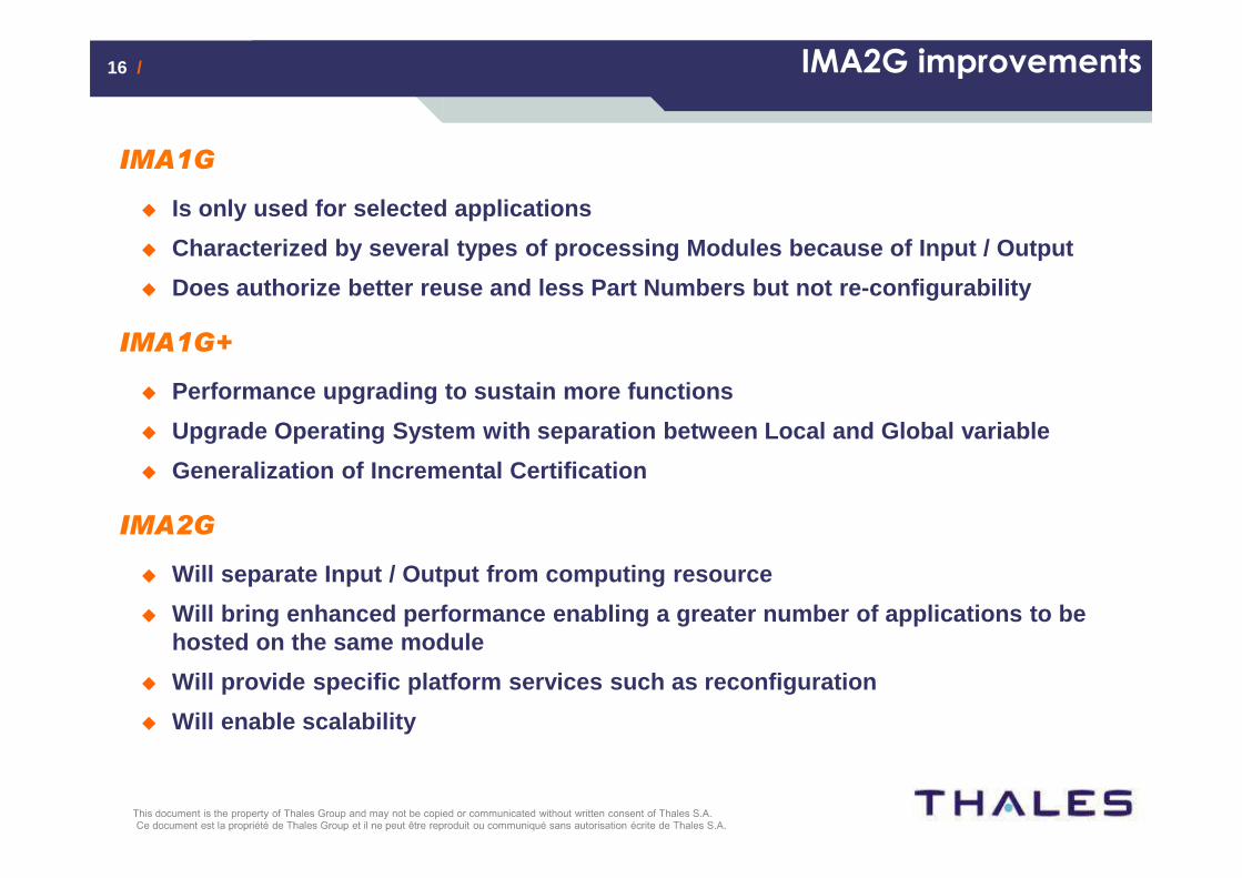
16 /16 / IMA2G improvements
IMA1G
� Is only used for selected applications
� Characterized by several types of processing Module s because of Input / Output
� Does authorize better reuse and less Part Numbers b ut not re-configurability
IMA1G+
� Performance upgrading to sustain more functions
� Upgrade Operating System with separation between Lo cal and Global variable
� Generalization of Incremental Certification
IMA2G
� Will separate Input / Output from computing resourc e
� Will bring enhanced performance enabling a greater number of applications to be hosted on the same module
� Will provide specific platform services such as rec onfiguration
� Will enable scalability
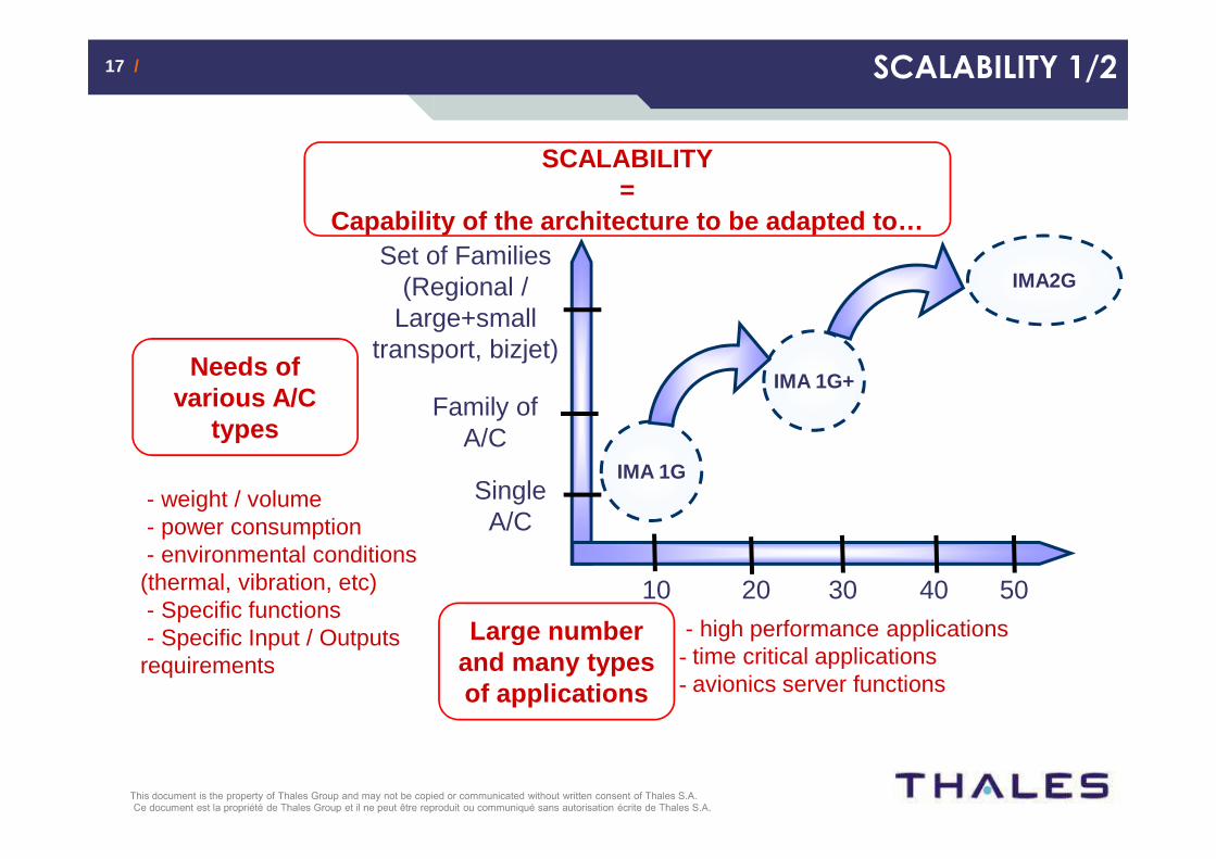
17 /17 / SCALABILITY 1/2
SCALABILITY =
Capability of the architecture to be adapted to…
IMA 1G
IMA2G
Single A/C
Family of A/C
Set of Families (Regional /
Large+small transport, bizjet)
Needs of various A/C
types
- weight / volume- power consumption- environmental conditions
(thermal, vibration, etc)- Specific functions- Specific Input / Outputs
requirements
- high performance applications- time critical applications- avionics server functions
Large number and many types of applications
10 20 30 40 50
IMA 1G+
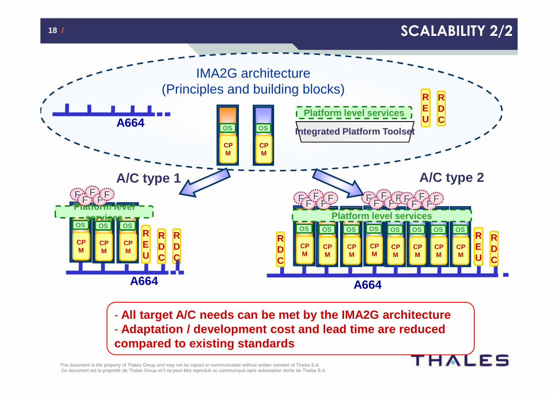
18 /18 / SCALABILITY 2/2
CPM
OS
CPM
OS
IMA2G architecture (Principles and building blocks)
Platform level servicesA664
Integrated Platform Toolset
REU
RDC
A/C type 1
A664
CPM
OS
CPM
OS
CPM
OS
Platform level services
REU
RDC
F FF
FF
RDC
A/C type 2
A664
CPM
OS
CPM
OS
CPM
OS
F FF
FF
RDC
REU
RDC
CPM
OS
CPM
OS
CPM
OS
CPM
OS
CPM
OS
F FF
FF F FF
FF
Platform level services
- All target A/C needs can be met by the IMA2G archit ecture - Adaptation / development cost and lead time are red uced compared to existing standards

19 /19 / Integrated toolset: a challenge for IMA2G adoption
Configuration aspects have increased a lot
DevelopmentDesign Integration Sum of efforts
IMA1G IMA2GWITHOUT IMA
REPARTITION AND AMOUNT OF CONFIGURATION EFFORT
Thus, defining a standard for configuring each IMA2G resources is a must to improve the overall effort required for configuring an aircraft.
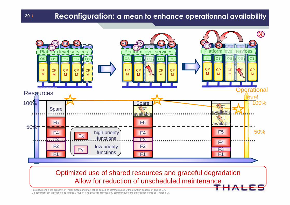
20 /20 / Reconfiguration: a mean to enhance operationnal availability
CPM
OS
CPM
OS
CPM
OS
CPM
OS
CPM
OS
Platform level services
F1 F3 F4 F5F2
CPM
OS
CPM
OS
CPM
OS
CPM
OS
CPM
OS
Platform level services
F1
F
F4F5F3
X
Operational level
F1
F4
F5
F2F3
Spare
Optimized use of shared resources and graceful degradationAllow for reduction of unscheduled maintenance
CPM
OS
CPM
OS
CPM
OS
CPM
OS
CPM
OS
F1 F3 F5 F4
Platform level servicesF2
high priority functions
low priority functionsFy
Fx
50%
100%
Resources
F1
F4
F5
F2F3
SpareNot
available
F1
F4
F5
F3
Notavailable
Notavailable
100%
50%
21 /21 /
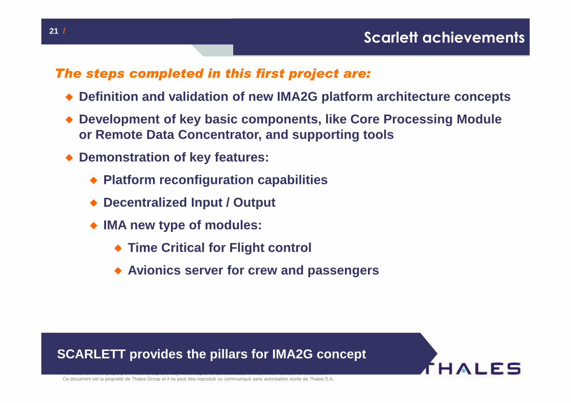
The steps completed in this first project are:
� Definition and validation of new IMA2G platform arc hitecture concepts
� Development of key basic components, like Core Proc essing Module or Remote Data Concentrator, and supporting tools
� Demonstration of key features:
� Platform reconfiguration capabilities
� Decentralized Input / Output
� IMA new type of modules:
� Time Critical for Flight control
� Avionics server for crew and passengers
Scarlett achievements
SCARLETT provides the pillars for IMA2G concept
www.thalesgroup.com
IO 2
012
Con
fere
nce
/ 20
12/0
9/25
This document is the property of Thales Group and may not be copied or communicated without written consent of Thales S.A.
An introduction to Avionics
Scarlett presentation
Conclusion
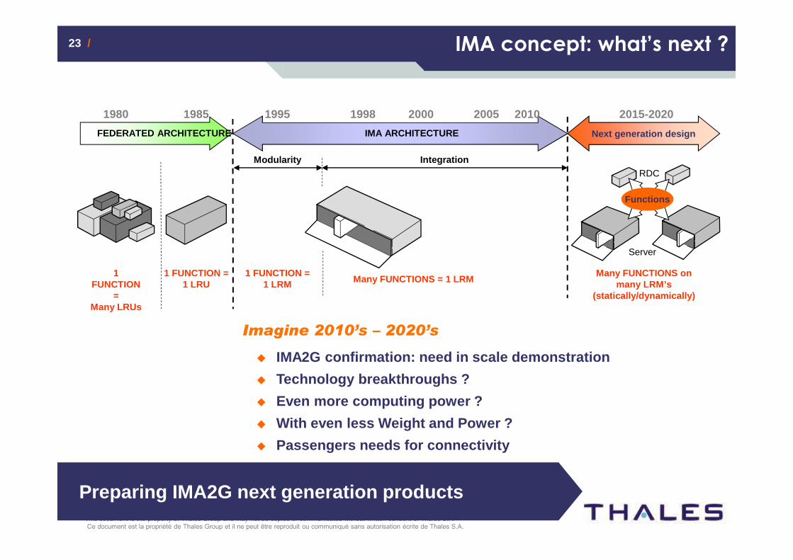
23 /23 /
1 FUNCTION
=Many LRUs
1 FUNCTION =1 LRU
1980 1985
FEDERATED ARCHITECTURE
Modularity
1 FUNCTION = 1 LRM Many FUNCTIONS = 1 LRM
1995 1998
IMA ARCHITECTURE
Integration
2000 2005 2010
Many FUNCTIONS on many LRM’s
(statically/dynamically)
Functions
RDC
Server
2015-2020
Next generation design
Imagine 2010’s – 2020’s
� IMA2G confirmation: need in scale demonstration
� Technology breakthroughs ?
� Even more computing power ?
� With even less Weight and Power ?
� Passengers needs for connectivity
IMA concept: what’s next ?
Preparing IMA2G next generation products
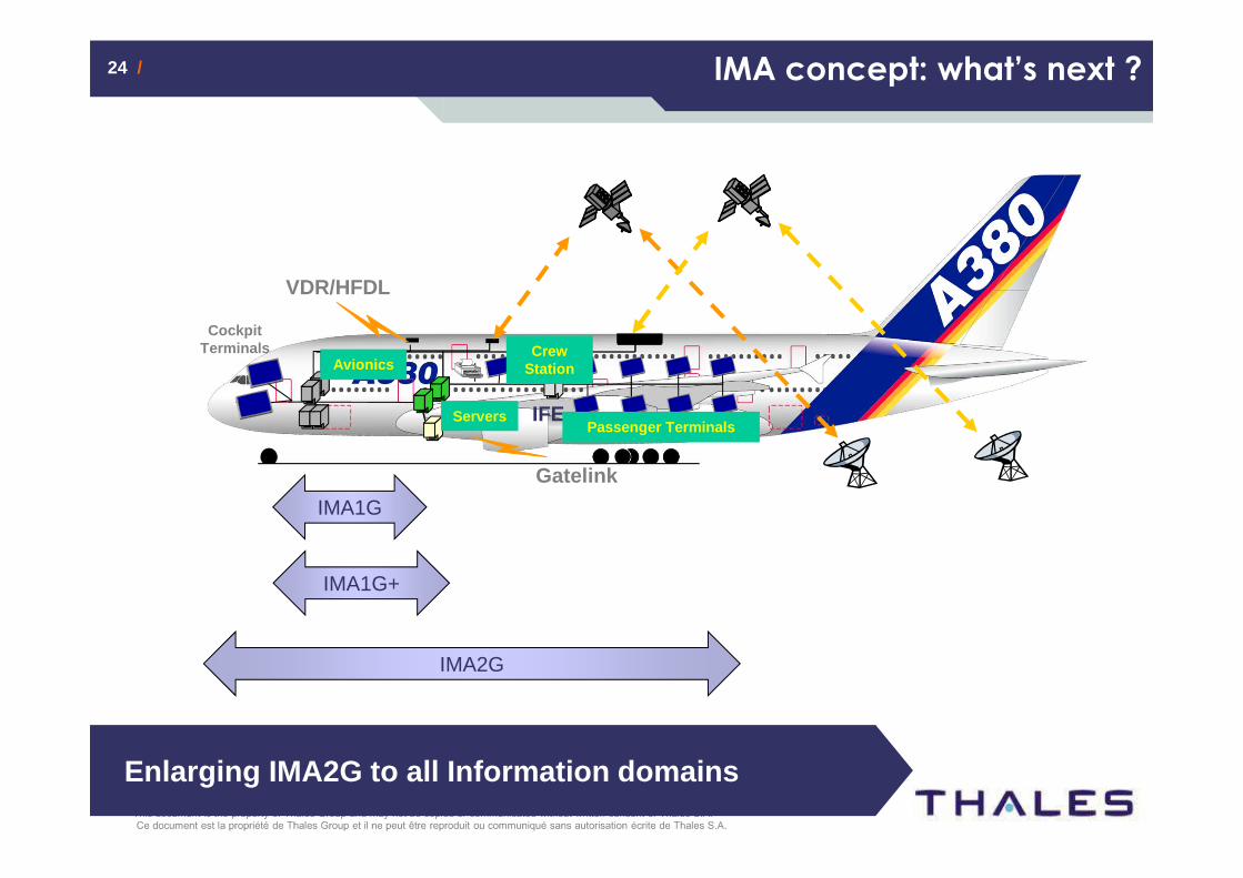
24 /24 / IMA concept: what’s next ?
VDR/HFDL
IFE
Gatelink
TWLUs
Cockpit Terminals
Passenger Terminals
Crew Station
Servers
Avionics
IMA1G
IMA2G
Enlarging IMA2G to all Information domains
IMA1G+
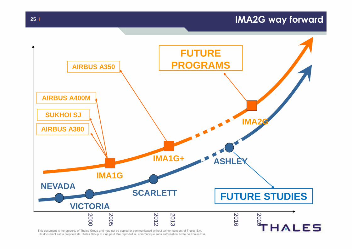
25 /25 / IMA2G way forward
NEVADA
VICTORIA
SCARLETT
SUKHOI SJ
AIRBUS A380
AIRBUS A400M
FUTURE PROGRAMS
ASHLEY
FUTURE STUDIES
IMA1G
IMA2G
IMA1G+
AIRBUS A350
2005
2000
2013
2012
2016
2020
26 /26 /
ContactsMarc Gatti +33(0)[email protected] Hainaut +33(0)[email protected] Bardet +33(0)[email protected]
27 /27 /
Proprietary Notice
This presentation includes THALES Avionics Proprietary Information and Background Intellectual Property Rights.
This presentation, in whole or in part, is confidential and shall not be used or disclosed without THALES Avionics prior written
authorization